Have you look for this feature in other issues and in the wiki?
Yes
Is your feature request related to a problem? Please describe.
No
Describe the solution you'd like
Connect rotary encoder to ESP8266 and send + and - ticks over MQTT
Describe alternatives you've considered
Connect rotary encoder to arduino pro mini and let the arduino pro mini provide turning events + or - via I2C bus to ESP8266
Additional context
The ESP8266 modules have limited pins and it would be easy to make an arduino pro mini act as a I2C slave to provide impulses when the rotary encoder is turned.
(Please, remember to close the issue when the problem has been addressed)
 andrethomas
All 35 comments
Have you tried using rules to read the grey code off the encoder?
 sammy2360
on 7 Jul 2018
sammy2360
on 7 Jul 2018
@sammy2360 Nope, never really used rules before... do you have a rotary encoder to test?
andrethomas
on 7 Jul 2018
yes i have a rotary encoder. it may be possible. ive only just started experimenting with rules. ill give it a try.
sammy2360
on 7 Jul 2018
on closer inspection i dont think rules will help. the encoder switches too fast to be recognised. alot of steps in the grey code get lost. libraries that read rotary encoders use the interupt lines to detect the switching then compare the results of both pins against the last known results.
what is your intended application?
sammy2360
on 7 Jul 2018
Increase and decrease of values/variables on node-red for various applications, dimmers, temperature control, thermal control etc etc - Basically everything one can do from the phone/tablet but an option for human interface that doesn't require you to search for your phone in the dark to turn the light in the baby room up.
andrethomas
on 7 Jul 2018
This issue has been automatically marked as stale because it has not had recent activity. It will be closed if no further activity occurs. Thank you for your contributions.
![stale[bot] picture](https://avatars3.githubusercontent.com/in/1724?v=4&s=40) stale[bot]
on 21 Aug 2018
stale[bot]
on 21 Aug 2018
I would also like to see basic encoder support!!
 nightcat91
on 23 Aug 2018
nightcat91
on 23 Aug 2018
Rotary encoder has proven a bit tricky from my experimentation - Most viable option would likely be to make an 3V3 attiny do the rotary decoding and send state via I2C... so its shelved for now for me, but not forgotten, will get to that method at some point.
andrethomas
on 23 Aug 2018
@andrethomas can you maybe help me get things started?
What version of attiny did you use and do you have a good source for the code it runs?
nightcat91
on 23 Aug 2018
Well, which arduino compatible boards do you have? Any of them would probably work...
andrethomas
on 23 Aug 2018
I have an Arduino Nano on my bench, can I use that?
nightcat91
on 23 Aug 2018
Sure, get rotary encoder to store a value in a uint8_t (say between 0 and 100) and make the encoder increase and decrease this value by turning it - use serial monitor to get it working.
There are many examples for rotary encoders such as these https://playground.arduino.cc/Main/RotaryEncoders
Once you have that working, implement I2C slave code similar to this
#include <Wire.h>

#define  SLAVE_ADDRESS           0x29  //slave address,any number from 0x01 to 0x7F

void setup()
{
   Wire.begin(SLAVE_ADDRESS);
   Wire.onRequest(requestEvent);
   Wire.onReceive(receiveEvent);
}

void loop(){
}

void requestEvent(){
}

void receiveEvent(int bytesReceived){
}
The code is from here http://dsscircuits.com/articles/arduino-i2c-slave-guide
Basically you want your rotary encoder value stored in a uint8_t and be able to have the arduino running as a I2C slave on a specific I2C address (remember its 7bit so anything from 0x01 to 7F)
Then add the code to respond to a specified register to send the value from the arduino board via I2C to the Tasmota firmware (or another I2C master if you have one to test with)
Once you have that you can tweak something simple like the lm75ad driver of Tasmota to make a new one to read your arduino register via I2C
I may have more time to go into more detail over the weekend but if you know what you're doing the above should be enough to get you started.
You can also look at my existing code which is designed to generate JSON values over I2C here but its incomplete and not directly relevant to a rotary encoder (at least not yet) https://github.com/andrethomas/I2CArduSense
andrethomas
on 23 Aug 2018
If you can get the rotary encoder code working and share here then I may add the I2C layer for you if I get time, if its too overwhelming for you - have no idea what your coding competency level is so not sure how much of it you understand :)
Or you could just wait until I get around to it...
andrethomas
on 23 Aug 2018
Thanks a lot, I will have a look at that and let you know when I need more help!
nightcat91
on 25 Aug 2018
Probably not my best work, but is some initial code to toy with
https://github.com/andrethomas/I2cRotaryEncoder
Upload the sketch in I2cRotaryEncoder to your arduino compatible board.
Connect center pin of the rotary encoder to GND and the outer pins to digital pin 2 and 3 on your arduino board respectively.
Then, copy the xsns_91_I2cRotary.ino file to your Sonoff-Tasmota source code folder and add
define USE_I2C_ROTARY
to your user_config.h (or equivalent if you use it another way)
Compile and upload to your test ESP8266 board
Enable seriallog 3
When Tasmota firmware starts you should see the following on the see the following
00:00:01 I2C: I2cRotaryEncoder found at 0x77
The following should appear every 5 seconds
9:30:01 MQT: stat/sonoff/RESULT = {"Time":"2018-08-26T19:30:01","I2cRotary_Value":32}}
The interval can be changed in xsns_91_I2cRotary.ino by changing the value of
define I2C_ROTARY_READ_INTERVAL 5
andrethomas
on 26 Aug 2018
Can you help me to add this to tasmota
 marrobHD
on 5 Nov 2018
marrobHD
on 5 Nov 2018
Is this code working? Its a bit of a faf to have an attiny reading the encoder and reporting its findings to the esp8266. But if it is working then put in a pull request to have it assessed and possibly added.
I did start to try and get tasmota to read the encoder directly but i think the required interupts will slow the system down or cause errors. Can you use a potentiometer instead? You can get them without stoppers and clicky ones that feel just like encoders.
sammy2360
on 5 Nov 2018
Is this code working?
Yes, but incomplete and therefore not yet incorporated into Tasmota as a "thing"
Its a bit of a faf to have an attiny
Dont think the tiny will run fast enough with the code in its current form
Can you use a potentiometer instead?
Yes, you can use the A0 input on the ESP8266 in Tasmota.
@Jason2866 and I actually discussed this driver over the weekend sometime and we decided that we may include PWM output support as well as AC zero cross detection so that it can be used for AC dimming applications also.
andrethomas
on 5 Nov 2018
@andrethomas
I was not able to try and mess around with your code from above.... just had too many other things around the house.
But I love the fact that you are thinking about adding this to tasmota software.
I wanted to use an encoder to replace an analog potentiometer that is dimming a light. I went towards encoder because I wanted to be able to dimm the light up or down no matter if it has been changed through other means (using HomeAssistant on a phone?).
So you could go ahead and turn the light on via the push down action from the encoder and then use the encoder to dimm it to 50%.
Then if you go ahead and use software in a smartphone to change the dimming to 20%.
Now with a potentiometer (analog) if you touch it to turn it to dimm the light from 20% to 40% it would first jump back to 50% because thats the value the potentiometer was left at (i hope you understand what I am trying to say).
With an encoder you would just use a few ticks to change the dim level from 20% up to 40%.
@Jason2866 and I actually discussed this driver over the weekend sometime and we decided that we may include PWM output support as well as AC zero cross detection so that it can be used for AC dimming applications also.
Even though I dont know what AC zero cross detection is, overall this sounds very good
nightcat91
on 5 Nov 2018
These boards are about £5. All the hard work is done. Would make sense to write this into tasmota.
https://github.com/Fattoresaimon/I2CEncoderV2/blob/master/README.md
sammy2360
on 7 Nov 2018
@sammy2360
that looks very nice what you found there.
I really hope this can be implemented into tasmota. Then I will be ordering like 10-20 of those pcb boards
nightcat91
on 7 Nov 2018
Should be fairly simple to implement a driver for that.
Still going to proceed with initial work to add pwm and zero crossing detection as the application I have in mind is a PWM controlled AC dimmer using a SSR that can be controlled either with the rotary encoder or by means of sending mqtt messages to it.
andrethomas
on 7 Nov 2018
Yes as was stated before one of the existing i2c intergrations in tasmota could be copied and edited to work with this encoder board. As it is a product that is available, my opinion is that it is the better way to include rotary encoder support for the home automation enthusiasts that dont have the programming or electronics skills to make a pcb with microcontroller to achieve rotary encoder intergration.
sammy2360
on 8 Nov 2018
@sammy2360 Go for it, no reason not to ;)
andrethomas
on 8 Nov 2018
I found two more rescources, maybe they are useful to anyone here:
https://github.com/LennartHennigs/ESPRotary/blob/master/README.md
https://arduino.stackexchange.com/questions/30012/how-to-use-a-rotary-encoder-on-nodemcu-with-arduino-code
nightcat91
on 16 Nov 2018
They both use interupt routines to read the encoder. This will more than likely cause issues in tasmota. I have received the rotary encoder pcb through the post. I will begin experimenting soon. Have been busy with other things recently.
sammy2360
on 16 Nov 2018
Hello. Just an update. Have had success with the i2c encoder pcb. Just tidings the code up and adding some settings for max and min limits and also steps. Havent started coding for the push button yet but is on the list. Also want to add a setting for directly controlling brightness. At the moment using rules for this but it is quite laggy.
sammy2360
on 27 Nov 2018
ok very basic working example on my fork https://github.com/sammy2360/Sonoff-Tasmota/tree/encoder-development. will do dimming and can be used with rules. please have a go and let me know what you think. i dont want to pull it to the main development just yet as there is more work to be done.
this is the module used about £6
https://coolcomponents.co.uk/products/i2c-encoder-v2?variant=13065685762109&gclid=Cj0KCQiAoo7gBRDuARIsANeJKUaWlV5LqjMq00QT-TQGSQQxVkI_agcQ23ai52Q8S6gd8BIlUEVN-okaAvyVEALw_wcB
and for you americans about $6.50
https://www.tindie.com/products/Saimon/i2cencoder-v2-connect-multiple-encoder-on-i2c-bus/
backlog module 18; gpio4 6; gpio5 5; gpio15 7; teleperiod 20; encodermaxlimit 127; EncoderMinLimit 0; encodersteps 1
should get things going on wemos d1. connect SDA to GPIO 4 and SCL to GPIO 5. 3.3v and GND. no need to connect INT. will also need the standard 4k7 resistors from SDA and SCL to 3.3v. on the i2c bus. solder A0 to give the module addrerss 0x01.
sammy2360
on 2 Dec 2018
Hi Sammy2360, how are things going with the rotary encoder i2c boards? I am wanting to integrate these with some of these http://www.moeshouse.com/p_view.asp?pid=4
These dimmers work great on tasmota and AU 240v but I am wanting to get a legacy dimmer control option going instead of the touch panel (will mount dimmer module behind wall) so the home automation is able to be operated without instructing guests how it works and to preserve the look of the switch plates through the house. I already have some of the V2 Encoder boards.
Thanks
Brett
 brettlg
on 13 Apr 2019
brettlg
on 13 Apr 2019
Hi Brett,
Unfortunately i have had no time to work on this any further. And by now its likely to be out of date with the current releases of tasmota. What i had done seemed to work just fine. If you are interested please have a go with my version of tasmota and see what you think. Rules are the best way to get things up and running as the encoder just shows up as a sensor. If you have any coding knowledge or anyone else reading this would like to take up the project and continue its development, feel free as like ive said I currently have no time free to work on it. Any more questions do feel free to ask ill try help out as much as i can. Thanks Sam
sammy2360
on 13 Apr 2019
Hi Sam,
Thanks for your quick reply.
I tried compiling your source from your fork of Tasmota but am getting errors see image.
I can scan the i2c bus and see the device with stock tasmota.
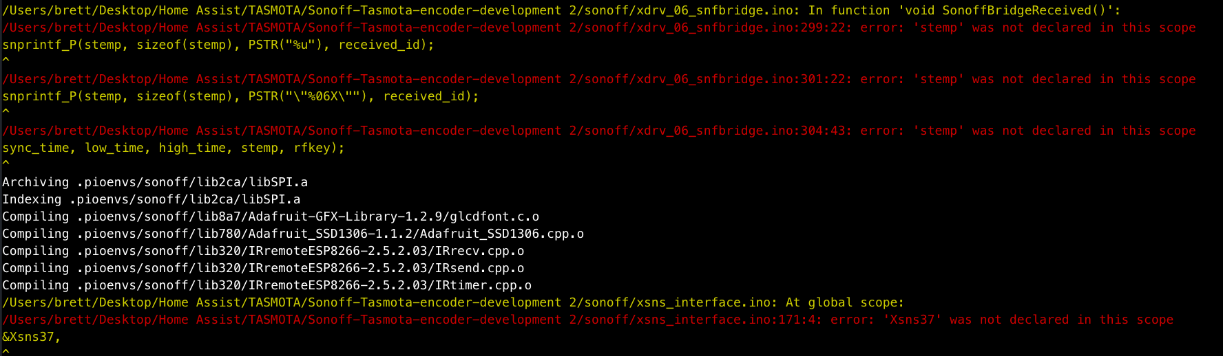
Are there any options I need to disable or enable before compiling to make this sensor available? Also you mentioned rules. Do you have any examples you could share? I am very much a NOOB at this kind of programming and the layout of the Tasmota source.
Thanks again
Brett
brettlg
on 14 Apr 2019
hi Brett,
have adjusted a small typo and is compiling fine now. make sure on github that the encoder development branch is selected before downloading. sorry forgot to mention that before.
some settings for use in the console
EncoderMaxLimit
EncoderMinLimit
EncoderSteps
as for rules you can use the trigger ENCODER#E1
the rules are very powerful. do look at the wiki for rules examples. they are very strait forward to learn.
looking back over the code looks like encode 1 works with the dimming of the first channel. encoder 2 works dimming of 2nd channel and so on. although rules will work it will still operate the dimmer also. this is as far as i got with the code until real life got in the way.
thanks
sam
sammy2360
on 14 Apr 2019
Hi Sam,
Thanks for that. It is now compiling and uploading without error.
Are the only changes in firmware the addition of the files i2cEncoderLibV2.cpp & i2cEncoderLibV2.h to the lib folder, the addition of xsns_37_i2cencoder.ino to the sonnof folder and the insertion of the lines #define USE_I2CENCODER & #define NUMBER_OF_ENCODERS 1 to my_user_config.h? I would like to have a stab at getting it running on latest tasmota build. What model Sonnof did you have the firmware working on? I can compile and upload but I cannot get wifi configured. I guessing that portion of code had to be left out due to space restrictions. If i enter wifi info in source files before compiling I can see it on the network. I am using a sonoff th-10 and have found that I can set the module as th-10 ok but when I go to assign gpis 1 & 3 to i2c the unit drops all settings. I realise your busy but I appreciate (envy) your knowledge implementing the encoder module so far. This is a steep learning curve fo me.
Thanks again
Brett
brettlg
on 15 Apr 2019
Hi brett. Glad its compling now. I had it running on a nodemcu for developing. None of the wifi files where changed so shouldnt be affected by the encoder. Try to avoid using the tx pin on the sonoff as if it is pulled low on startup it can put the esp into a different boot mode. There are a few more lines added to some more of the files. Best thing to do is use the find tool in the ide. Im afraid its all far from my memory to remember every change i made. If you wanted to develop it yourself best thing is to start over using my code as a guide. But work your way through the tasmota firmware yourself. Its not too complicated when you start getting into it. Everyone started somewhere with coding and programming. Give it a go. Ill help if i can.
sammy2360
on 15 Apr 2019
Probably not my best work, but is some initial code to toy with
https://github.com/andrethomas/I2cRotaryEncoder
Upload the sketch in I2cRotaryEncoder to your arduino compatible board.
Connect center pin of the rotary encoder to GND and the outer pins to digital pin 2 and 3 on your arduino board respectively.
Then, copy the xsns_91_I2cRotary.ino file to your Sonoff-Tasmota source code folder and add
define USE_I2C_ROTARY
to your user_config.h (or equivalent if you use it another way)
Compile and upload to your test ESP8266 board
Enable seriallog 3
When Tasmota firmware starts you should see the following on the see the following
00:00:01 I2C: I2cRotaryEncoder found at 0x77The following should appear every 5 seconds
9:30:01 MQT: stat/sonoff/RESULT = {"Time":"2018-08-26T19:30:01","I2cRotary_Value":32}}The interval can be changed in xsns_91_I2cRotary.ino by changing the value of
define I2C_ROTARY_READ_INTERVAL 5
I've Added an small improved Code of Yours to your Github "ISSUES" Part. hope it helps someone, too.
 feedbagg
on 10 May 2020
feedbagg
on 10 May 2020
Related issues
 Vujagig
·
3Comments
Vujagig
·
3Comments
 garret
·
3Comments
garret
·
3Comments
 Joeyhza
·
3Comments
Joeyhza
·
3Comments
 ximonline
·
3Comments
ximonline
·
3Comments
 he-so
·
3Comments
he-so
·
3Comments
Most helpful comment
Hello. Just an update. Have had success with the i2c encoder pcb. Just tidings the code up and adding some settings for max and min limits and also steps. Havent started coding for the push button yet but is on the list. Also want to add a setting for directly controlling brightness. At the moment using rules for this but it is quite laggy.