Hi, Just ordered 2 of these and was wondering if there will be any support for them in the near future ?
Sonoff iFan02: Convert Non-smart LED Ceiling Fan to WiFi Smart Ceiling Fan with Light
Model: IM170811003
Remote ON/OFF–Turn on/off the fan and light from anywhere
Control Fan Speed–Change the fan speed level: 1/2/3/Smart
Adjust the light intensity–Dimmable lights support: white/warm white/warm
Thanks
 sleezy100
All 373 comments
I just ordered 9 on the same assumption. There's probably just a pin to PWM for the LED, not sure about the speed. And getting that remote to still work will be fun.
 abzman
on 27 May 2018
abzman
on 27 May 2018
Support might me added but do not expect it within 8 weeks.
 arendst
on 28 May 2018
arendst
on 28 May 2018
I can ship you one if it'll help but I understand if you have other time demands. I can probably hack in some support for the basics, not sure about the remote or the fan speeds though.
abzman
on 29 May 2018
I can wait I just ordered 1
 MYLE-01
on 29 May 2018
MYLE-01
on 29 May 2018
Me too. Got one on the way.
 Snipercaine
on 10 Jun 2018
Snipercaine
on 10 Jun 2018
Really great if support is added! Got one. Don’t know how it works though to control speed and light color
 ageorgios
on 12 Jun 2018
ageorgios
on 12 Jun 2018
Im going to assume it works exactly the same as everyother fan controller, it just uses a different comms protocol to communicate to it than the switch.
But these look out standing, and i will be upgrading as soon as we have some custom firmware for them!
 palitu
on 15 Jun 2018
palitu
on 15 Jun 2018
to be honest - i wont be waiting for firmware - i'll just use the controller for now
palitu
on 15 Jun 2018
Anxious to see who gets one first and pops it open.
 digiblur
on 15 Jun 2018
digiblur
on 15 Jun 2018
we have a couple en route...
On Fri, Jun 15, 2018 at 11:09 AM digiblur notifications@github.com wrote:
Anxious to see who gets one first and pops it open.
—
You are receiving this because you commented.
Reply to this email directly, view it on GitHub
https://github.com/arendst/Sonoff-Tasmota/issues/2839#issuecomment-397500468,
or mute the thread
https://github.com/notifications/unsubscribe-auth/AGU9IFaxEITGEFKVh1zZwYRljyjFDYFzks5t8yV7gaJpZM4UPDk4
.
palitu
on 15 Jun 2018
I just love that it is a pop in replacement, and has WAF via the remote
control (i already have a remote on my fans) and will integrate into Home
Assistant, so i can turn on and off with motion sensors etc.
And in the mean time, i can just use it as is!
On Fri, Jun 15, 2018 at 11:17 AM Leigh van der Merwe palitu822@gmail.com
wrote:
we have a couple en route...
On Fri, Jun 15, 2018 at 11:09 AM digiblur notifications@github.com
wrote:Anxious to see who gets one first and pops it open.
—
You are receiving this because you commented.
Reply to this email directly, view it on GitHub
https://github.com/arendst/Sonoff-Tasmota/issues/2839#issuecomment-397500468,
or mute the thread
https://github.com/notifications/unsubscribe-auth/AGU9IFaxEITGEFKVh1zZwYRljyjFDYFzks5t8yV7gaJpZM4UPDk4
.
palitu
on 15 Jun 2018
What the fun without tasmota.... Hehe
 tyjtyj
on 15 Jun 2018
tyjtyj
on 15 Jun 2018
oh no - i want Tasmota on it, but i can improve what i have in the mean time :)
palitu
on 15 Jun 2018
I can wait , thanks 👍
 PrathikGopal
on 18 Jun 2018
PrathikGopal
on 18 Jun 2018
I ordered a few of them, but the ebay vendor canceled my order. Now the item appears to have disappeared from ebay entirely?
 WayneManion
on 21 Jun 2018
WayneManion
on 21 Jun 2018
I just got shipping confirmation from iTead.
Snipercaine
on 21 Jun 2018
Can't wait to see internal pics!
digiblur
on 21 Jun 2018
My ifan02 is on the way. When received all I need is a fan (LOL) and good weather...
arendst
on 23 Jun 2018
ordered 2 of them and are being delivered via DHL today ... will post pictures as soon as they get here .... feels like Christmas morning ... lol
 nmatt25
on 25 Jun 2018
nmatt25
on 25 Jun 2018


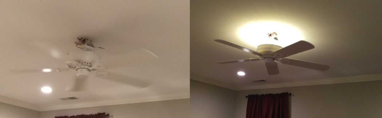
now for the install
nmatt25
on 25 Jun 2018


nmatt25
on 25 Jun 2018
Good News:
OK ... Install went painless as expected. Just swapped out old harbor breeze wireless controller with new sonoff new one. Once powered up I easily paired controller with the eWeLink app on my phone and then proceeded to discover new devices via Alexa app and all went well and I can control everything via the remote, eWelink app, and Alexa via voice.
Bad News:
When I proceeded to test all the functions I started with the easy part which was turning on and off the light which worked but only On or Off no "dimming" but maybe I am doing something wrong but will look into that further. Next went to test the fan .... Let me start with saying that yes I did make sure that I had the pull chain set in the position for the fan to be on HIGH/Full speed. When I turned on the fan via the remote by pressing 3 (high) the fan came on but did not seem like it was the full speed (doubled checked the chain setting) so I figured I would check the 2 (medium) button and the fan slowed but seemed like it was WAY slower then medium and then tried 1 (low) which resulted in the fan barely even spinning. I am not sure if this is something that can be corrected via firmware or not but it is very disappointing and think I am going to wait to install the second one until further testing.
Next Project:
now to see about integration with Home Assistant!
nmatt25
on 25 Jun 2018
Thanks Matt!
Snipercaine
on 25 Jun 2018
I don't recall the light being dimmable on their description. Curious to see someone put a volt/current meter measurements on it. I do see a few jumper pins.
digiblur
on 25 Jun 2018
this is from there site but like I said maybe I'm missing something ... lol
Remote ON/OFF–Turn on/off the fan and light from anywhere
Control Fan Speed–Change the fan speed level: 1/2/3/Smart
Adjust the light intensity–Dimmable lights support: white/warm white/warm
App Support –Free iOS and Android mobile App eWeLink
Sync Status–Real-time device status provided to App
Timing–Set scheduled/countdown to turn on/off at a specified time
Share Control– Control your smart home together with your family
Scene–Turn on/off a gang of devices with one tap
Smart Scene–Triggered on/off the fan or light by environmental conditions from sensor
Compatibility –Works perfectly with Amazon Alexa, Google Assistant, Google Nest
https://www.itead.cc/sonoff-ifan02-wifi-smart-ceiling-fan-with-light.html
nmatt25
on 25 Jun 2018
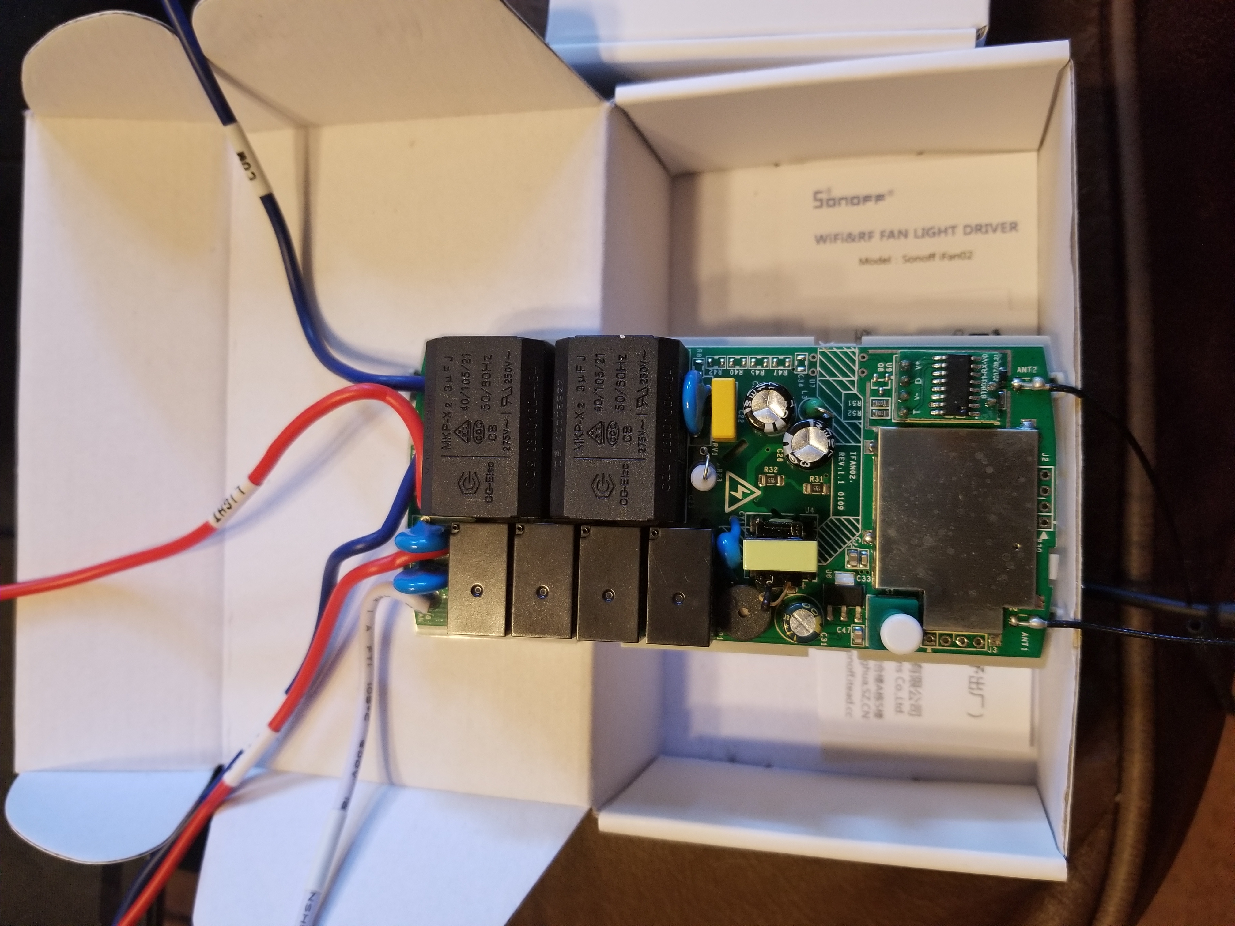
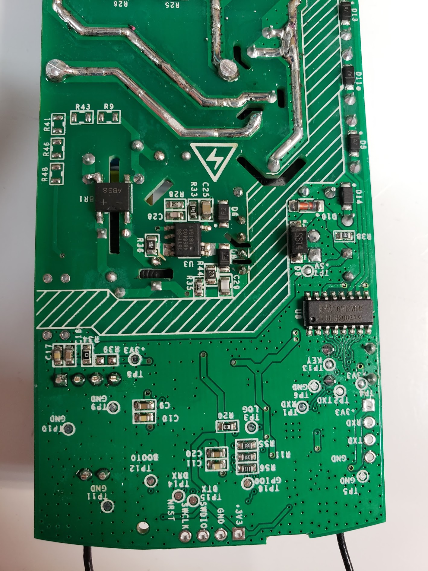
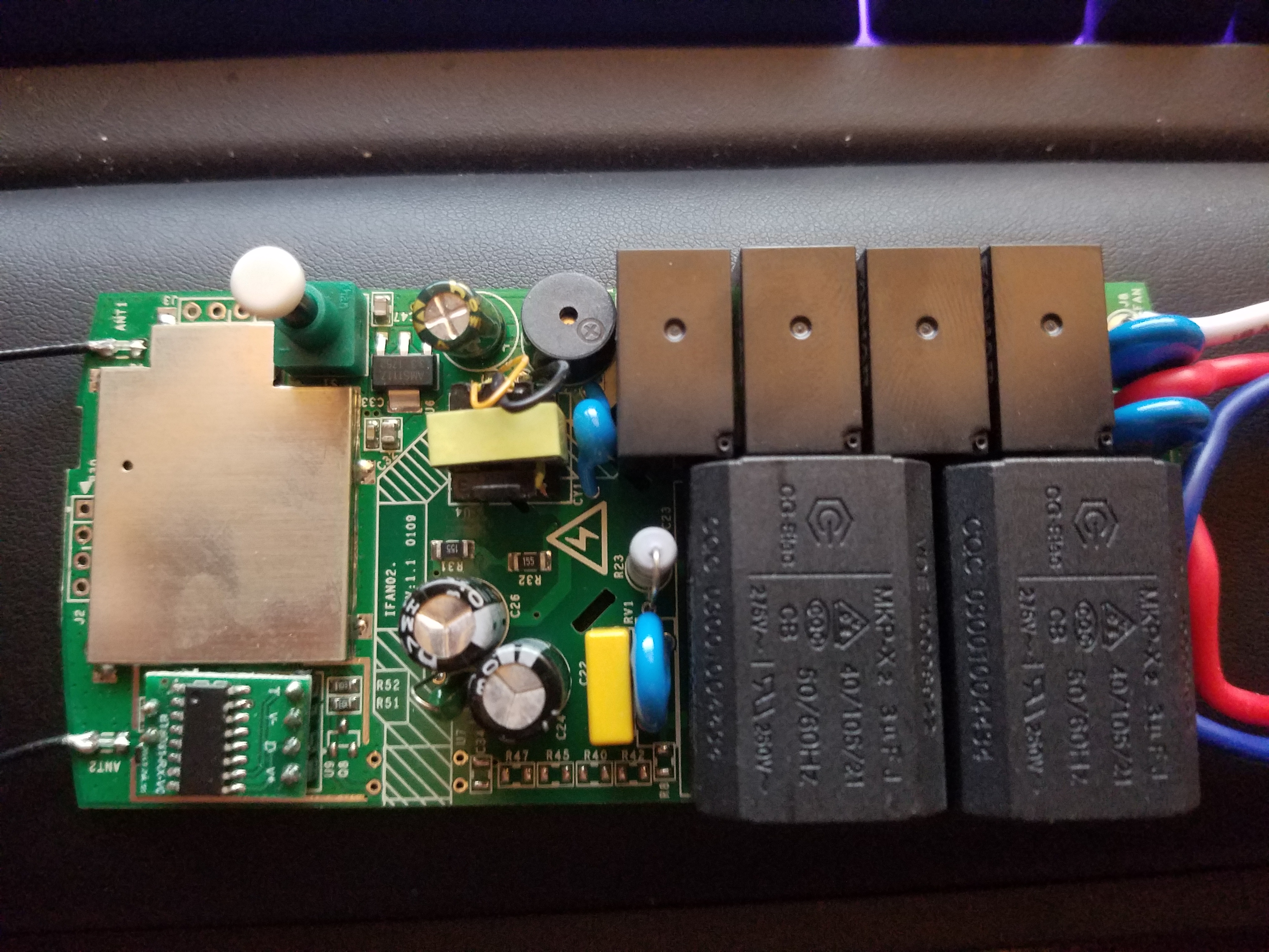
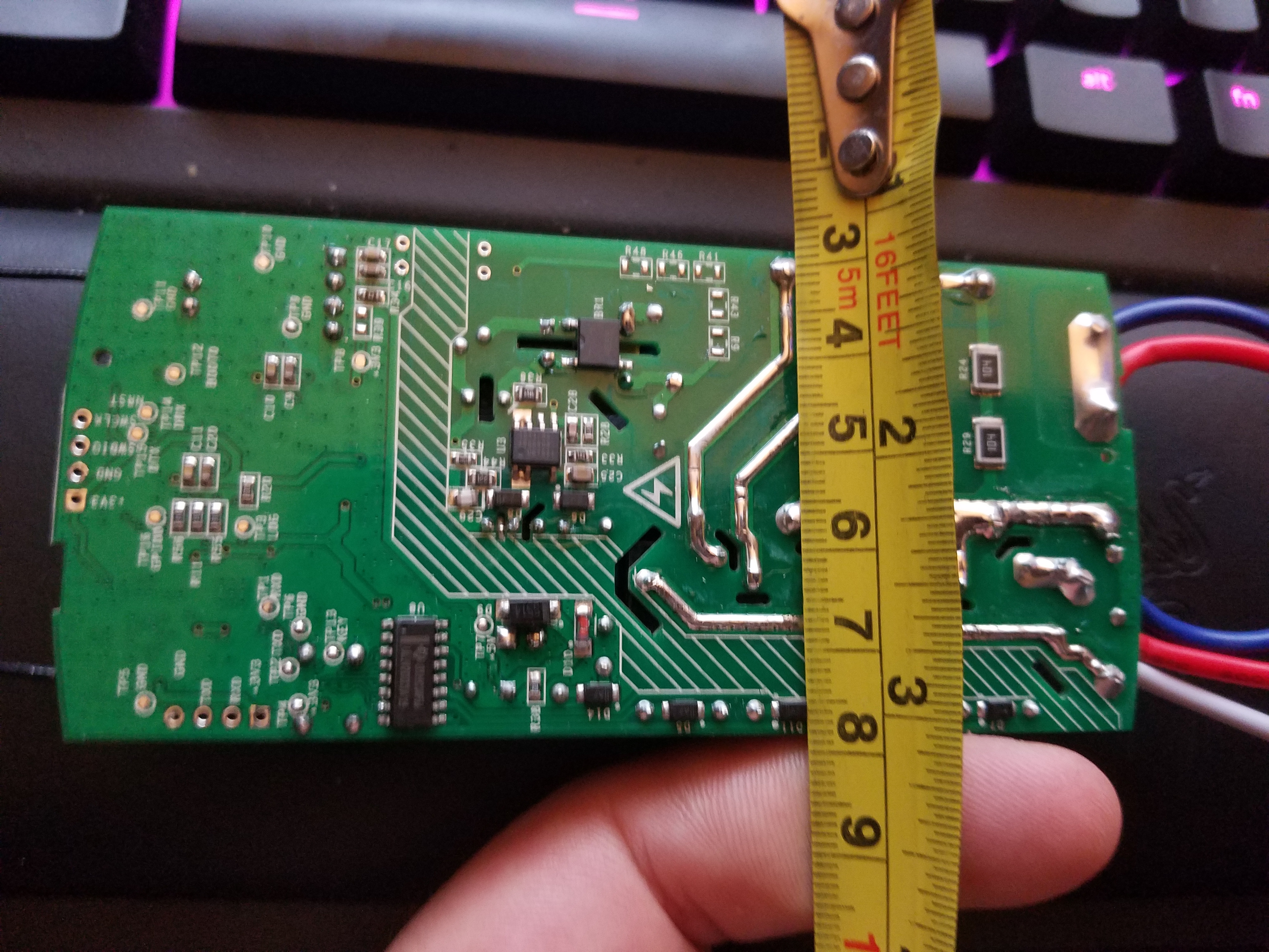
I don't know how they're claiming that there's a bicolor, color-temp adjustable LED output on this thing, it's clearly just one relay for the output on the light. I'll trace more of it later, interested in getting under the can and also sniffing the remote (probably 433mhz)
one of these even: https://www.alibaba.com/product-detail/Hot-selling-FANHAR-W11-1A2STE-5VDC_60553617588.html
abzman
on 26 Jun 2018
I would imagine that there is a triac chopping the wave to dim the light a bit.
Hopefully the fan integration actually works!
palitu
on 26 Jun 2018
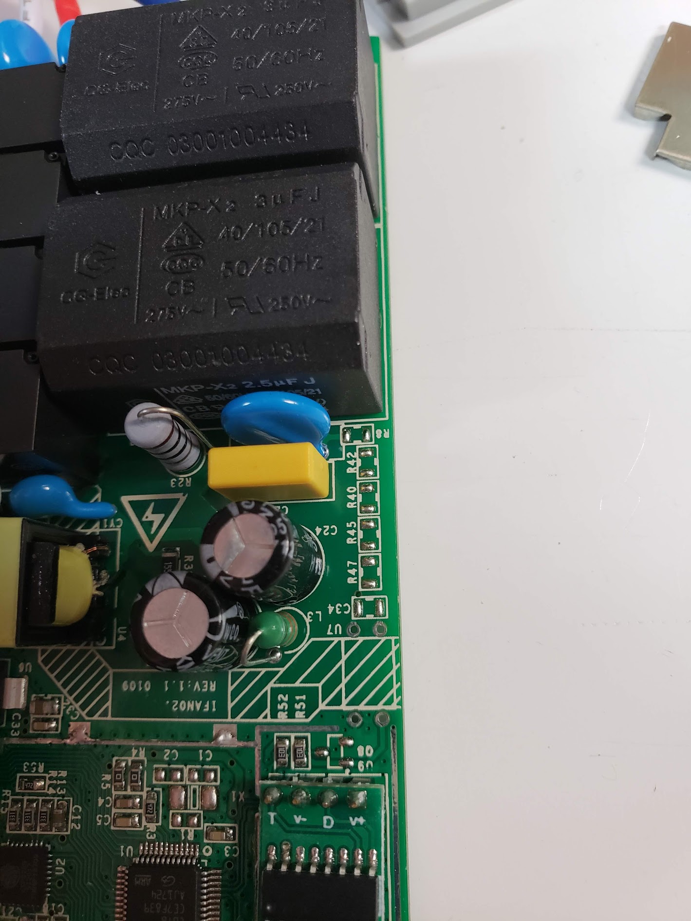
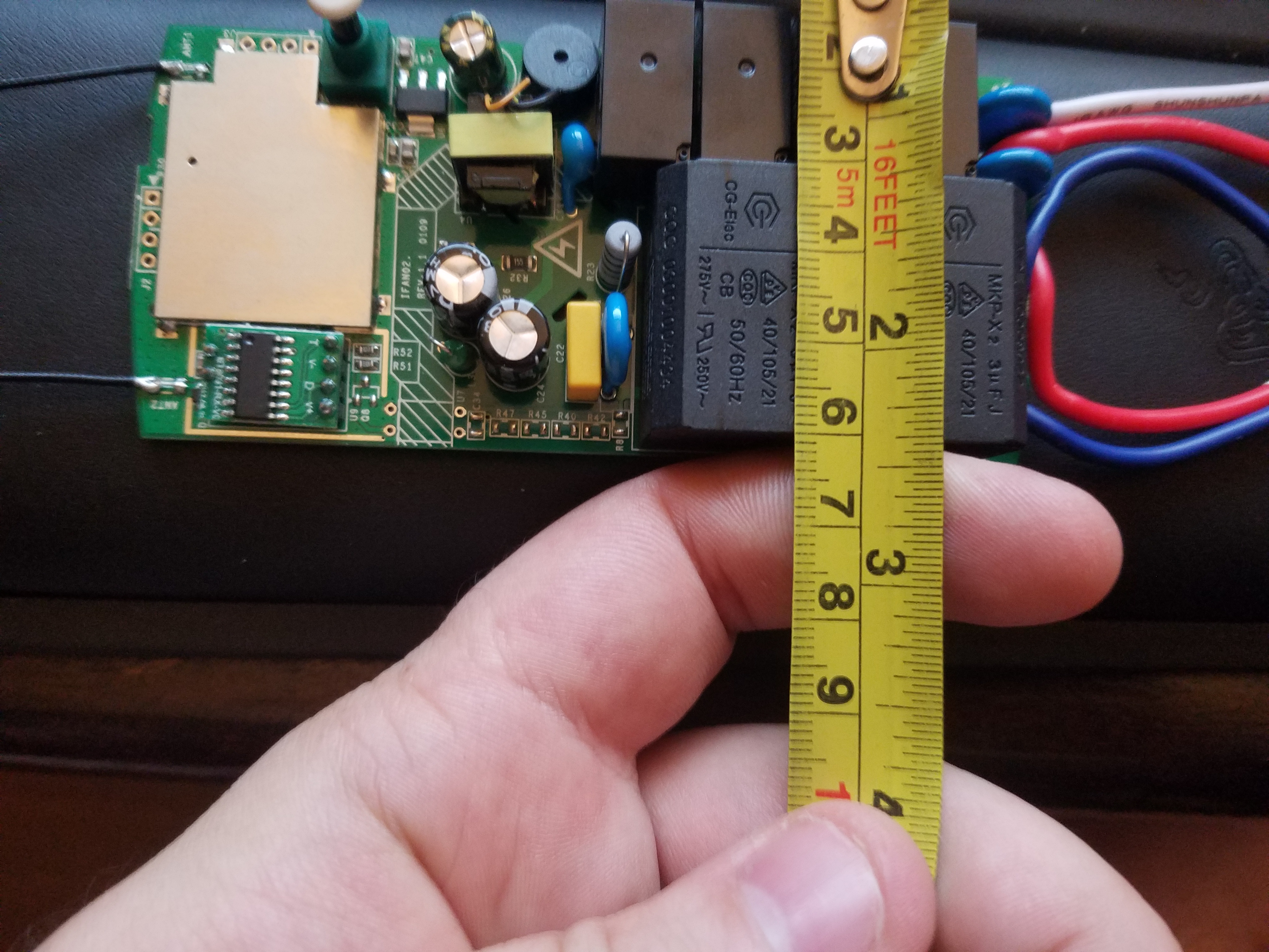
Take a look at these pictures and correlate to the picture of the top showing 4 relays in a row, it's just the last relay that connects the light output to the live input.
abzman
on 26 Jun 2018
There is an arm just for the remote? god, why?
abzman
on 27 Jun 2018
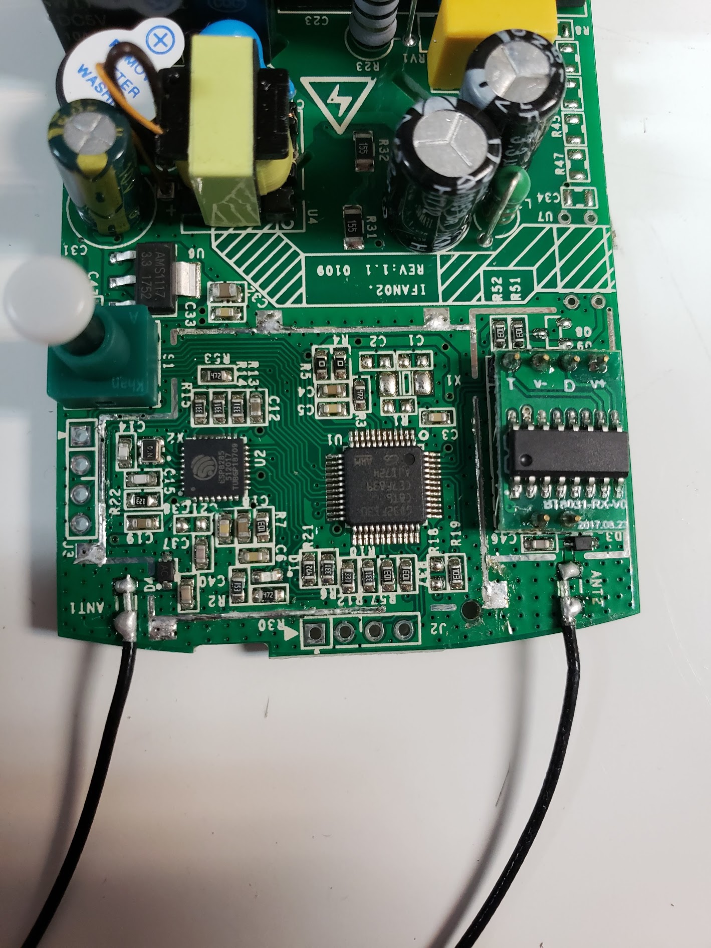
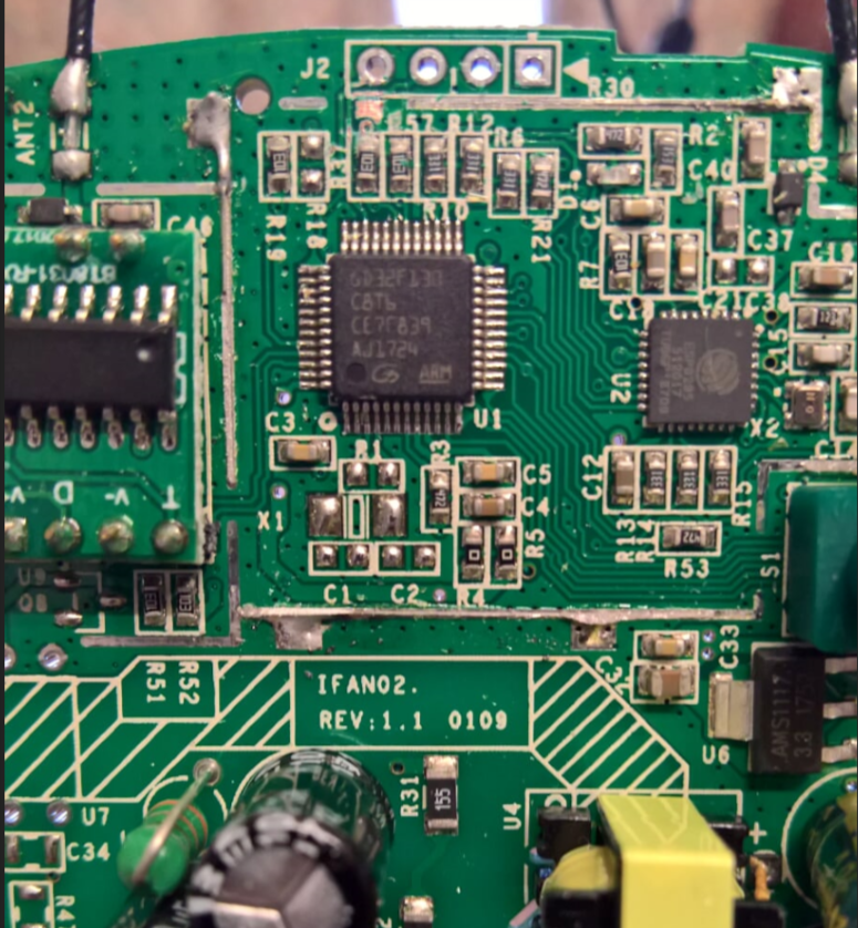
I spy an ESP8285 ;) :)
digiblur
on 28 Jun 2018
I was wrong, it looks like the ARM controls the relays through the driver. This may be harder than I thought...
abzman
on 28 Jun 2018
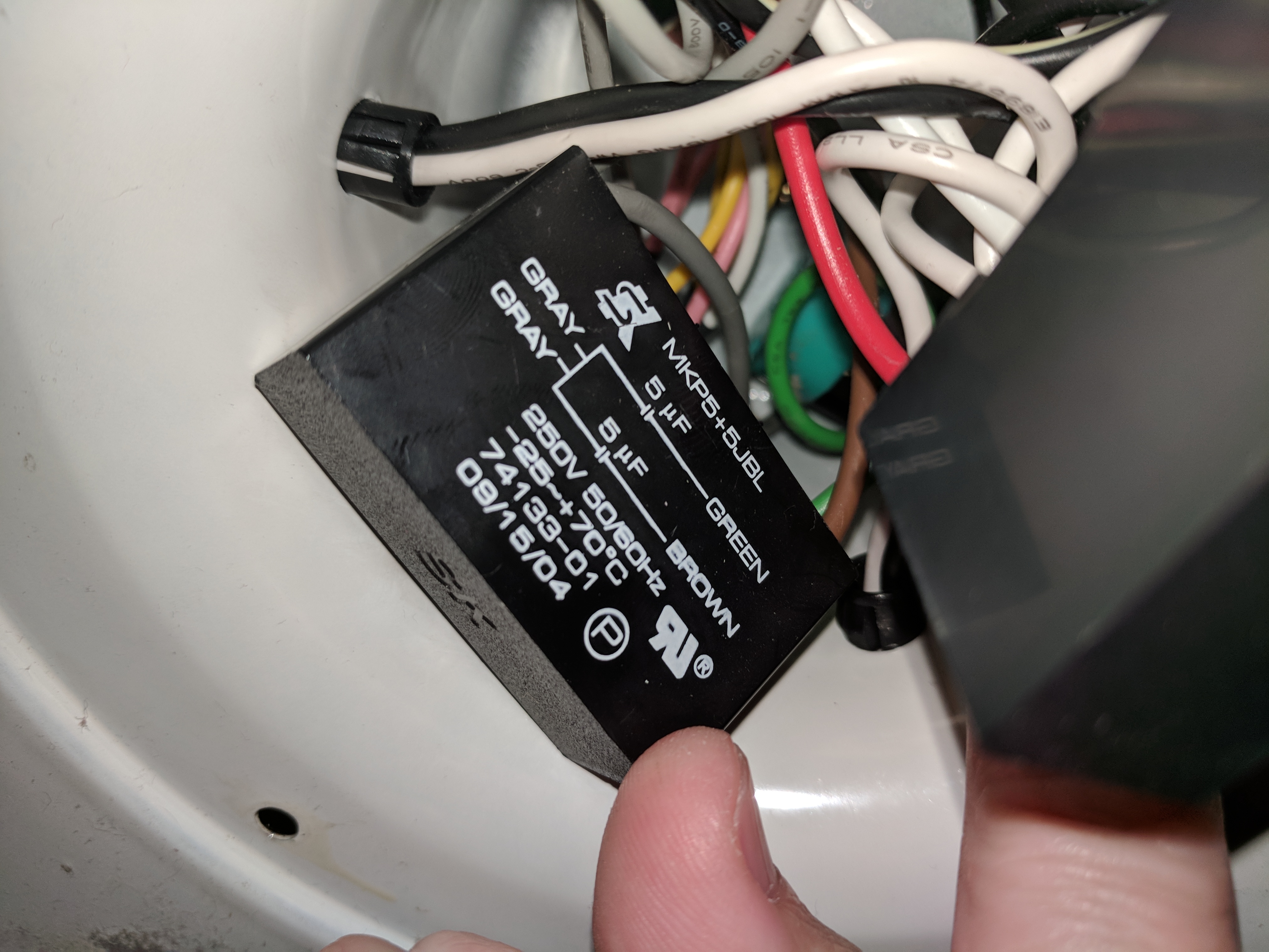
Received mine today and can verify that the light is simply controlled by 1 of the four relays. So it's on/off only as also stated on the ITEAD website. They do mention cold/warm control but that probably only works with a specific light connected to the relay.
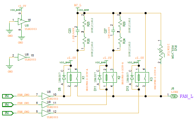
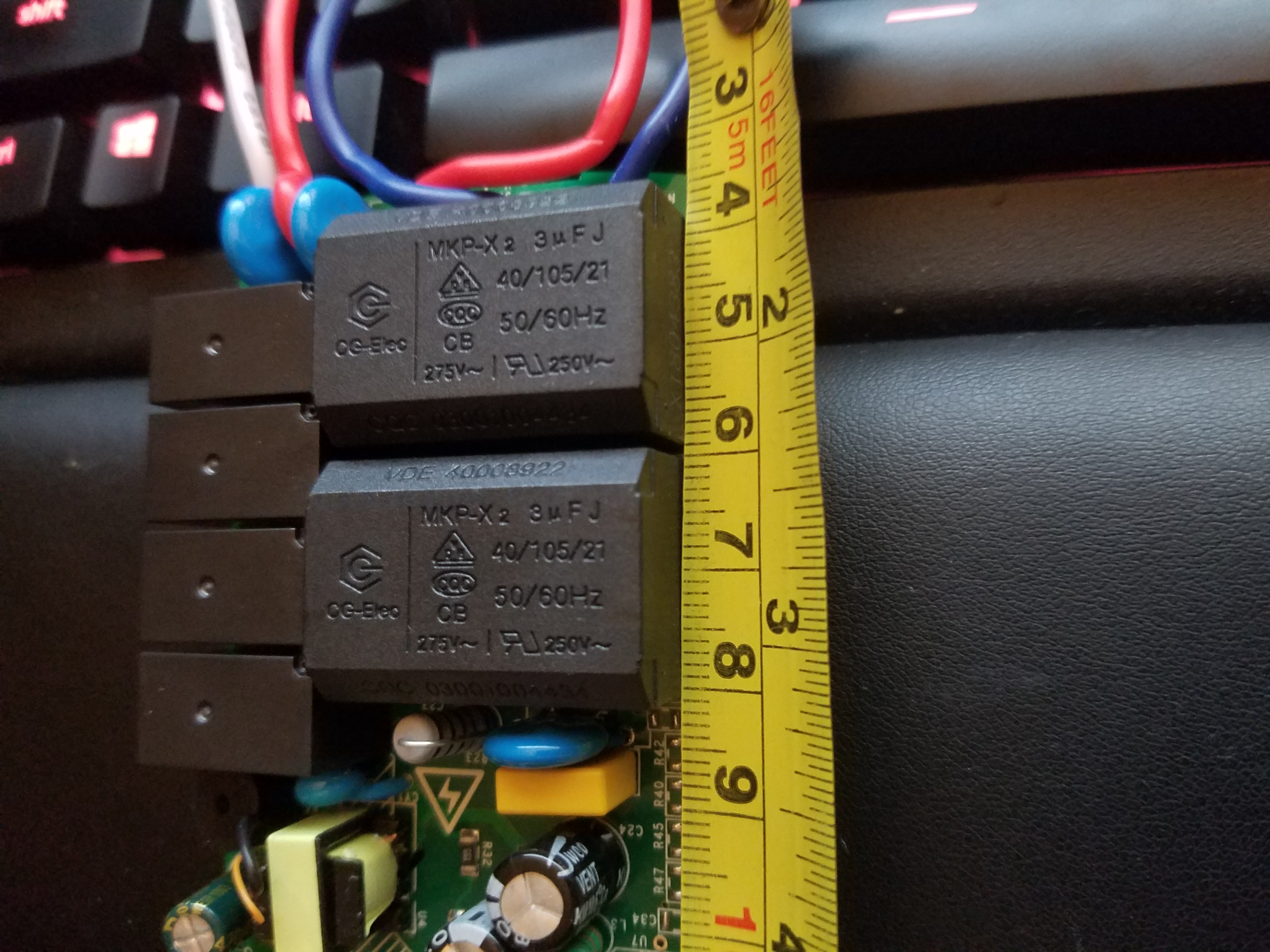
The other three relays control the voltage to the fan; 1 connects power directly and would be fan speed 3, the other two connect power via a 2.5uF capacitor allowing to control the voltage send to the fan. I guess one of the two capacitor relays would make up fan speed 1, both capacitor relays on would be fan speed 2.
I expect control and sequencing is handled by the supporting microcontroller so all I need to do is finding out what GPIOs are used between the esp8285 and the microcontroller...
Stay tuned...
arendst
on 29 Jun 2018
Nice work so far! Definitely going to pull the trigger on this.
My dream for this would be two buttons connected to GPIO pins. One would toggle the light. The other would toggle the fan through the 4 positions. A long press of the fan button would toggle the fan on/off using the last speed as the on state. Firmware doesn't have to do all that as some could be done via the home automation but the rules section might work out as well.
digiblur
on 29 Jun 2018
You all must live closer to China than I do... I'm still waiting...
Snipercaine
on 29 Jun 2018
Mine finally arrived Wednesday, I'm in UK. Would like to thank all you guys for spending the time to get these things working.
Cheers Guys
sleezy100
on 29 Jun 2018
For the light. I guess probably because most ceiling fan/light in China comse with another LED driver inside the light, which you can switch between warm/cold/both. (Since I just finish my installlation last week).
I can take a photo of it, if anyone need it. But I guess it’s nothing to do with ifan02.
 bluefoxlee
on 30 Jun 2018
bluefoxlee
on 30 Jun 2018
Update.
- When connecting AC the light always turns on and the fan always turns off.
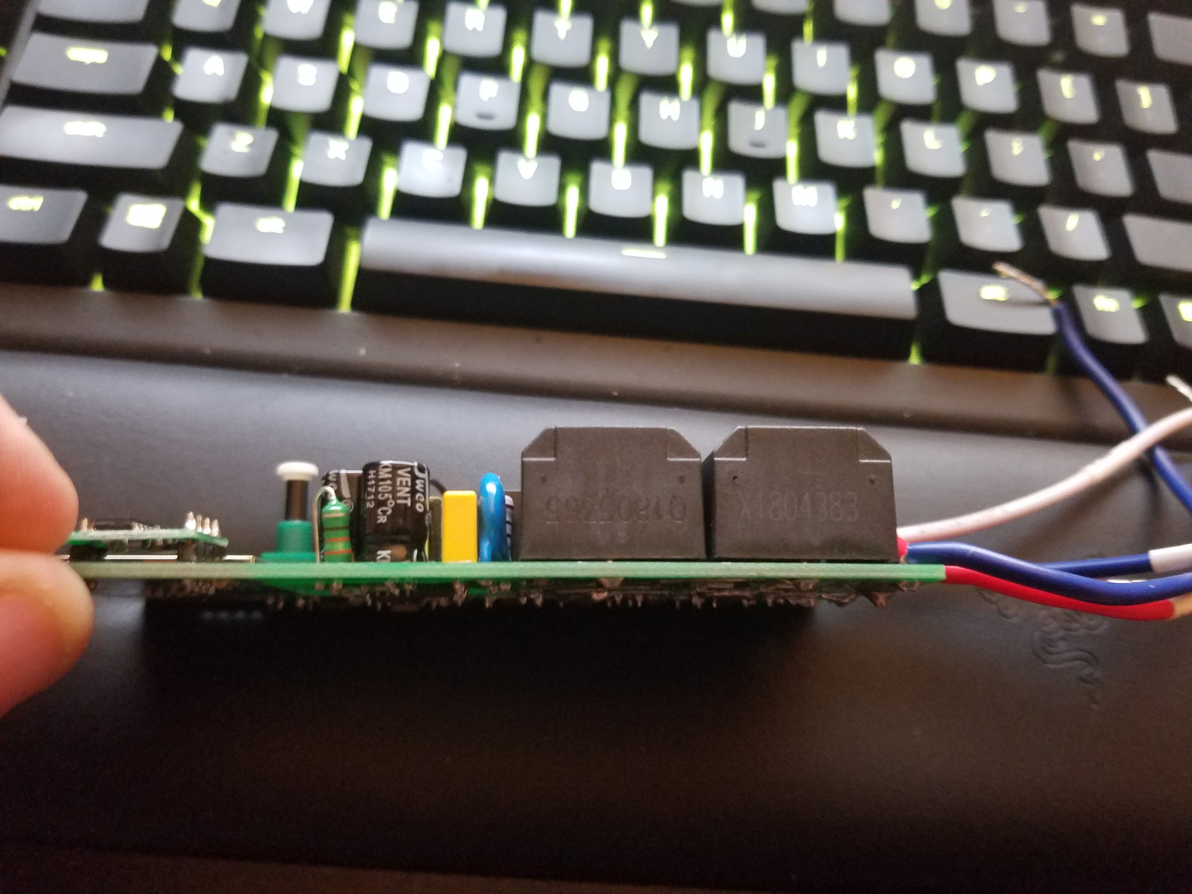
- Powering the thing from a USB to Serial converter doesn't work as it draws too much current.
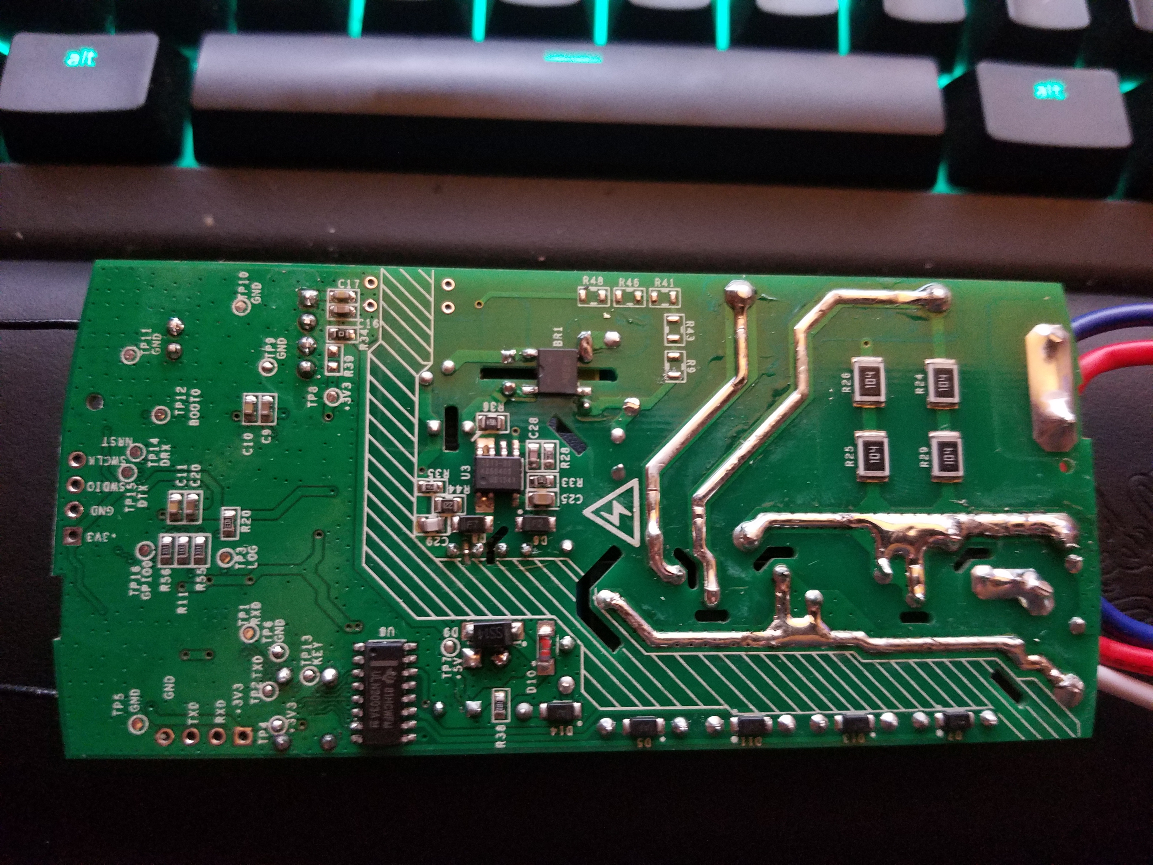
- Gnd does not seem to be connected to AC so I connected my FTDI converter with Gnd,Tx and Rx to J3 and powered it up. No fire, no blows. Seems to be fine as did the Sonoff Basic.
- The button seems to be connected to the microcontroller.
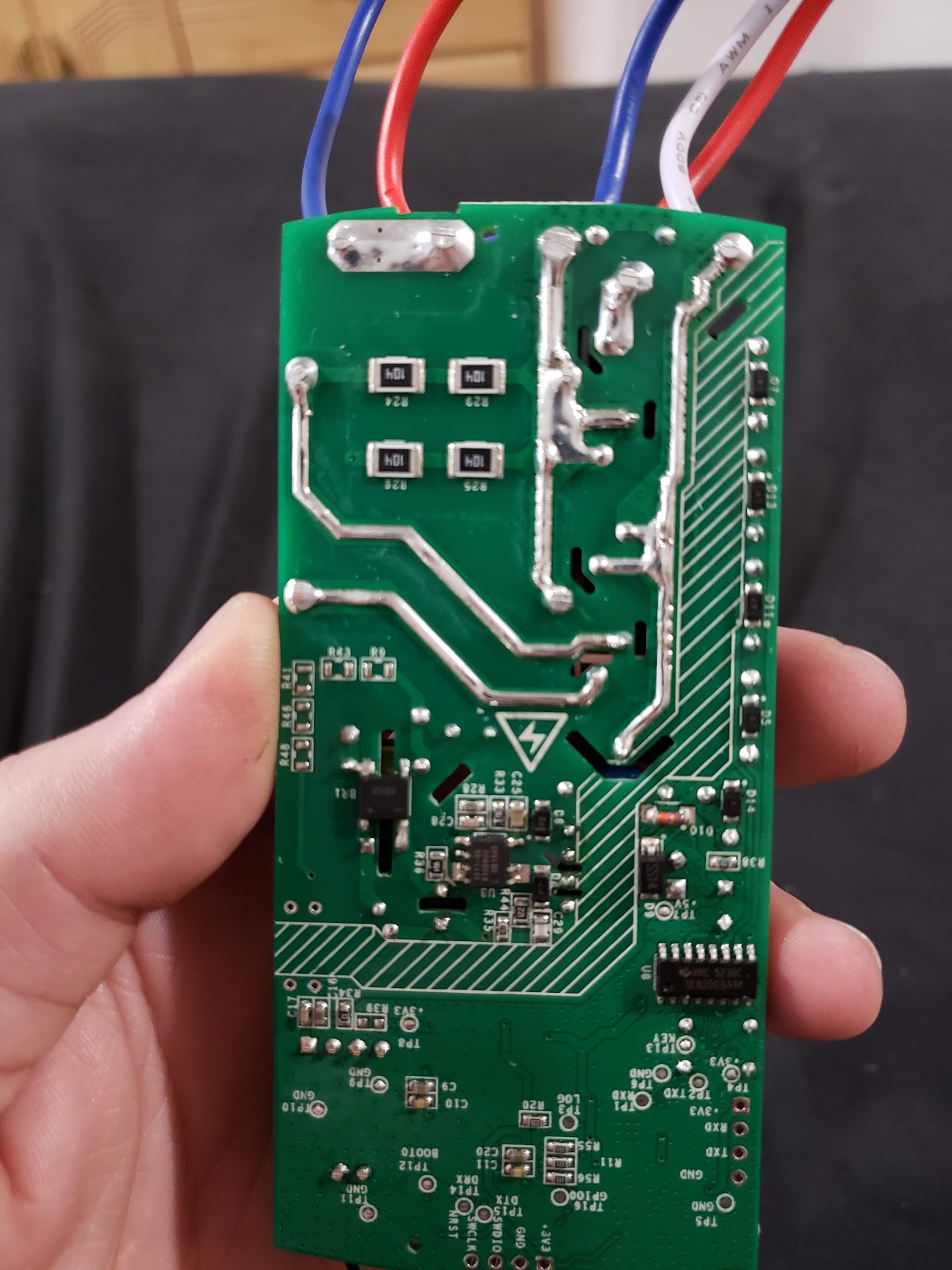
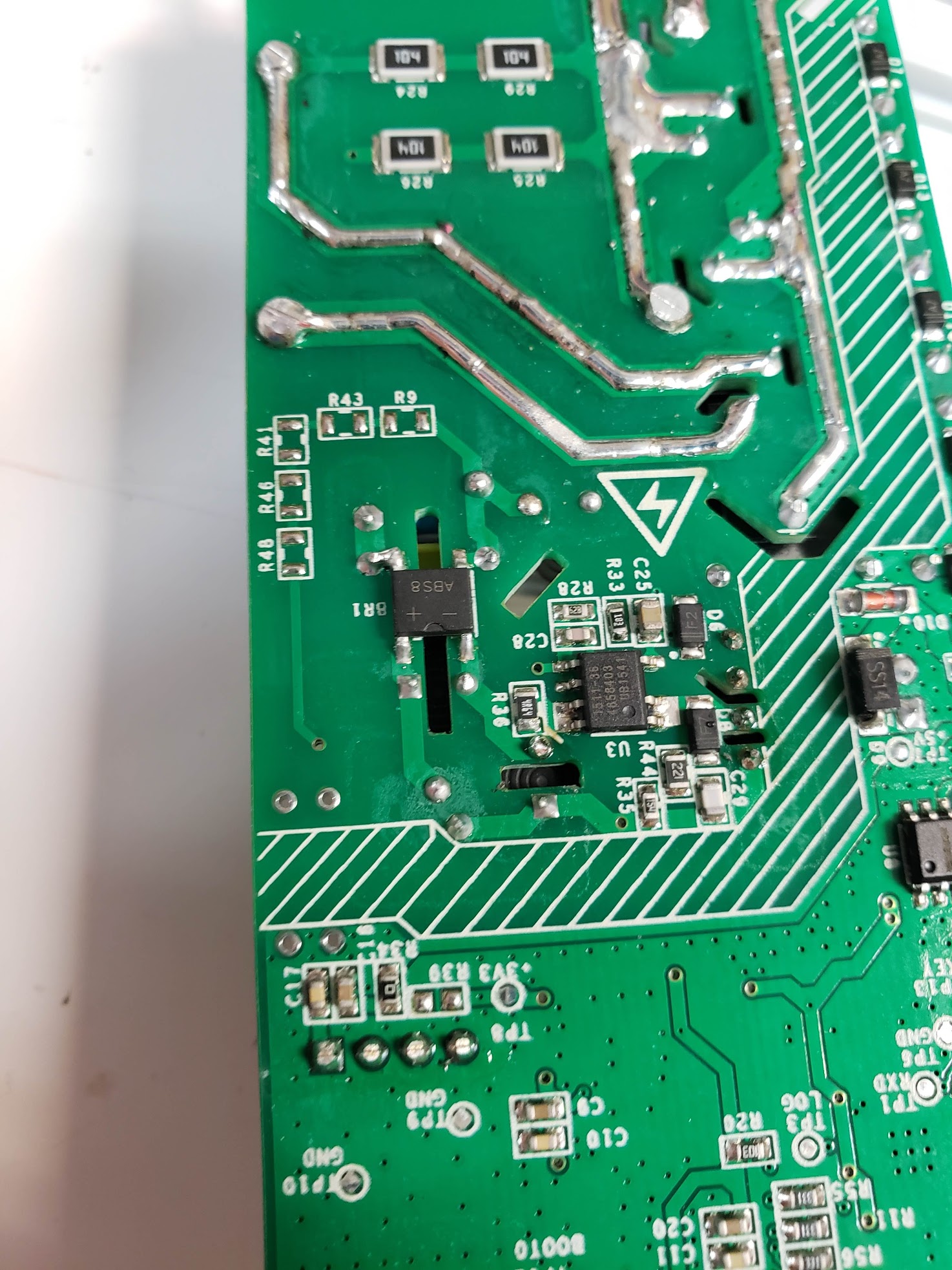
- GPIO00 is accessible as TP16 on the bottom of the PCA. I soldered a wire to it allowing it to connect to Gnd if needed.
- Connecting GPIO00 to Gnd and read-out the 1MB flash went fine.
- While connected GPIO00 to Gnd the remote control is dead so it seems it is either connected to the esp8285 making tasmota integration a bit more difficult or when GPIO00 is low it also disables RF on the microcontroller.
- Connecting GPIO00 to Gnd while running toggles the light relay.
arendst
on 30 Jun 2018
Update.
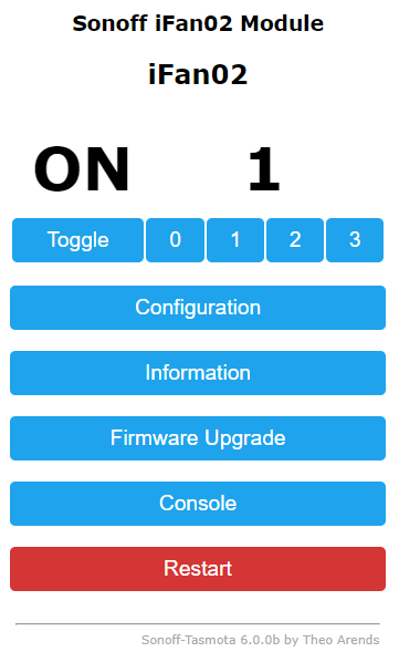
- Flashed tasmota 6.0.0b by grounding gpio00 AND pressing the button at the same time.
- Configured as Sonoff 4CH to see what happens regarding the four relays.
- Oh Joy. The remote still switches the relays as before toggling the 4 relays on the webpage when the different buttons are pressed.
- Need to figure out how to support this with a fan command...
arendst
on 30 Jun 2018
Nice! Looks like I need to get 3 or 4 ordered pretty quickly.
digiblur
on 1 Jul 2018
Release of Sonoff iFan02 in Tasmota.
arendst
on 1 Jul 2018
Thank you
sleezy100
on 1 Jul 2018
Super Work!
Thanks Arenst! I am al ittle bit wary of needing the connection to mains whilst flashing. Unless im reading it wrong, we are going to need extremely detailed instructions for this one!
palitu
on 2 Jul 2018
DrZzs.. Paging DrZzs! I am sure he's already thinking of a video to show on this one.
I only recently ordered mine so it would take me quite a while to get a flashing video out and it would be nowhere in comparison to his video anyways.
digiblur
on 2 Jul 2018
If possible, I would use a bench supply to power it in the instructions
 lorenzop
on 2 Jul 2018
lorenzop
on 2 Jul 2018
Great work Theo (and crew)!
Mine should be here soon. Video not long after.
Am I wrong assuming that we can flash with only the USB/Serial power without connecting mains? As long as we don't activate the relays?
Snipercaine
on 2 Jul 2018
Even with all relays off the USB/Serial converter still is not able to power the device for flashing. A bench supply as opted above should work.
I just my rubber underpants and managed to flash it while connected to AC. Tricky, so I would not advertise it in the video.
arendst
on 2 Jul 2018
It needs 1.21 gigawatts! Great Scott.
Makes sense with the extra hardware drawing too much current for the little USB flasher to power.
digiblur
on 2 Jul 2018
jiga watts...
On Mon, Jul 2, 2018 at 10:06 PM digiblur notifications@github.com wrote:
It needs 1.21 gigawatts! Great Scott.
Makes sense with the extra hardware drawing too much current for the
little USB flasher to power.—
You are receiving this because you commented.
Reply to this email directly, view it on GitHub
https://github.com/arendst/Sonoff-Tasmota/issues/2839#issuecomment-401816682,
or mute the thread
https://github.com/notifications/unsubscribe-auth/AGU9IEiA2L-LlKxEOyJBQfafLsL27Sa-ks5uCijdgaJpZM4UPDk4
.
palitu
on 3 Jul 2018
Depends on your way of spelling but it is pronounced like a J
digiblur
on 3 Jul 2018
HAHAH! What have i started -
https://en.wikipedia.org/wiki/Giga-#Pronunciation
turns out the Yanks started saying it with a soft G in the 60s and 80s.
Potentially should be a hard G due to it being Germanic roots.
Either way - in text land, don't really care about the pronunciation do we!
On Tue, Jul 3, 2018 at 8:03 AM digiblur notifications@github.com wrote:
Depends on your way of spelling but it is pronounced like a J
—
You are receiving this because you commented.
Reply to this email directly, view it on GitHub
https://github.com/arendst/Sonoff-Tasmota/issues/2839#issuecomment-401972969,
or mute the thread
https://github.com/notifications/unsubscribe-auth/AGU9IJNYXem0gXhWVLeT-yQpb4R8TZMPks5uCrTBgaJpZM4UPDk4
.
palitu
on 3 Jul 2018
So, is this working for the fan part? Am looking at buying 7 units to replace my current setup with dumb wall switches and an assortment of basic, low and th... Really miss the ability to change the speed at the moment.
 MimbaMonkeyHouse
on 3 Jul 2018
MimbaMonkeyHouse
on 3 Jul 2018
Are the functions of the remote retained in Tasmota? Thanks for any responses.
 thebradleysanders
on 3 Jul 2018
thebradleysanders
on 3 Jul 2018
Yes, remote works as expected.
arendst
on 3 Jul 2018
Thanks @arendst. Ordere 6 units. You should really get a salary from Sonoff. Thanks for Tasmota!
MimbaMonkeyHouse
on 4 Jul 2018
For those eager to see a schematics of the iFan02 see the wiki at https://github.com/arendst/Sonoff-Tasmota/wiki/Sonoff-iFan02
Courtesy of iTead.
arendst
on 4 Jul 2018
That's awesome you got the schematic! Exactly what I wanted. Saves me from ohming stuff out when I get mine to see what is what when adding pull up resistors and such.
digiblur
on 4 Jul 2018
Dumb questions probably but I'm not a prior Tasmota user....
I see the remote still works - great!
I assume the device is also controllable via a MQTT message? And that the status is sent via an MQTT message also?
So if I turn on/off the light or change fan speeds I can sniff the MQTT messages to get the actual status? And send an MQTT message to change the status?
 finity69x2
on 4 Jul 2018
finity69x2
on 4 Jul 2018
Take a look at the console and see what messages are being sent. Should be pretty easy to figure the command messages of the console messages.
digiblur
on 4 Jul 2018
@finity69x2 Yep.
arendst
on 4 Jul 2018
@digiblur
I haven't odered any yet.
I just wanted to make sure that I knew what to expect before I did order any.
I've been burned before on my literally year long quest to try to find a Home Assistant compatible Fan/light controller! Hunter fans are ridiculously difficult to properly integrate.
finity69x2
on 4 Jul 2018
Awesome!
I just dropped the hammer and ordered a few.
Hopefully the wife won't drop the hammer on me! :)
finity69x2
on 4 Jul 2018
Hey Theo. Impeccable work.
Got two yesterday and set about flashing. I'm actually using ESPTool just because I'm familiar with it. I made a few bonehead mistakes that might help others. I started working with the J2 header and I thought that I was getting garbage on the serial, but not really. Once I did the correct wiring to the J3 header, comms were up!
My uploads were failing at about 30%. I cut the baudrate and this was my command
esptool.py -b 74880 --port /dev/ttyUSB0 write_flash -fs 1MB -fm dout 0x0 sonoff.bin
Still had trouble so I hooked the VCC back up in addition to mains power (rubber undies :) ) and that solved it completely. Configured as 4 Ch and just like you said, worked like a charm with the remote and through the tasmota web interface.
Once I get a binary or compile my own, I'll convert it over to your actual ifan2 module configuration.
I really appreciate your efforts. You have created an operating system that runs on a light switch. Amazing.
UPDATE: Compiled my own binary and it is a thing of beauty. Will get installed tomorrow morning.
 jumblies
on 4 Jul 2018
jumblies
on 4 Jul 2018
I can see from the schematic that there is a zero line detector, but i cannot see where it would be used. I would have imagined that it is used for a triac for light dimming, but there doesn't seem to be anything obvious.
any ideas?
palitu
on 5 Jul 2018
Okay, this is a EE question, not a tasmota question at all.
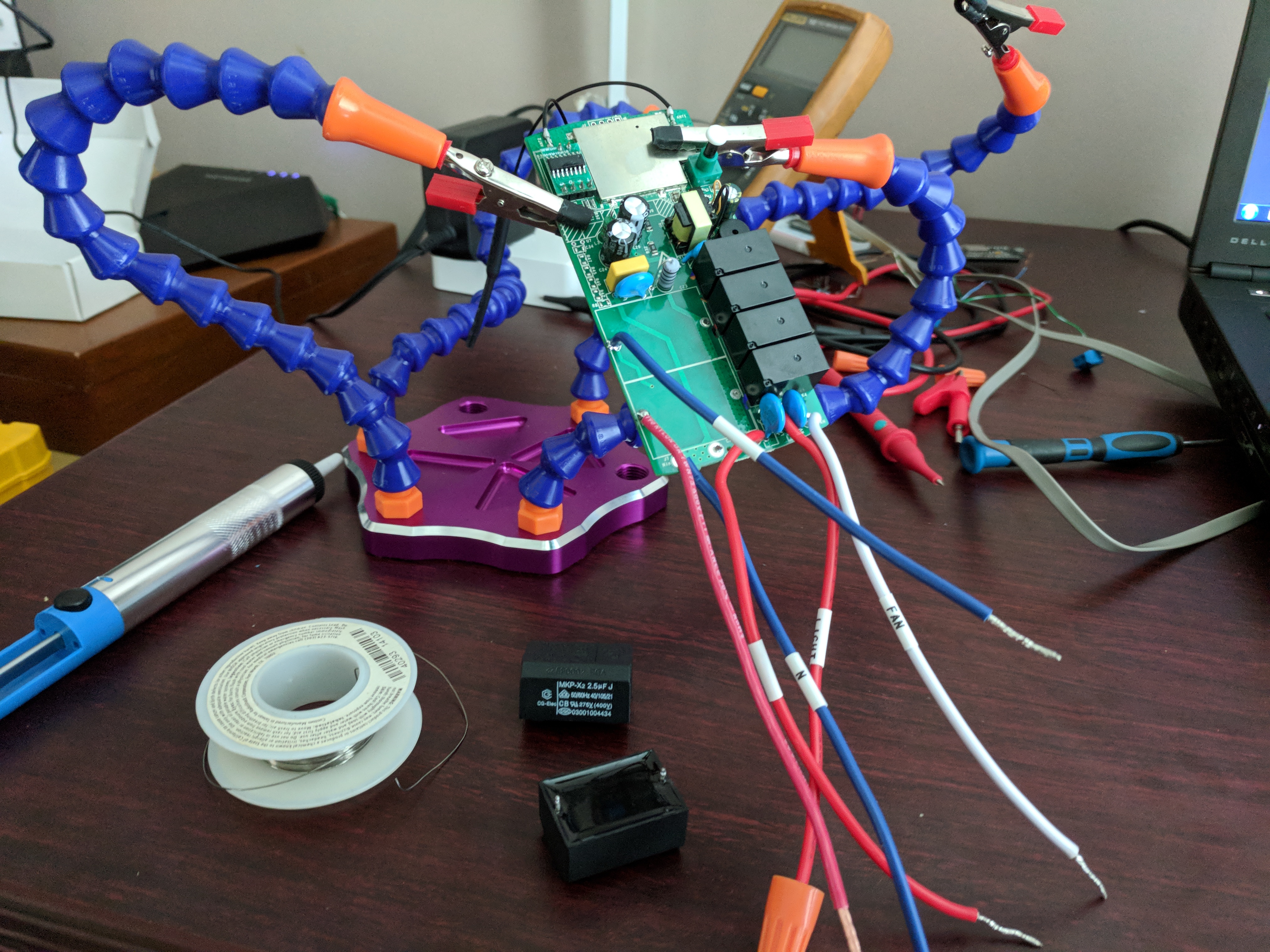
Hooked it up upstream of the fan wiring (going into the fan where the pull chain resides)
- speed 1, it is way too slow, estimate 30 rpm (w/o iFan02, prob double that)
- speed 2, passable as low
- speed 3, faster than normal; very windy
My understanding is that increasing capacitance in AC circuits increases the power factor and that explains the faster than normal, but I'm trying to wrap my head around how to fix the other two speeds. I'm guessing this is meant to work on a single speed fan with no other capacitance than supplied by the iFan02.
Anyone have any ideas?
I'd consider:
- Wiring tasmota fan directly to fan motor coil but this loses reverse functionality, I think.
- bypassing the pull chain switch and associated fan housing capacitor
BTW: It works fine as a fan component in homeassistant but speed selection is a little clunky on the UI. Will work on that later.
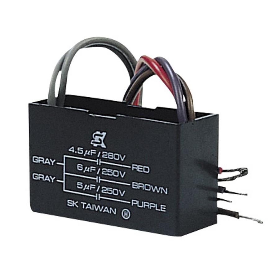
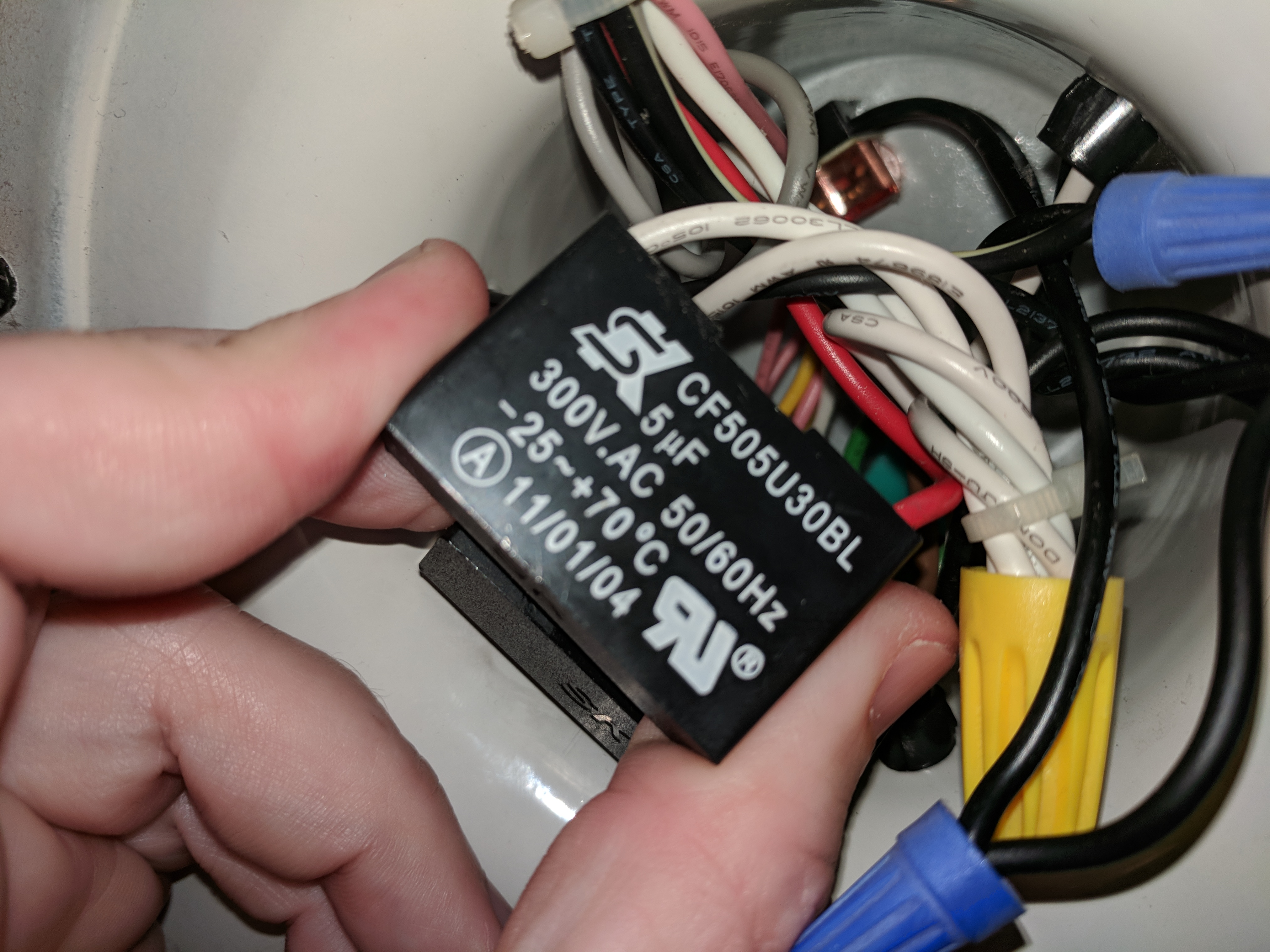
Shown below is the capacitor that is in the fan.
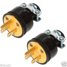
A tip for flashing on AC use a plug end like this: I had one lying around but didn't think of it until later.
jumblies
on 5 Jul 2018
I thinnk that these drivers ore supposed replace the existing driver / caps in your wall switch / fan.
- for a wall controlled one, you should replace the wall controller with an on/off switch, and have this as the only controller for the fan.
- For a fan which isn't controlled by the wall, potentailly added in after and uses a remote to control it, you should find the driver in the fan housing it self, and replace the OEM one with this.
If you have both, you will get weird functionality/speeds.
Only use one controller - this or the original, not both!
palitu
on 6 Jul 2018
Do you release the button AND disconnect GPIO00 after applying AC to enter it into programming mode? Is there an led indication that it is in programming mode and ready to be flashed?
 mustangarcher
on 6 Jul 2018
mustangarcher
on 6 Jul 2018
Having just done my second, yes. I do this. Short 0, and hold the button
down, pub in usb (or apply power to uart) then hit AC mains power.
On Jul 6, 2018 11:05, "mustangarcher" notifications@github.com wrote:
Do you release the button AND disconnect GPIO00 after applying AC to enter
it into programming mode? Is there an led indication that it is in
programming mode and ready to be flashed?—
You are receiving this because you commented.
Reply to this email directly, view it on GitHub
https://github.com/arendst/Sonoff-Tasmota/issues/2839#issuecomment-403061144,
or mute the thread
https://github.com/notifications/unsubscribe-auth/AXFbv6aJ4iBi8bbIpuIxScYPn3DJYmcCks5uD3zQgaJpZM4UPDk4
.
jumblies
on 6 Jul 2018
Because I needed three arms and wasn't willing to wait for CRISPR to work,
used a foot switch.
On Jul 6, 2018 11:10, "Geoff L" glamke@gmail.com wrote:
Having just done my second, yes. I do this. Short 0, and hold the button
down, pub in usb (or apply power to uart) then hit AC mains power.On Jul 6, 2018 11:05, "mustangarcher" notifications@github.com wrote:
Do you release the button AND disconnect GPIO00 after applying AC to
enter it into programming mode? Is there an led indication that it is in
programming mode and ready to be flashed?—
You are receiving this because you commented.
Reply to this email directly, view it on GitHub
https://github.com/arendst/Sonoff-Tasmota/issues/2839#issuecomment-403061144,
or mute the thread
https://github.com/notifications/unsubscribe-auth/AXFbv6aJ4iBi8bbIpuIxScYPn3DJYmcCks5uD3zQgaJpZM4UPDk4
.
jumblies
on 6 Jul 2018
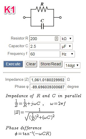
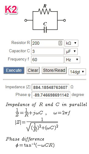
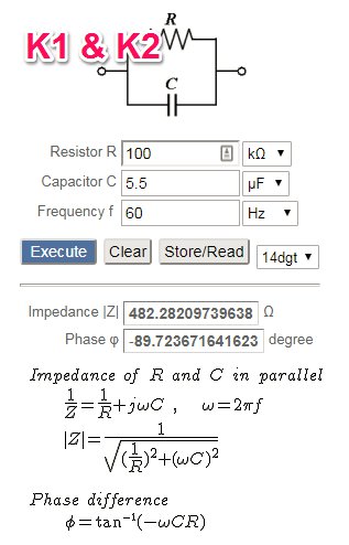
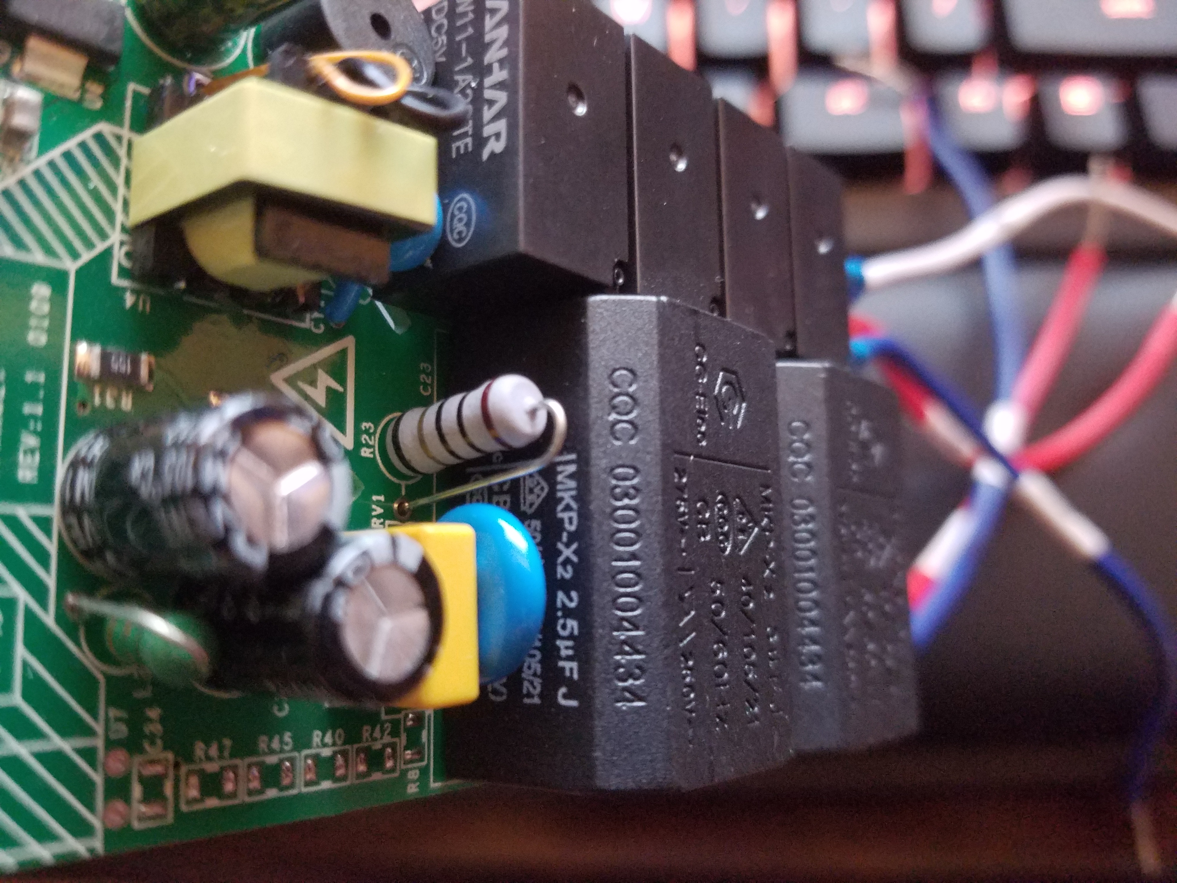
@palitu is on to something. K1 and K2 drop in parallel RC circuits to change the impedance of the line. This circuit is likely the same design as the one in the fan. Adding it in line with it would have unexpected interactions.
Changing the output impedance is a more efficient way to control the fan output because it doesn't create as much heat as using a resistor bank.
Looking at the circuit, I wonder if K1 is low speed, K1 and K2 is medium, and K3 high? The RC banks on 1&2 are different, but not so much looking at them individually. I'm going to need to order one and bench test it as stock with a fan.
 vequalsir
on 6 Jul 2018
vequalsir
on 6 Jul 2018
@vequalsir you're right regarding which relay (pair) does amount to what speed. In fact, for the adventurous ones, if you change the module from 44 (iFan02) to 07 (4CH) then when you select the different speeds using the remote control you'll see which relay is activated at what speed. For the iFan I've hidden this information ;-)
Note1: iTead leaves K1 always on from speed 1 to 3. No problem as K3 will short K1 anyway at full speed.
Note2: What are we talking about? This:
arendst
on 6 Jul 2018
I see exactly what he's talking about. I don't understand it well enough to know how to proceed with wiring it up with an american style 3 speed fan. I tried a couple of different combinations today before a pause to try to understand it more. None of the combos with the ON FAN capacitor bank, reverse switch and speed switch removed provided adequate function.
I did derive that the white + pink combo provides forward while white plus yellow is reverse. It gives me an inkling that I can tie those for direction easy enough but I'm stymied by the speed control part.
jumblies
on 6 Jul 2018
I get an error compiling version 6.0.0c. "Error compiling for board ESP8266 Module." I have tried changing the board manager to ESP8265 and NodeMCU. All get compile errors.
mustangarcher
on 6 Jul 2018
Having extra capacitors in series is surely going to screw up the speeds, I think in 'full speed' mode most fans bypass the run capacitors and just pass mains straight to the run winding, then this device can switch in one or both of the capacitors on board for speed control. When I replace my fan switches with these I intend to desolder the ifan02's capacitors and solder on the ones my fan came with, thus preserving the same speeds it originally had, because if the capacitors don't match then of course you'll get 'too slow' or 'too fast' speeds.
abzman
on 6 Jul 2018
That was my intention as well. Remove the pull string for speed and leave it on full. Curious to see if I have to mod the other speeds.
digiblur
on 6 Jul 2018
@abzman abzman you are 100% correct, about it messing up the speeds but it's not as simple as plugging mains current into one wire. The fans use a motor with dual windings and offset in the phase to control the amount of torque and speed by setting the the "slip". I spent a day reading uncommonly civilized discussions on stackexchange to get the general picture. It's actually kinda weird that there is a ceiling fan in almost every home, but little discussion of their functioning internals. I guess that what happens when a product just works.
In short, just plugging Hot and Neutral doesn't give you full speed on my model(Harbor Breeze Hunter Clone). Please let me know what your experiments show. I think what you propose might partially work, but it's not a "drop in" cap exchange.
jumblies
on 6 Jul 2018
@mustangarcher what platform are you compiling on? I struggled initially with tasmota on PIO but then I actually read the manual and it compiled. Oh, and if you are in a hurry, you can use ESPtool to flash a compliled bin and config it as a 4CH relay as described above by the man @arendst himself.
jumblies
on 6 Jul 2018
I am using the arduino 1.8.5. I would really rather use the latest tasmota version with the ifan02 module rather than the 4CH so that the user interface is intuitive for use with the fan. I don't want to have to turn on 2 relays to achieve medium speed.
mustangarcher
on 6 Jul 2018
@mustangarcher you're in luck, check the releases tab.
digiblur
on 6 Jul 2018
Question here: If I bypass the ifan02 module so that the remote does not turn off the power to my lights, can tasmota still announce the remote button press over MQTT? I would like to retain the on/off function for the lights using the remote through Home assistant, but I do not want the ifan02 actually cutting the power to my smart bulbs.
 roofuskit
on 7 Jul 2018
roofuskit
on 7 Jul 2018
Yes I believe Tasmota will retain the state of the light regardless if it is wired in or not. The only thing that could change with behavior is to detect the load to determine the sate. Use the light state topic to control your smart lights lights in Home assistant.
thebradleysanders
on 9 Jul 2018
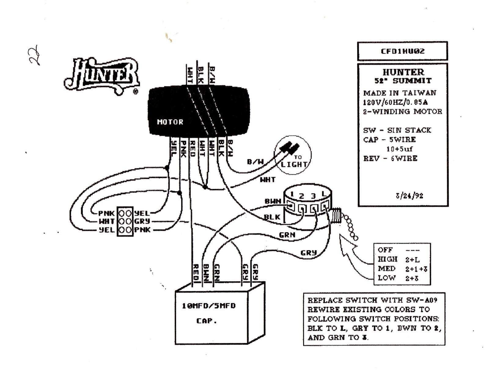
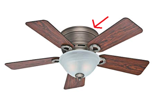
To directly answer @jumblies - assuming the diagram you provided is correct, you will need to use _part_ of your existing capacitor. Wire the FAN_L to the gray wire going to the direction switch, keep the capacitor wired in place, put the pull switch in the OFF position. The capacitor values are different, so speeds will be different than stock.
If you want to completely remove the pull switch:
- Pull the black wire off the switch and feed into Itead.
- Remove and cap off the green and brown wires on the capacitor to prevent shorts.
- Put the FAN_L to the gray wire from the switch/to the capacitor.
Speed selection should then be:
- High speed is FAN_SW2,
- Medium is FAN_SW0 and FAN_SW1,
- Low is FAN_SW0 or FAN_SW0 (depends on which "low" speed you like better).
Try that and let me know if it works!
 jeepnjonny
on 11 Jul 2018
jeepnjonny
on 11 Jul 2018
@jeepnjonny I just tried your suggestion. Same behavior as before. I completely disconnected the pull switch.
to reiterate behvior:
- 3 / High = same as original wiring
- 2 / Med = original 1
- 1 / Low = crawl
- Hot/Black to iFan02
- FAN_L to Grey on Cap
Left reveresal switch alone
Pull chain is removed and sitting on my desk.
Just for giggles, I hooked it up to AC exhaust fan in my garage. It was even worse and only functioned on speed 3, but that is almost certainly because it's a continuously variable speed fan.
jumblies
on 11 Jul 2018
It's functionally wired correctly, but the capacitor values are different enough to not work with the windings in your fan. Your original capacitors were Grn at 5uF (530.5Ω) for Low, Grn+Brn at 11uF (241.1Ω) for Medium, and 0uF (0Ω)for High. Itead has K1 at 2.5uF (1061.0Ω), K2 at 3uF (884.1Ω), K1+K2 at 5.5uF (482.2Ω). It makes sense that the Itead medium is similar to the original Low, as they are close in impedance. Otherwise their capacitors are half the value of your originals.
It might have been better if Itead designed their controller to use an external capacitor so it would simply replace the speed selector switch and each fan motor could be matched with the right capacitors. Looking at the pictures in this thread, it should be possible to replace the capacitors or hook up your original capacitors to get the same speeds.
jeepnjonny
on 11 Jul 2018
Thanks for your analysis. It's the same conclusions I came to as well.
I'm not ready to pull apart the ifan to swap the caps.
It makes me wonder whether fans in other locales have just a single winding
and place the speed control caps in the wall switch or use another
mechanism for speed control, leading to iteads design decision.
It seems doubtful that they could pick uniform capacitor values and have
then work universally.
I still think it's a good value for RF and Wi-Fi control, neither of which
I had before. And it opens the door to automation. For example, I want
one to turn on automatically when I'm on the exercise bike. Haven't
decided whether to use a BME280 to sense temp/humchange, ultrasonic, or
other sensor to automate it yet.
That's what's great about tasmota. I can use one or a few, or none and
don't have change any code. Having written a dozen mqtt custom sensors,
tasmota is vastly superior to any of my own.
On Jul 11, 2018 16:23, "jeepnjonny" notifications@github.com wrote:
It's functionally wired correctly, but the capacitor values are different
enough to not work with the windings in your fan. Your original capacitors
were Grn at 5uF (530.5Ω) for Low, Grn+Brn at 11uF (241.1Ω) for Medium, and
0uF (0Ω)for High. Itead has K1 at 2.5uF (1061.0Ω), K2 at 3uF (884.1Ω),
K1+K2 at 5.5uF (482.2Ω). It makes sense that the Itead medium is similar to
the original Low, as they are close in impedance. Otherwise their
capacitors are half the value of your originals.It might have been better if Itead designed their controller to use an
external capacitor so it would simply replace the speed selector switch and
each fan motor could be matched with the right capacitors. Looking at the
pictures in this thread, it should be possible to replace the capacitors or
hook up your original capacitors to get the same speeds.—
You are receiving this because you were mentioned.
Reply to this email directly, view it on GitHub
https://github.com/arendst/Sonoff-Tasmota/issues/2839#issuecomment-404298238,
or mute the thread
https://github.com/notifications/unsubscribe-auth/AXFbv9m-dIeMYANNkcxOp9Y079jvl5_Tks5uFl7dgaJpZM4UPDk4
.
jumblies
on 12 Jul 2018
Mine bricked after updating to 6.1.0 issue raised here #3202
 donoo
on 13 Jul 2018
donoo
on 13 Jul 2018
@donoo pretty hard to brick a esp chip unless you try. Is it alive via serial?
digiblur
on 13 Jul 2018
@digiblur I used SonOTA to update it. I did not check via serial as for this module it is not straight forward, as mentioned in the support page I have to use live AC power which I m not confident to do :(
If there are some instructions anywhere then I will try on my raspberry pi.
donoo
on 13 Jul 2018
Right but that's all I know to do unless you can factory default some how through a button config.
Solder two pins in on TX/RX and run them out the case. Triple check it is TX/RX. Close it and fire it up.
Edit: also run GND
digiblur
on 13 Jul 2018
@digiblur thanks for quick reply, is there anywhere screen shot with TX/RX marked on board. That will give me confidence to flash it via serial.
donoo
on 13 Jul 2018
@donoo Yep, scroll back up and you'll see someone posted a picture of the bottom of the board, it is printed right on the board for you.
As noted up above, just like with any Sonoff device, NEVER connect to the 3v3 power to flash while you have mains power connected. Expect the magical smoke to be released and possibly other things.
digiblur
on 13 Jul 2018
@donoo
Sorry to hear about the problems. I was able to use Program Version | 6.0.0c flashed over serial
on my 2 iFan02's. Maybe that version will help after you recover over serial. People have successfully flashed without soldering with pogo pins, but most people don't have them lying around. If you need a binary, let me know and I'll compile one for you, just let me know what wifi method you want to default to.
soldering the headers on is straightforward. Headers on top with the rest of the components. Try to alligator clip in place or use blu tack, then flip it over and solder it up.
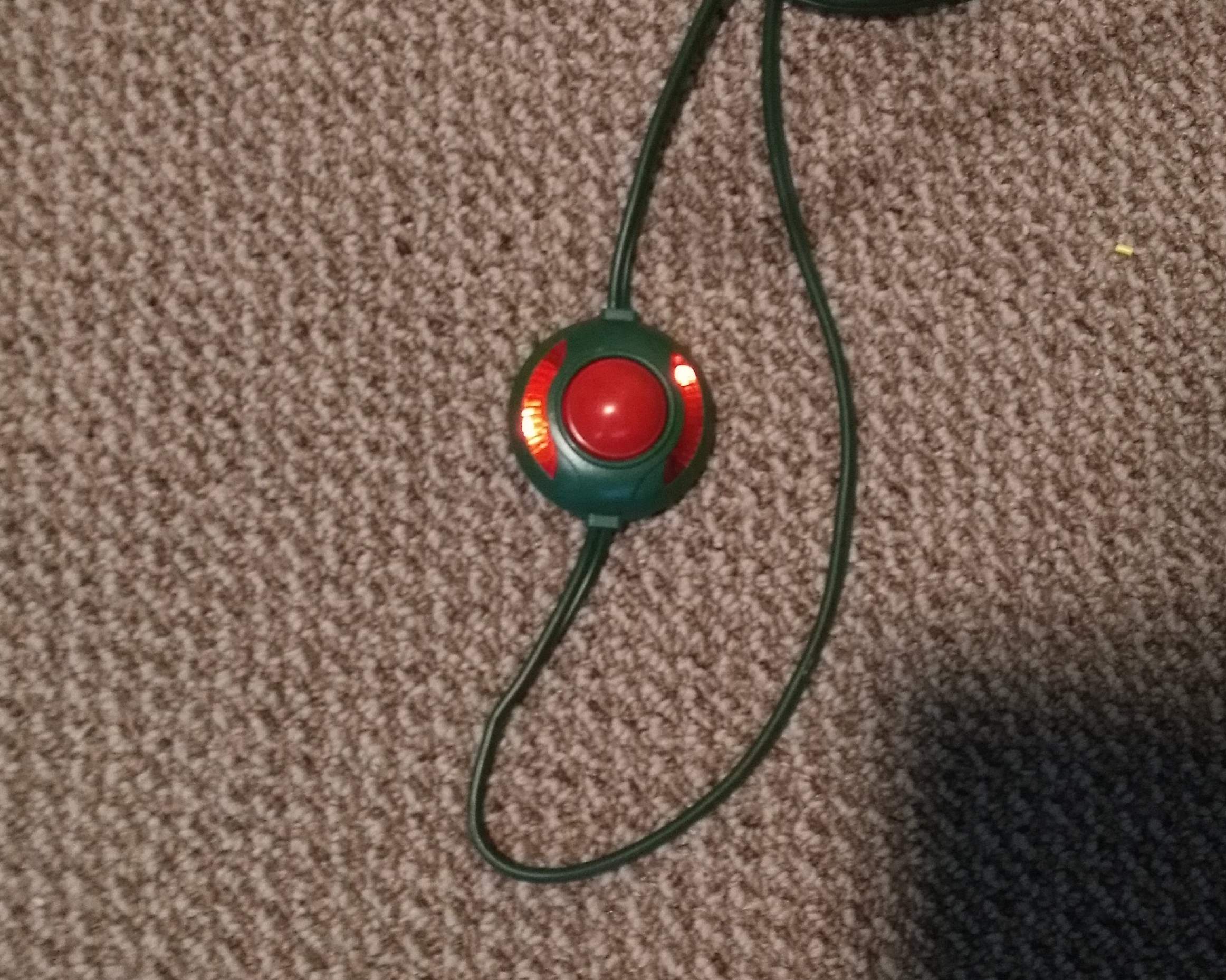
I posted a pic above of a plug but I originally just used a christmas light foot switch with the line in wires jammed in it, but I don't recommend that. It's a lot of stuff to juggle.
jumblies
on 13 Jul 2018
@jumblies Thanks for the reply! Will try this version once I m able to flash it over serial. Will update here with results.
donoo
on 13 Jul 2018
I edited my post earlier. Don't forget ground as well for TX RX
digiblur
on 13 Jul 2018
My pleasure. I think we all know how incredibly frustrating it is to get a
new device and immediately hit a wall.
On Jul 13, 2018 14:54, "donoo" notifications@github.com wrote:
@jumblies https://github.com/jumblies Thanks for the reply! Will try
this version once I m able to flash it over serial. Will update here with
results.—
You are receiving this because you were mentioned.
Reply to this email directly, view it on GitHub
https://github.com/arendst/Sonoff-Tasmota/issues/2839#issuecomment-404922163,
or mute the thread
https://github.com/notifications/unsubscribe-auth/AXFbvw0sp6sQTQTaH_yZrTwpH554Eyf0ks5uGOzQgaJpZM4UPDk4
.
jumblies
on 13 Jul 2018
@jumblies Need one help. What does this mean? Do I have to solder extra wire ?
The button is not connected to GPIO00 so flashing the unit requires some extra work. I managed to flash the iFan02 by soldering a wire to TP16 (GPIO00) on the bottom of the PCA. While connecting this wire to Gnd and also keeping the button pressed when applying power to the unit it will be in firmware upgrade mode.
I have added header pins on J3 but not sure about this one.
donoo
on 14 Jul 2018
That is correct. If you can stick something to TP16 (Test Point 16) that
would work. I soldered some fine wire and it worked great on my first
one. I grounded it to the GND on the UART serial adapter. You can jumper
it any ground you can find to the serial adapter, including the GND pin on
the sonoff if you want.
My second one the pad at TP16 lifted and I couldn't recover that trace so I
had to get creative. If it comes to that, we can discuss but I think gentle
handling of the wire and a spot of glue after you solder it is probably the
best thing. Plan on leaving the wire there and insulating it so it
doesn't short.
It kinda requires 3 or 4 hands but you can do it.
On Sat, Jul 14, 2018 at 8:39 AM, donoo notifications@github.com wrote:
@jumblies https://github.com/jumblies Need one help. What does this
mean? Do I have to solder extra wire ?The button is not connected to GPIO00 so flashing the unit requires some
extra work. I managed to flash the iFan02 by soldering a wire to TP16
(GPIO00) on the bottom of the PCA. While connecting this wire to Gnd and
also keeping the button pressed when applying power to the unit it will be
in firmware upgrade mode.I have added header pins on J3 but not sure about this one.
—
You are receiving this because you were mentioned.
Reply to this email directly, view it on GitHub
https://github.com/arendst/Sonoff-Tasmota/issues/2839#issuecomment-405021242,
or mute the thread
https://github.com/notifications/unsubscribe-auth/AXFbv9gujLb_LYdNaMMvqEG2QII0Yk5jks5uGeaJgaJpZM4UPDk4
.
--
“The best way to predict the future is to design it.” —Buckminster Fuller
jumblies
on 14 Jul 2018
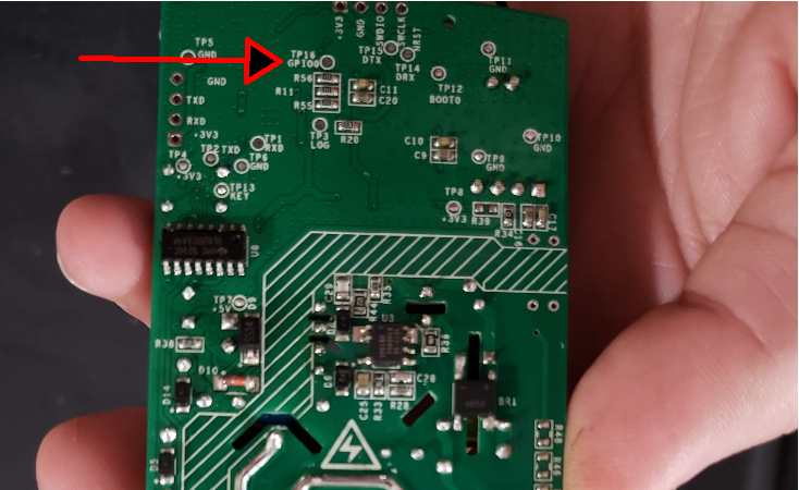
That's your TP16. I grabbed the pic above, rotated and arrowed it. Many thanks to @abzman for the thorough layout pics.
jumblies
on 14 Jul 2018
@jumblies Thanks for the quick reply. I m using Raspberry Pi 3 for Serial flash. I have flashed all previous Sonoff Devices using SonOTA. This is first time I m having issues.
Let me try this.
donoo
on 14 Jul 2018
I didn't even know you could use a pi! As Rorschach said "obvious, really"
since even an arduino can do it.
If you're inclined, you might pick up a pair of ftdi and cp2102 adapters
from aliexpress. I keep both but they're interchangeable. Somebody once
suggested to me to get some and if you're going to hack something, just
leave it there. They are cheap and very useful for serial debug. I'm
talking modems, routers, sonoffs, IP cams and other embedded hardware.
On Jul 14, 2018 9:59 AM, "donoo" notifications@github.com wrote:
@jumblies https://github.com/jumblies Thanks for the quick reply. I m
using Raspberry Pi 3 for Serial flash. I have flashed all previous Sonoff
Devices using SonOTA. This is first time I m having issues.Let me try this.
—
You are receiving this because you were mentioned.
Reply to this email directly, view it on GitHub
https://github.com/arendst/Sonoff-Tasmota/issues/2839#issuecomment-405025428,
or mute the thread
https://github.com/notifications/unsubscribe-auth/AXFbv3I919B3W1-bvHYP1ekdTwcoDB9Iks5uGfkygaJpZM4UPDk4
.
jumblies
on 14 Jul 2018
Seems I kind of messed GPIO0 , not able to connect to device.
`
esptool.py v2.4.1
Serial port /dev/ttyS0
Connecting........_____....._____....._____....._____....._____....._____....._____
A fatal error occurred: Failed to connect to Espressif device: Timed out waiting for packet header
`
Getting following error.
Connected GRN , TX and RX on J3 but I m not able to connect to device
donoo
on 14 Jul 2018
It's tricky to get the sequence. You have to apply power to the chip
through the serial adapter first while holding button plus gpio0 to ground
and then you can apply AC. I suspect it isn't entering flash mode based on
lack of response. I had to try a few permutations to get it right.
On Jul 14, 2018 12:19, "donoo" notifications@github.com wrote:
Seems I kind of messed GPIO0 , not able to connect to device.
`
esptool.py v2.4.1
Serial port /dev/ttyS0
Connecting......................................_____A fatal error occurred: Failed to connect to Espressif device: Timed out
waiting for packet header
`Getting following error.
—
You are receiving this because you were mentioned.
Reply to this email directly, view it on GitHub
https://github.com/arendst/Sonoff-Tasmota/issues/2839#issuecomment-405033693,
or mute the thread
https://github.com/notifications/unsubscribe-auth/AXFbv4UuGNshWDQmpNB762ikGI1C5Qk-ks5uGhongaJpZM4UPDk4
.
jumblies
on 14 Jul 2018
Once you power it up you can release everything. I don't think it will
flash if everything is pressed while you try to communicate with it.
On Jul 14, 2018 12:23, "Geoff L" glamke@gmail.com wrote:
It's tricky to get the sequence. You have to apply power to the chip
through the serial adapter first while holding button plus gpio0 to ground
and then you can apply AC. I suspect it isn't entering flash mode based on
lack of response. I had to try a few permutations to get it right.On Jul 14, 2018 12:19, "donoo" notifications@github.com wrote:
Seems I kind of messed GPIO0 , not able to connect to device.
`
esptool.py v2.4.1
Serial port /dev/ttyS0
Connecting......................................_____A fatal error occurred: Failed to connect to Espressif device: Timed out
waiting for packet header
`Getting following error.
—
You are receiving this because you were mentioned.
Reply to this email directly, view it on GitHub
https://github.com/arendst/Sonoff-Tasmota/issues/2839#issuecomment-405033693,
or mute the thread
https://github.com/notifications/unsubscribe-auth/AXFbv4UuGNshWDQmpNB762ikGI1C5Qk-ks5uGhongaJpZM4UPDk4
.
jumblies
on 14 Jul 2018
@jumblies
What you mean by apply power to chip first?
donoo
on 14 Jul 2018
Here is what I m doing.
- Connected TX -> RX
- Connected RX -> TX
- Connected GND -> GND
- GPIO0 -> GND
- Holding Button
- Applying AC Power to Sonoff
- Releasing 4 and 5
- Trying to connect.
Just getting above error.
donoo
on 14 Jul 2018
EDIT:
To be clear, you need to have a serial console open to observe output. esptool is not adequate and only does one thing and is not for diagnostic troubleshooting. Your sequence looks to be correct.
Let's take a step back. If you power the ifan from the pi (no A.C.). do
you get anything on a serial console? I mean with all 4 pins connected (VCC, GND, RX, TX). No
buttons and no GPIO0, just normal boot load sequence. You may not because of the
previous bad flash but it might output gibberish. IIRC, they all output some sort of message on boot, but because of the power requirements of this board, it will probably be gibberish.
After that step connect the Tx, Rx, ground pins and again look at serial
console with A.C.power applied. Don't forget to connect RX to TX and vice
versa. Your comments indicate that you have them correctly wired. If you get nothing, swap them and check.
To troubleshoot the serial terminal and adapter/pi you can loop RX to TX on the Pi
and anything you type gets echoed back into the terminal. These are
fundamental system checks to ensure your comms are up.
When you get frustrated, take a few hours or a day to think it over.
On Jul 14, 2018 12:57, "donoo" notifications@github.com wrote:
Here is what I m doing.
- Connected TX -> RX
- Connected RX -> TX
- Connected GND -> GND
- GPIO0 -> GND
- Holding Button
- Applying AC Power to Sonoff
- Releasing 4 and 5
- Trying to connect.
Just getting above error.
—
You are receiving this because you were mentioned.
Reply to this email directly, view it on GitHub
https://github.com/arendst/Sonoff-Tasmota/issues/2839#issuecomment-405035994,
or mute the thread
https://github.com/notifications/unsubscribe-auth/AXFbvyg_8BzRD6FQHuJC_eVFKODYXgIiks5uGiLkgaJpZM4UPDk4
.
jumblies
on 14 Jul 2018
@jumblies thanks for your help. Seems my raspberry pi setup is not able to communicate with sonoff. I m not seeing any output. Let me take some rest. Was trying to fix it from last few hours.
donoo
on 14 Jul 2018
That would do it.
I know your pain. I have a tendency to try too many exotic things before
going back to fundamentals and asking... ok, what IS working. I do
recommend you order some UART adapters to have on hand. They are under $2
a piece and once you use them, you'll appreciate them. That serial
interface is why the WEMOS D1 and NodeMCU kick butt.
On Sat, Jul 14, 2018 at 3:32 PM, donoo notifications@github.com wrote:
@jumblies https://github.com/jumblies thanks for your help. Seems my
raspberry pi setup is not able to communicate with sonoff. I m not seeing
any output. Let me take some rest. Was trying to fix it from last few hours.—
You are receiving this because you were mentioned.
Reply to this email directly, view it on GitHub
https://github.com/arendst/Sonoff-Tasmota/issues/2839#issuecomment-405044874,
or mute the thread
https://github.com/notifications/unsubscribe-auth/AXFbv8ycFkzW4JZB0iRJP0RKF4Y4Cg6bks5uGkdQgaJpZM4UPDk4
.
--
“The best way to predict the future is to design it.” —Buckminster Fuller
jumblies
on 14 Jul 2018
Works great - here's a home assistant config for it:
fan:
  platform: mqtt
  name: "Ceiling Fan"
  state_topic: "stat/ceiling_fan/RESULT"
  speed_state_topic: "stat/ceiling_fan/RESULT"
  state_value_template: "{% if value_json.FanSpeed == 0 -%}0{%- elif value_json.FanSpeed > 0 -%}2{%- endif %}"
  speed_value_template: "{{ value_json.FanSpeed }}"
  availability_topic: tele/ceiling_fan/LWT
  payload_available: Online
  payload_not_available: Offline
  speed_command_topic: "cmnd/ceiling_fan/FanSpeed"
  payload_low_speed: "1"
  payload_medium_speed: "2"
  payload_high_speed: "3"
  command_topic: "cmnd/ceiling_fan/FanSpeed"
  payload_off: "0"
  payload_on: "2"
  speeds:
    - low
    - medium
    - high
 kbickar
on 14 Jul 2018
kbickar
on 14 Jul 2018
Nice. Need a push to the docs for that one.
digiblur
on 14 Jul 2018
@kbickar
Thanks! The templates get it working better than I had it. Do you see false instead of off/0 for speed selection?
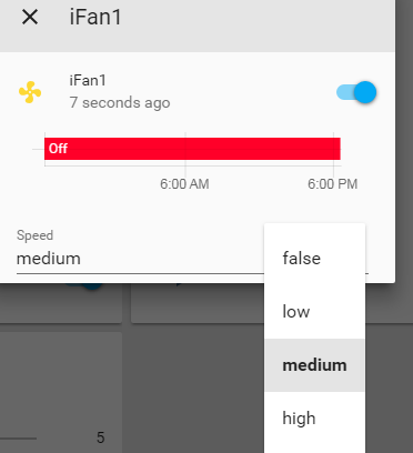
EDIT
Got it fixed as below by eliminating that speed from the list. It was breadcrumb from what you fixed with the templating.
EDIT2
I also found after reviewing some other HA documentation that the reason false shows up is that YAML considers off, 0, and false = false unless you put them in quotes.
jumblies
on 15 Jul 2018
@jumblies
I only have low/medium/high on my speed selection. The switch sets it to 0 as the off state so it's not needed to have a separate off speed
kbickar
on 15 Jul 2018
What are you using for the light ? Im using
light 4:
- platform: mqtt
name: "fan light 1"
command_topic: "cmnd/sonoff_fan1/power1"
state_topic: "stat/sonoff_fan1/POWER1"
qos: 1
payload_on: "ON"
payload_off: "OFF"
retain: true
But if I turn light on with HA dashboard icon it also turns the fan icon on but the fan does not start.
sleezy100
on 15 Jul 2018
@sleezy100 I'm actually using a smart bulb so I don't use that function, but I tested it and see the issue - the state value needs to be changed to:
"{% if value_json.FanSpeed == 0 -%}0{%- elif value_json.FanSpeed > 0 -%}2{%- endif %}"
That prevents it from showing the fan as on when the light message comes in
kbickar
on 15 Jul 2018
My soldering skills are not great. Seems TP 16 is not accessible now due to bad soldering job.
This is how it looks now. Anyway to access it? Seems this one is gone now.

donoo
on 15 Jul 2018
I had the pad lift too. The test points are not robust. I don't know how
exactly they're different from regular pads but mine was buggered exactly
the same way. All is not lost. You can remove the metal cover on the front
of the board and short the trace on the chip itself at boot.
I couldn't find another decent GPIO0 trace, but I'm not an expert. I was
able to serial flash it by holding the button, shorting to the chip and
then flashing. Not easy and I was very relieved when it worked.
On Jul 15, 2018 06:35, "donoo" notifications@github.com wrote:
My soldering skills are not great. Seems TP 16 is not accessible now due
to bad soldering job.This is how it looks now
[image: image]
https://user-images.githubusercontent.com/32016319/42733043-c7b74b8e-8848-11e8-91d5-91259c5b99e1.png—
You are receiving this because you were mentioned.
Reply to this email directly, view it on GitHub
https://github.com/arendst/Sonoff-Tasmota/issues/2839#issuecomment-405082020,
or mute the thread
https://github.com/notifications/unsubscribe-auth/AXFbv39Xs8qXpVNMmZMe8UkWot91D0Faks5uGxr7gaJpZM4UPDk4
.
jumblies
on 15 Jul 2018
@jumblies thanks ! I have ordered UART adapter. It will reach tomorrow. Will try again tomorrow. My pi setup did not work well not sure what i m doing wrong.
donoo
on 15 Jul 2018
@jumblies Sorry to bug you again, can you help me to locate GPIO0 on chip,
here is the pic,
donoo
on 15 Jul 2018
One thing to be sure of on the adapter, check the voltage. I killed my
first sonoff using an adafruit ftdi cable. It has 3.3v level shifting but
for some reason it only supplies 5v. I wasn't aware and while SOME esp8266
are 5v tolerant (not really, they just don't melt right away or have an
onboard regulator) the sonoff most definitely is not.
most ebay and ali boards have a jumper for 3.3 / 5 so it's harder to make a
mistake.
On Jul 15, 2018 07:49, "donoo" notifications@github.com wrote:
@jumblies https://github.com/jumblies thanks ! I have ordered UART
adapter. It will reach tomorrow. Will try again tomorrow. My pi setup did
not work well not sure what i m doing wrong.—
You are receiving this because you were mentioned.
Reply to this email directly, view it on GitHub
https://github.com/arendst/Sonoff-Tasmota/issues/2839#issuecomment-405085769,
or mute the thread
https://github.com/notifications/unsubscribe-auth/AXFbv1Lz-ZLueG5DIK2b7sz3E3RUOPsVks5uGyw5gaJpZM4UPDk4
.
jumblies
on 15 Jul 2018
@kbickar That's sorted it.
Thank you.
sleezy100
on 15 Jul 2018
I have ordered this one, seem it has separate 3v and 5v pins
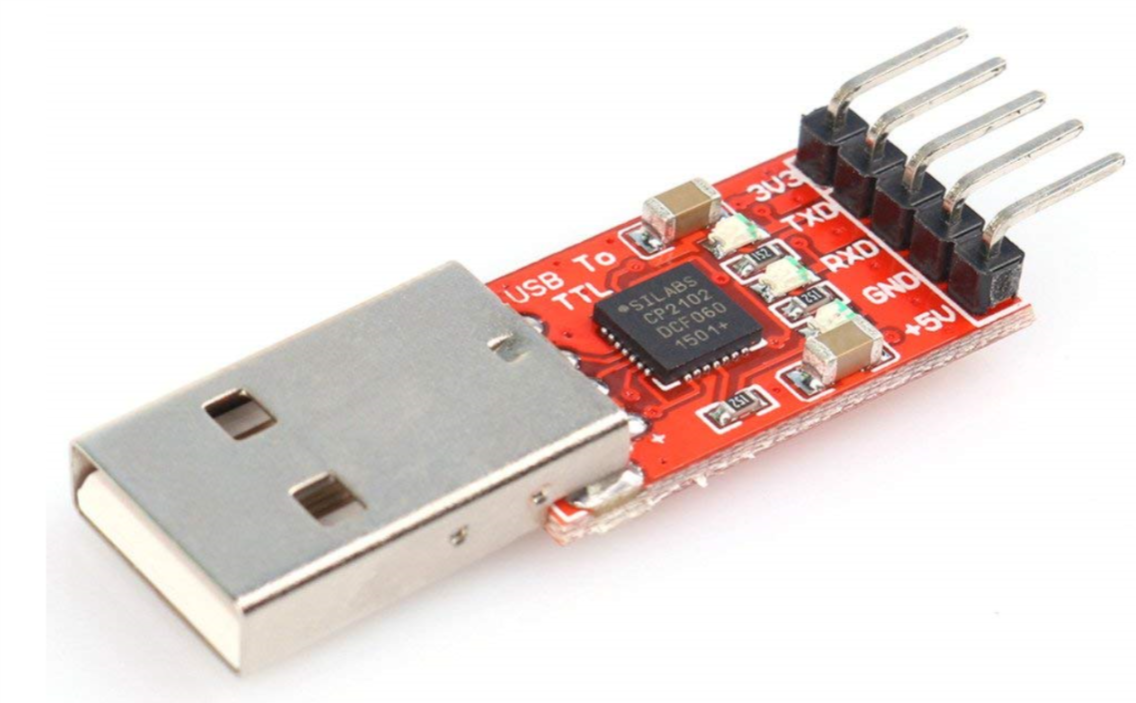
donoo
on 15 Jul 2018
@donoo
That seems like a good choice on the adapter. I've never used that exact type but it should be fine.
I've edited the pic you uploaded and added a pinout image. The dot on the chip is the index and serves to orient you to the chip. The pinout shows the dot and numbering so GPIO0 is kitty corner from the dot, but one in.


Note that to match the pinout, you need to rotate the pic CCW 1/4 turn
I took a few minutes to edit the iFan02 Wiki with our troubles on TP16. I think this isn't a "real" pad and is just a tiny spot of solder paste adherent to the trace.
jumblies
on 15 Jul 2018
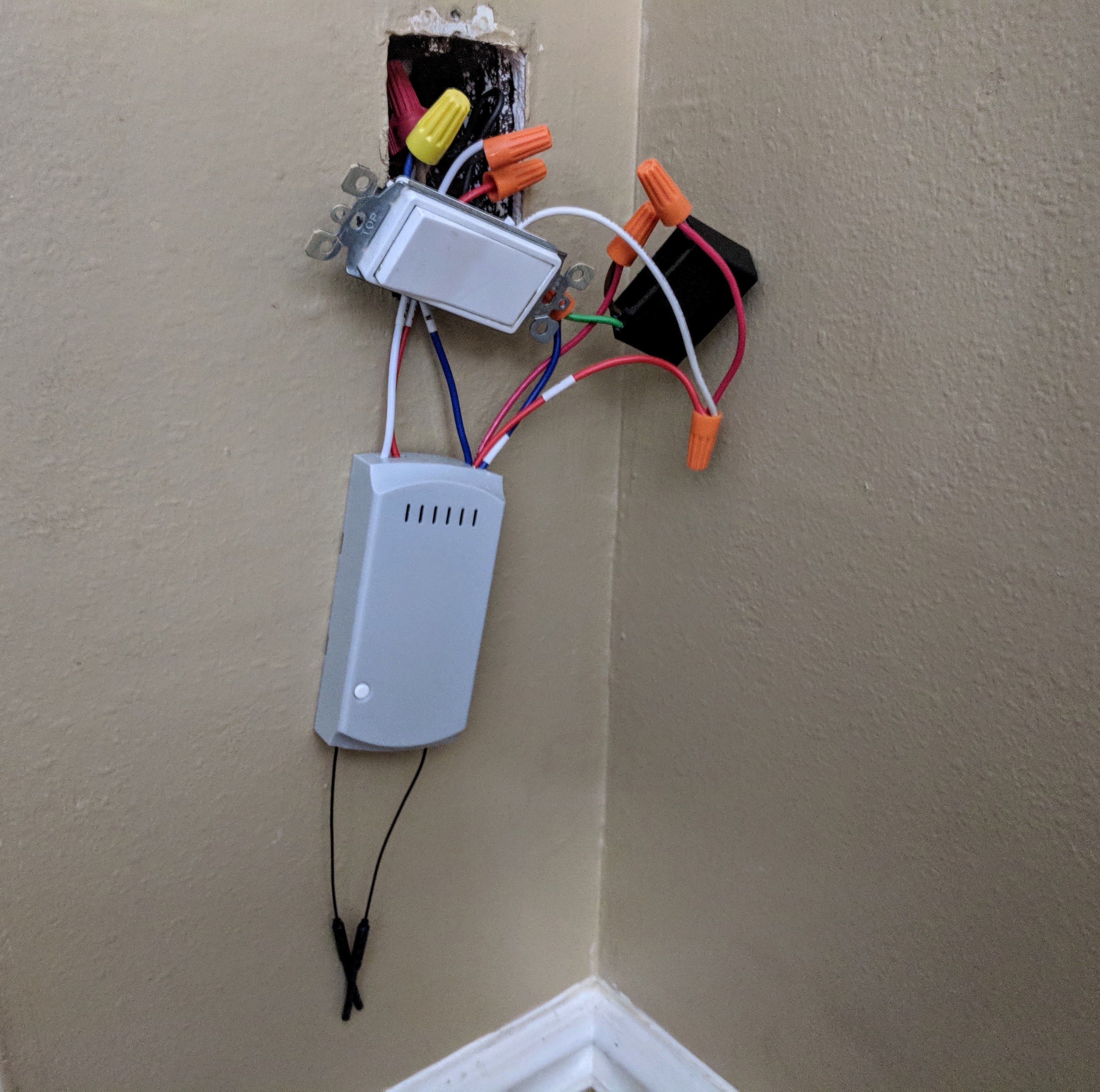
How is everyone mounting this? Now that it is functional, fitting everything in the fan housing is impossible for me anyway. The iFan in the case is just a bit to big to squeeze through the fan mount on the ceiling. I could put in the attic at the junction box, but it's pretty hot up there. If I did that I'd bury it against the drywall under the insulation
Also, have recessed lighting so the light component is perfunctory right now.
options I'm considering
- control recessed lighting with the iFan light leads to sketchy wiring
-- I'd also lose dimming on my recessed cans - add light kit
-- seems silly to add a light kit, but it is inexpensive - add larger sconce/skirt to fan to hide iFan
-- probably necessary regardless - add led strip as shown in image below to top of fan for backlighting.
-- unfortunately, backlighting with LED shows EVERY minor sheetrock flaw. (image below right)
jumblies
on 16 Jul 2018
@jumblies My fan has a big casing that's flush against the ceiling with the motor and wiring, so I was able to put it flat against the bracket connected to the joist above in the top case:
kbickar
on 16 Jul 2018
@jumblies
Finally able to recover ifan2 using serial after bad OTA update using SonOTA using version 6.1.0
Here are my steps:
- Connected UART TX -> RX of Sonoff on J3
- Connected UART RX -> TX of Sonoff on J3
- Connected UART GND -> GND of Sonoff on J3
- GPIO0 of Sonoff -> GND on Sonoff on J2 - - I directly used wire to short chip as shown by @jumblies above. My TP16 was ruined by bad soldering. I think best way is to hold wire against it.
- Press and Hold Button on Sonoff
- Applying AC Power to Sonoff
- Releasing 4 and 5
It should start flashing. I used latest 6.1.1 version.

Huge thanks to @jumblies!!! without your help I don't think I would have recovered this device. One more help required :) Should I put back the metal plate? or it is ok to keep it open. I don't think it is used as thermal sink as it is not touching chip.
donoo
on 16 Jul 2018
Nice job!! I knew it wasn't a forever brick ;)
digiblur
on 16 Jul 2018
Great job! Feels good when something goes right. I doubt the shield is
very important. The antennae are located away and I'm not sure why it's
there
Okay, maybe it should be there.
https://resources.altium.com/pcb-design-blog/pcb-emi-shielding-using-cans
On Jul 16, 2018 15:16, "digiblur" notifications@github.com wrote:
Nice job!! I knew it wasn't a forever brick ;)
—
You are receiving this because you were mentioned.
Reply to this email directly, view it on GitHub
https://github.com/arendst/Sonoff-Tasmota/issues/2839#issuecomment-405351002,
or mute the thread
https://github.com/notifications/unsubscribe-auth/AXFbv8-K2Sm6xPuakFoXgbCD1ohRtBghks5uHOZ2gaJpZM4UPDk4
.
jumblies
on 16 Jul 2018
Anyone have any thoughts on Silence / Silencing / Buzzer / Beep / Tone (extra terms for search availability) It seems that @arendst has already opined that it is a second MCU that controls the buzzer for remote functions (presumably the ARM processor referenced above) that operates in isolation from ESP, so Tasmota has no control on it. Issue #3121
Whenever it drops wifi, it starts screaming, which in my case was due to a midnight router reboot.
For now, mine will be receiving a dollop of silicone to muffle it.
And just a shout out for anyone not aware, the TasmoAdmin is a thing of beauty. I put it on my RPi running DietPi yesterday in about 20 minutes, with none of the usual docker shenanigans. It replaced a crapload of kluges in my HA configuration.
jumblies
on 17 Jul 2018
you do not need to remove the shield, just grounding the GPIO0 from the underside while connecting the Serial interface to laptop.
AS per the Tasmota instructions, NEVER connect the AC power to the sonoff when you connect the serial interface.
If you are not getting enough power from the serial you may need to get a slightly better serial interface that can handle the current draw.
I did get my wife to plug in the USB while I was holding the GPIO0 (TP16) to ground with a jumper wire.
I also soldered header pins for the 3.3, rx, tx and gnd pins for serial, just makes it easier.
 jasonbooker003
on 17 Jul 2018
jasonbooker003
on 17 Jul 2018
@jumblies if you mute on remote, is it still buzzing? I have not connected mine with fan. Also I generally use wificonfig as 5 no restart when no wifi. Does it have any impact on buzzing ? I m planning to configure it on fan this weekend.
donoo
on 17 Jul 2018
@jasonbooker003 i have to remove shield due to TP trace was damaged due to soldering.
donoo
on 17 Jul 2018
@donoo You are right that silencing on the remote seems to have stopped but I also changed the router reboot (it's a second router to a backup WAN connection used for work).
I managed to fit everything under the canopy (the term for the cover at the ceiling mount) . On my cheapo hampton bay fans it was an incredibly tight fit. The iFan02 itself barely squeezes in between the legs of the mount and it's even tighter under the canopy. I had to reroute wires through the downrod becuase there was zero room between the ball mount and the iFan02 Casing. I drilled holes in the downrod near the ball and had them exit to allow clearance. Even still, there is very little freedom for the fan to move in the mount without hitting the plastic case of the iFan02. I can confidently say that any environmental sensor within the canopy would be of little value not mention consuming even more space.
I ended up going with a cheap light kit, which was recommended by the wife and am happy with it.
I have one more to install and I think I'm going to go less janky and look for a larger canopy and integrate a temp sensor or microwave occupancy sensor or both. What I really want is for the fan to come on full blast when I'm heating up on the exercise bike. I don't think the global room temp will be reliable so occupancy with a FanSpeed of 3 after 5 minutes of occupancy is probably the automation I'll use.
I write all this reflecting on the first install which was successful but required problem solving to get it done. These modules are a great value (wifi + remote is unheard of at this price) but not exactly a drop in solution. Removing it for serial flashing would also be a nightmare (refer to problems with current binaries) #3224 . In general, I try not to embed these into infrastructure where they are not accessible and from here on out, I'm building them with a 4 pin JST connector to the 4 vital pins so the case doesn't have to be reopened. Then I can plug the JST into a sensor or serial port.
It seems like a hacker friendly design could be built with these items integrated, but I doubt it could be done at the price iTead is offering.
jumblies
on 20 Jul 2018
@jumblies
I too managed to put this in fan canopy with difficulty. Also I have to re-route light wire to light kit as there were only two wires going inside fan. Have to take down fan and work with it.
Second issue I m facing is my fan canopy is of brass so both WIFI and RF is not working reliably . Exposing black antenna wire looks ugly on white celling. Need to check how I can increase WIFI coverage. Not very happy with current setup, have to tinker bit more to make it work reliably.
donoo
on 21 Jul 2018
I'm living with the antennae for now, but i think the best compromise is
white shrink tubing over them with them sticking out of the canopy. If
they were white I don't think it would look as bad. The antennae are not
much more than wires with heat shrink already.
On Jul 21, 2018 12:24, "donoo" notifications@github.com wrote:
@jumblies https://github.com/jumblies
I too managed to put this in fan canopy with difficulty. Also I have to
re-route light wire to light kit as there were only two wires going inside
fan. Have to take down fan and work with it.
Second issue I m facing is my fan canopy is of brass so both WIFI and RF is
not working reliably . Exposing black antenna wire looks ugly on white
celling. Need to check how I can increase WIFI coverage. Not very happy
with current setup, have to tinker bit more to make it work reliably.
—
You are receiving this because you were mentioned.
Reply to this email directly, view it on GitHub
https://github.com/arendst/Sonoff-Tasmota/issues/2839#issuecomment-406807669,
or mute the thread
https://github.com/notifications/unsubscribe-auth/AXFbv7k22WifnVAx61xGFb_FjgJZRyh2ks5uI1WrgaJpZM4UPDk4
.
jumblies
on 21 Jul 2018
Looking at the size on the site it compares to about the size of a Sonoff dual. I have put those in 3 gang boxes before. Actually smaller than I thought now and definitely changes some ideas for me. Probably still put them in the junction box as I don't want to have to fish wires back from the canopy for the buttons.
digiblur
on 21 Jul 2018
@digiblur re: fishing
Oh heck no! that would suck. better to mount the remote on the wall, which it seems to be designed for since it has bung-hole in the bottom half, presumably for a mount.
jumblies
on 21 Jul 2018
I have two more fans with light kit and canopy is of brass. I m thinking to route light kit wire up to fan switch on wall. Then fit the controller inside of wall switch. I have already done similar thing with Sonoff Dual. This will solve problem of WIFI coverage issue and I have easy access to controller too. Will try this next week. It is bit of a hassle but seems better then my current setup... in theory :)
donoo
on 21 Jul 2018
Is anyone facing restart issue? Sometime when fan light is on and i try turn on fan, ifan02 restarts. I have 3 LED bulbs of 2.5 watt in light kit.
donoo
on 22 Jul 2018
The only unexpected restarts I've seen involved router reboots / wifi drops. Not sure if it's built into the firmware but rather than connecting to the secondary AP, the sonoff reboots.
@donoo given your signal strength issue above, I'd suspect something similar. The power draw form LED bulbs is probably not sufficient to induce a reset. If you have an old router, you can put it in AP
or repeater mode in the same room for troubleshooting.
Else you could log both the reset cause and / or signal strength since they are given in telemetry and status json messages. This presumes your MQTT broker / server or whatever they call it now is connected to something with a logging facility.
The other potential cause which I often prophylactically treat though I have not seen it remedy anything is to clear retained messages from the broker b/c a retained restart 1 message can induce unexpected reboots, but it would seem to me that this would be a bootloop type pattern rather than sporadic.
I use a shell script to delete the mosquitto database for this on my bare metal install but am transitioning to docker and in that I can just restart the container as I don't have it implemented with persistent volumes. Deleting retained messages is a PITA when you try it on a topic level. Maybe someone has a recursive method.
jumblies
on 22 Jul 2018
@jumblies i was observing it closely, it happens when fan light is on and if then i try to turn on fan, controller restarts. I can also see drop in light on leds for a fraction of second and then whole system restarts. Messages on console says restarting due to external system something. I don't remember exact message.
I think it is not able to keep up with the fan load when lights are on.
One more thing in my setup is, I have another speed controller on wall too. I have kept this one on full speed. Not sure if this is creating problem. I m going to remove this speed controller to see if this has any effect. If it is not working properly I will drop to put this on other two fans. They have 4 bulb light kits.
For your reboots issues, you can set WifiConfig to 5, this will not reboot the systems if there is WIFI drop.
donoo
on 22 Jul 2018
well, at least you have some variables to suss out. That's a good start.
On Sun, Jul 22, 2018 at 11:51 AM, donoo notifications@github.com wrote:
@jumblies https://github.com/jumblies i was observing it closely, it
happens when fan light is on and if then i try to turn on fan, controller
restarts. I can also see drop in light on leds for a fraction of second and
then whole system restarts. Messages on console says restarting due to
external system something. I don't remember exact message.I think it is not able to keep up with the fan load when lights are on.
One more thing in my setup is, I have another speed controller on wall
too. I have kept this one on full speed. Not sure if this is creating
problem.—
You are receiving this because you were mentioned.
Reply to this email directly, view it on GitHub
https://github.com/arendst/Sonoff-Tasmota/issues/2839#issuecomment-406876736,
or mute the thread
https://github.com/notifications/unsubscribe-auth/AXFbvxIOywl_tLl4NHTSlYIJ7o4cvanvks5uJJ-CgaJpZM4UPDk4
.
--
“The best way to predict the future is to design it.” —Buckminster Fuller
jumblies
on 22 Jul 2018
I came up with a separate power supply that had significantly more output current (1.58A @ 19VDC) and hacked it into the serial comm connections. I posted this on a different issue since I thought this one was closed (since it says so at the top).
So far I've managed to connect this up to a sonoff basic I had laying around and it can power it and I can see the comms on the ArduinoIDE so it's working and no smoke. And I don't have to mess with main AC power to power the module during flashing.
I guess I still need to test it on the iFan02 but I don't see why it wouldn't work.
If it's working properly and I connect everything up without putting it in flash mode what should I see on the serial interface and physically on the iFan02 module?
finity69x2
on 22 Jul 2018
@finity69x2 Thanks for posting. If you can reference the other issue that would be great. If anyone tests this and it works, hollar at me and I'll wiki it.
jumblies
on 22 Jul 2018
issue #3292. And will do. Hopefully I'll be testing it myself soon.
finity69x2
on 22 Jul 2018
@jumblies
I just tested my set up and it worked like a charm.
I made a small modification to the above drawing. I used a 2.4A @ 5V wall-wart style USB power supply instead of the 19V PS. But other than that its exactly as shown above.
I can modify the drawing if you want but no matter what the input voltage is the basic principle of operation will be the same.
I can put some part numbers on the drawing to "info" it up a little, too, if that would be helpful.
Just let me know what you need and I'll get it together.
No more rubber underwear! Yay!
finity69x2
on 24 Jul 2018
One thing I can't figure out is how to pair the remote to the controller? Any hints or am I just over looking something really easy?
finity69x2
on 24 Jul 2018

Here is what I'm going to post in the wiki in lieu of rubber underwear suppliers.
jumblies
on 24 Jul 2018
perfect. works for me.
the only other thing I may add to it that I didn't mention before is that I soldered a wire to the ground pin on the buck converter so that I can touch the other end of the wire to TP16. So no need to solder anything to that TP on the iFan02. Then I plug everything in, hold down the button, touch the jumper onto TP16 then I use a voice controlled sonoff to turn on power to the usb power supply. :)
finity69x2
on 24 Jul 2018
I got my two units in and I was able to flash them using the OTA method luckily so rubber underpants thing for me. I would like to circle back to the capacitor sizes again. It looks like I'm in the same boat as a few others. I've tried it on two fans just to see how it performs. The fan pull string was left on full speed during the test, I get the same as mentioned, 3 on iFan02=Same as before, 2= is the old 1 one speed, and 1 is just so slow that we wouldn't use it like that. We typically use fan speeds 2 or 3 so losing 2 is a huge issue to us.
I think mine are the typical harbor breeze fans you get at Lowe's, I haven't pulled the capacitor on the fan it self to see the size, I wouldn't be past picking up a few of the same capacitors but different sizes and swapping them out. Anyone done this yet?
digiblur
on 25 Jul 2018
You can look up the caps on the image above. That's a standard harbor
breeze budget fan cap. I think to replicate the factory speeds, you'd
need to desolder the on board caps and replace it with the factory unit, at
least that's what my combinatorial experiment showed.
I think itead just selected some generic sizes of the caps. Not sure what
market those would work for, maybe none, which is said to be the optimal
compromise (nobody wins! yay).
Having used mine for a little over a week, I don't miss the other speed.
Speed 1 is useless but 2 and 3 are fine and more than adequate for me.
Personally, I hated pulling the chain repeatedly to figure out what speed I
was on and having both wifi and remote control adds all the value I need.
On Wed, Jul 25, 2018 at 4:19 PM, digiblur notifications@github.com wrote:
I got my two units in and I was able to flash them using the OTA method
luckily so rubber underpants thing for me. I would like to circle back to
the capacitor sizes again. It looks like I'm in the same boat as a few
others. I've tried it on two fans just to see how it performs. The fan pull
string was left on full speed during the test, I get the same as mentioned,
3 on iFan02=Same as before, 2= is the old 1 one speed, and 1 is just so
slow that we wouldn't use it like that. We typically use fan speeds 2 or 3
so losing 2 is a huge issue to us.I think mine are the typical harbor breeze fans you get at Lowe's, I
haven't pulled the capacitor on the fan it self to see the size, I wouldn't
be past picking up a few of the same capacitors but different sizes and
swapping them out. Anyone done this yet?—
You are receiving this because you were mentioned.
Reply to this email directly, view it on GitHub
https://github.com/arendst/Sonoff-Tasmota/issues/2839#issuecomment-407881957,
or mute the thread
https://github.com/notifications/unsubscribe-auth/AXFbv18uxqH469MbHapvGR5Dz5NV-XPIks5uKNLEgaJpZM4UPDk4
.
--
“The best way to predict the future is to design it.” —Buckminster Fuller
jumblies
on 25 Jul 2018
thanks @jumblies,
I could have swore I tried to pair the remote like it said in the instructions but it didn't work. Then when I tried it again now it worked.
@digiblur
Since there is a concern with the fan speeds what I plan on doing is using the sonoff to just transfer MQTT messages back & forth to Home Assistant and then use those signals to control my existing RF fan controller that is working thru the broadlink component. That way I use the new sonoff remote and the existing controller so there's no easy way for the state of the fan to be out of sync with the status in HA. The sonoff will just be ghost switch module with the outputs connected to nothing.
And if all else fails I can easily just grab the old remote out of its hiding hole and I'm back in operation.
finity69x2
on 26 Jul 2018
I ordered some 5uF caps off ebay of similar size. I will report back if it fixes the speed issues.
 mercenaryballs
on 27 Jul 2018
mercenaryballs
on 27 Jul 2018
Does anyone have the dimensions of the caps as well as the distance for the pins so we can find a drop in replacement for US fans?
roofuskit
on 31 Jul 2018
26mm pin spacing on the caps. dimensions of caps 30mm L x 20mm W x 15mm H
mercenaryballs
on 1 Aug 2018
Now who's the electrical engineer gurus who can tell us what size to replace them with?
digiblur
on 1 Aug 2018
PowerOnState setting seems not working on ifan02. Whenever power is applied fan light turns on.
Any other setting I need to configure to change the behaviour.
donoo
on 1 Aug 2018
@digiblur I believe the exact value depends on the fan, but in my research for a 120V fan it should be 4-6uF.
mercenaryballs
on 1 Aug 2018
@mercenaryballs I'll have to pull the one on my fan try to pin it out to see what is what. Only confusion I have I to figure out is based on what gets switched in since now there are two sets of capacitors in play right? If I leave the fan on high itself, that's one capacitor which is fine when the iFan02 is in speed 3, but then when ifan02 speed 1 or 2 is used it kicks in its own capacitor combined with the one the fan itself has for high speed?
digiblur
on 1 Aug 2018
@digiblur I believe the full speed is usually no capacitor, which is how the ifan02 works and why the full speed is the one that remains unchanged for people.
roofuskit
on 1 Aug 2018
@roofuskit right. That's what I said. The schematics show it is a pass through.
digiblur
on 1 Aug 2018
My old ceiling fan controller has 5uF and 6uF caps. Given the medium setting on the iFan02 is just a bit slower than my original speed controller, and medium in the iFan02 puts the two caps in parallel for 5.5uF, I'm guessing my fan's original slow was 6uF. Medium would have been 11uF (paralleled caps).
I tried poking around Digikey and Mouser but was unable to find any suitable parts of the right size. I also emailed Foshan shunde CG Electronic Industry Co., LTD. (manufacturer of the caps in the iFan02) but haven't gotten any reply (not surprising).
Our best bet may be to remove the stock iFan02 caps and solder the wires from a standard potted ceiling fan capacitor onto the PCB. Cut a small notch in the casing to let the wires pass through and it'll just kind of dangle off the side of the iFan02.
 ExplodingLemur
on 1 Aug 2018
ExplodingLemur
on 1 Aug 2018
I was digging around Aliexpress and found a few caps of the same dimension but different values but of course I have my doubts on things and wasn't sure if I wanted to wait that long to find the cap is a bit different. I think your idea is excellent, cheap, quick and I know it will work. I have mine going in a 3 gang box with loads of room already so it would be simple to do.
digiblur
on 1 Aug 2018
@mercenaryballs I was pulled my fan (Hunter brand) and saw it had 2 separate capacitors units(see pics). I didn't map it out to see how things were wired but it looked like the box with 2 capacitors went to the 3 speed pull switch and the other single was further up the line.
According to things I've found this separate capacitor is start cap and the other two are the speeds. I'm familiar with soldering and stuff just the fan capacitor engineering stuff is not my thing...yet.
Could I just get two 5uF capacitors to replace the ones in the iFan02? or of course solder the leads of this capacitor to the iFan02 for the low and high speeds?
digiblur
on 4 Aug 2018
Restart issue i was facing was due to extra speed controller on wall. After removing it everything works fine.
Only issue I have now is if ac power is cut and applied again fan light turns on. I m not able to change this using poweronstate setting. In my place power cuts are frequent.
Anyone have any solution for this problem.
donoo
on 4 Aug 2018
@donoo You are probably better off starting a new issue and others will see it and help out as it could be many things from MQTT settings, home automation gear settings, Tasmota settings, etc, or combinations of many things.
digiblur
on 4 Aug 2018
@digiblur Do you have links to the caps you found on Aliexpress? What search terms did you use?
Hm, I did just find these and these 5uF caps that look to be the right dimensions.
ExplodingLemur
on 5 Aug 2018
@ExplodingLemur Looks like you found some of the same... I have four in my cart saved. The dimensions/info on them made me hold off combined with wanting to test some things first. I pulled the caps that are too small for my fan with 5uf+5uf and soldered some jumpers to them to come out of the ifan02 case bottom. I got rid of the Neutral out that wasn't needed so it was only one additional wire going out. I'll wire the capacitor on the outside. I have another module to do on another fan but I haven't pulled the cover yet to see its capacitor size yet, I would like to do internal capacitors with it though.
digiblur
on 5 Aug 2018
I just ordered two sets of 5uF caps (these and these) and will report back on how well they work when they arrive.
ExplodingLemur
on 7 Aug 2018
Pulled the 5uF+5uF capacitor out of the fan, had to pull the 4 position switch as well since it was all connected. Bypassed it and of course the fan was stuck on full speed. Wired in the capacitor on the two spots where the capacitors used to be on the iFan02. Works perfect! Proof of concept down, throw in the 3 gang and wire up the two push buttons. Need to pull the 2nd fan I'm doing and see the capacitor in it. If it is all good I'll just order some capacitors like you did and put them back on the board.
digiblur
on 7 Aug 2018
I highly recommend Wago lever nuts. They're so much nicer than traditional wire nuts.
ExplodingLemur
on 7 Aug 2018
Yep. I do use them where I have limited space. Due to their cost I don't use them on test rigs. This one won't have as many junctions when it actually goes in its permanent box.
digiblur
on 7 Aug 2018
Would it be possible to replace the relay for the light with a DPDT relay to reverse the fan direction?
 sburlappp
on 8 Aug 2018
sburlappp
on 8 Aug 2018
Has anyone here had the issue where the remote stops responding? I've installed my iFan 02 for 24 hours and the remote has completely stopped responding.
 legotheboss
on 9 Aug 2018
legotheboss
on 9 Aug 2018
@legotheboss yes: https://github.com/arendst/Sonoff-Tasmota/issues/3395
ExplodingLemur
on 9 Aug 2018
Hi all,
I've ordered and installed IFAN02 with Tasmota firmware in one of my none smart ceiling fans and it's working great from Home Assistant and the RF remote.
Now I would like to order another one but i didn't saw an option to change the RF frequency of the remote or fan module.
So my question is:
Is there a way to change the RF frequency?
If not, it means when I press a button on the remote it will trigger both fans?
Thanks.
 tomerbs
on 16 Aug 2018
tomerbs
on 16 Aug 2018
The remote is encoded and is paired with device. It won't turn both on. I
have two and confirmed
On Aug 16, 2018 15:18, "tomerbs" notifications@github.com wrote:
Hi all,
I've ordered and installed IFAN02 with Tasmota firmware in one of my none
smart ceiling fans and it's working great from Home Assistant and the RF
remote.
Now I would like to order another one but i didn't saw an option to change
the RF frequency of the remote or fan module.
So my question is:
Is there a way to change the RF frequency?
If not, it means when I press a button on the remote it will trigger both
fans?Thanks.
—
You are receiving this because you were mentioned.
Reply to this email directly, view it on GitHub
https://github.com/arendst/Sonoff-Tasmota/issues/2839#issuecomment-413655589,
or mute the thread
https://github.com/notifications/unsubscribe-auth/AXFbv35dhHI-FPMRxobwCtfxWOsxrpAYks5uRcV8gaJpZM4UPDk4
.
jumblies
on 16 Aug 2018
Thanks jumblies,
One last question,
do you know if there is a possibility to pair the fan module with different RF remote (not sonoff)?
If its possible i would appreciate if you can please direct me to a guide or manual?
Thanks.
tomerbs
on 16 Aug 2018
I replaced the capacitors. This potted ceiling fan capacitor didn't fit in the case so I cut a small hole for the wires. It works! It's a REALLY tight fit for the capacitor with he fan I have though.
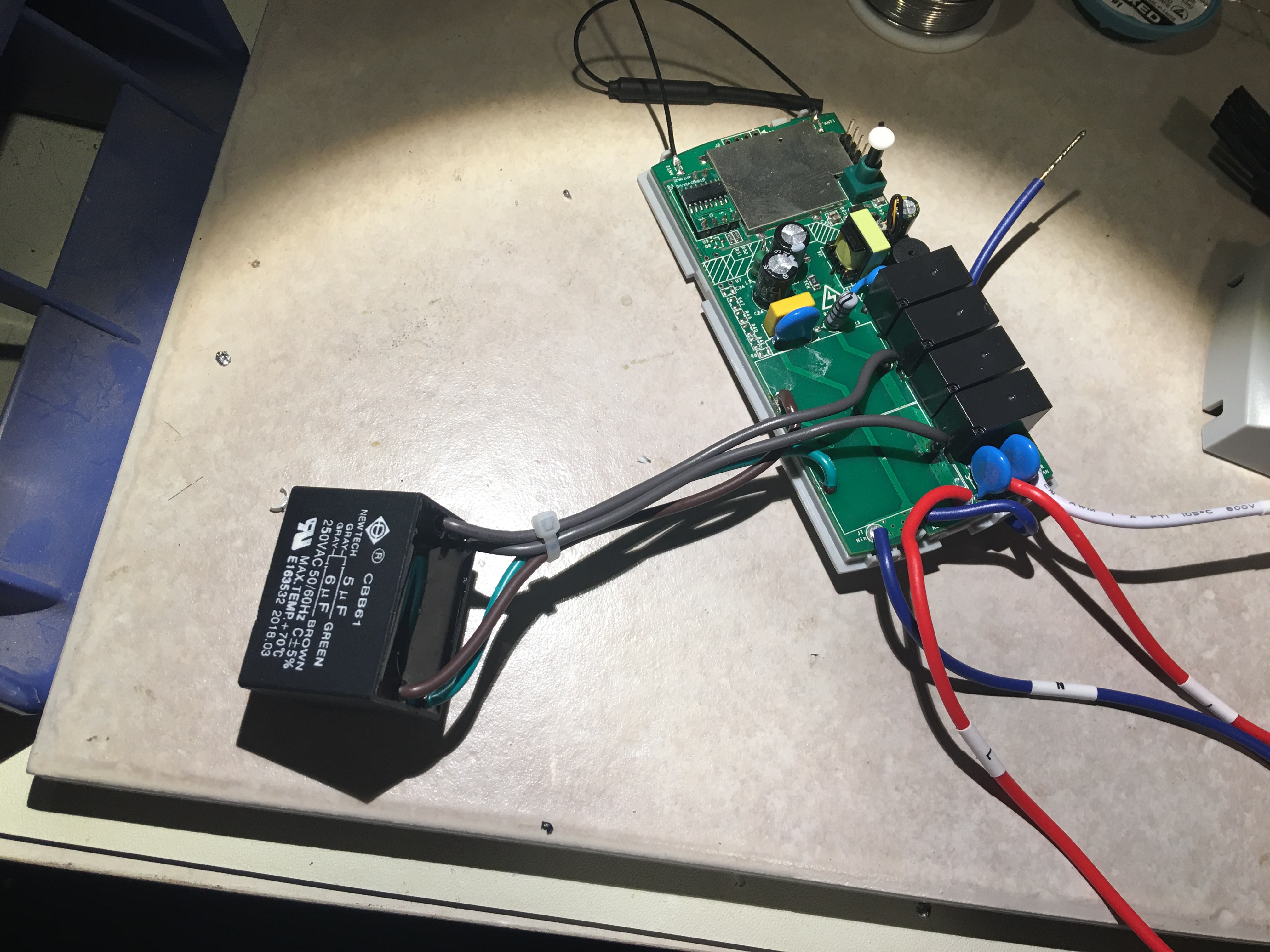
ExplodingLemur
on 19 Aug 2018
Yesterday I installed some 5uf capacitors from eBay. While the shape was the same, they turned out to be a little larger than the original ones and therefore wouldn't work as drop-in replacements. I added somewhat lengthy wires so I could place them in a more convenient area inside the base of the fan. Everything worked great and now the fan speeds are back to normal 😄😄
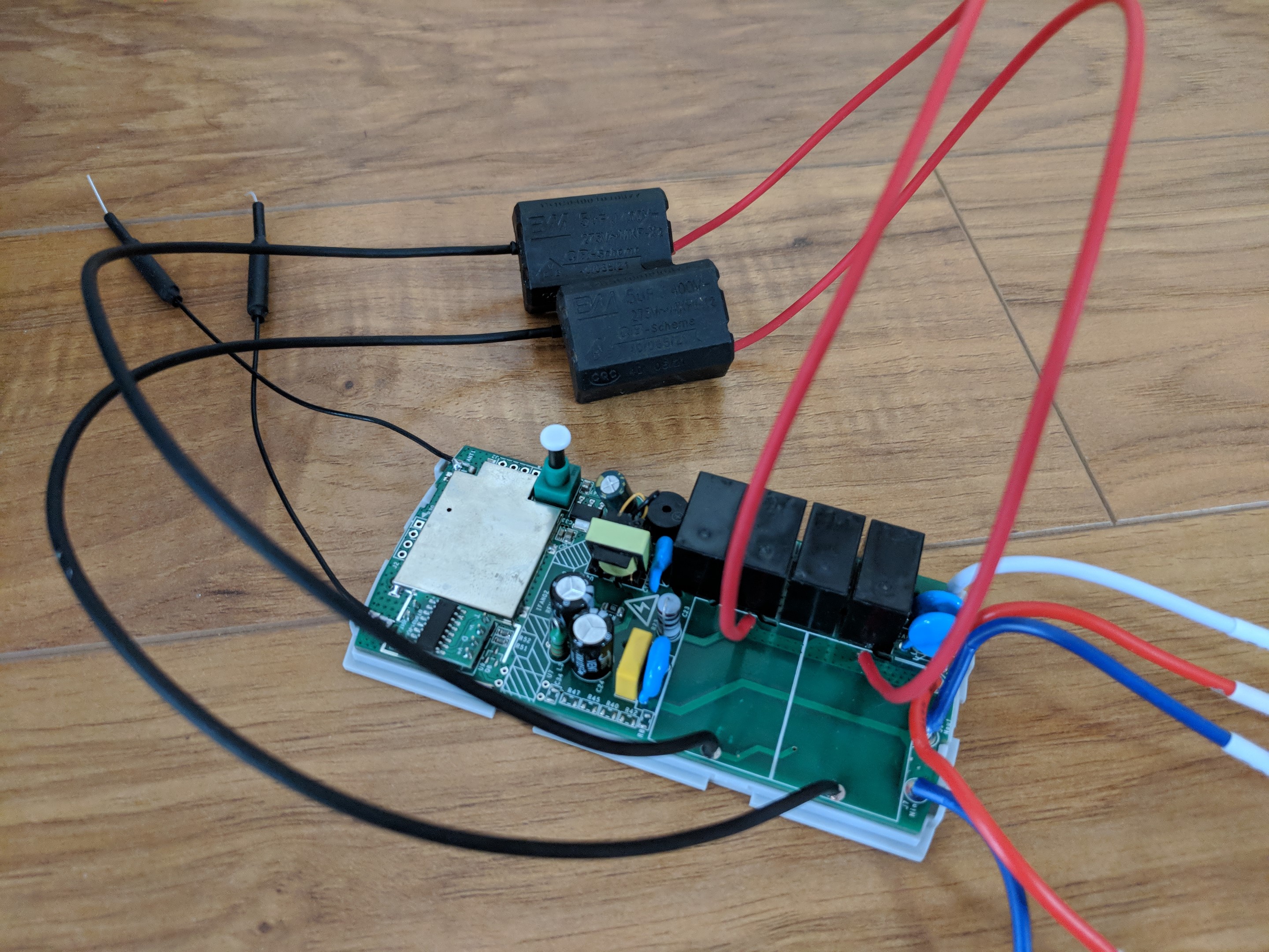
 mjoshd
on 19 Aug 2018
mjoshd
on 19 Aug 2018
@mjoshd @ExplodingLemur
Nice work!
Since the case is kind of hacked and since you're heavily modifying the components, would you consider putting a thermal fuse in? I don't know what type of fuse is used in them. I use this crowdsoured design in my nonsonoff esp projects. PSU
There has been some discussion on the ugly antennae and I think some simple white shrink wrap would make them less obtrusive = ↑ WAF
Another question that's been lingering in my mind is a best practice for mounting. I had one that would start beeping every time my router rebooted so I put some silicone on the buzzer. But it is a huge PITA to take these things out and put them back in when stuffing in the canopy. As I look at them, I think it might be better to mount them alongside the canopy with a notch in the canopy for the wires. The case isn't overly ugly (in factory state). The wires are all on one end. This would also allow a sensor to be attached (been running a BME280 on one of mine). They canopy got warm but not hot when everything was stuffed in it. Obviously this won't work for the hacked capicitor mod.
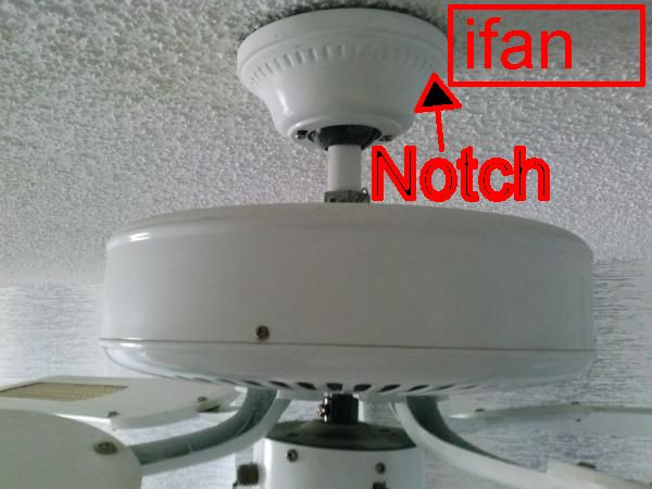
jumblies
on 19 Aug 2018
@jumblies these don't have fuses in them at all :/ At least not on the mains input side. That's something sorely lacking IMO. Take a look at https://github.com/aderusha/HASwitchPlate it uses https://www.digikey.com/product-detail/en/mean-well-usa-inc/IRM-03-5/1866-3020-ND/7704640 for power.
I have the antennas stuffed inside the fan canopy as well so their color isn't an issue for me. No problems with signal strength.
I personally wouldn't mount these with the wires exposed outside a junction box or the fan canopy.
ExplodingLemur
on 19 Aug 2018
@ExplodingLemur
If you guys wouldn't mind dropping specs of the caps you used and what did and didn't work (sizing) in the wiki it would be great.
Agree on the safety of sonoffs. I use a similar appearing Hi-Link which is discussed in the referenced link. The problem is getting fakes which are abundant on Ali. I"ve gotten many fakes from the 3.3/5/12V models and always gotten refunds when complaining about fakes.
I do use the thermal fuse which is also missing from the meanwell (couldn't find it on the datasheet). The above linked PSU ends up with a glass fuse, thermal fuse and a varistor, which appears to cover all bases according to the linked thread (within reasonable design). There are reports of failure of sonoffs (TH16s IIRC) with melting so a thermal fuse seems like a significant safety omission.
I also agree with you about not wanting to stick the iFan02 outside the canopy, but it is a pretty big pain point to get the ladder, climb up and remove it with attendant breaker shutdown and startup. Also there is the consideration of the recent corrupted binary uploaded to github and propagated through the tasmota upload facitlity that led to a lot of folks having to yank their in wall buried units and serially reflash them before it was replicated and fixed. Just data points. I do like them inside the canopy but fitting them there is tight for my budget fans and replacing the canopy is not pragmatic b/c of sizing of the mount.
jumblies
on 19 Aug 2018
I just got 4 of these and put Tasmota on the first one. Here's a few observations/requests:
- I couldn't make an external power supply work. I tried several and ended up flashing Tasmota with mains power.
- When flashing, it would only stay in flash mode for a fixed period of time. I was trying to upload with PlatformIO and it wasn't working so I went to ESPTool. It made it to 25% and quit. On the next try, because I got the command entered faster, it made it to 35%. So I had everything ready to go "esptool.py --COM..." and as soon as I powered up and disconnected GPIO00 I hit enter on the esptool command and it was able to finish flashing.
- That buzzer is ridiculous. Console command ledstate 0 takes care of it, right?
- Do you recommend disabling serial logging on this one (like the 4ch)?
- I built on arduino 2.4.2 and used user_config_override to set my project name, which worked. But the MQTT topic, as defined in user_config.h as: #define MQTT_TOPIC PROJECT , did not work. The topic came up as "sonoff". No big deal. Simple change in console.
 welbo97
on 22 Aug 2018
welbo97
on 22 Aug 2018
I couldn't make an external power supply work. I tried several and ended up flashing Tasmota with mains power.
Did you join your serial adapter ground to the power supply ground? How much current were your power supplies capable of sourcing?
That buzzer is ridiculous. Who in their right mind thought that would be a good idea? Can we disable it with a console command or is silicon or unsoldering the only solution we have right now?
Per the schematic it's hanging off of the secondary microcontroller which handles switching and sequencing the relays. The ESP8285 has no direct control over it. When you hit the mute button on the RF remote, that command goes straight to the secondary micro. For now the only way is to remove it or attenuate it with silicone or hot glue.
ExplodingLemur
on 22 Aug 2018
@welbo97 What serial device did you use? None of my FTDIs could power the iFan02, but a CH340G paired with a lm1117 3.3v regulator was able to flash the whole setup perfectly fine. Another trick was to use a Raspberry Pi 3.3v bus and use a common ground.
legotheboss
on 22 Aug 2018
I used OTA flash and it worked perfectly. I however didn't have much luck with capacitive buttons on the GPIO pins. One wouldn't even let it boot while being held low. I don't remember off hand if it was RX or TX. However i2c works just fine!
digiblur
on 22 Aug 2018
@ExplodingLemur
Using the "ledstate 0" silences a majority of the beeps. The mute button has taken care of the rest I think. I might still put some hot glue on it just to make sure.
@legotheboss
My serial adapter is a FTDI knock-off (CP2102). I didn't even try to power it with that. When I first got into this (a few weeks ago), I had a lot of problems powering my sonoff basic's with the raspberry pi as it would often reboot the pi when I connected the esp 3.3V. I have an arduino mega that also wouldn't power the iFan02. So I tapped into the 3.3V output of a sonoff basic and tried that. The measured voltage at the input to the iFan02 was 3.28V pretty steady. The best I was able to get was a few recognizable letters when I connected power ("bootmode (3,7)") with the serial interface lowered to 74,880 baud. Going back to mains power, I had full speed and a good solid connection.
The 3.3V connection ground went into the power bus line of a breadboard, along with the FTDI ground and the iFan02 ground. The 3.3V positive went into the other power bus line of the breadboard and then to the iFan02. It looked just like the diagram above, using the 3.3V buck regulator.
There's three more to program so I'll play a little more and see if anything turns up different.
@digiblur
I haven't used OTA flash before. Every time I get started reading up, I see the warning that it doesn't work with sonoff firmware greater than 1.6. Are you using a different OTA tool than the one linked in this wiki?
welbo97
on 22 Aug 2018
@welbo97 nice tip on the Ledstate! Although now that I think of it my bins have my led state default to MQTT messages. Wonder if that's why I kept hearing a damn beep with a button on TX or RX!
You can use it on devices with firmware 2.0 or above now. I was skeptical about it at first but it was pretty easy. I figured if it failed I would just go the usb adapter route but it flashed just fine. Other devices that have easy GPIO pin access I will just go that route though.
digiblur
on 22 Aug 2018
Since this thread seems to be the catch all, does anyone have a copy of the original sonoff firmware?
My remote has "unpaired" itself from the unit and with tasmota, it seems there is no way to re-pair it, at least in my case. I can't get the iFan02 to enter the pairing mode and I suspect tasmota is intercepting the the buttonpress which was forwarded on factory FW. If any of you have experience re-pairing with tasmota, I'd love to hear. It could be that my daughterboard or remote or both have quit.
jumblies
on 24 Aug 2018
@jumblies
I wondered the same thing about re-pairing after tasmota flash. Maybe it needs a new issue.
I still have a couple of iFan’s I haven’t flashed. I’ll download the original .bin for you. It’ll be later tonight though. I can put it into one of my repo’s? Unless you have a better way to send it.
welbo97
on 24 Aug 2018
Just as an FYI for anyone who is using the stickied Home Assistant configuration from the wiki and are getting any strange errors:
I've been playing around with the code and (with a little assistance from the HA forum) I came up with a working Home Assistant configuration:
- platform: mqtt
    name: "Master Bedroom Fan"
    command_topic: "cmnd/sonoff_MBR_fan/FanSpeed"
    speed_command_topic: "cmnd/sonoff_MBR_fan/FanSpeed"
    state_topic: "stat/sonoff_MBR_fan/RESULT"
    speed_state_topic: "stat/sonoff_MBR_fan/RESULT"
    #state_value_template: "{% if value_json.FanSpeed == 0 -%}0{%- elif value_json.FanSpeed > 0 -%}4{%- endif %}"
    state_value_template: >
      {% if value_json.FanSpeed is defined %}
        {% if value_json.FanSpeed == 0 -%}0{%- elif value_json.FanSpeed > 0 -%}4{%- endif %}
      {% else %}
        {% if states.fan.master_bedroom_fan.state == 'off' -%}0{%- elif states.fan.master_bedroom_fan.state == 'on' -%}4{%- endif %}
      {% endif %}
    speed_value_template: "{{ value_json.FanSpeed }}"
    availability_topic: tele/sonoff_MBR_fan/LWT
    payload_off: "0"
    payload_on: "4"
    payload_low_speed: "1"
    payload_medium_speed: "2"
    payload_high_speed: "3"
    payload_available: Online
    payload_not_available: Offline
    speeds:
      - off
      - low
      - medium
      - high
@welbo97
I have used the set up I wrote up above a few times and I haven't had any issues with it working.
@tomerbs
While you can't (yet...) pair the remote to a different controller what you CAN do is set up your automations to use the MQTT messages generated by the controller to control both fans via each remote.
For example, use the state topic from one controller (that gets turned on by it's remote) to send the command topic to the other controller. I haven't thought specifically how that would work to not get into an infinite feedback loop of MQTT messages between the two fans but I think it should be possible.
finity69x2
on 24 Aug 2018
@welbo97 make sure you don't have any passwords saved in the ifan02 when you dump the firmware. Didn't want to assume you knew this, so ignore this if not needed.
digiblur
on 24 Aug 2018
I don't think the pairing has anything to do with the firmware installed on the device. I actually paired my remote to the controller after I flashed Tasmota onto it and it worked fine.
finity69x2
on 24 Aug 2018
@finity69x2 what errors did you have? Definitely update the wiki if it improves things. Thanks for the work you did on the template and sharing it with us.
digiblur
on 24 Aug 2018
Every time I changed the state of the light I was getting an error for the state of the fan that "value_json.FanSpeed" didn't exist.
It was caused by the MQTT topic "stat/sonoff_MBR_fan/RESULT" returning { "POWER1":ON } when the light was switched while at the same time the value template for the fan state was looking for {"FanSpeed":
It didn't really cause any operational issues but just put an annoying entry in the log.
The code above eliminates that error.
finity69x2
on 24 Aug 2018
A repo would be great. Much appreciated. I opened an issue and Theo
responded but we can't think of a workaround. The only other way that
occurs to me would require reverse engineering the pairing command to the
daughter board by signal analysis... And ain't nobody got time for dat!
I think the original fw interprets that long press and triggers a signal to
the daughter board that puts it in pairing mode. BTW, based on frequency
and board markings, I think it's using Bluetooth.
On Aug 24, 2018 12:22, "welbo97" notifications@github.com wrote:
@jumblies https://github.com/jumblies
I wondered the same thing about re-pairing after tasmota flash. Maybe it
needs a new issue.
I still have a couple of iFan’s I haven’t flashed. I’ll download the
original .bin for you. It’ll be later tonight though. I can put it into one
of my repo’s? Unless you have a better way to send it.
—
You are receiving this because you were mentioned.
Reply to this email directly, view it on GitHub
https://github.com/arendst/Sonoff-Tasmota/issues/2839#issuecomment-415809801,
or mute the thread
https://github.com/notifications/unsubscribe-auth/AXFbv1hcN3vB7DGY6b_I6EfJKTrBOkrQks5uUChBgaJpZM4UPDk4
.
jumblies
on 24 Aug 2018
That's a good data point. I'll try factory fw and see if it helps. I
haven't ruled out a bad remote and / or daughter board. Does your unit
enter pairing mode with a long press? Mine just acts like a switch, no
matter how long I hold it.
On Aug 24, 2018 12:27, "finity69x2" notifications@github.com wrote:
I don't think the pairing has anything to do with the firmware installed
on the device. I actually paired my remote to the controller after I
flashed Tasmota onto it and it worked fine.—
You are receiving this because you were mentioned.
Reply to this email directly, view it on GitHub
https://github.com/arendst/Sonoff-Tasmota/issues/2839#issuecomment-415811064,
or mute the thread
https://github.com/notifications/unsubscribe-auth/AXFbv0YT89L3Sdk6vxhIkmsCt7TEmQe2ks5uUClZgaJpZM4UPDk4
.
jumblies
on 24 Aug 2018
@jumblies No worries. I’ll get it posted in there tonight.
@digiblur I’m just pulling the virgin firmware so there shouldn’t be any passwords that I can think of. Let me know if I missed something.
@finity69x2 I noticed that error as well but haven’t played with enough to worry about it yet. That’s great that you developed a template that works. I also need to develop a template for my state sniffer. On my basic garage door opener, I have HA issue a “status 8” and a value template take the result and issue an MQTT statement like “conf/garage/POWER2 0(or 1)”. It looks like a Status 11 will return “Fanspeed”. If you have a better way of sync’ing your state on HA startup, please advise.
welbo97
on 24 Aug 2018
@jumblies
I suspect tasmota is intercepting the the buttonpress which was forwarded on factory FW.
Take a look at the schematic, you'll see the RF module's output connects to the secondary microcontroller and not the ESP8285. My RF remote stopped working after a few days but reworking the solder joints between the little RF daughterboard and the mainboard brought it back.
ExplodingLemur
on 24 Aug 2018
@ExplodingLemur
I read your comments on that in another thread so while I had it down yesterday, I also reworked those joints. I guess I'm perplexed about why it won't enter programming mode. Do your tasmota flashed units do the pairing beeps like in the instruction sheet with the device? Neither of mine do.
jumblies
on 24 Aug 2018
Yep. In order to get the RF remote to re-pair with the controller I power-cycled the controller while holding a button inside the RF remote case (pop the back of the case off, hold the battery in place, and press and hold the button)
ExplodingLemur
on 24 Aug 2018
@ExplodingLemur I tried that one too. I'm starting to think my remote is shot.
I noticed the light on it is blinking on a press instead of solid like my other one. curiously, my other remote doesn't pair with the problematic iFan.
UPDATE: HOLY CRAP, the oldest trick in the book. An I.D. 10 T error.
The battery cell went bad. It was 2.9 V on the voltmeter which I figured would be fine. Even tried a couple of different ones. I can't believe I fell for that. FACEPALM
@welbo97 I don't need the old FW but it wouldn't be bad to have it laying around.
jumblies
on 24 Aug 2018
@jumblies
I paired mine after I flashed with Tasmota exactly as you posted to tell me how to do it on July 24th. :) I just held it down and it paired automatically after several seconds.
@welbo97
I haven't even started to tackle the issues with HA restarts yet. the way mine works right now is that every time I restart HA everything is turned off even if it was on before the restart. For some reason the retain isn't working. I thought it was supposed to be on by default.
How do you get HA to issue a status command? I'm not familiar with that.
finity69x2
on 24 Aug 2018
I suspect he's doing a MQTT publish on startup in an automation. Much like the one in the Wiki here.
Scroll down to the section "Power state on start-up without retain option"
https://github.com/arendst/Sonoff-Tasmota/wiki/Home-Assistant
digiblur
on 25 Aug 2018
@finity69x2
I just tested this along with your new template. My group is the standard "sonoffs", so open the HA config and published to this topic with no payload and all the switches talked back including the iFan02 and the status popped up. "cmnd/sonoffs/state" You should be able to replace that with your specific iFan02 topic if you just want that one and put it in a startup automation.
digiblur
on 25 Aug 2018
@digiblur
I was just doing the same thing as you were posting and it worked just as you said.
Thanks for the info.
finity69x2
on 25 Aug 2018
What would happen if you connect the serial programmer CTS pin to the ground of the iFAN02, hypothetically? Asking for a friend.
@jumblies In case you change your mind and need the iFAN02 stock firmware. I don't know which version it is. But these just came in, straight from Itead in China. https://github.com/welbo97/iFAN02_tasmota/blob/master/image1M.bin
@finity69x2 The new HA template works like a charm. And it fits nicely with my state sync'ing script. Thanks!
As for getting the sonoff to publish a status message, I use an automation for when HA startup is complete:
- alias: HA_Start
  hide_entity: true
  trigger:
    platform: homeassistant
    event: start
  action:
  - service: mqtt.publish
    data:
      payload: ''
      topic: cmnd/sonoffs/POWER
      qos: 0
      retain: 0
  - service: script.audio_notify
    data_template:
      tts_msg: Home assistant startup complete
      mplayer: kitchen
  - service: mqtt.publish
    data:
      payload: '8'
      topic: cmnd/garage/STATUS
      qos: 0
      retain: 0
At the beginning of my automations, I have one set up to trigger if a "Status 8" is received and set the state of the garage door sonoff. All the others just report their state. The iFan02 can't do that because it has two (really 7) states with the light and fan together. I haven't gotten the syntax right yet, but here's what I have so far to process the "Status 11", which was inspired by your template.
- alias: Set Office fan state
  hide_entity: true
  trigger:
    platform: mqtt
    topic: stat/office_fan/STATUS11
  action:
    service: fan.set_speed
    {
      "entity_id": "fan.office_fan",
      "speed": >
        "{{trigger.payload_json.FanSpeed == 0 -%}'off'"
        "{%- elif trigger.payload_json.FanSpeed == 1 -%}'low'"
        "{%- elif trigger.payload_json.FanSpeed == 2 -%}'medium'"
        "{%- elif trigger.payload_json.FanSpeed == 3 -%}'high'"
        "{%- endif %}"
    }
But I can see that is way overkill for the iFAN's. I'll do like @digiblur suggested and just mqtt.publish cmnd/sonoffs/STATE and let it update its state.
welbo97
on 25 Aug 2018
I used the same format as the code in the wiki but all I did was just published a query for the FanSpeed and power1:
action:
    - service: mqtt.publish
      data:
        topic: "cmnd/sonoff_MBR_fan/FanSpeed"
        payload: ""
    - service: mqtt.publish
      data:
        topic: "cmnd/sonoff_MBR_fan/power1"
        payload: ""
And now it updates perfectly on HA restarts. There's no need for complex templates or such.
Since the state template of the fan looks for the MQTT message containing "FanSpeed", as soon as the RESULT message gets posted the fan component updates itself to the proper state.
finity69x2
on 25 Aug 2018
@finity69x2 I started using that new template but I found an issue. The when you flip the fan on, it sends a 4 and the Tasmota firmware doesn't know what to do with a 4 as it is expecting a 0-3. I saw the 4 as the payload_on option but wasn't sure if that was a work around for the issue with the light?
digiblur
on 26 Aug 2018
@digiblur
Good catch. I never even noticed that.
Your fan component should be sending the "payload_on" (4) value but then it should be sending the various speed values immediately after. So you will get a momentary "off' speed but then almost instantaneously you will get the correct speed command.
I see it in the MQTT log but it's so quick in the real world that I don't see any actual effect from it.
You can try playing around with the value but I think the reason I changed it from the way kbickar had it was because it was doing something strange with the speed display when the light was switched on or off. the original value they used was 2 for "on" so the fan speed showed medium every time the light was switched (I think...).
It might be possible to go back to that value using the template since it ignores a change of RESULT unless it contains "FanSpeed". I'll try it and see what I get.
finity69x2
on 26 Aug 2018
I just tried and so far it looks like a 2 will work as the payload_on value.
Here is corrected template:
state_value_template: >
  {% if value_json.FanSpeed is defined %}
    {% if value_json.FanSpeed == 0 -%}0{%- elif value_json.FanSpeed > 0 -%}2{%- endif %}
  {% else %}
    {% if states.fan.master_bedroom_fan.state == 'off' -%}0{%- elif states.fan.master_bedroom_fan.state == 'on' -%}2{%- endif %}
  {% endif %}
I'll leave it that way for a day or so and of it doesn't pop up any other strange issues I'll correct the wiki entry.
finity69x2
on 26 Aug 2018
When you reboot the iFan02, it powers up with a Fanspeed==4 if it is set to power on when Power is restored. Once you change the FanSpeed, publishing another Fanspeed 4 won’t take.
I also had a problem in the HA control where with the fan off, clicking the slider to turn it on wouldn’t work. Until you opened up the card and chose a speed, it wouldn’t come on.
welbo97
on 26 Aug 2018
I haven't ever needed to reboot my fan controller so I was never in a position to see that.
Shouldn't a power on also need a speed setting to go to also. just sending a power on won't tell it the speed to go to.
And if you have any number at all in the "payload_on" field then at power on it will go that speed (the original config had a 2 so I assume it would always go to medium speed at power on).
If you want it to always go to the last speed setting on reboot I'm honestly not sure how to even start to modify it to get it to go to do that. I don't see (for me...) the concern that it won't work as expected on a reboot of the controller. Hopefully most won't have that happen often enough for it to be a big concern. If you do then maybe your ceiling fan coming back on to the last speed probably is the least of your worries. ;)
Right now it works OK for me the way I had it set up. And after I modified it to a 2 I just noticed that it now sends a split second speed value of 2 (instead of the 4 it did before) then it goes to the desired speed. I don't think there is any way around that quirky functionality as long as the "on" command is also a speed setpoint. Either way it doesn't effect the real world functionality so I don't think it's too much of a concern. Except maybe a little extra wear on the relays?
finity69x2
on 26 Aug 2018
Also I just noticed you said you have a slider to set the speed. I have mine set up to use buttons for the speeds so it's likely that makes a difference too.
finity69x2
on 26 Aug 2018
@finity69x2 Hey those buttons are pretty cool. I want to set that up. Do you keep your config on github so I can take a look at it? Mine has a slider for On/Off then a drop down box for the speeds. I have the light control grouped in with the other lights.
I try to keep to an ethos of being able to revert to manual control without ill effects whenever possible. So I usually have my switches set up so if you power cycle them, they come back in a state of on and full speed (in the case of a fan) so you can go back to using pull strings or whatever you used before it was automated. I think the Fanspeed 4 is full speed. Or maybe all relays closed? I haven't figured that out yet.
welbo97
on 26 Aug 2018
I needed to mod the caps in one of these. I don’t mind the slow speed but for the living room, it needed to be better for the WAF. I just happen to have some old fan parts lying around. I’m quite the pack rat. So I modded one today with this dual cap.
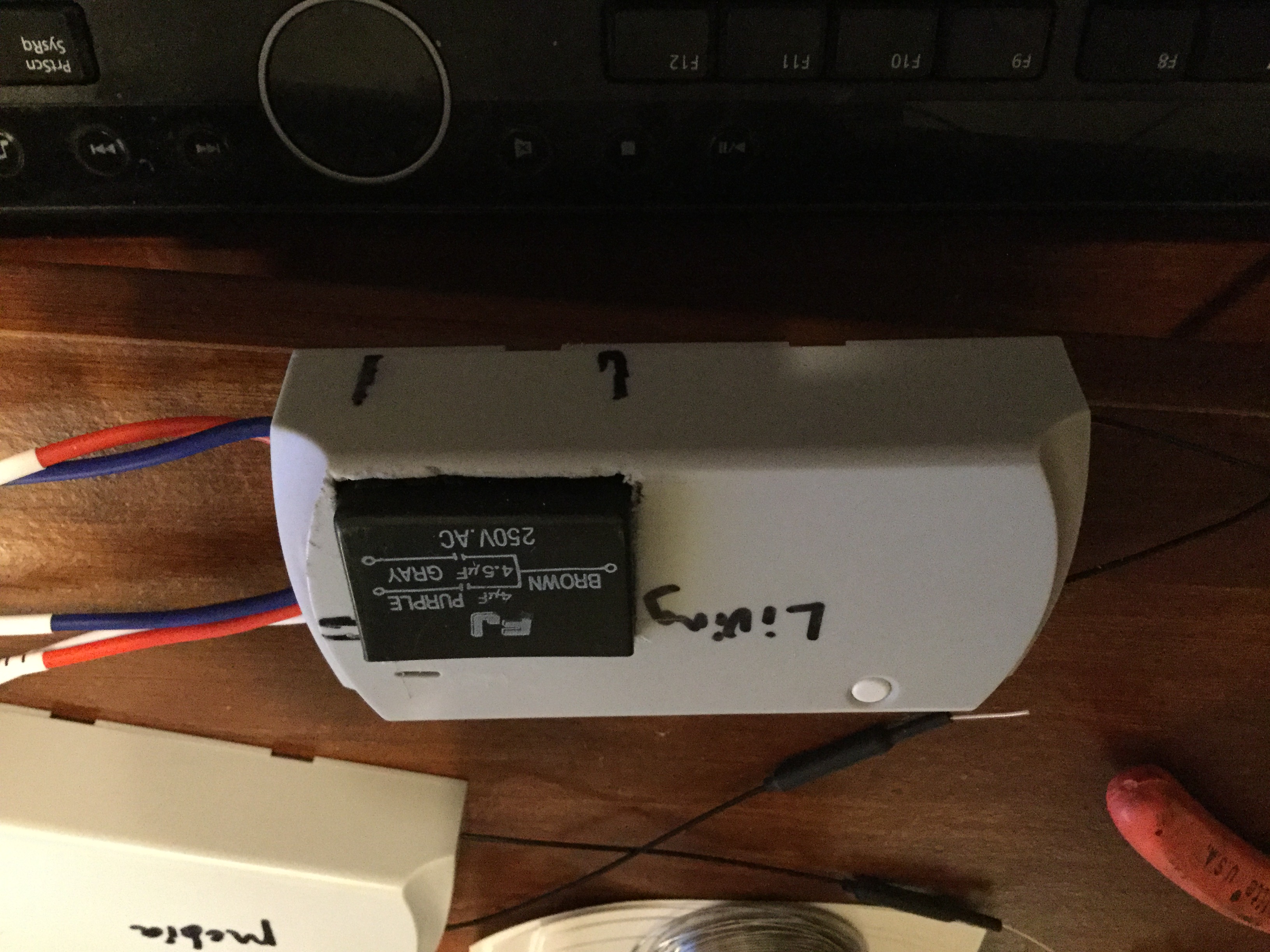
welbo97
on 26 Aug 2018
I like it! keeps the wires down. The first one I did was done externally. I might do what you did there on my next one.
digiblur
on 26 Aug 2018
@welbo97 nice! Got any pics of how you routed the wires internally?
ExplodingLemur
on 26 Aug 2018
@welbo97
https://community.home-assistant.io/t/fan-control-set-speed-working-quick-setup/57520
there was a slight change that needed to be made to the code there but if you read down through the thread for the exchange between me and another user at the end you'll see what needed to be done.
It's pretty straight forward as I recall.
what I saw as the result of FanSpeed 4 was that it returned a RESULT of speed 0. but since the component sends a payload of 4 then immediately a payload of 1, 2 or 3 for the speed setting. the end result is that you end up with the correct state ('on') and speed displayed that matches the real state of the fan.
finity69x2
on 26 Aug 2018
@ExplodingLemur I was about half scared to take the lid off again. It was a pretty tight fit (which I like). This particular cap left just enough room for the two cap wires to run around back and sit between the cap and the lid. The only one I’m not real happy with is the brown wire. It comes from the line voltage, which has the original holes covered up by the new cap. All I could think to do was wrap it around the line input wire where it goes through the board and solder in place. It’s solid, just unconventional. There is also very little clearance between the relays and the lid, as evidenced by the indentations on the brown wire. BUT, since I have access to it again, I just found I can stuff the brown wire between the recess in the bottom of the potted cap and the relays.
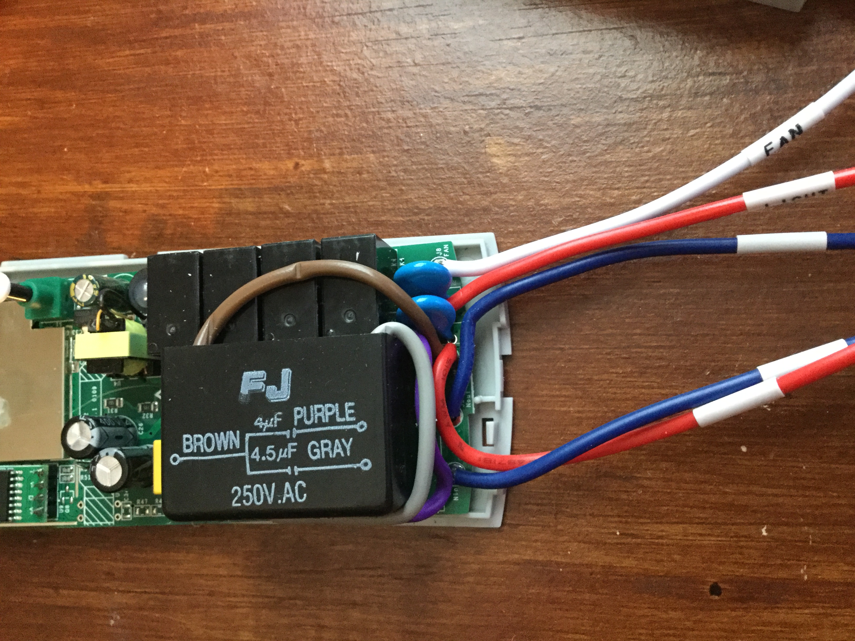
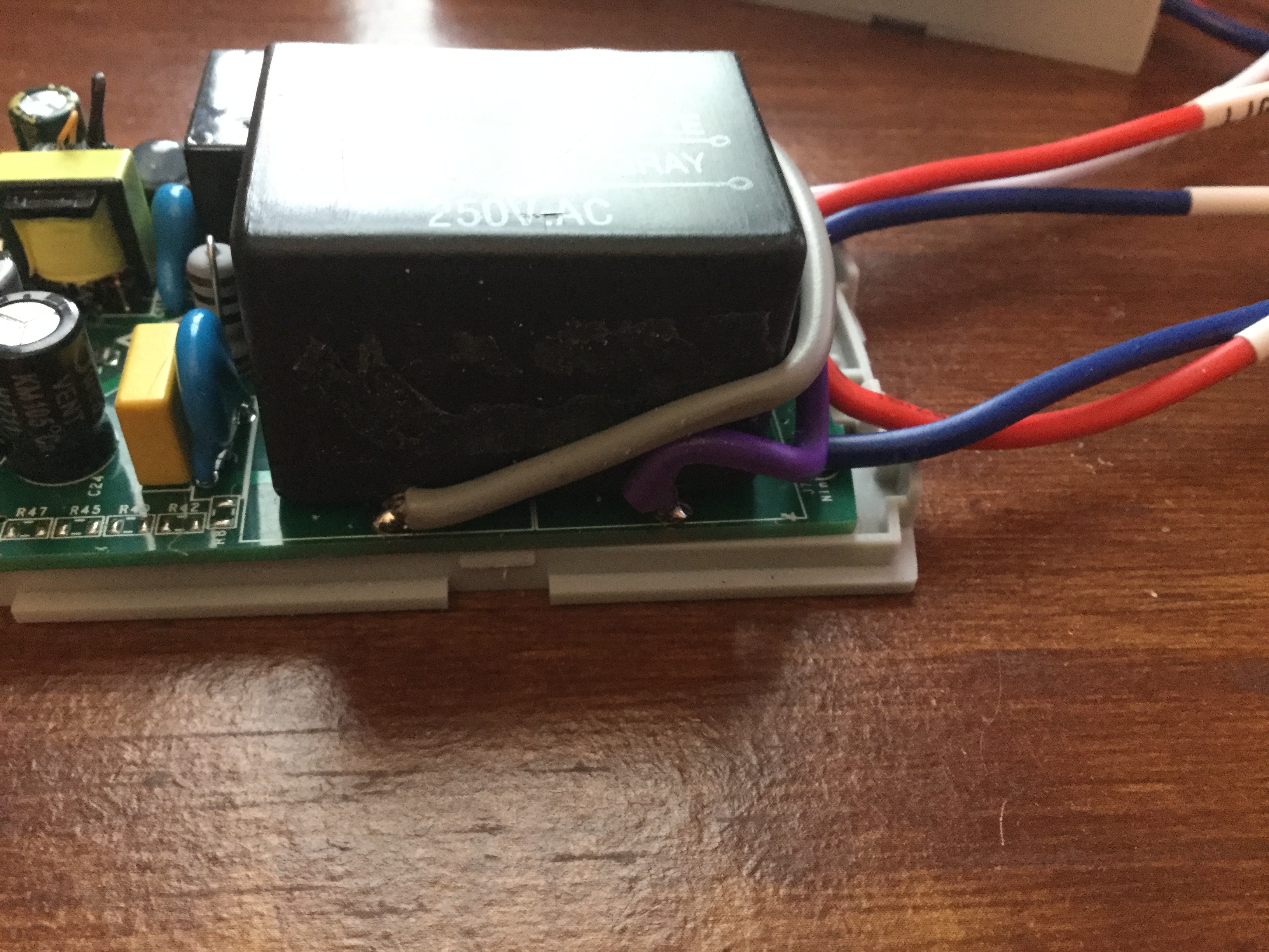
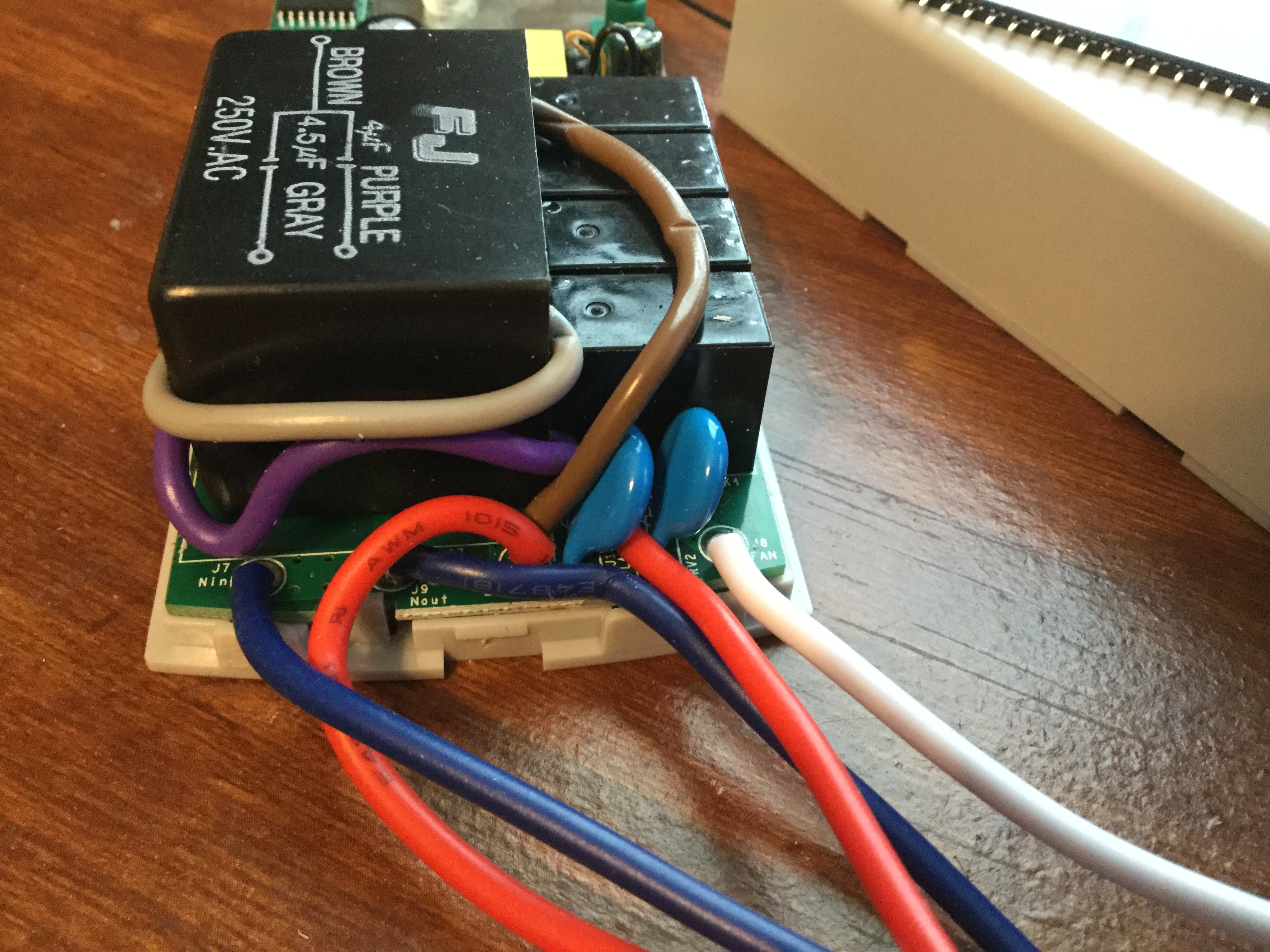
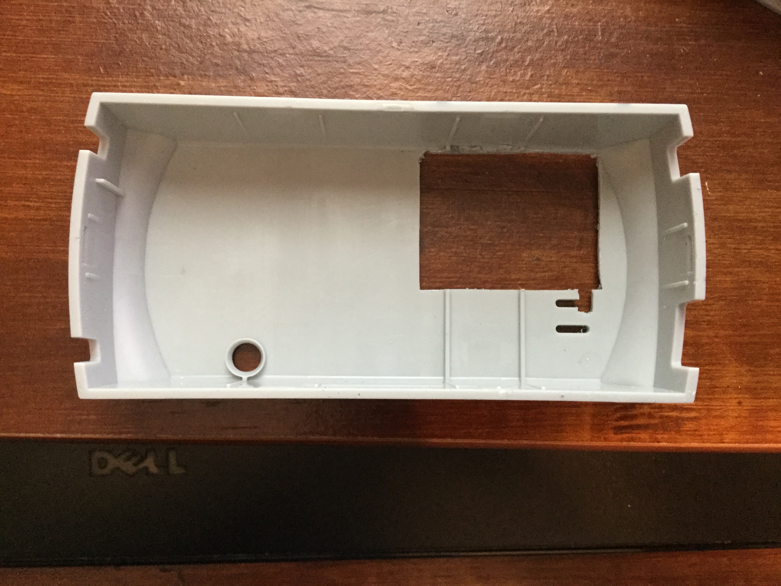
welbo97
on 27 Aug 2018
One thing I just noticed and I'm not sure why it's doing it or how to figure out why...
I put the query code for the status update on Home Assistant restart per the wiki.
It works fine except that every time I send a query message i get a status via RESULT, then I see the stat message also pop up for POWER1.
So this is what I'm seeing in my MQTT log:
send: cmnd/sonoff_fan/POWER1 - ""
return: stat/sonoff_fan/RESULT - {"POWER1": "OFF"}
return: stat/sonoff_fan/POWER1 - OFF
I don't know what that last line is being generated. I don't see another command message that would prompt that status message but I believe the command message is being sent somehow.
And it's messing up my automation that I'm using to turn on & off the light since I don't use the sonoff output directly connected to the light. I'm just using as a relay to control the light via my original controller and a broadlink.
When I get that last message the automation gets triggered to toggle the light state via the broadlink but since the light is off it then comes on, which is undesirable.
any ideas?
Edit to add that I have my light in HA set to "retain: false"
finity69x2
on 28 Aug 2018
That’s how mine acts too. I think it is just built to return both pubs when it receives the cmnd/sonoff_fan/POWER1.
I don’t follow exactly what your setup is but it seems to me that if both pubs are switching your lights you could change whatever is monitoring it to look at a more specific mqtt message. So if it receives “stat/sonoff_fan/POWER1:Off” (or On), it reacts accordingly and ignores the “stat/sonoff_fan/RESULT” json data. Funny, I usually have the opposite problem. One capital or misspelled word and the whole thing doesn’t work.
welbo97
on 28 Aug 2018
@finity69x2 I think I see what you are saying now. When the "sniffer" queries the state on HA startup, the broadlink sees the "stat/sonoff_fan/POWER1" return and switches the lights. Is the broadlink set to toggle the lights or set them to the absolute value? If it is an absolute value, then your sonoff fan, broadlink and HA are simply getting all in sync, as the script is meant to do. If the broadlink is set to toggle the light when commanded, you are having the same delima I'm having with three and four way switches. I can't set the state because the switches can flip the state. I also don't really want to leave the relays powered on all day with the light off.
My two ideas are:
- a light sensor pointed directly at the light, feeding gpio 14, reporting the state.
- Disconnect the output of the 3 and 4 way switches entirely from the light. Instead, turn that 110v output into a 3.3v signal and feed that into gpio 14. Then set the Tasmota firmware up so that a flip of the switch toggles the sonoff relay and reports the state back to mqtt/HA.
I'm leaning toward 2, but I wish I could find a cheap/easy way of turning a 110Vac power output into a 3.3v dc signal voltage. The only solution I have so far is this IRM02-3 I picked up from mouser for $10. But that raises the cost of each switch to $16.
But I digress. Did I answer your question?
welbo97
on 29 Aug 2018
off topic (slightly)
I was connecting an ifan 02 into a westinghouse fan today. I removed the four way rotary switch and the capacitor (0.75uF and 1,25uF) and connected the fan output from the iFan02 directly to the active output from the rotary switch (this connects into the 2 way, 2 pole fan direction switch). The other pole of the direction switch is neutral.
This leaves two wires unconnected to the fan. a grey and a blue. blue is used consistently in the fan for neutral (as is common in Europe). However the fan gets its main neutral from the two way two polie switch. I have tried this connected and unconnected and the same result occurs (see below).
The other unconnected wire is a grey. This is connected directly to the output of the mutli-way capacitor. I assume it is a path to neutral. As with the blue wire, I have tried this connected and unconnected.
In all scenarios, the ifan bleeps properly and i can hear the motor humming. But the blades do not spin (nor the spindle). I didn't have a multimeter on me to test, but something didn't seem right!
unfortunately I had to dismount the cap and rotary switch so the fan is now fairly useless ...
I am assuming for the moment that the ifan02 is not broken. so at the moment I am going with misunderstanding the wiring. Anyone got any ideas (i'm being a tad lazy as I don't want to dismount the whole thing to open up the motor housing and trace the wires).
thanks in advance.
Justin
 jpadie
on 2 Sep 2018
jpadie
on 2 Sep 2018
@jpadie I don’t have an exact answer for you but I thought of some things
you can look at.
- My fans (US) have two caps. One is a “two-way” as you described. The
other is a single potted cap (two wires total). The “two way” is used to
control speed with the rotary switch. The other is a motor starting cap. - If you look a way up this thread, there is a wiring diagram of a hunter
fan that is likely similar to yours. - Some fan motors have two different windings in order to control speed or
direction. My guess is the extra wires coming out of your motor are the
secondary windings. - Make sure you leave or restore the single potted cap back to its
original place as it is probably the motor starting cap.
welbo97
on 2 Sep 2018
Thanks Will
This cap is potted too. It has three wires. The grey is a common wire and the other two connect to the internal cap values above. Externally the grey is the wire that's I'm concerned about. The other two wires connect to the pull switch.
The pull switch has four states.
- Not connected
- Power connected to output
- Power connected to output and a capacitor
- Power connected to output and the other capacitor.
jpadie
on 2 Sep 2018
on the above, the westinghouse fans have a hot going to the primary windings. and a second hot _maybe_ going to the secondary windings via a capacitor.
But with the iFan there is only a hot/neutral pair coming from the module. Do I connect both the primary and secondary windings to the same hot wire?
jpadie
on 3 Sep 2018
@ welbo97
Regarding your mod. Many of these fan caps are three level. With your mod, do you have all three fan speeds and it seems same as the fan was in factory state? In other words, if I have a fan with a three level cap or three caps, can I just use two of the levels from the cap and I'll get all three speeds same or similar to factory state? What's your experience?
 logname
on 11 Sep 2018
logname
on 11 Sep 2018
It depends on what the third cap is used for. My fan had a separate third cap, used as a motor starter. It needed to be in place for all speeds. Assuming your fan already has one in it, the one you put in the ifan02 would just take up extra space.
As for speeds, they aren’t exactly the same. The goal would be to match the impedance of the existing fan. It seems there is a lot of variation from one manufacturer to the next. The parts I had were scavenged from an old fan I threw away and didn’t match the fan where the ifan02 would be installed exactly. But the speeds are more reasonable. In the “low” mode, the ifan02 produced a speed that wasn’t of much use (too slow) because it was only using the 2uf cap. With the replacement, power is now routed through a 4uf cap on low. And that makes a better low speed.
welbo97
on 11 Sep 2018
Fan cap was two level.The speeds are not identical but close enough not to be bothersome. Top speed is identical. On 11 Sep 2018 4:27 p.m., Douglas Krug notifications@github.com wrote:@ welbo97
Regarding your mod. Many of these fan caps are three level. With your mod, do you have all three fan speeds and it seems same as the fan was in factory state? In other words, if I have a fan with a three level cap or three caps, can I just use two of the levels from the cap and I'll get all three speeds same or similar to factory state? What's your experience?
—You are receiving this because you were mentioned.Reply to this email directly, view it on GitHub, or mute the thread.
jpadie
on 11 Sep 2018
Thanks for the quick responses. I'm thinking of just running wires in place of each cap and tapping into the existing caps in the fan so I would essentially be permanently bypassing the pull chain. I'd be concerned about doing this if it were not for the included remote which seems to very reliable.
logname
on 11 Sep 2018
Hi,
I have used the code form the tasmota wiki for my ifan but i only see one button. (see image)
fan:
  - platform: mqtt
    name: "Master Bedroom Fan"
    command_topic: "cmnd/sonoff_MBR_fan/FanSpeed"
    speed_command_topic: "cmnd/sonoff_MBR_fan/FanSpeed"
    state_topic: "stat/sonoff_MBR_fan/RESULT"
    speed_state_topic: "stat/sonoff_MBR_fan/RESULT"
    state_value_template: >
      {% if value_json.FanSpeed is defined %}
        {% if value_json.FanSpeed == 0 -%}0{%- elif value_json.FanSpeed > 0 -%}4{%- endif %}
      {% else %}
        {% if states.fan.master_bedroom_fan.state == 'off' -%}0{%- elif states.fan.master_bedroom_fan.state == 'on' -%}4{%- endif %}
      {% endif %}
    speed_value_template: "{{ value_json.FanSpeed }}"
    availability_topic: tele/sonoff_MBR_fan/LWT
    payload_off: "0"
    payload_on: "4"
    payload_low_speed: "1"
    payload_medium_speed: "2"
    payload_high_speed: "3"
    payload_available: Online
    payload_not_available: Offline
    speeds:
      - off
      - low
      - medium
      - high

 benmprojects
on 14 Sep 2018
benmprojects
on 14 Sep 2018
I just responded to your post on the Home Assistant forum... check here: https://github.com/arendst/Sonoff-Tasmota/wiki/Home-Assistant#ifan02-1
mjoshd
on 14 Sep 2018
Hello,
I connected the ifan02 to my Vortice ceiling fan. in all three speeds the engine runs too fast.
is there a possibility to reduce the number of fan revolutions? the output voltage of the ifan02 can be lowered from the tasmot firmware. or is there any other possibility?
I am now like this:
- max: tornado
- med: wind storm
- low: elicopter
 madmicio
on 23 Sep 2018
madmicio
on 23 Sep 2018
@madmicio
how did you connect the module?
is there a manual speed setting on the fan too? if so what is that set to?
the settings on the ifan02 via tasmota correspond to 1 cap, 2 caps, no caps. in my module each cap is 3uF across 200kOhms. so although you _can_ change the speed config in the firmware there is no value at all in doing so.
you need to calculate the total capacitance of the circuit with each configuration to work out what mirrors your existing set up the best.
in my installation there is still something awry as although the speeds work fine, the motor hum on full speed is very bad.
jpadie
on 23 Sep 2018
I'm sure this isn't the best place to ask this but it seems the community here is more in tune with what's under the hood than anywhere else. Has anyone looked into or uncovered the 2.4 gHz remote protocol? Reason I'm asking is one of mine came with the battery cover slightly deformed and as such it won't close completely. That got me to thinking that maybe I should seek some other universal remote replacement that could be programmed to do the same thing buth with a slightly better build quality.
 bwze
on 26 Sep 2018
bwze
on 26 Sep 2018
@bwze
You are right that the folks in this thread have a lot of the hardware understanding. There really isn't a place other than here to discuss the hardware issues.
I have one remote that is "bad" in that it eats a battery every 3-4 days, so your thought about a different remote setup resonates with me.
What I know about the remote is that it is 2.4 GHz and the markings on the remote board start with "BT". Together, that leads me to suspect that it's using a bluetooth protocol. I haven't tried sniffing it yet and don't have much experience with BT. I think the use of BT might explain why there is an ARM processor for the remote "There is an arm just for the remote? god, why?" (comment from way up top). Credit to @abzman
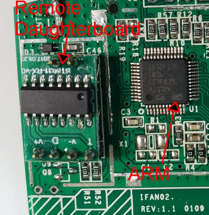
As far as ideas for a better remote, a few modalities come to mind but the one I like the best is an ESP that just sends MQTT messages on button presses. It can be put into deep sleep when not in use like other IR remotes. Whether this can be implemented in a tidy package with a reasonable battery draw is the question. With my remote being buggy, I am usually using my phone to control the fan via MQTT either through homeassistant or Tasker MQTT publish.
Itead has not responded to my request for a replacement, which is par for the course.
jumblies
on 26 Sep 2018
Curious what the other iFan02 people see when they send a "power2 2" command. It looks like it works for me in toggling but the GUI or console do not reflect that. Are you seeing the same?
From the commands wiki:
Power
digiblur
on 26 Sep 2018
What are you trying to achieve by sending a power2 command?
From limited testing it looks like power2 is a pseudo for fanSpeed.
I would not have thought it supported a toggle command. But I cannot test that until the morning.
jpadie
on 27 Sep 2018
Trying to achieve a toggle from a button. Much like you would have a button send a toggle to the power1 relay to turn the light on and off. Sending the power2 2 to toggle does seem to work as it does physically toggle on and off but it produces the wrong state for me when it is really off.
Use case example. Wemos D1 mini with a button between D1 and GND. When it is pulled low it has a rule to send over "power2 2" to the fan to turn the fan on and off.
digiblur
on 27 Sep 2018
Sending toggle to power2 seems to switch from fanSpeed 0 to 1 and back.
I'm sure you could change the code to do differently should you wish.
The way I have it set up is that a sonoff touch acts as the on/off for the light and the second button for the fan speed. The second button sends a message to a knx group address and the fan listens for that message and executes a + command on receipt. The + is currently coded in tasmota to go from fan speed 0 (off) through 1,2 and 3 and then back to 0. So kind of like a toggle but more useful for fan speed.
jpadie
on 27 Sep 2018
It stays as fanspeed 2 in the console but does shut off.
That method is a little out of my realm as I don't have knx setup and it is an on/off button to turn off the fan.
digiblur
on 27 Sep 2018
can you draw or photograph your setup and wiring?
also perhaps post the status info from your module.
this is the output from the console that I receive
`
10:38:33 CMD: power2 toggle
10:38:33 MQT: hannah/fan2/stat/RESULT = {"FanSpeed":1}
10:38:45 CMD: power2 toggle
10:38:45 MQT: hannah/fan2/stat/RESULT = {"FanSpeed":0}
`
if your switch is attached to the sonoff then consider using switchmode and switchtopic to send an mqtt command of /prefix/topic/cmnd/fanspeed and a message of +
jpadie
on 27 Sep 2018
Ok, so i've read through this whole thread, and a bunch of other pages on the wiki trying to figure this out, my remote doesn't seem to stay paired - but thats a whole other problem... I'm going to spend a few more hours on it tomorrow to try and figure it out.
What I am trying to do is figure out how to use external switches to control the light and fan with the intention of using the RX/TX GPIOs (unless there are any other pins I can access?)
GPIO1 Serial Out: Light on / off
GPIO3 Serial In: Fan 0 > Fan 1 > Fan 2 > Fan 3
Is this possible? What commands do I need to do in the console to achieve this?
Thank you in advance! I've been wracking my brain over this and the broken RF remote all night!
 stewface
on 2 Oct 2018
stewface
on 2 Oct 2018
yes. possible with rules. not sure about using the serial pins though.
the remote pairing issue sounds hardware related. it is not handled by the ESP chip.
jpadie
on 2 Oct 2018
@stewface yes you can use the serial pins. Be careful to not hold GPIO1 low during boot! I covered this in my recent video on expanding the Sonoff Basic (link below). This spoiled my plans but I can confirm a MCP23017 over i2c works great to expand the two pins on the iFan02. I plan on doing a video on it in the next couple weeks on my YouTube channel when I cover the iFan02 and it's quirks.
The rules aren't that hard to get going which actually you might not have to do one for the light if you assign it as switch1. As noted about I did have the issue with the toggle on the fanspeed "relay" but I haven't had a chance to circle back to it yet for additional testing but you should be fine since you are sending the fan speed to it which is possible sending the fanspeed + message.
digiblur
on 2 Oct 2018
Thanks @digiblur
I might need to just use a sonoff basic for the light switch then as I am using on/off switches (match all the 240v switches in the house) not momentary (thus it's a 50/50 chance it could be set to the on position during power failure) so I will save the one GPIO left to control (cycle through) the fan speeds only. (I really want to make sure I have a fail safe control on everything home automation - that will work without wifi, without my hass box working, without internet, if the wife can't turn on the fan in the bedroom one day all my home automation will need be ripped out of the house ;)
Thanks for the link to the video, I had a quick look through, still a bit confused though - any other materials (besides the wiki) on rules that could help me get up to speed on how it works?
How do we know the reference to the relays for the fans to toggle them or how do we add "FanSpeed +" as a command in a rule?
Am I on the right track with this?
rule1 on switch2#state=toggle do FanSpeed +
stewface
on 3 Oct 2018
@stewface I haven't directly tested that rule but the command is FanSpeed with a + payload so it sounds like that should work. I have one setup through NodeRed via MQTT doing that. You might have to assign that switch as Switch3 though otherwise I think it would attach itself to the fan speed. One of those things you have to try on the bench.
digiblur
on 3 Oct 2018
@stewface You are onto something with making sure control remains if automation fails. I am pondering the same thing as you. The most elegant solution I’ve thought of is using the AC switched voltage from the existing wiring to signal the sonoff whether it should be on or off. I found a small AC-3V3 converter for $10. It is a 25W power supply so I would imagine there is something even smaller and cheaper that delivers signal level power.
With one of those power converters, you could have a regular wall switch for the light. In the case of fan speed, I opt to use the old pull chain as my backup. The fan controller boots to full speed, then mqtt retain puts it back where it was before the reboot. In the case of lost HASS, it would boot to full speed, then the chain can be used to modulate.
But if you really want to control speed with the wall switch as a backup, a simple NO push button mounted on the wall switch and connected to a gpio would work with the fanspeed + rule you’ve developed.
Even another sonoff would provide a 3v3 Power signal for only $6. But I’m looking for something very small. Hopefully I can fit it all in the junction box.
welbo97
on 3 Oct 2018
Thanks @digiblur I will have a play today see what progress I make.
@welbo97 - yep everything automated in my house needs basic control outside automations, assume power is off to all methods of control (except the actual device) thinking would it work in a blackout with a generator just powering that device / circuit. (no server, no wifi, no ethernet/hub/communication, basically inside a faraday cage)
The wife was put on a back foot with my early home automation endeavours that were cheap unreliable stuff, thus everything needs to always work no matter what.
stewface
on 3 Oct 2018
Can anyone confirm what the top blank connector pins at the top of the board are?
SWDOI
SWCLK
Labels are written on the other side
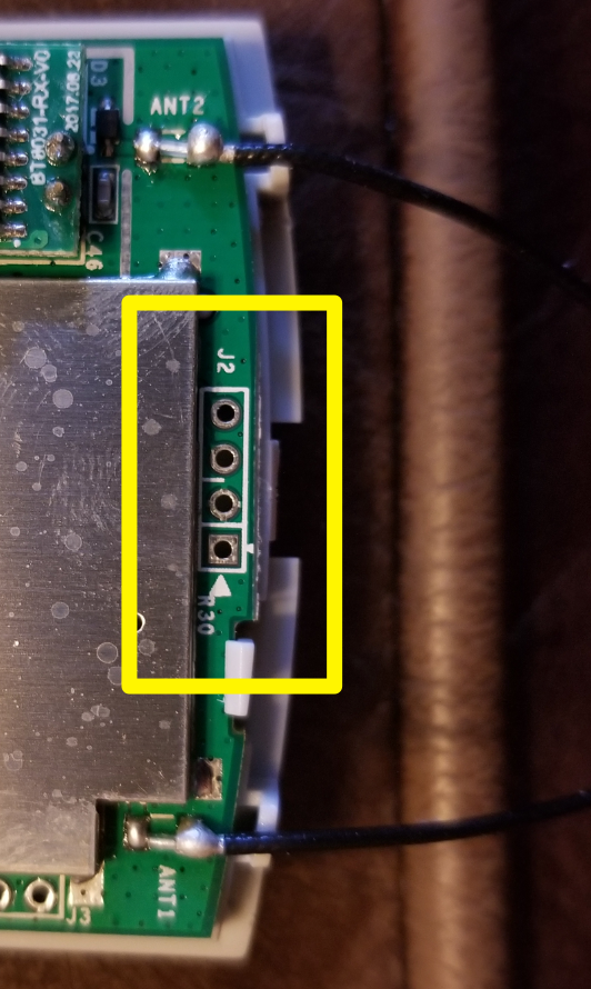
stewface
on 3 Oct 2018
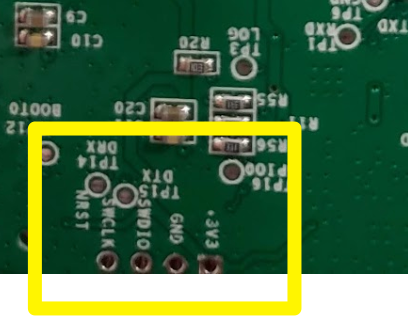
stewface
on 3 Oct 2018
Worth noting I was having a world of pain trying to get the GPIOs working, somehow the unit seem to have done a factory reset - I didn't know / try to activate it (removing even my wifi details I uploaded with tasmota) after that the GPIOs started working.
No luck getting the remote control working, but i'm almost getting to a point where I am going to give up and just put it into the wall without a remote and rely on alexa for control.
stewface
on 3 Oct 2018
I believe those are pins for the other MCU.
digiblur
on 3 Oct 2018
I can confirm that this command in the console doesn't incrementally increase speed when using the GPIO as a switch
rule1 on switch3#state=toggle do FanSpeed +
Not sure what options I have to give something else a shot.
Currently what it does is it will toggle it to the speed 2 from what was set via the web interface (e.g if its off to goes off > 2 off > 2 if I set it to 1 it will go 1 > 2 > 1 > 2 etc.)
I don't really know enough about rules to give anything else a try - any tips in here people?
stewface
on 3 Oct 2018
What does Fanspeed + do in the console? Mine was on 2 at first, it then goes to 3, then 0 then 1, then back 2 is where I stopped it.
digiblur
on 3 Oct 2018
Works perfectly in the console.
06:47:59 CMD: fanspeed +
06:47:59 MQT: stat/sonoff-fan-master/RESULT = {"FanSpeed":2}
06:48:10 CMD: fanspeed +
06:48:10 MQT: stat/sonoff-fan-master/RESULT = {"FanSpeed":3}
06:48:13 CMD: fanspeed +
06:48:13 MQT: stat/sonoff-fan-master/RESULT = {"FanSpeed":0}
06:48:14 CMD: fanspeed +
06:48:14 MQT: stat/sonoff-fan-master/RESULT = {"FanSpeed":1}
06:48:16 CMD: fanspeed +
06:48:16 MQT: stat/sonoff-fan-master/RESULT = {"FanSpeed":2}
06:48:22 CMD: fanspeed +
06:48:22 MQT: stat/sonoff-fan-master/RESULT = {"FanSpeed":3}
stewface
on 3 Oct 2018
Works perfectly in the console -
07:05:16 CMD: fanspeed +
07:05:16 MQT: stat/sonoff-fan-master/RESULT = {"FanSpeed":3}
07:05:18 CMD: fanspeed +
07:05:18 MQT: stat/sonoff-fan-master/RESULT = {"FanSpeed":0}
07:05:24 CMD: fanspeed +
07:05:24 MQT: stat/sonoff-fan-master/RESULT = {"FanSpeed":1}
07:05:26 CMD: fanspeed +
07:05:26 MQT: stat/sonoff-fan-master/RESULT = {"FanSpeed":2}
07:05:30 CMD: fanspeed +
07:05:30 MQT: stat/sonoff-fan-master/RESULT = {"FanSpeed":3}
Now i've tried a bunch of options - nothing seems to work.
06:58:43 CMD: rule1 on switch3#state=on do FanSpeed +
06:58:43 MQT: stat/sonoff-fan-master/RESULT = {"Rule1":"OFF","Once":"OFF","StopOnError":"OFF","Free":478,"Rules":"on switch3#state=on do FanSpeed +"}
06:58:46 MQT: stat/sonoff-fan-master/RESULT = {"FanSpeed":1}
06:58:49 MQT: stat/sonoff-fan-master/RESULT = {"FanSpeed":2}
06:58:51 MQT: stat/sonoff-fan-master/RESULT = {"FanSpeed":1}
06:58:53 MQT: stat/sonoff-fan-master/RESULT = {"FanSpeed":2}
06:59:21 CMD: rule1 on switch3#state=toggle do FanSpeed +
06:59:21 MQT: stat/sonoff-fan-master/RESULT = {"Rule1":"OFF","Once":"OFF","StopOnError":"OFF","Free":474,"Rules":"on switch3#state=toggle do FanSpeed +"}
06:59:24 MQT: stat/sonoff-fan-master/RESULT = {"FanSpeed":1}
06:59:26 MQT: stat/sonoff-fan-master/RESULT = {"FanSpeed":2}
06:59:29 MQT: stat/sonoff-fan-master/RESULT = {"FanSpeed":1}
06:59:29 MQT: stat/sonoff-fan-master/RESULT = {"FanSpeed":2}
06:59:29 MQT: stat/sonoff-fan-master/RESULT = {"FanSpeed":1}
06:59:31 MQT: stat/sonoff-fan-master/RESULT = {"FanSpeed":2}
07:00:46 CMD: rule1 on switch3#state do FanSpeed +
07:00:46 MQT: stat/sonoff-fan-master/RESULT = {"Rule1":"OFF","Once":"OFF","StopOnError":"OFF","Free":481,"Rules":"on switch3#state do FanSpeed +"}
07:00:49 MQT: stat/sonoff-fan-master/RESULT = {"FanSpeed":1}
07:00:50 MQT: stat/sonoff-fan-master/RESULT = {"FanSpeed":2}
07:00:51 MQT: stat/sonoff-fan-master/RESULT = {"FanSpeed":1}
07:00:53 MQT: stat/sonoff-fan-master/RESULT = {"FanSpeed":2}
07:02:27 CMD: rule1 on button3#state
07:02:27 MQT: stat/sonoff-fan-master/RESULT = {"Rule1":"OFF","Once":"OFF","StopOnError":"OFF","Free":494,"Rules":"on button3#state "}
07:02:31 MQT: stat/sonoff-fan-master/RESULT = {"FanSpeed":1}
07:02:33 MQT: stat/sonoff-fan-master/RESULT = {"FanSpeed":2}
07:02:35 MQT: stat/sonoff-fan-master/RESULT = {"FanSpeed":1}
07:02:37 MQT: stat/sonoff-fan-master/RESULT = {"FanSpeed":2}
stewface
on 3 Oct 2018
What version of tasmota are you using? Have you traced the execution back in the code to see whether there is a bug in the rule parsing? That's what the behaviour looks like to me.
jpadie
on 3 Oct 2018
Why are you omitting the endon by the way?
rule1 on switch3#state do FanSpeed + endon.
NB switchtopic must be 0
jpadie
on 3 Oct 2018
Program Version | 6.2.1
-- | --
2018-09-09T16:50:26
Why are you omitting the endon by the way?
That's above my pay grade (I have no idea what that is.. but I will try and read up on it now!)
stewface
on 3 Oct 2018
That's above my pay grade (I have no idea what that is.. but I will try and read up on it now!)
Every on requires an endon - so without it you have something similar to a non-ended loop.
 andrethomas
on 3 Oct 2018
andrethomas
on 3 Oct 2018
Thank you @andrethomas & @jpadie and everyone else who helped!
I finally got it!
If anyone wants to setup a single push button switch attached to the GPIO that will cycle through the speeds and turn off - after setting it in the configuration the code is:
rule1 on switch3#state do FanSpeed + endon
This will cycle up the speeds until it turns off, then repeat.
07:30:05 MQT: stat/sonoff-fan-master/RESULT = {"Rule1":"ON","Once":"OFF","StopOnError":"OFF","Free":475,"Rules":"on switch3#state do FanSpeed + endon"}
07:30:07 RUL: SWITCH3#STATE performs "FanSpeed +"
07:30:07 MQT: stat/sonoff-fan-master/RESULT = {"FanSpeed":3}
07:30:07 RUL: SWITCH3#STATE performs "FanSpeed +"
07:30:07 MQT: stat/sonoff-fan-master/RESULT = {"FanSpeed":0}
07:30:08 RUL: SWITCH3#STATE performs "FanSpeed +"
07:30:08 MQT: stat/sonoff-fan-master/RESULT = {"FanSpeed":1}
07:30:09 RUL: SWITCH3#STATE performs "FanSpeed +"
07:30:09 MQT: stat/sonoff-fan-master/RESULT = {"FanSpeed":2}
07:30:09 RUL: SWITCH3#STATE performs "FanSpeed +"
07:30:09 MQT: stat/sonoff-fan-master/RESULT = {"FanSpeed":3}
stewface
on 3 Oct 2018
@stewface Happy you got it working. When you get some time please add your information to the Wiki ;)
Thanks again!
andrethomas
on 3 Oct 2018
I feel I have achieved something and did my part and added that to the wiki
Now can anyone help me with this freaking remote! I've tried everything! It never worked to begin with (but I didn't try it before flashing) after flashing i pressed it heard some beeps, but then it stopped.
I read above (thanks @ExplodingLemur ) that you can re-pair it by opening up the remote and pressing the hidden button while you power cycle the unit
Yep. In order to get the RF remote to re-pair with the controller I power-cycled the controller while holding a button inside the RF remote case (pop the back of the case off, hold the battery in place, and press and hold the button)
I've done that, with minimal success - after about 50 attempts I think 3-4 times I could get a button press to activate a beep and change status, and only then it would do it maybe 2 minutes and it would unpair.
My process:
1- power off device (wait 10 seconds) - prepare with plug hanging out for easy boot
2- prepare remote with battery held by tape to avoid it coming off
3- press hidden remote button side case (wait for flashing LED) - quickly
4- boot up device
5 - wait for failure
Occasionally i get a beep, most of the time i dont and the remote is dead, when i get a beep sometimes i get a few working button presses before that come through to the web gui, but then it stops working again.
I tried @ExplodingLemur trick with desoldering the RF draughtboard - that hasn't helped
I even made sure it wasn't an I.D. 10 T error as @jumblies found with a flat battery (I have even tried two batteries and checked them both with a multi meter)
@finity69x2 you mentioned you have had luck re-pairing the remote?
What other options do I have here? Is there any other secret button combos I can press to fix it, any way to any sort of debugging information from the device to find out what is happening?
stewface
on 3 Oct 2018
@stewface
Any way to get the fan working with a toggle switch? I just want it to turn on/off the fan (on to the previous state). Leaving the fan speed control to the remote.
 raghavrithvik
on 3 Oct 2018
raghavrithvik
on 3 Oct 2018
Send a toggle over as the payload instead of + or -
digiblur
on 3 Oct 2018
I don't think toggle is reliable.
use case:
set fanSpeed = 3
send a fanspeed toggle command
(fan speed changes to 2)
send a fanspeed toggle command
(fan speed stays at 2).
send a power2 toggle command and the fanspeed stays at 3.
there's probably a better solution using Rules. Perhaps follow the "simple" thermostat example.
jpadie
on 3 Oct 2018
Yep. That was my issue as well, the power2 toggle works but it has status issues.
digiblur
on 3 Oct 2018
something like this perhaps?
Mem2 = <your default on speed>
rule 1 on switch3#state=1 do fanspeed Mem2 endon on switch3#state=0 do fanspeed 0 endon
(nb not tested at all).
jpadie
on 3 Oct 2018
WOW... after all that... turns out the remote doesn't work when powering from 3.3v (for me anyway)
Works with 240v fine.
stewface
on 3 Oct 2018
No. It doesn't. There is a note about that on one of the sonoff touch threads.
jpadie
on 3 Oct 2018
A lot of stuff doesn't work off 3v3 like 5vdc relays on boards and such as well.
digiblur
on 3 Oct 2018
Successfully installed tasmota V6.2.1 on sonoff ifan2 device
What is annoying to me is the beep whenever switching between fan modes.
Is there a possiblity to switch off/on the beep via a command?
I control the fan both, via remote control and nodered commands
Best
Jens
 jk2020
on 4 Oct 2018
jk2020
on 4 Oct 2018
Turn off the beep on the RF remote.
arendst
on 4 Oct 2018
Not bad ;-) yes, that works.
But is there also a command I could send?
As mentioned I used also node-red to control the fan
jk2020
on 4 Oct 2018
Nope. It's handled by the second microcontroller.
arendst
on 4 Oct 2018
New question:
If I press remote control fan #2 following commands are shown
stat/sonoff-ifan2/RESULT = {"FanSpeed":1}
stat/sonoff-ifan2/RESULT = {"FanSpeed":2}
If I press remote control fan #3 following commands are shown
stat/sonoff-ifan2/RESULT = {"FanSpeed":1}
stat/sonoff-ifan2/RESULT = {"FanSpeed":3}
Is it possible to change that, so that for fan #2 one is sent
stat/sonoff-ifan2/RESULT = {"FanSpeed":2}
and for fan #3 only one command is sent
stat/sonoff-ifan2/RESULT = {"FanSpeed":3}
Reason behind that request; I want to feed the status back to node-red but having multiple commands for changing one status are causing trouble and my device is behaving like a flipflop switchin always between 1 and 3 or 1 and 2.
jk2020
on 4 Oct 2018
I am a sonoff newbie, and I was able to flash the iFan 02 without too much trouble. Read out the factory image, erased, loaded on current tasmota. I am unable to get it on wifi - pressing the button 4 times doesn't seem to put it AP mode. Any ideas?
 vmarks
on 26 Oct 2018
vmarks
on 26 Oct 2018
Hard to say without knowing what the serial output is.
Can you tell us what the sonoff is saying over serial?
jumblies
on 26 Oct 2018
I'm not sure how to do that - I do have an arduino uno in the house, but I loaded the firmware using a CP2012 and esptool.
vmarks
on 26 Oct 2018
The cpxxxx/uart that you used to load the firmware will work for a Serial
adapter. You just need to open a terminal to the serial adapter. If you
have an IDE install, such as Arduino, they have a built-in terminal that
you can use to read the serial output and issue serial commands. That is
the easiest way to get Wi-Fi up and running. Any command you can issue on
the console through the web interface can be issued via serial terminal.
Figuring that out is step 1. Get that up and then of you're still stuck
come back. I believe the wiki has some good info to get u sorted
On Oct 26, 2018 8:31 AM, "Victor Marks" notifications@github.com wrote:
I'm not sure how to do that - I do have an arduino uno in the house, but I
loaded the firmware using a CP2012 and esptool.—
You are receiving this because you were mentioned.
Reply to this email directly, view it on GitHub
https://github.com/arendst/Sonoff-Tasmota/issues/2839#issuecomment-433391775,
or mute the thread
https://github.com/notifications/unsubscribe-auth/AXFbv56ZNMqnbL3xwNQsYrTlXuag2zMXks5uowC-gaJpZM4UPDk4
.
jumblies
on 26 Oct 2018
OK, I have Arduino installed. I have it set to use the cp2012 as the port. Arduino has Serial Monitor and Serial Plotter. With the cp2012 connected physically to the ifan02, nothing shows up in either window.
vmarks
on 26 Oct 2018
I also attempted to use a terminal called Serial. it connects, but nothing shows in the terminal.
vmarks
on 27 Oct 2018
follow up: it isn't saying anything over serial, at all.
I upload like so:
esptool.py --port /dev/tty.SLAB_USBtoUART write_flash -fs 1MB -fm dout 0x0 firmware.bin
esptool.py v2.5.1
Serial port /dev/tty.SLAB_USBtoUART
Connecting....
Detecting chip type... ESP8266
Chip is ESP8285
Features: WiFi, Embedded Flash
MAC: 84:0d:8e:47:ad:1d
Uploading stub...
Running stub...
Stub running...
Configuring flash size...
Compressed 499920 bytes to 343029...
Wrote 499920 bytes (343029 compressed) at 0x00000000 in 30.3 seconds (effective 132.1 kbit/s)...
Hash of data verified.
Leaving...
Hard resetting via RTS pin...
and when I connect to it via a terminal to see any output, it's just blank.
vmarks
on 27 Oct 2018
Hi.. Does there exist a illustrated guide or a video of have to flash ifan2 with Tasmota.. have tried to read all comments, but I haven’t managed to find a link.. I have only flashed a Sonoff basic before about a week ago, so all the help I can get, will be fantastic :)
 darkice555
on 27 Oct 2018
darkice555
on 27 Oct 2018
@vmarks
You say you flashed the module over serial and then "connected to it via a terminal".
Just to be clear, did you change the hardware connections between flashing and "connecting to it via a terminal"? You should not have.
Please give some information about the steps you took to "connect to it via a terminal".
Have you checked your router to see whether the ifan is connecting to your WiFi network?
Note that the module will be unlikely to do much, if anything, if you are powering it from your usb port (but you should see serial output unless your computer has shut off the usb port). The current limitation will probably cause it to go into reset loops or not power up altogether if your computer has shut off the usb port . And of course do not attach it to your computer whilst the module is powered by the mains. You need a stable bench power supply or decent lithium cell to power it whilst testing.
jpadie
on 27 Oct 2018
@jpadie
Those are all really good thoughts that I should have said before. Thanks for jumping in.
@vmarks
If you are getting that output from the ESPTtool, it seems likely that your connection and serial interfacing are ok. If you power it from USB only, you'll likely get nothing or garbage on a serial monitor.
A few things to consider that no one ever says explicitly because we've all facepalmed our way through. Only one app can use the serial monitor at a time. If you have a terminal open and then look in another terminal, it wont work. No error message, just nothing. This has wasted man-years of time for arduino newbs.
Also, make sure you are not putting your iFan into flash mode when booting. You won't see any output in flash mode.
It is difficult if not impossible to troubleshoot without serial output. You appear to be using the precompiled binaries so you can't set a wifi at compilation.
The iFan with a successful tasmota install will have plenty of serial output if everything is configured right (by this I mean good power to ifan, correct UART wiring, and correct drivers on the PC).
Start with basics: test the loopback on you UART adapter, if you have another sonoff, check and see if you can flash tasmota and get serial output on that device.
The iFan is an intermediate to advanced user level device (in terms of hacking it) and not without problems even in the best of hands, so not a great one to cut teeth on. I'm not trying to discourage, but most of us ran into at least one stumbling block on the way to success.
jumblies
on 27 Oct 2018
Flashing in esptool.py in a shell.
Uploading either a prebuilt sonoff.bin, or building one in platformIO, because I wanted to insert my wifi details. I also wanted it to default to being its own AP if it can't find Wi-Fi (which honestly, seems like a good idea for new users in general.)
The output for flashing is:
`esptool.py v2.5.1
Serial port /dev/tty.SLAB_USBtoUART
Connecting....
Detecting chip type... ESP8266
Chip is ESP8285
Features: WiFi, Embedded Flash
MAC: 84:0d:8e:47:ad:1d
Uploading stub...
Running stub...
Stub running...
Configuring flash size...
Compressed 500496 bytes to 342793...
Wrote 500496 bytes (342793 compressed) at 0x00000000 in 30.3 seconds (effective 132.4 kbit/s)...
Hash of data verified.
Leaving...
Hard resetting via RTS pin...`
I did figure out only one terminal app can connect to it at a time. That's fine. I can connect to it using either Serial Tools (Mac) or Visual Studio / PlatformIO. The result is the same. It connects, nothing is displayed. When I press return on my keyboard, I can see the LED flash on the UART adapter. my serial port is /dev/tty.SLAB_USBtoUART
I did connect iFan's AC lines to power while trying to connect to it in Visual Studio's terminal. No output in terminal. When I look for it at my router, it's not showing up as a DHCP client - I'm looking for it by its MAC address. Router is a synology rt2600ac, no repeaters, no mesh networking, 2.4 and 5 ghz networks enabled. It should be able to join.
Drivers and UART connections appear to be correct: I can flash it and it uploads successfully. I can press return in a connected terminal and see LED flashes on the UART. Holding down the button is required to get it into firmware flashing mode, which suggests that I soldered the GPIO to gnd and header correctly.
This is my first Sonoff device. I'm okay with it being a bit of an uphill struggle initially. I just need to get one working. so that I can do it repeatably.
My desired end goal is to get this working in HomeAssistant, and then operate it through its remote control and HomeKit via HomeAssistant's HomeKit plugin. If I can get one working, I'm planning on setting four more.
vmarks
on 27 Oct 2018
Please don't power with AC whilst plugged in to your laptop. Genuine chance of death.
Use a bench power supply or a decent 3.3v source.
Make sure you are connecting at 115200baud as even when in download or user code mode you should get something on the terminal. Providing there is enough power.
jpadie
on 27 Oct 2018
the CP2102 UART provides enough power on 3.3v to flash decently. I will re-try with 115200 explicitly set (I know I had set at one point to 57600).
Another option is I have an arduino uno and can use a transformer with it, if we think power is the issue here.
vmarks
on 27 Oct 2018
https://github.com/arendst/Sonoff-Tasmota/wiki
That’s a great place to start. The menu on the right has links to flashing procedure several different ways. For an ifan02 without access to a power supply, I’d suggest using SonOTA, (Over-The-Air). If you want to flash via serial, read through ‘prerequisites’ ‘Hardware prep’ and ‘upload’. Then look at the hardware specific page for the ifan02: https://github.com/arendst/Sonoff-Tasmota/wiki/Sonoff-iFan02
For flashing, getting the ifan02 into flash mode is probably the most challenging. You have to connect the tiny ‘TP16’ test point to ground while booting (powering on) the ifan02 for about 2 seconds. It’s not like most sonoff devices where you simply hold down the button while powering on.
welbo97
on 27 Oct 2018
It provides enough power to flash. But that is not the same as enough current to drive the radio cores. The chip pulls quite a bit when it loads up. But mostly it works ok if your usb port doesn't complain.
jpadie
on 27 Oct 2018
Hi welbo97,
Thanks! I have soldered the test point to GND. I have soldered header pins for tx, rx, 3.3v and gnd. I have flashed it using esptool.py and platformIO / Visual Studio.
I'm a little late to start using SonOTA at this point. If I had known to start with it, I would have. I dove right into serial programming.
vmarks
on 27 Oct 2018
It provides enough power to flash. But that is not the same as enough current to drive the radio cores. The chip pulls quite a bit when it loads up. But mostly it works ok if your usb port doesn't complain.
OK, the USB port isn't complaining, and I haven't killed it, or myself, by having AC connected while USB is plugged in - won't do it again based on the above advice.
I have opened the serial terminal using 115200 n-8-1 and I'm not getting anything from the device. The LED on the UART flashes when I press return.
vmarks
on 27 Oct 2018
One other thing, since you're troubleshooting and that usually means checking and rechecking connections, that TP16 point is FRAGILE. Solder a wire to it and epoxy or hot glue to secure it.
It is a PITA to access GPIO 0 if you lose TP16.
jumblies
on 27 Oct 2018
One other thing, since you're troubleshooting and that usually checking and rechecking connections, that TP16 point is FRAGILE. Solder a wire to it and epoxy or hot glue to secure it.
It is a PITA to access GPIO 0 if you lose TP16.
The line is soldered using wire-wrap wire. I did not epoxy or hotmelt glue it, but it's still functioning, since the button press-and-hold is required to get it to flash, and I'm still able to flash.
vmarks
on 27 Oct 2018
when you attach your usb to serial converter to the module when it is ac powered you are placing your whole laptop at the same potential as the neutral line on your AC. whilst this _should_ be zero there is little to guarantee that.
after you have flashed the device, I assume you are unsoldering the ground to gpio0 wire before rebooting it? otherwise the device remains in flash mode.
jpadie
on 27 Oct 2018
when you attach your usb to serial converter to the module when it is ac powered you are placing your whole laptop at the same potential as the neutral line on your AC. whilst this _should_ be zero there is little to guarantee that.
after you have flashed the device, I assume you are unsoldering the ground to gpio0 wire before rebooting it? otherwise the device remains in flash mode.
WHOA. No. I did not read anywhere that I should disconnect the line after flashing.
Let me ask just so I'm clear:
I solder the line.
I thought that I have to hold down the button to flash.
and then I desolder the line?
If I understand correctly, this could be the answer to why I've been stuck.
vmarks
on 27 Oct 2018
yes. disconnect the flash boot line (gpio0) after flashing. otherwise the unit will never power up into user code mode.
jpadie
on 27 Oct 2018
this is all a bit odd as if the button is wired to reset, keeping the button pressed should stop the unit from booting altogether!
perhaps you have a different unit revision?
jpadie
on 27 Oct 2018
yes. disconnect the flash boot line (gpio0) after flashing. otherwise the unit will never power up into user code mode.
Right. I'll lift it at the ground. Any advice, prebuilt or my own compiled binary?
My board says rev 1.1 0109 on its silkscreen.
vmarks
on 27 Oct 2018
i always use my own binaries on devices that will remain in my networks. that way i can hard code my wifi credentials and remove the cruft.
for devices deployed elsewhere I am a little less restrictive.
jpadie
on 27 Oct 2018
i always use my own binaries on devices that will remain in my networks. that way i can hard code my wifi credentials and remove the cruft.
for devices deployed elsewhere I am a little less restrictive.
What cruft do you remove? I am tempted to put my own Wi-Fi details and set it to Wi-Fi Manager in absence of Wi-Fi.
vmarks
on 27 Oct 2018
i ensure that all the modules which i know I'm never going to use are removed. e.g. the sensors and sunset timers etc. i dont use openhab etc either. so all that integration gets removed from the firmware.
some of my devices are used in (light) security situations so I do not fall back to wifi-manager or similar. i remove those altogether where the device can be physically accessed (to stop button selection) and otherwise allow the buttons to be used to force the device into the different start up modes.
jpadie
on 27 Oct 2018
i ensure that all the modules which i know I'm never going to use are removed. e.g. the sensors and sunset timers etc. i dont use openhab etc either. so all that integration gets removed from the firmware.
some of my devices are used in (light) security situations so I do not fall back to wifi-manager or similar. i remove those altogether where the device can be physically accessed (to stop button selection) and otherwise allow the buttons to be used to force the device into the different start up modes.
Makes sense. I also don't need the sensors, but first, I want it to function. Security-wise, you're correct. I'll try a build on the development code with my wi-fi details inserted.
vmarks
on 27 Oct 2018
the other way is to flash with the supplied binary, use the button to put into wifimanager mode then use the OTA method to flash your own binaries. then it is up and running using known-good builds.
jpadie
on 27 Oct 2018
OK, built off a fresh development download, with my wifi details. desoldered the TP16 to GND line at GND.
It started, and joined my wifi! I browsed to its IP, and set the module configuration to iFan 02.
Next steps: adding it to HomeAssistant, and by extension, HomeKit. Whew!
Thank you!
vmarks
on 27 Oct 2018
hooray!
jpadie
on 27 Oct 2018
Boy, do I wish https://github.com/arendst/Sonoff-Tasmota/wiki/Sonoff-iFan02 had mentioned desoldering the line after flashing. I was confused by the sentence, "It may be better to use a pogo pin contact, bare wire or solder and then epoxy/glue the wire in place, leaving it permanently."
Now, to add it to HASS.
vmarks
on 27 Oct 2018
Probably it was assumed if you were doing a ifan02 module that you have done a few other devices before. You can always edit the wiki.
I usually use a 3 pin header bridged for my gnd and GPIO0 for flashing devices like this. Gnd from the flasher split to GPIO0 and actual GND.
digiblur
on 27 Oct 2018
@vmarks
I know it's a little late for this now but I never soldered anything to TP16 on the iFan02 to flash it. If you look on the Wiki for the picture for the alternative power supply that I made you can see a ground wire coming off the bottom. Here is how I implemented that in the real power/comm connector:
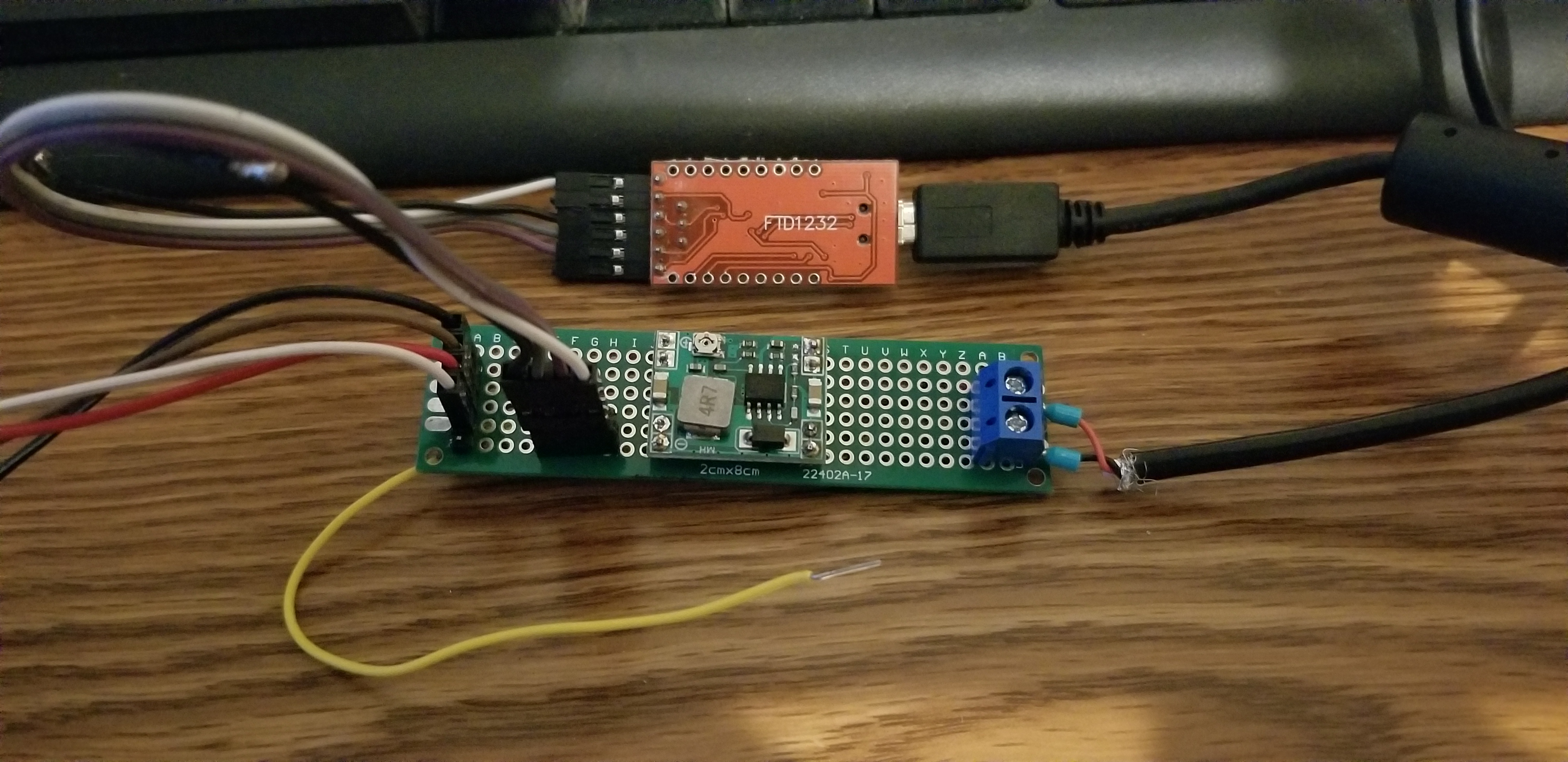
You can see the yellow wire going to nowhere. I use that to just temporarily touch to TP16 when I first plug in the Sonoff to get it into flash mode then I remove it from there when it's booted up before flashing. Then I don't have to worry about screwing up the connection with soldering.
After that you can just unplug it and plug it back in without the yellow wire touching anything to reboot it.
finity69x2
on 2 Nov 2018
@ExplodingLemur
Yep. In order to get the RF remote to re-pair with the controller I power-cycled the controller while holding a button inside the RF remote case (pop the back of the case off, hold the battery in place, and press and hold the button)
My remote has apparently decided to un-pair itself from the controller.
When you say "holding a button inside the RF remote" in your above post are you referring to the small silver button on the back side of the remote PCB?
The silver disc in the middle at the bottom side in this picture?
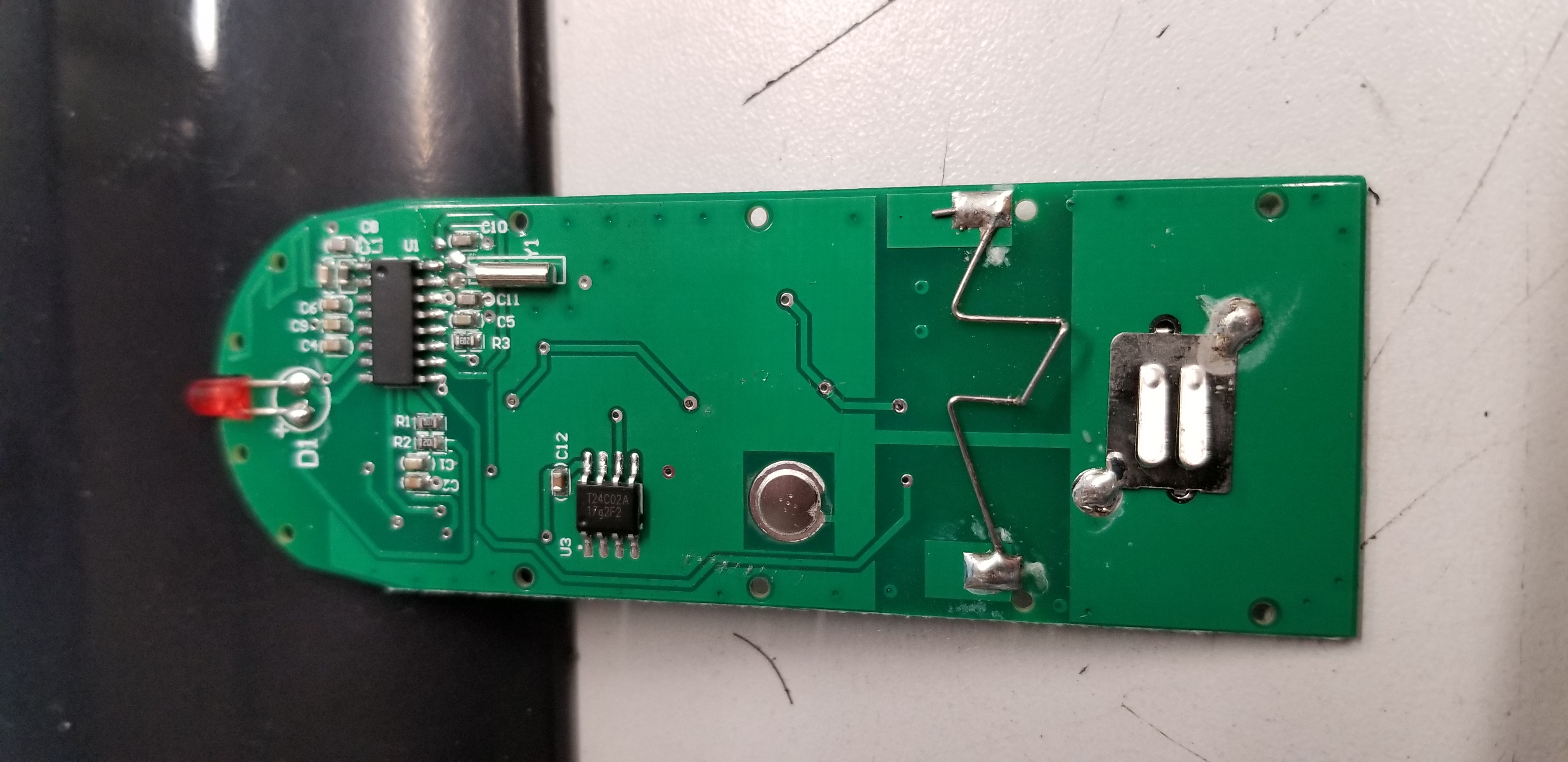
So, to clarify, I need to power cycle the controller (without holding the button on the controller itself) and only hold the button inside the remote with the battery held in the installed position until the controller reboots. And then the remote will already be paired with the controller with no other action necessary?
And you can do this with Tasmota already flashed onto the controller, correct?
finity69x2
on 11 Nov 2018
First off, a note that I'd like to mention in case this is a more widespread problem.
I purchased 2 iFan units from ITEAD. One of them had an issue where the GND connection on the serial header was NOT connected to ground. I pulled my hair out trying to figure out what I was doing wrong, and finally decided to break out the multimeter and discovered this. Not sure if I screwed it up soldering (doubtful since it looked fine) or it was a board/trace issue. Either way, I ended up soldering a pin header to the other GND connection off the SPI header and using that for the serial ground, which worked.
The second unit was just fine (I checked before and after soldering).
So, here's how I did it in case it helps others. I used a Sparkfun Beefy 3 FTDI (https://www.sparkfun.com/products/13746). The side benefit is that this FTDI board will also fully power the iFan02. I was able to get it on WiFi, get to the Web interface, MQTT... all of that without plugging into AC mains power or using a second buck converter (which I don't have handy).
To link GPIO0 and ground, I used a male/male jumper wire.
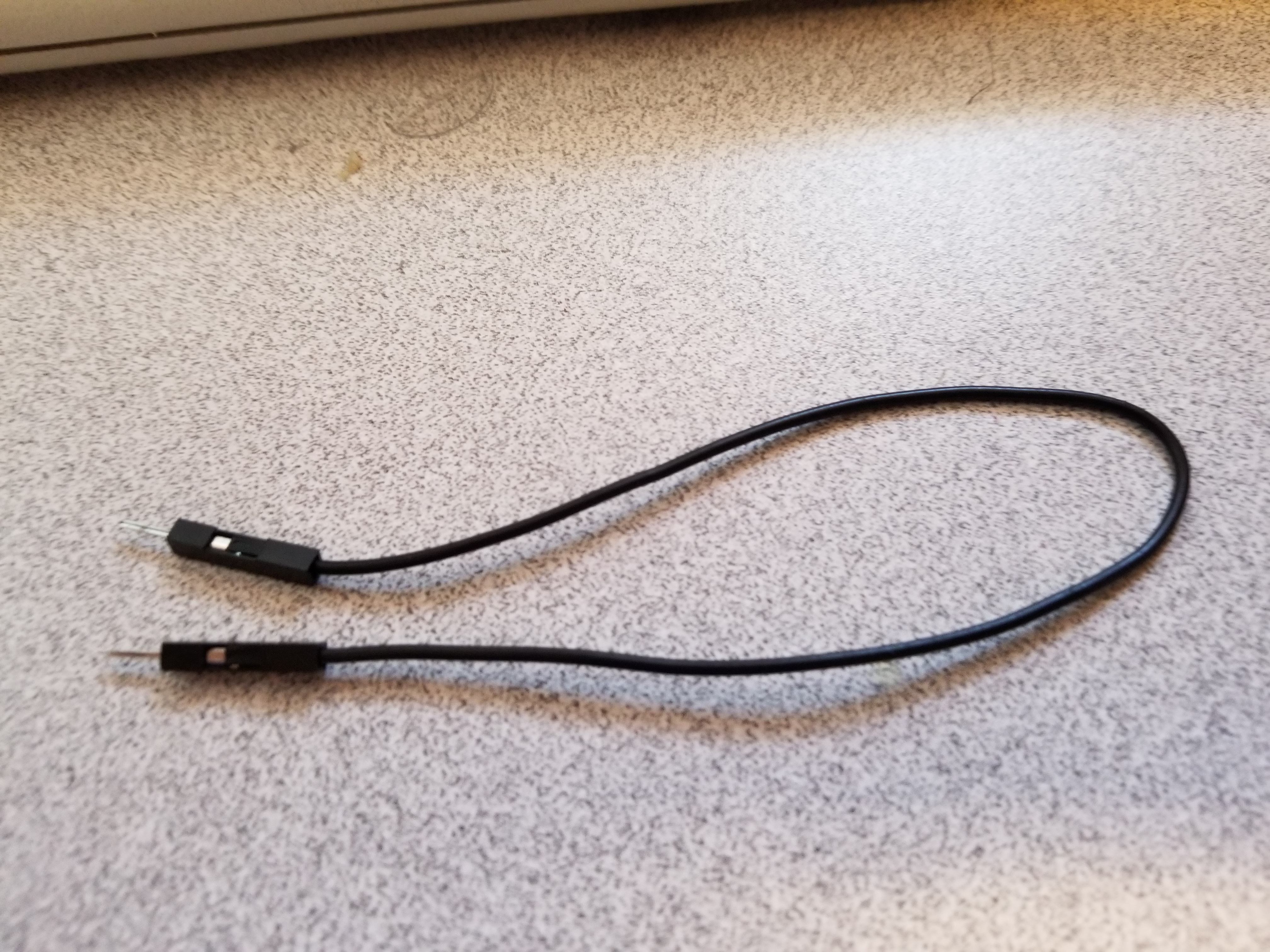
I partially plugged in the USB to the computer (no USB contact, it was just to make it easier), held the jumper wire between GND and TP16 with one hand....
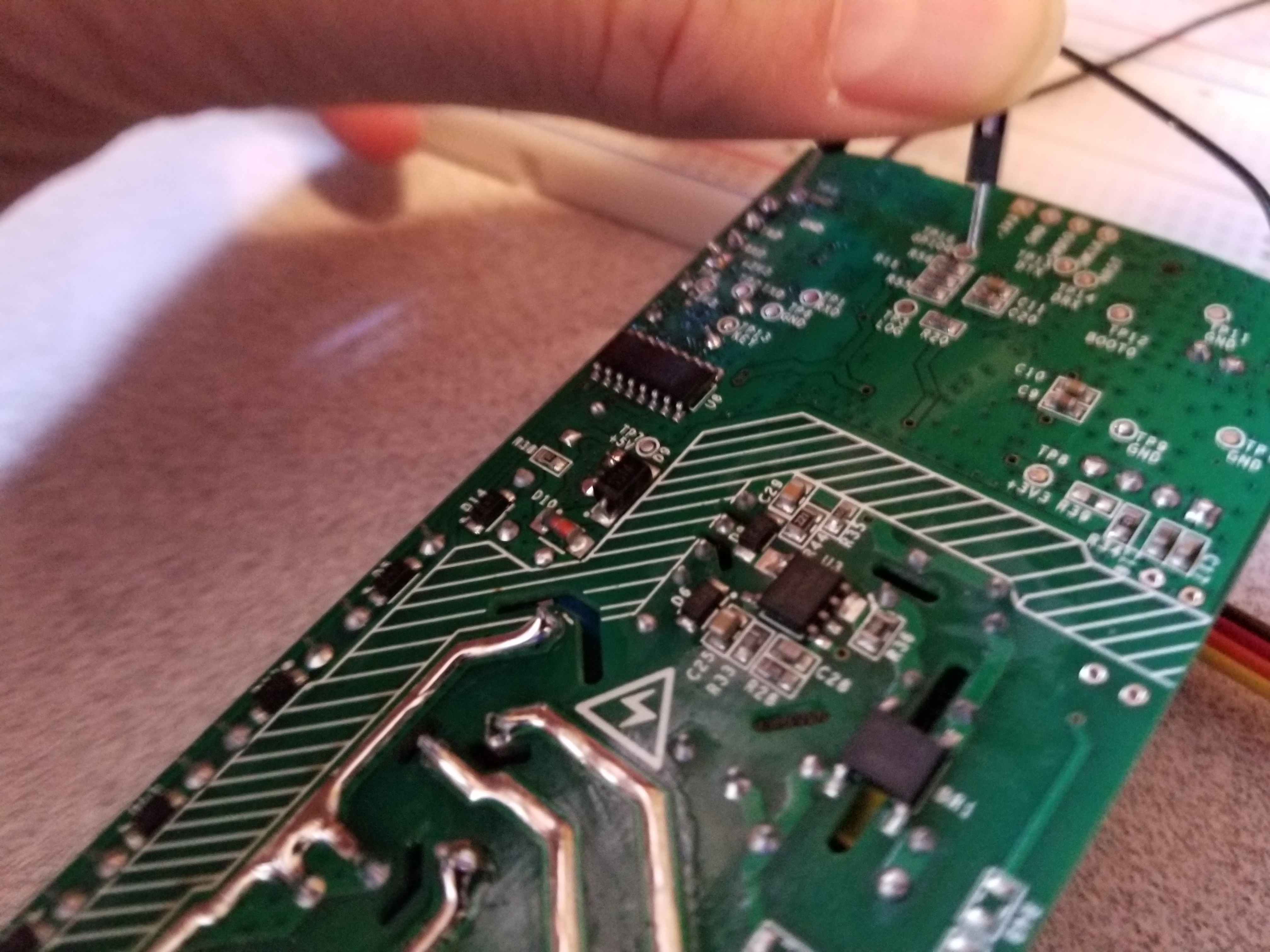
...then pushed the USB all the way into the PC with the other hand. Windows "Ba-Ding".
Go to Arduino and hit Upload. Done.
It took a few tries to get my hand coordination right, especially since I was holding the jumper wire with my left hand (and I'm horribly NOT left-handed!), but is a heck of lot easier than soldering a wire and worrying about pulling the pads off....
 mmotley999
on 11 Nov 2018
mmotley999
on 11 Nov 2018
@finity69x2
When you say "holding a button inside the RF remote" in your above post are you referring to the small silver button on the back side of the remote PCB?
The silver disc in the middle at the bottom side in this picture?
So, to clarify, I need to power cycle the controller (without holding the button on the controller itself) and only hold the button inside the remote with the battery held in the installed position until the controller reboots. And then the remote will already be paired with the controller with no other action necessary?
And you can do this with Tasmota already flashed onto the controller, correct?
Yep, that's all correct.
ExplodingLemur
on 12 Nov 2018
Am I understanding that the rule posted earlier and also on the wiki will work with a spst switch and increment the fan speed when the switch is toggled, i.e. I can connect a standard pull chain switch to it and control it like a normal fan? Related note, is there a second free gpio so I can control both fan and light this way?
 DieKatzchen
on 23 Nov 2018
DieKatzchen
on 23 Nov 2018
@DieKatzchen you can use the RX/TX pins on the header as GPIO pins just as long as you don't have GPIO1 held low at boot time during power outages and such.
What works great is a MCP23017 expander board via i2c on the RX/TX pins. Then you have 16 input/outputs at your finger tips. I showed one on my 2nd part of i2c with Tasmota on my YouTube channel. I have 3 touch buttons, 1 PIR and 7 channels of LED lights on a faceplate off the iFan02.
digiblur
on 23 Nov 2018
Thanks. I only needed one additional gpio, so I probably don't need the expander, but I'll keep it in mind. What about connecting a toggle switch and using a rule to use it to cycle through fan speeds? I can do it with a circuit, but it makes more sense to do it programmatically.
[EDIT] I'm an idiot. If I'm using a toggle and triggering on state change, it's guaranteed that about half the time gpio1 will be held low.[/EDIT]
DieKatzchen
on 23 Nov 2018
Can anyone tell me what settings should be set when using the Arudino IDE for flashing? I am using a Arduino Duemilanove with the chip removed like mentioned in the Wiki. In the general flashing instruction I see information for 8266 chips and their version but nothing about the 8285.
EDIT: I am able to flash it, but it keeps boot looping after so not sure I have everything set correctly.
 w1ll1am23
on 7 Dec 2018
w1ll1am23
on 7 Dec 2018
When I did mine, I didn’t power it with a bench supply. And I used 9600.
On Fri, Jan 4, 2019 at 11:49 PM theflu notifications@github.com wrote:
I am getting gibberish when trying to connect to the ifan2 I have my baud
set to 115200. The ifan2 is being powered by a bench power supply 3.3v. the
board is pulling .111 - .117 amps on normal boot and .078 - .081 when TP16
is put to ground.—
You are receiving this because you were mentioned.
Reply to this email directly, view it on GitHub
https://github.com/arendst/Sonoff-Tasmota/issues/2839#issuecomment-451627758,
or mute the thread
https://github.com/notifications/unsubscribe-auth/AAUrU-MZSKQ1P283-4G-U_h-JgkTPbeWks5vAC7cgaJpZM4UPDk4
.
vmarks
on 5 Jan 2019
How does connecting to alexa work with this? Does it appear as two hue bulbs, and one is dimmable?
DieKatzchen
on 30 Jan 2019
Alexa enabled are the ifan02 when you buy the product and (Evelink) Sonoff cloud app, when you flash ifan02, with tasmota the you build op you own smart home, Home Assistant fx.. then you set it by MQTT commands and through a broker (core mosquitto) fx.. But if you never flashed anything, try a few Sonoff Basic at first, and make it work.. because what I know their no going back (evelink)..
good luck ✌️
Sendt fra min iPhone
Den 30. jan. 2019 kl. 07.26 skrev DieKatzchen notifications@github.com:
How does connecting to alexa work with this? Does it appear as two hue bulbs, and one is dimmable?
—
You are receiving this because you commented.
Reply to this email directly, view it on GitHub, or mute the thread.
darkice555
on 30 Jan 2019
Sorry, didn’t answer you, no Light on/off and fan motor on/off Fanspeed: 1-2-3 and then you pay 5$ a month so Alexa can be enabled again (home assistant) 😅
Sendt fra min iPhone
Den 30. jan. 2019 kl. 07.26 skrev DieKatzchen notifications@github.com:
How does connecting to alexa work with this? Does it appear as two hue bulbs, and one is dimmable?
—
You are receiving this because you commented.
Reply to this email directly, view it on GitHub, or mute the thread.
darkice555
on 30 Jan 2019
There is going back to the original firmware, as long as you back it up
before you erase. I flashed to Tasmota, and then flashed back to original
ewelink firmware on ifan02 without problems.
On Wed, Jan 30, 2019 at 2:34 AM darkice555 notifications@github.com wrote:
Alexa enabled are the ifan02 when you buy the product and (Evelink) Sonoff
cloud app, when you flash ifan02, with tasmota the you build op you own
smart home, Home Assistant fx.. then you set it by MQTT commands and
through a broker (core mosquitto) fx.. But if you never flashed anything,
try a few Sonoff Basic at first, and make it work.. because what I know
their no going back (evelink)..
good luck ✌️Sendt fra min iPhone
Den 30. jan. 2019 kl. 07.26 skrev DieKatzchen <[email protected]
:How does connecting to alexa work with this? Does it appear as two hue
bulbs, and one is dimmable?—
You are receiving this because you commented.
Reply to this email directly, view it on GitHub, or mute the thread.—
You are receiving this because you were mentioned.
Reply to this email directly, view it on GitHub
https://github.com/arendst/Sonoff-Tasmota/issues/2839#issuecomment-458841529,
or mute the thread
https://github.com/notifications/unsubscribe-auth/AAUrUz3Gb0uJvdIGhnopKxBEVVKbP_mUks5vIUr9gaJpZM4UPDk4
.
vmarks
on 30 Jan 2019
I am planning to have wall switches for my sonoff basics by using a TTP223 as a touch pad. Can i do something for iFan02?
What I mean is what mods do i need to make on the circuits to be able to control speed, as there is only 1 button on the device that turn the light on/off. I want to be able to tunr on/off the fan and also change speed from the device directly (not using the rf remote)
 rishabmehta7
on 7 Feb 2019
rishabmehta7
on 7 Feb 2019
@rishabmehta7 I use two gang sonoff touch for light and fanspeed. just in case there is a loss of internet connectivity I use knx to send the commands. It's quite slow (the transfer protocol for knx is a very slow baud rate) but it is reliable.
jpadie
on 7 Feb 2019
@jpadie the issue with using sonoff touch for me is the touch pad are too big for standard switches used here in India!
I want to be able to connect to another GPIO pin probably and then use that with a switch to cycle through the fan speeds. Any clue on that?
I am still on stock FW and dont plan to switch to tasmota or something similar for a long time just for the lack of time i can invest in this.
Also i hav no clue what knx is so might have to read up on that.
I am actually very new to this tinkering, had done a lot of this in college but lost touch for almost 5 years now.
rishabmehta7
on 7 Feb 2019
@rishabmehta7 This thread is so long, I doubt you could find it, but there is info further up about attaching switches to the two exposed gpio pins (TX/rx). The problem you may run into is one of them cannot be held low on boot or it will not boot properly (just like gpio 0).
I took some clues from @digiblur and connected an mcp23008 gpio expander to one of those gpio’s. It uses i2c to give you 8 more binary gpio pins. It is not an easy project though.
The other side of that is, if you aren’t putting tasmota on it, you can’t do anything with those inputs anyway. The stock firmware is not configurable like that.
welbo97
on 7 Feb 2019
https://youtu.be/r-kZ3OBeRrA is the one I showed my little setup with several LEDs and buttons on my iFan02.
digiblur
on 7 Feb 2019
before i post an issue on its own, wanted to ask if anyone else's Ifan02 beeps when the SSID is not present? When i reboot the router the Ifan02 goes nuts beeping - only a hard power cycle cures it. Annoying when I upgrade the router. Any way of changing this?
 jaburges
on 15 Feb 2019
jaburges
on 15 Feb 2019
I have removed the small speaker on both of my units with a soldering iron .. did not have the same problem with what you describe, but when I cut off the power on the wall socket and switched on again, they beckoned and had to remove the sound every time with the remote control
fra min iPhone
Den 15. feb. 2019 kl. 03.06 skrev jaburges notifications@github.com:
before i post an issue on its own, wanted to ask if anyone else's Ifan02 beeps when the SSID is not present? When i reboot the router the Ifan02 goes nuts beeping - only a hard power cycle cures it. Annoying when I upgrade the router. Any way of changing this?
—
You are receiving this because you commented.
Reply to this email directly, view it on GitHub, or mute the thread.
darkice555
on 15 Feb 2019
Yes, that is a common issue. Unfortunately the arm processor controls the
beep so there’s nothing tasmota can do about it. I’ve seen it suggested
that removing the buzzer physically is the fix. Of course that leaves you
with nothing. Personally, I put a drop of hot glue on top of it. Made it
tolerable.
welbo97
on 15 Feb 2019
I am having a bit of trouble getting serial communication with the ifan02 and want to clarify some setup/wiring/procedure to establish communication with the controller.
My assumptions follow:
3.3V needs to come from a different source than the USB-RS232 interface.
To go into firmware mode, do the following:
Ground GPIO0(TP16)
plug in USB( Can this also be done by pushing the button on the ifan02? )
wait a few seconds
remove ground from GPIO0(TP16)
start espptool.py to load tasmota firmware.
Also, is the baudrate 115200 or 9600?
I have not had success yet getting a response from the serial connection or the esptool.py upload utility.
I tried the above, and also the following steps
power up the usb to rs232 interface
use jumpers to connect rx->tx, tx->rx, gnd->gnd and 3v3 from raspberry pi to 3v3 on the ifan02.
unplug 3v3 between rpi and ifan02.
ground tp16
plug in 3v3 from rpi to ifan02
after a couple seconds, remove ground from tp16
start esptool.py command to load firmware.
I see the dots and dashes, and then it times out.
Any ideas where I have gone wrong?
thanks!
 jr3us
on 6 Mar 2019
jr3us
on 6 Mar 2019
@jr3us, I did not have any issues using the 3.3v off my FTDI, just like any other Sonoff. The first one I tried was a Sparkfun Beefy, but I also tried my older/non-"beefy" FTDI and it worked as well. Maybe I just got lucky, but it's worth a try.
I bought two iFan02 units, and found that one of them had an issue with ground on the serial header.... basically, it wasn't connected to ground, which I verified with a multimeter after an hour or so of going crazy trying to flash it. It may not be your issue, but it is certainly an easy place to start troubleshooting. I ended up pulling ground off one of the other pin headers and was able to flash.
In my case, I used Arduino IDE to flash. Used the 8285 profile, and seem to recall I used 115200 baud (it's been a while since I flashed mine).
mmotley999
on 6 Mar 2019
thank you! I did note your comment regarding ground, and verified that it was tied to other ground points on the ckt board. I am also wanting to make sure my steps are in the proper order as well. Do they look correct to you?
I haven't seen anything yet on the serial port using miniterm.
Also, is the baud rate 115200 the correct baud rate when trying to get something out of it?
thanks!
jr3us
on 6 Mar 2019
@jr3us, sorry for the delay. Yes, the process seems correct. Definitely the baud rate is 115200.
The grounding of TP16 is the tricky bit, it is possible the timing is off. I didn't have to hold any button down at all to flash, just a jumper between TP16 and GND for a few seconds.
mmotley999
on 25 Mar 2019
I'm still trying to get it into firmware mode, but I am now realizing that it is still a power problem.
I have tried a 3 different power sources, as follows:
ftdi power, and no success also no buzzer.
raspberry 3v3 power pin, and no success using the ftdi only for serial and no buzzer.
Breadboard 3.3V/5V Power Supply Module for breadboards, no success and no buzzer.
I think I am going to try the 'rubber underwear' mode and wire 110v into the unit, and be very careful when handling the unit while attempting to program. I have hooked it up this way before, but never had the correct sequence of button, gpio0 ground, etc.
Thanks,
jr3us
on 9 Apr 2019
Hi, It was pretty easy to flash the Ifan2, when I had to flash mine I used flasheasy, and ardunio with 4 male Dupont in the ifan2 board, like every other Sonoff products, then I connected a female/male cable on the other side on the male pin, on ground input, and placed the male end on tp16 If I remember it right.. connected the usb from my arduino to computer, while tp16 is touched by that single cable, and then I was in flash mode.. only touched tp16, while usb where connected, and removed it again.. pressed flash on the program, and tasmota was on.. only 3,3v from my arduino and nothing else..
darkice555
on 10 Apr 2019
You can provide the needed power to your IFAN2 by wiring 2 AA batteries in series to provide the needed 3.3 volts.
Steps:
- Build battery pack by connecting 2 AA batteries in series
- Connect RX, TX, and GND on J2
- Connect GND from battery pack to J3
- Hold extra ground wire to GPIO0
- Hold down reset button
- Connect positive wire from battery pack
- Unplug and plug back in the USB TTL device so your pc recognizes it
- Lift wire from GPIO0 and release reset button
- Flash device
https://photos.google.com/u/1/photo/AF1QipN7A6BTpPZADBVaI3rC4lRIfg5ljWIWD7_cH-1l
https://photos.google.com/u/1/photo/AF1QipPO_zQl8FGeNNj9qK8OZJQWWlS0Zz01t4uJRJpc
https://photos.google.com/u/1/photo/AF1QipPGDNs8duMIsmicqwyi_slux81hcez-KsiNS-TR
 dsldsl1980
on 4 May 2019
dsldsl1980
on 4 May 2019
Itead (aliexpress and Banggood also) now have a SONOFF IFan03. Don't have one yet. Wonder if it is 8285/8266...
 Sawadee2u
on 15 Jun 2019
Sawadee2u
on 15 Jun 2019
Yes it is 8285. Appears to be the same design except with a 433mhz remote this time around.
digiblur
on 15 Jun 2019
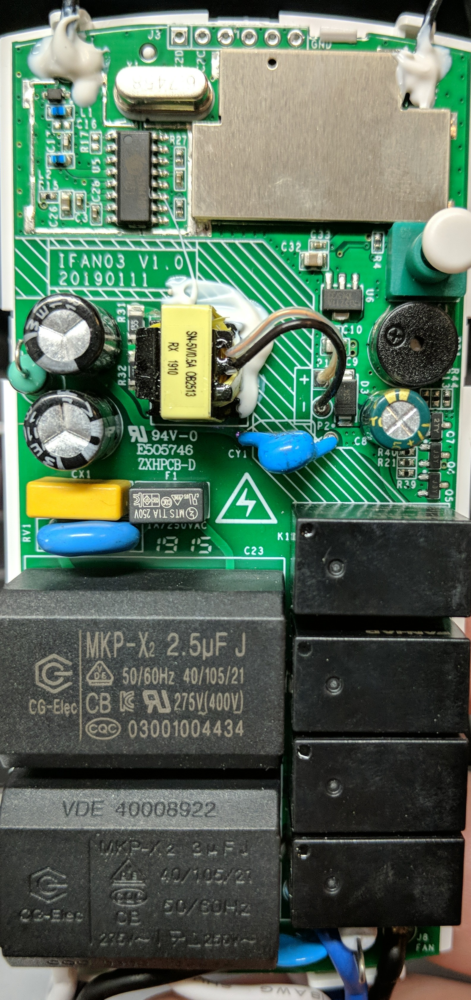
and here's the internal photos showing the ESP8285 https://fccid.io/2APN5IFAN03/Internal-Photos/Int-Photos-4294823
digiblur
on 15 Jun 2019
Thanks . Very useful. Tried to order but not available on BG or Ali yet.
Thanks again
Sawadee2u
on 15 Jun 2019
@digiblur awaiting arrival of my own ifan03, can I reasonably assume it will support tasmota?
Does anyone else have confirmation of this?
 hutchwilco
on 18 Jun 2019
hutchwilco
on 18 Jun 2019
Hi. I'm a bit of a noob to all this. I used a CH340G to flash 2 Sonoff/TH16's - no issues. Now I'm trying to flash the ifan02. I'm struggling to understand the power part, do I literally wire the ifan02 to 120v AC coming from the wall to flash this? Has anyone has written up some detailed steps just on the flashing part for the ifan02? Appreciate any advice.... thank you.
 sschnoor
on 22 Jun 2019
sschnoor
on 22 Jun 2019
I have wired it to the wall, but it’s not advisable- instead use a serial
adapter that can supply 5vdc to run it.
On Sat, Jun 22, 2019 at 5:39 PM sean notifications@github.com wrote:
Hi. I'm a bit of a noob to all this. I used a CH340G to flash 2
Sonoff/TH16's - no issues. Now I'm trying to flash the ifan02. I'm
struggling to understand the power part, do I literally wire the ifan02 to
120v AC coming from the wall to flash this? Has anyone has written up some
detailed steps just on the flashing part for the ifan02? Appreciate any
advice.... thank you.—
You are receiving this because you were mentioned.
Reply to this email directly, view it on GitHub
https://github.com/arendst/Sonoff-Tasmota/issues/2839?email_source=notifications&email_token=AACSWU6VN5VBZU32PQX2I63P32LY3A5CNFSM4FB4HE4KYY3PNVWWK3TUL52HS4DFVREXG43VMVBW63LNMVXHJKTDN5WW2ZLOORPWSZGODYKR2HY#issuecomment-504700191,
or mute the thread
https://github.com/notifications/unsubscribe-auth/AACSWU6PJLPGT676AFT2RTLP32LY3ANCNFSM4FB4HE4A
.
vmarks
on 22 Jun 2019
I know of no device that one programs with AC connected. I would not do that. Wait for someone that has done this to reply. I do not have one but will get the version 3 when it is released.
Good luck
“We do the things we have to so we can do the things we want to"
On Jun 22, 2019, at 5:39 PM, sean notifications@github.com wrote:
Hi. I'm a bit of a noob to all this. I used a CH340G to flash 2 Sonoff/TH16's - no issues. Now I'm trying to flash the ifan02. I'm struggling to understand the power part, do I literally wire the ifan02 to 120v AC coming from the wall to flash this? Has anyone has written up some detailed steps just on the flashing part for the ifan02? Appreciate any advice.... thank you.
—
You are receiving this because you commented.
Reply to this email directly, view it on GitHub, or mute the thread.
Sawadee2u
on 22 Jun 2019
Yeah - my conservative nature says connecting to AC is just wrong....will wait for someone has done this is the plan @Sawadee2u . Thanks! :)
sschnoor
on 22 Jun 2019
If flashing using the serial interface, NEVER connect the device to AC mains. The only time you can flash a device while plugged into mains is when you flash it OTA (e.g., Tuya-Convert).
 meingraham
on 23 Jun 2019
meingraham
on 23 Jun 2019
Hi. I'm a bit of a noob to all this. I used a CH340G to flash 2 Sonoff/TH16's - no issues. Now I'm trying to flash the ifan02. I'm struggling to understand the power part, do I literally wire the ifan02 to 120v AC coming from the wall to flash this? Has anyone has written up some detailed steps just on the flashing part for the ifan02? Appreciate any advice.... thank you.
@sschnoor Just to be really clear, (it's great that you knew enough to come ask first) the reason you shouldn't flash while powered up on AC is the danger - to you, and to your computer, serial interface and connected devices.
In most reputable devices, for safety reasons AC parts of the circuit maintain a minimum of "two fault" isolation from the DC or extra low voltage parts that might be accessible to a person (so that one fault of isolation will not cause an unsafe situation).
Sonoff products are not necessarily designed with this level of care in this regard as we would expect from devices compliant to common safety standards.
Since you are flashing the very low voltage areas (3V), you can power the important parts using a 3.3V DC supply onto the pad usually labelled VCC (positive or "+") and GND (negative or "-").
Your serial-USB converter may have 3V output in which case you can use that. Beware though that many do not, and instead have 5V (since that is USB standard). 5V is likely to damage a 3.3V device you are flashing. You can power it with a cheap separate power supply such as MB102-Breadboard-Module-Adapter-Shield. Just make sure you have the GND for the serial interface and power supply connected together at the iFan serial GND.
hutchwilco
on 23 Jun 2019
I would like to clairfy some things.
The ifan02 can be flash safely (if you are very careful) while powered by 120 and connected to a computer. I have 3 and did this so can confirm that it works and so do my computers.
In fact this page https://github.com/arendst/Sonoff-Tasmota/wiki/Sonoff-iFan02 hints at that and I believe use to even explain that doing so was okay because the power is isolated.
It should be noted that this isn't the case with all sonoff devices.
I guess I should mention that there are safer ways to do this mentioned in this thread and you shouldn't use the 120v method of you are 100% confident in your abilities to do so.
w1ll1am23
on 23 Jun 2019
"I'm a bit of a noob to all this" - this is the red flag that caused me to
recommend that the OP not attempt mains power to flash. But, at the end of
the day, this is "at your own risk".
On Sat, Jun 22, 2019 at 8:05 PM William Scanlon notifications@github.com
wrote:
I would like to clairfy some things.
The ifan02 can be flash safely (if you are very careful) while powered by
120 and connected to a computer. I have 3 and did this so can confirm that
it works and so do my computers.In fact this page
https://github.com/arendst/Sonoff-Tasmota/wiki/Sonoff-iFan02 hints at
that and I believe use to even explain that doing so was okay because the
power is isolated.It should be noted that this isn't the case with all sonoff devices.
—
You are receiving this because you commented.
Reply to this email directly, view it on GitHub
https://github.com/arendst/Sonoff-Tasmota/issues/2839?email_source=notifications&email_token=AIF724WVFKVJIRKPA4HYN3LP3244ZA5CNFSM4FB4HE4KYY3PNVWWK3TUL52HS4DFVREXG43VMVBW63LNMVXHJKTDN5WW2ZLOORPWSZGODYKTSVI#issuecomment-504707413,
or mute the thread
https://github.com/notifications/unsubscribe-auth/AIF724X2JWIRFFRD3GW6WQDP3244ZANCNFSM4FB4HE4A
.
meingraham
on 23 Jun 2019
@w1ll1am23 , hello. Have you written up any steps do this? I'm seeing bits and pieces of steps in the thread here, but was hoping for something more complete. And fwiw - seems my noob comment was misunderstood (but appreciate the caution from everyone ;] )- I simply meant new to flashing these types of devices. As far as working with AC/main power, I've installed sub-panels, re-wired my house, etc. Thanks!
sschnoor
on 24 Jun 2019
I highly recommend picking up something like the μArt for flashing devices like this. It has full galvanic isolation so is pretty safe to use to flash stuff connected to mains power. It doesn't protect from being an idiot and hooking it up wrong or just touching the wrong thing when connected to mains, so the safest is still what everyone keeps saying and "just don't hook it up to mains power when flashing".
I've got one and it is my go-to for flashing pretty much everything even if it isn't hooked up to mains power.
 kll
on 25 Jun 2019
kll
on 25 Jun 2019
There should be a diagram in the wiki for a power supply/flasher circuit that I created. While you could flash connected to ac why would you want to put yourself at unnecessary risk if there is a safer alternative?
finity69x2
on 27 Jun 2019
Hi all, new user from the Netherlands here. I've started using Domoticz a few months ago and progressed to Sonoff and Tasmota soon after. I've managed to flash and control quite a few Basics and a Touch T2. I'm working on controlling my ceiling fan right now using the Ifan02. I've got the hard part done, unit is flashed and installed. I've configured MQTT and Domoticz services and created two virtual switches (one for the light and one for the fanspeed). The light switch works, but I can't get the fanspeed to work. I've created a button switch with four options (off, one, two and three) but this sends the wrong MQTT messages. How do I get this to work properly? Thanks for the advice. Regards, Ward
 Bizzarrini
on 1 Jul 2019
Bizzarrini
on 1 Jul 2019
@bizzarrini can you tell me how you went about flashing your ifan02? Thank you
sschnoor
on 2 Jul 2019
@sschnoor sure, actually I just followed the instructions on this page and the Tasmota wiki. I used a serial to usb convertor to connect GND, TX and RX while I powered the Ifan02 unit from one of my NodeMCU devices attached to a powerbank. I interconnected the GND of all devices first. For flashing I used the NodeMCU firmware flashing tool.
Bizzarrini
on 2 Jul 2019
The mqtt endpoint for fan speed is cmnd/fanspeed. Is that what you are using? If not, tell us what steps you have taken to debug and share your setup to that we can better understand the issues. On 1 Jul 2019 21:51, Bizzarrini notifications@github.com wrote:Hi all, new user from the Netherlands here. I've started using Domoticz a few months ago and progressed to Sonoff and Tasmota soon after. I've managed to flash and control quite a few Basics and a Touch T2. I'm working on controlling my ceiling fan right now using the Ifan02. I've got the hard part done, unit is flashed and installed. I've configured MQTT and Domoticz services and created two virtual switches (one for the light and one for the fanspeed). The light switch works, but I can't get the fanspeed to work. I've created a button switch with four options (off, one, two and three) but this sends the wrong MQTT messages. How do I get this to work properly? Thanks for the advice. Regards, Ward
—You are receiving this because you were mentioned.Reply to this email directly, view it on GitHub, or mute the thread.
jpadie
on 2 Jul 2019
Thanks for your reply. In the Tasmota settings it's possible to define an MQTT server, which I've also added to Domoticz. I've created two virtual switches in Domoticz. In the Tasmota interface it's possible to enter the switch ID'S so tasmota can communicate with Domoticz through the pre defined MQTT server. This way I can switch the light (as I've also accomplished with a few Sonoff Basics), however the commands originating from the Domoticz fan switch don't match the expected input to Tasmota.
Bizzarrini
on 2 Jul 2019
So it sounds like domoticz is just sending an on/off command to power2 Which won't always work when tasmota is expecting a numerical message sent to fanspeed. Are you convinced that domoticz is flexible enough to support your use case?On 2 Jul 2019 10:24, Bizzarrini notifications@github.com wrote:Thanks for your reply. In the Tasmota settings it's possible to define an MQTT server, which I've also added to Domoticz. I've created two virtual switches in Domoticz. In the Tasmota interface it's possible to enter the switch ID'S so tasmota can communicate with Domoticz through the pre defined MQTT server. This way I can switch the light (as I've also accomplished with a few Sonoff Basics), however the commands originating from the Domoticz fan switch don't match the expected input to Tasmota.
—You are receiving this because you were mentioned.Reply to this email directly, view it on GitHub, or mute the thread.
jpadie
on 2 Jul 2019
Thanks for the quick response! I'm quite new to Domoticz and especially MQTT so I'm unsure, however as Tasmota integrated the options to include two switch ID's I assumed it was possible without much hassle. I guess the other option would be to use a script to assign the correct MQTT messages to the switch positions, but that's something I have zero experience with unfortunately. I'll look into this option.
Bizzarrini
on 2 Jul 2019
I don't use domoticz at all. Are you able to specify arbitrary topics and payloads?If so use cmdn/fanspeed as the end of your topic and + as the payload. Try to get that working and move on from there. It will cycle between fan speeds. Alternatively I have written a script and web page to control the ifan. Runs on Linux. Best used if you can access the web page externally. On 2 Jul 2019 10:32, Bizzarrini notifications@github.com wrote:Thanks for the quick response! I'm quite new to Domoticz and especially MQTT so I'm unsure, however as Tasmota integrated the options to include two switch ID's I assumed it was possible without much hassle. I guess the other option would be to use a script to assign the correct MQTT messages to the switch positions, but that's something I have zero experience with unfortunately. I'll look into this option.
—You are receiving this because you were mentioned.Reply to this email directly, view it on GitHub, or mute the thread.
jpadie
on 2 Jul 2019
Ok for unknown reason it's working now. I checked the ingoing mqtt messages to Domoticz when I changed fanspeed from the Tasmota web interface, and they read like
{"idx":133,"nvalue":2,"svalue":"10","Battery":48,"RSSI":3},
where the svalue is 0 for off, 10 for speed 1 etc.
I then created a selector switch in Domoticz with levels 0, 10, 20 and 30 and named them off, 1, 2 and 3.
Outgoing message now looks like
{
"Battery" : 48,
"LevelActions" : "|||",
"LevelNames" : "Off|1|2|3",
"LevelOffHidden" : "undefined",
"RSSI" : 4,
"SelectorStyle" : "0",
"description" : "",
"dtype" : "Light/Switch",
"id" : "000140D5",
"idx" : 133,
"name" : "Slaapkamer Ventilator",
"nvalue" : 2,
"stype" : "Switch",
"svalue1" : "20",
"switchType" : "Selector",
"unit" : 1
}
Works like a charm now. Thanks for all the advice!
Ps: any ideas on how to change the battery level output in the message to 255 coming from Tasmota?
Bizzarrini
on 3 Jul 2019
Ok for unknown reason it's working now. I checked the ingoing mqtt messages to Domoticz when I changed fanspeed from the Tasmota web interface, and they read like
{"idx":133,"nvalue":2,"svalue":"10","Battery":48,"RSSI":3},
where the svalue is 0 for off, 10 for speed 1 etc.I then created a selector switch in Domoticz with levels 0, 10, 20 and 30 and named them off, 1, 2 and 3.
Outgoing message now looks like
{
"Battery" : 48,
"LevelActions" : "|||",
"LevelNames" : "Off|1|2|3",
"LevelOffHidden" : "undefined",
"RSSI" : 4,
"SelectorStyle" : "0",
"description" : "",
"dtype" : "Light/Switch",
"id" : "000140D5",
"idx" : 133,
"name" : "Slaapkamer Ventilator",
"nvalue" : 2,
"stype" : "Switch",
"svalue1" : "20",
"switchType" : "Selector",
"unit" : 1
}Works like a charm now. Thanks for all the advice!
Ps: any ideas on how to change the battery level output in the message to 255 coming from Tasmota?
possible to see a screenshot of your fan02?
 psnlk
on 14 Dec 2019
psnlk
on 14 Dec 2019
Hi, we are a team that needs your feedback to complete our idea.
Please visit our pages and comment on it.
github
gitlab
 nimamoslemy
on 1 May 2020
nimamoslemy
on 1 May 2020
Hello all,
I'm very amateur when it comes to electronics but, I got an iFan02 for a US ceiling fan and I'm having the same issues as reported by others above where the fan rotates extremely-slow, slow and not-so-slow-but-quite-fast.
The capacitor on my fan only has 3 wires:

Here's the diagram of the wiring for my fan:

How can I make iFan02 to work properly here? I'm not opposed to solder the iFan's capacitors out and put something else there, I just need help to know what that something else is and how the fan wiring should look like.
I do have a few 5uF capacitors but I'm not sure if I should use those on the iFan02 since that's not what the fan itself uses.
TIA
 jrfernandes
on 5 Jun 2020
jrfernandes
on 5 Jun 2020
Use the pull chord to put the fan on maximum speed and then install the ifan. Don't use the pull chord againIf somehow you do pull the chord then put the ifan on maximum speed and then pull the chord sequentially until the fan spins more or less at top speed. On 5 Jun 2020 23:07, Joel Fernandes notifications@github.com wrote:
Hello all,
I'm very amateur when it comes to electronics but, I got an iFan02 for a US ceiling fan and I'm having the same issues as reported by others above where the fan rotates extremely-slow, slow and not-so-slow-but-quite-fast.
The capacitor on my fan only has 3 wires:
Here's the diagram of the wiring for my fan:
How can I make iFan02 to work properly here? I'm not opposed to solder the iFan's capacitors out and put something else there, I just need help to know what that something else is and how the fan wiring should look like.
TIA
—You are receiving this because you were mentioned.Reply to this email directly, view it on GitHub, or unsubscribe.
jpadie
on 6 Jun 2020
I had it in the position of full speed. I'm not sure if it was before installing the iFan or if I did that after. Does that really make a difference?
jrfernandes
on 6 Jun 2020
No. It doesn't make a difference other than being easier to determine. Do you have a tool to measure the capacitances?On 6 Jun 2020 01:18, Joel Fernandes notifications@github.com wrote:
I had it in the position of full speed. I'm not sure if it was before installing the iFan or if I did that after. Does that really make a difference?
—You are receiving this because you were mentioned.Reply to this email directly, view it on GitHub, or unsubscribe.
jpadie
on 6 Jun 2020
@Joel
I’ve been thinking about this quite a bit today as I have a current project to build an improved version of the iFan for my fans (mostly I don’t like the form factor of the iFan as it does not fit the kind of fans I have got). From what I read online whilst the majority of fans are split capacitor variants, some have permanently wired start capacitors and windings. Another variation is that some have rotary switches that pass the current through to the motor directly in fan speed 3 and then via the capacitor legs in fan speeds 1 and 2, whereas others will pass the current through to one leg, then the other and then both for speed control (the higher the capacitance the higher the effective speed).
In the standard ifan02 configuration of two caps (2.5uF and 3uF) my calculations show that the resultant speeds for you should be very close to your current settings (if the pull-chord is at max speed). At slow speed the resultant capacitance would be 1.54uF, (versus your 1.5uF) and at medium it is 2.32uF (versus your 2.5uF). But since you are reporting that the slow and medium speeds are very different something else may be afoot.
However … you are reporting that the slow value is in fact ‘extremely slow’ which means that there must be more capacitance being introduced somewhere. If you’re certain that this is not just observer bias, then I’d recommend testing by putting the module into generic mode (18) and setting the following
Then select relays 2 to 4 in whatever combination you want and make a note of what feels best to you in terms of slow, medium and fast fan speeds (remembering that the iFan2 ’standards’ are as above.
Armed with what you feel is best, the code can be altered to suit you. However - just as a warning - I’m not sure if this will override the remote control fan speed setting as that may not be handled by the ESP826x processor but it would at least give you control via physical buttons and mqtt/web interfaces.
If nothing seems to be adequate then there is a soldering solution too. It will also involve a custom build of tasmota (if you want to use the fanSpeed commands); and this would mean that all subsequent upgrades would need to be manually compiled. The change is only a couple of lines however.
On 6 Jun 2020, at 08:58, [email protected] wrote:
No. It doesn't make a difference other than being easier to determine.
Do you have a tool to measure the capacitances?
On 6 Jun 2020 01:18, Joel Fernandes notifications@github.com wrote:
I had it in the position of full speed. I'm not sure if it was before installing the iFan or if I did that after. Does that really make a difference?
—
You are receiving this because you were mentioned.
Reply to this email directly, view it on GitHub https://github.com/arendst/Tasmota/issues/2839#issuecomment-639889130, or unsubscribe https://github.com/notifications/unsubscribe-auth/AF7AJALLKLATDQLP4IIMERLRVF4M3ANCNFSM4FB4HE4A.No. It doesn't make a difference other than being easier to determine.
Do you have a tool to measure the capacitances?
On 6 Jun 2020 01:18, Joel Fernandes notifications@github.com wrote:
I had it in the position of full speed. I'm not sure if it was before installing the iFan or if I did that after. Does that really make a difference?
—
You are receiving this because you were mentioned.
Reply to this email directly, view it on GitHub, or unsubscribe.
jpadie
on 6 Jun 2020
I don’t. fwiw, I did have the fan speed set to maximum when having the ifan connected.
Can’t I remove the capacitor from the fan and have Iran’s capacitors to handle the speed?
jrfernandes
on 6 Jun 2020
hmm. i see that the images in my earlier post got stripped. to recap the image textually:
set GPIO4 to relay3, GPIO5 to relay2, gpio12 to relay1 and gpio 15 to relay4.
I would not do as you suggest as you are then passing full mains to your motor’s coils. It will _probably_ not start at all as there would be no phase angle for the starting coils. But you could maybe work around that by starting at a lower speed and then going to full speed. and the coils may not be able to accept that voltage resulting in a burn out or the fan spinning inappropriately fast for the bearings.
if you did want to try that route and not use the pass through relay, then you would not be able to match all three speeds as the capacitor values available to you are only 2.5uF, 3uF and 5.5uF. the fast speed would be (potentially) too fast for your fan (which is tuned to a 4uF capacitance most likely) and the slowest speed would be equivalent to your current medium speed. You again run the risk of damage, although more likely to be damage to the bearings. and you would again need a specially compiled binary.
jpadie
on 6 Jun 2020
I modified my ifan02 with the dual cap out of my 110vac fan (US). I think
there’s some pics up further from way back. IIRC the cap values were 4uf
and 8uf. The stock caps yielded the speeds: full, about what low was,
barely rotating.
I’ve seen comments that the ifan02 caps were built for 220v fans.
Frankly I’m about to pull it out and replace with a single relay
automation. Having speed control just isn’t that important to me.
welbo
On Sat, Jun 6, 2020 at 10:11 jpadie notifications@github.com wrote:
hmm. i see that the images in my earlier post got stripped. to recap the
image textually:set GPIO4 to relay3, GPIO5 to relay2, gpio12 to relay1 and gpio 15 to
relay4.I would not do as you suggest as you are then passing full mains to your
motor’s coils. It will probably not start at all as there would be no
phase angle for the starting coils. But you could maybe work around that by
starting at a lower speed and then going to full speed. and the coils may
not be able to accept that voltage resulting in a burn out or the fan
spinning inappropriately fast for the bearings.if you did want to try that route and not use the pass through relay,
then you would not be able to match all three speeds as the capacitor
values available to you are only 2.5uF, 3uF and 5.5uF. the fast speed would
be (potentially) too fast for your fan (which is tuned to a 4uF capacitance
most likely) and the slowest speed would be equivalent to your current
medium speed. You again run the risk of damage, although more likely to be
damage to the bearings. and you would again need a specially compiled
binary.—
You are receiving this because you were mentioned.
Reply to this email directly, view it on GitHub
https://github.com/arendst/Tasmota/issues/2839#issuecomment-640075807,
or unsubscribe
https://github.com/notifications/unsubscribe-auth/AEKDLQJMPAVKF6ZNKKB4YZTRVJMCZANCNFSM4FB4HE4A
.>
Thank you,
Will
979-492-5484 cell
welbo97
on 6 Jun 2020
Related issues
 wirelesssolution
·
3Comments
wirelesssolution
·
3Comments
 garret
·
3Comments
garret
·
3Comments
 he-so
·
3Comments
he-so
·
3Comments
 jensuffhaus
·
3Comments
jensuffhaus
·
3Comments
 j4k3
·
3Comments
j4k3
·
3Comments
Most helpful comment
Release of Sonoff iFan02 in Tasmota.