Tasmota: External button on the Pow R2 - PLEASE DON'T
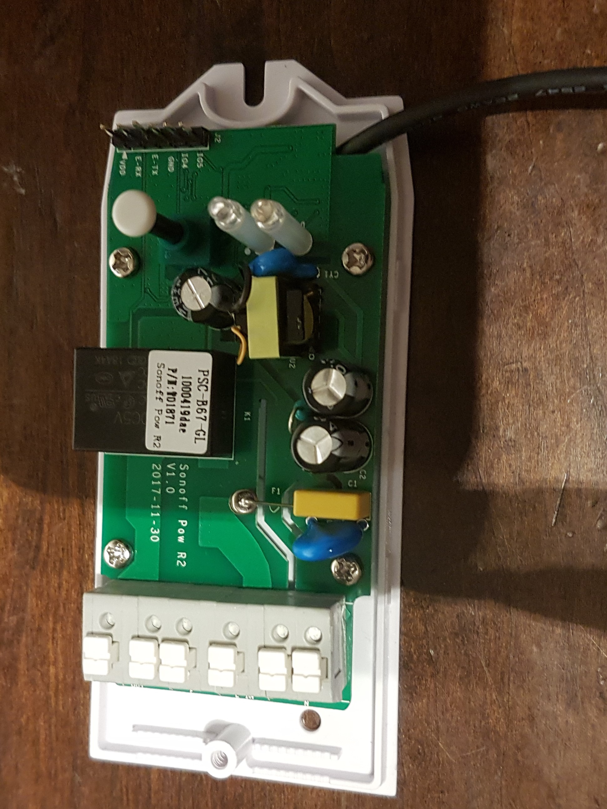
So, I got my pow R2 working after some fiddling. Yeah, we now have Sonoff ready to switch the espresso machine!
What if I want to hook up an external button to switch on/off? I can't seem to find the options in the Pow R2 settings.... It has a I04 & I05 pin... But I have no clue what those do...
Worst case... can I solder and external switch to the pins of the onboard switch?
thank you all!
 DaafSamson
All 18 comments
from the wiki
https://github.com/arendst/Sonoff-Tasmota/wiki/Sonoff-Pow-and-Pow-R2
do not use IO4 and IO5
But, you should be able to solder an external pushbutton switch to the onboard one.
 Frogmore42
on 6 May 2018
Frogmore42
on 6 May 2018
TL;DR:
_Do not solder an external button to the onboard one, live AC will be supplied to your button!_
So...
I went for the soldering option, and had some very bad results. Perhaps someone with more knowledge or better skills will make this work safely, for now I would very much advise against soldering an external button to the onboard button:
1) I soldered small leads to existing buttons pins on the underside of the PCB.
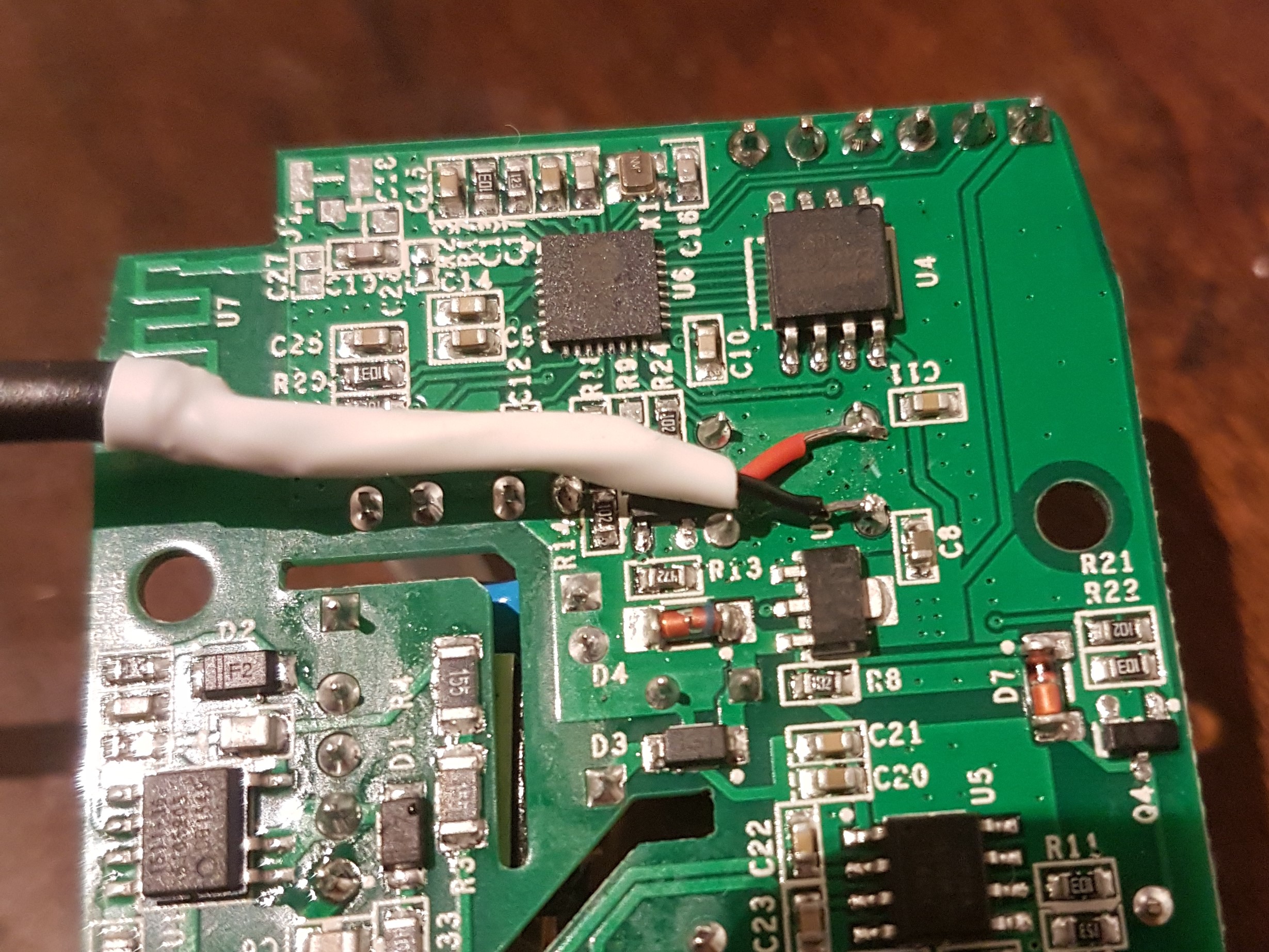
2) run the wire behind the pcb and out through the sensor hole on the left side.
3) all looks well and switching with an external switch works.
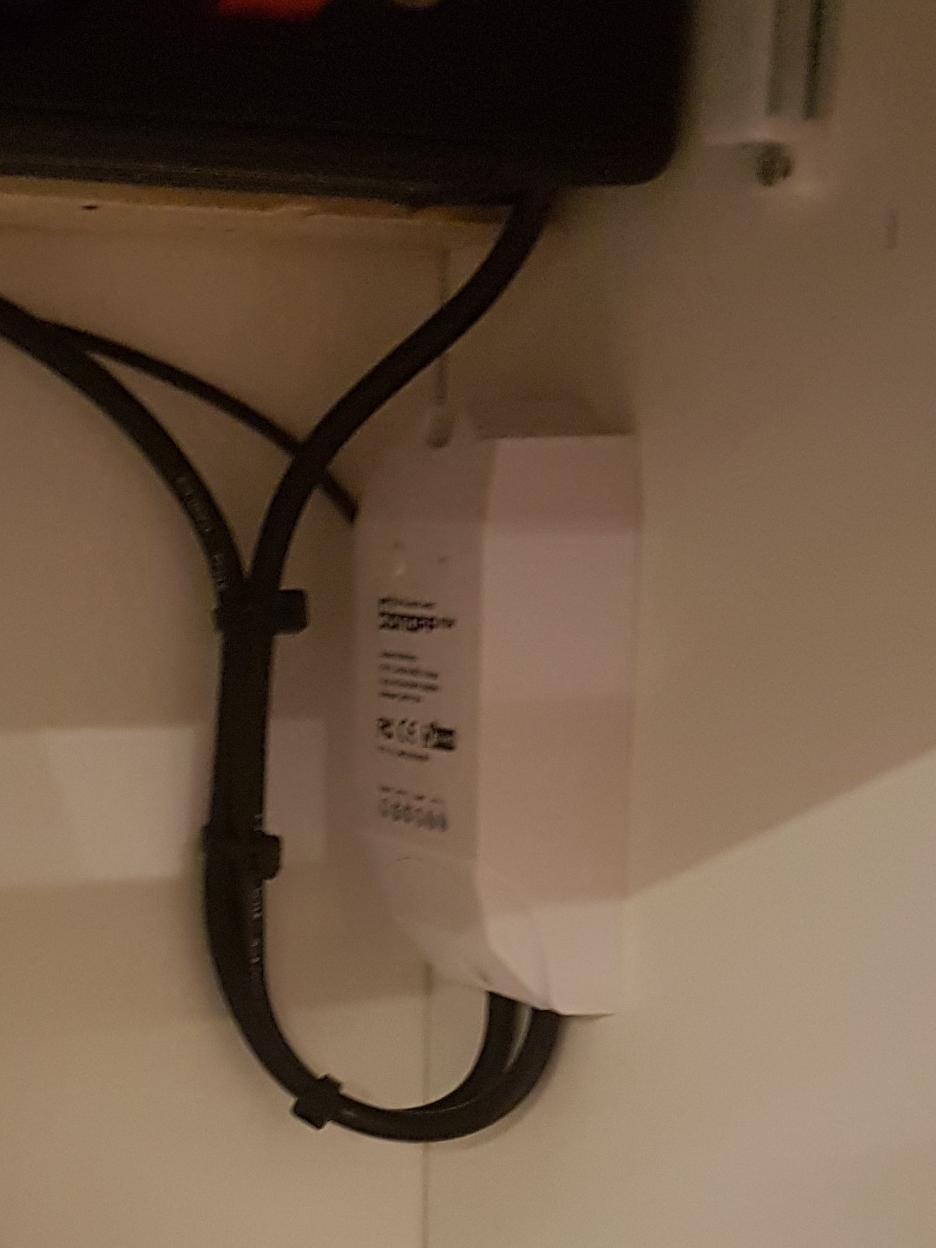
And then I think I accidentally touched the grounded housing of my espresso machine with the exposed
pins in the rear of my external switch:

The circuit breakers blew, nothing caught fire, but this gave me a small scare.
I guess that GND on the board hit that 50% chance of being connected to the live AC current as per the wiki:
⚠️️Special Pow Attention ⚠️️
Do not connect AC power and the serial connection at the same time The Gnd connection of the Pow has a 50% chance of being connected to the live AC wire. Connecting serial with your PC will fry your PC.
Also do not connect any additional sensors to serial pins until you are 100% sure. It can at least destroy your Pow!
The GPIOs on the Pow might be connected to AC power, therefore it is not possible to add sensors to the Pow.
So, be wise about this, it is probably a bad idea to try to do this my way. Perhaps when using AC grade wiring and switch you could do this, but for me... I'm going to see if there is a different Sonoff product that supports 16amps and an external switch.. perhaps a TH16?
DaafSamson
on 7 May 2018
Adding a parallel switch to the existing one is not a problem with POW. You just need to keep in mind that the wires might be on AC level, so use proper cables, switches and isolation, and you should be fine.
If you are unsure about anything you are doing with AC power: don't do it.
 tobox
on 7 May 2018
tobox
on 7 May 2018
While you CAN use a switch with the POW (of any variety), you generally should not. All the wires would have high voltage on them. There are ways to make this safe, but most people don't have the knowledge to do it correctly. It would be fine till it wasn't and then it could be life threatening. It might be yours, or it might be that of a loved one, or it might be someone else. Do you really want to take the chance?
Instead, get a wemos D1 and connect a switch and configure it to control the POW. That is much safer and a small price to pay to not lose a loved one.
Frogmore42
on 7 May 2018
Thank you all! I ordered a TH16... I'll consider playing with a wemos, but the premiss for installation at the moment is that everything should also still work if the network is down....
DaafSamson
on 7 May 2018
People have had issues with Tasmota not working as they expect when the network is not present. It is possible to configure things so that basic functionality still works from what I have heard. Normally, Tasmota will reboot if it can't connect to the network or MQTT broker.
Frogmore42
on 8 May 2018
Pall..
I have just received my sonoff Pow R2 (same build date as your board.). I'm having an issue flashing this device with the Tasmota f/w. I have flashed and programmed a number of Sonoff basic units (hold button down apply power, release and flash) and have had no issues.
I assume gpio0 is controlled by the on board push button like the Sonoff basic? and the flashing procedure should be the same! Or am I missing something. I have read the forum and have tried external 3.3v power supply etc but no success in flashing.
Any advice would be most welcome....

 dmurphydrtc
on 23 May 2018
dmurphydrtc
on 23 May 2018
Use the search feature and see the literally tens or hundreds of others who have gone before you and had their issues resolved. It is unlikely you have a new issue, but if after all of that you have not been able to figure it out.
Start a new issue. Provide more information about what you are using and what you are seeing.
Frogmore42
on 24 May 2018
dmurphydrtc,
_(noob alert) I am John Snow when it comes to these sonoffs, I know nothing. I've wrecked two (this one and a S20.) and now have a dual r2 and a TH16 working. Everything beyond this point is what little I think I picked up..._
What helped for me was, check, check, check again all your settings.
This wiki article describes them well:
https://github.com/arendst/Sonoff-Tasmota/wiki/Arduino-IDE
Half way in is the list of settings you should have in your IDE. Check those again, and again...
As for putting it in to flash mode. As far as I know, you do this by pressing the button whilst powering the sonoff. be on the safe side and keep the button pressen for atleast 10 seconds. I can't remember, but I think no lights should flash anymore.
Also. I've noticed that you can't trust RX-TX pin out labeling.
1) test GND & VCC by only connecting those to the GND and 3.3V on your FTDI adapter, the sonoff should get power and lights should start blinking. if not, probably a power issue.
2) try with RX-TX TX-RX connected cross wise (as it should be), if that doesn't work try a few times more, pray while doing it.
3) Try with RX-RX TX-TX. I can't remember which device it was, but the labeling on the sonoff seemed switched on one of mine.
Also, I noticed that my FTDI adapter did not work well, I then used a Arduino as FTDI and presto! (see this video: https://www.youtube.com/watch?v=qqSLwK1DP8Q
Other than this, read the wiki, search the forum, or start a thread with more info on your issue!
Good luck!
DaafSamson
on 24 May 2018
Hi, i solved the problem flashing new pow r2 with cse measurement ic. Seems the cse is connected to serial esp. Could be the cause... A pull up of about 500ohms on Rx pin made flashing possible on my board. Have fun!
 Cartman18
on 7 Aug 2018
Cartman18
on 7 Aug 2018
Hello
I'm interested in why IO4 and IO5 external switches can not be connected. Is it just a security problem or something else?
 teraamper
on 5 Dec 2018
teraamper
on 5 Dec 2018
POW is very dangerous to use anything else from what it is designed for. All the electronics is grounded to AC, so touching the 3.3v rail in the POW board will electrocute you since it is already connected and NOT ISOLATED to MAINS AC.
DO NOT CONNECT SWITCHES OR SENSORS TO A POW or any power measurement capable device.
It is dangerous. Use another device for switches and sensors like a nodemcu. Use a POW only por power measurement.
It is not worth to risk yourself, your family and your home for saving just very little money and not using a safe device for sensors and switches. REMEMBER, using a POW for SWITCHES OR SENSORS WILL ELECTROCUTE YOU. You will not have any support from us to do this type of modifications.
 ascillato
on 5 Dec 2018
ascillato
on 5 Dec 2018
I know that it is dangerous, but I am an electrician and professionally servicer of UPS devices. So I know what I'm doing about high voltage.
teraamper
on 5 Dec 2018
If you know what you are doing, then you should have no problem changing the code to enable what you want.
But seriously, I will work on a live power panel, but choose to not hook up anything extra to my POW. And while I do have some sensors hooked up to some TH10/16 devices, I find it easier/better to use NodeMCU type devices for sensors.
The small savings in hardware and power cost is really not worth the risk.
Frogmore42
on 5 Dec 2018
ok thanx for the help
teraamper
on 5 Dec 2018
This issue is currently a top Google result when searching for ways to connect an external switch to a POW. To add my experience, I just fitted the POW inside an existing void within a dehumidifier housing so it was not accessible at all. I really needed to expose the switch externally to allow operation in case WiFi failed.
I got a 240v momentary switch (normally open) and fitted it to the appliance housing, soldering the wires to the back of the POW board just like @DaafSamson. I was originally going to use a 240v latching switch in parallel with the POW (to bypass it completely) but I thought if I was going to do that, may as well try to switch the (possibly 240v) POW directly.
In my use case, I can tell the appliance needs attention if the Sonoff switch is on but power is zero (bucket needs emptied, stopping the dehumidifier motor).
My solder skills are weak, so this was a challenge for me. It would be nice if the POW was produced in a variant with an external switch breakout (and suitable warnings).
 Dave-McCraw
on 21 Oct 2020
Dave-McCraw
on 21 Oct 2020
POW is very dangerous to use anything else from what it is designed for. All the electronics is grounded to AC, so touching the 3.3v rail in the POW board will electrocute you since it is already connected and NOT ISOLATED to MAINS AC.
DO NOT CONNECT SWITCHES OR SENSORS TO A POW or any power measurement capable device.
It is dangerous. Use another device for switches and sensors like a nodemcu. Use a POW only por power measurement.
It is not worth to risk yourself, your family and your home for saving just very little money and not using a safe device for sensors and switches. REMEMBER, using a POW for SWITCHES OR SENSORS WILL ELECTROCUTE YOU. You will not have any support from us to do this type of modifications.
ascillato
on 21 Oct 2020
You will not have any support from us to do this type of dangerous modifications.
 ascillato2
on 21 Oct 2020
ascillato2
on 21 Oct 2020
Related issues
 ximonline
·
3Comments
ximonline
·
3Comments
 TylerDurden23
·
3Comments
TylerDurden23
·
3Comments
 j4k3
·
3Comments
j4k3
·
3Comments
 grizewald
·
3Comments
grizewald
·
3Comments
 smadds
·
3Comments
smadds
·
3Comments
Most helpful comment
Hi, i solved the problem flashing new pow r2 with cse measurement ic. Seems the cse is connected to serial esp. Could be the cause... A pull up of about 500ohms on Rx pin made flashing possible on my board. Have fun!