Checking to see if any display support is planned for the future?
I see great value in using OLED displays for non SONOFF devices, like WEMOS.
 rlust
rlust
All 89 comments
Should be possible with LiquidCrystal I2C but this lib needs space....
https://github.com/marcoschwartz/LiquidCrystal_I2C
or for OLED
https://github.com/adafruit/Adafruit_SSD1306
 Jason2866
on 27 Apr 2018
Jason2866
on 27 Apr 2018
I have some display support running for over a year but it is very user unfriendly as it only allows displaying of MQTT messages without user intervention. Displays supported are LCD, Oled, TFT and up to 8 matrices. AT home they run fine.
I might release a branch without support just for you to see what is possible.
 arendst
on 28 Apr 2018
arendst
on 28 Apr 2018
See https://github.com/arendst/Sonoff-Tasmota/tree/development_display
This is with NO support.
arendst
on 28 Apr 2018
Got it loaded, not sure how to set options?
I will continue reading code.
I am using a I2C OLED display.
Anyone have any luck here?
rlust
on 30 Apr 2018
Hello @rlust,
i am in the same boat. Got it running. Display shows Time and Date after boot.
@arendst could you give me/us just one short example, i am not a programmer so reading code isnt easy for me. But when i get a hint i get things sorted ;-) For testing i have connected a DS18B20 (Temperature is shown on Web Console)
Thx a lot, if you do not, it is 100% fine!! You said NO support ;-)
P.S.
And thank you again for your great pice of software!! With this my long wanted plan realizing
a powerful and inexpensive smart home solution (without a cloud) was made possible.
Jason2866
on 30 Apr 2018
Currently all displays have the possibility to show life MQTT messages. This probably only works when the default prefixes are used. The display driver receives all tele messages and decodes the JSON text and should display information like

Settings:
14:39:16 CMD: displaymodel
14:39:16 MQT: stat/wemos9/RESULT = {"DisplayModel":2}
14:39:20 CMD: displaymode
14:39:20 MQT: stat/wemos9/RESULT = {"DisplayMode":5}
14:39:33 CMD: displayrefresh
14:39:33 MQT: stat/wemos9/RESULT = {"DisplayRefresh":2}
14:39:45 CMD: power
14:39:45 MQT: stat/wemos9/RESULT = {"POWER":"ON"}
14:39:45 MQT: stat/wemos9/POWER = ON
14:39:56 CMD: displayrows
14:39:56 MQT: stat/wemos9/RESULT = {"DisplayRows":8}
14:40:01 CMD: displaycols
14:40:01 MQT: stat/wemos9/RESULT = {"DisplayCols1":21}

Settings:
15:41:23 CMD: displaymodel
15:41:23 MQT: stat/ticker/RESULT = {"DisplayModel":3}
15:41:28 CMD: displaymode
15:41:28 MQT: stat/ticker/RESULT = {"DisplayMode":5}
15:41:34 CMD: displayrefresh
15:41:34 MQT: stat/ticker/RESULT = {"DisplayRefresh":1}
15:41:38 CMD: power
15:41:38 MQT: stat/ticker/RESULT = {"POWER":"ON"}
15:41:38 MQT: stat/ticker/POWER = ON
15:41:49 CMD: displayrows
15:41:49 MQT: stat/ticker/RESULT = {"DisplayRows":2}
15:41:54 CMD: displaycols
15:41:54 MQT: stat/ticker/RESULT = {"DisplayCols1":32}

Settings:
15:42:46 CMD: displaymodel
15:42:46 MQT: stat/lcd/RESULT = {"DisplayModel":1}
15:42:50 CMD: displaymode
15:42:50 MQT: stat/lcd/RESULT = {"DisplayMode":4}
15:42:58 CMD: displayrefresh
15:42:58 MQT: stat/lcd/RESULT = {"DisplayRefresh":2}
15:43:01 CMD: power
15:43:01 MQT: stat/lcd/RESULT = {"POWER":"ON"}
15:43:01 MQT: stat/lcd/POWER = ON
15:43:07 CMD: displayrows
15:43:07 MQT: stat/lcd/RESULT = {"DisplayRows":2}
15:43:11 CMD: displaycols
15:43:11 MQT: stat/lcd/RESULT = {"DisplayCols1":16}
15:43:24 CMD: displayaddress
15:43:24 MQT: stat/lcd/RESULT = {"DisplayAddress1":39}

Settings:
15:44:10 CMD: displaymodel
15:44:10 MQT: stat/tft/RESULT = {"DisplayModel":4}
15:44:14 CMD: displaymode
15:44:14 MQT: stat/tft/RESULT = {"DisplayMode":5}
15:44:21 CMD: displayrefresh
15:44:21 MQT: stat/tft/RESULT = {"DisplayRefresh":2}
15:44:24 CMD: power
15:44:24 MQT: stat/tft/RESULT = {"POWER":"ON"}
15:44:24 MQT: stat/tft/POWER = ON
15:44:28 CMD: displayrows
15:44:28 MQT: stat/tft/RESULT = {"DisplayRows":2}
15:44:34 CMD: displaycols
15:44:34 MQT: stat/tft/RESULT = {"DisplayCols1":20}
THANK you!
More explenations as hoped!
With that the last open point in my Smart Home project is going to be solved.
I need a few simple and cheap devices that displays some parameters (temperature, humidity)😃
Jason2866
on 30 Apr 2018
I used double sided tape and wire-wrap to mount the wemos to the TFT display:

arendst
on 30 Apr 2018
Thanks so much Arendst, your work is invaluable!
Well done as always!
Jason2886, are you able to work with me on this to understand how you got a display?
My email is rlust_at_mac.com
rlust
on 30 Apr 2018
@rlust
Which type of display do you want OLED or LCD Dot Matrix (how many rows and lines)?
To find is really simple. For OLED search for SSD1306 and for LCD with a I2C interface
For example https://www.aliexpress.com/wholesale?catId=0&initiative_id=SB_20180430063646&SearchText=Ssd1306
or
https://www.aliexpress.com/wholesale?catId=0&initiative_id=SB_20180430063755&SearchText=Lcd+i2c
Jason2866
on 30 Apr 2018
I have an OLED .96 like option 1
128x64
What changes did you make in 06_display.ino?
I am able to scan I2C and see the address 0x3c.
rlust
on 30 Apr 2018
@arendst Nice, reliable and quick solution. I like it too. In my very early years it was part of my job. Would be nice to own a electric wire rapp machine for private use...
Jason2866
on 30 Apr 2018
In my early days, fixing backplanes, I used a battery powered wire-wrap tool too but the battery has left this planet so I have to use an old, once bought from Tandy wire-wrap manual tool which does the job perfectly.
arendst
on 30 Apr 2018
@rlust just added in user_config.h
around line 264:
#define USE_DISPLAY // Add I2C code for Diplays
Nothing changed in 06_display.ino
Time and Date is on the display at start. I´m not at home so i can try the commands from Theo
later the day....
Comment from source code 06_display.ino (line 977):
`/*
- Matrix LCD / Oled TFT
- 0 = Clear display
- 1 = Text up and time Time
- 2 = Date Local sensors Local sensors
- 3 = Day Local sensors and time Local sensors and time
- 4 = Mqtt left and time Mqtt (incl local) sensors Mqtt (incl local) sensors
- 5 = Mqtt up and time Mqtt (incl local) sensors and time Mqtt (incl local) sensors and time
*/`
Jason2866
on 30 Apr 2018
@arendst I know this hand wrap tool too. Mine still works pretty well after many years!
And it is a good training for the hand muscels ;-)
How do you power your devices? Have you a setup with a low Voltage DC wiring?
Maybe you have a good best practice tipp here too?
I use this little things to (hopefully) safeley power my WeMinis:
https://www.aliexpress.com/item/1pcs-HLK-PM01-AC-DC-220V-to-5V-mini-power-supply-module-intelligent-household-switch-power/32319515750.html?spm=a2g0s.9042311.0.0.4wV9Ez
Jason2866
on 30 Apr 2018
Got it working!!!
It is picking up all of my temperature readings.
This is fantastic!
Thanks Jason for the guidance!
arendst you made my day, this really is a great feature!!!!!!
Now to pull out my old wire wrap toll and get a larger display.
I also spent to many days back in tech school doing wire wrap :)
rlust
on 30 Apr 2018
I use a 5V/3A power supply feeding the matrix unit. From there I use USB cables to TFT and LCD. The oled is currently fed by a USB to FTDI converter as the onboard USB connector broke off the board within an hour of use ;-(
They all could have been fed by a decent USB power supply.
arendst
on 30 Apr 2018
Amazing! Thanks for sharing :+1:
 ascillato
on 1 May 2018
ascillato
on 1 May 2018
Is there a specific build that needs to be uploaded to the device to get this working?
 sharpn
on 2 May 2018
sharpn
on 2 May 2018
Yes, branch development-display
Jason2866
on 2 May 2018
@arendst, many thanks for your picture with wemos and tft display, can you please send a higher resolution or the pin assignments (wemos - tft) ?
Like to test the branch and have some idea with touch screen display from raspi.
Thanks a lot!
 bollitec
on 4 May 2018
bollitec
on 4 May 2018
Guys... I can not get it running... I setup display mode model etc... I got OLED 128x64 + D1 mini, which device type did you select in config module?? "generic?" .. I put #define USE_DISPLAY.. what else I'm missing/??? I tested this display + D1 on ESPeasy - the depslay is OK.. any hints?
 abaszczok
on 9 May 2018
abaszczok
on 9 May 2018
Got it working.... pull up resistors 4,7k - ESPeasy you dont need to use them - they are internally proramable..
@arendst - you'r my hero !!! - keep it rolling
abaszczok
on 10 May 2018
I received my TFT today. If someone doesnt know how to connect the TFT Display (SPI).
Take a look here:
http://microcontrollerkits.blogspot.de/2015/11/esp8266-wifi-tftlcd.html
CS and DC has to be cofigured over web console in module generic. See picture

I used not GPIO 2 and 5 as in description example. I used GPIO 15 and 16.
Jason2866
on 26 May 2018
hi @arendst was trying this comands not working
21:04:49 CMD: displaymode1
21:04:49 MQT: stat/sonoff/RESULT = {"Command":"Unknown"}
 vMeph
on 8 Jul 2018
vMeph
on 8 Jul 2018
Habe you used the correct branch Development-Display?
Jason2866
on 9 Jul 2018
vMeph
on 9 Jul 2018
You have enabled user_config_override.h ? In this file is the display part enabled.
Does the connected Display shows anything? Just out of the box it shows time and date.
Jason2866
on 9 Jul 2018
Got it to work mate
vMeph
on 9 Jul 2018
What was missing?
Jason2866
on 9 Jul 2018
enable user_config_override.h :)
thanks
vMeph
on 9 Jul 2018
@jason2866 anyway to keep values info steady, everytime updates info it keeps moving down
wondering if any command exits to keep them updating in the same place
vMeph
on 9 Jul 2018
I had this too If i remember correct there is a command displaycols and displayrows. You have to set the values here of your display
Jason2866
on 10 Jul 2018
Hello.
Is origin/developmet support Display?
I use ea43540 and connect TFT LCD 1.8 (128x64) with config

but after save SDA and CLK reset

Display works but in mirror mode and with lines

MQT: stat/sonoff/RESULT = {"DisplayModel":4}
MQT: stat/sonoff/RESULT = {"DisplayAddress1":113}
MQT: stat/sonoff/RESULT = {"DisplayRows":8}
MQT: stat/sonoff/RESULT = {"DisplayCols1":21}
BMP280 doesn't work with display in this config.
What do I wrong?
 Dees7
on 26 Aug 2018
Dees7
on 26 Aug 2018
As the interface is SPI you will need to know it uses 5 signal lines. Tasmota currently only supports hardware SPI. This always uses pins 12, 13 and 14 in addition to user selectable SPI CS and SPI DC.
So in your case connect 12 to MISO (if used)
13 to MOSI
14 to CLK
and any of the other gpios to cs and dc
Other gpios can be used for I2C
arendst
on 26 Aug 2018
Use displayrotate 0 to 3 for correct rotation. Only rotation 0 supports hardware scroll.
arendst
on 26 Aug 2018
Yes @arendst has implemented display drivers since a few days in development branch.
Save must have been failed for config SDA SCL. I think display is not compatible.
Maybe there is a mirror command. May you ask Gemu2015 in #3472 from him is the new display approach
Jason2866
on 26 Aug 2018
Yes after connnecting as @arendst said BME280 works but display steel mirrored and shows a lot of noise.
Dees7
on 27 Aug 2018
Maybe you have to use pullup resistors on all data connections. And a breadboard can make troubles too.
Try to connect everything without it. Use short wires. Electronic can be a pain...
I have this connections
TFT LCD Pin VCC
TFT LCD Pin GND
TFT LCD Pin CS to GPIO_15
TFT LCD Pin RST to RST
TFT LCD Pin DC to GPIO_16
TFT LCD Pin MOSI to GPIO_13
TFT LCD Pin CLK to GPIO_14
TFT LCD Pin LED to +3.3 V.
TFT LCD Pin MISO ( not use )
Jason2866
on 27 Aug 2018
@Dees7 Are you sure about the driver for that lcd? Did you test it with the code from http://microcontrollerkits.blogspot.com/2015/11/esp8266-wifi-tftlcd.html ?
 andrethomas
on 27 Aug 2018
andrethomas
on 27 Aug 2018
@andrethomas yes I'm sure about LCD. I've tested it.
@Jason2866 you have the same LCD TFT 1.8 tested? This works with test sketch well.
Dees7
on 27 Aug 2018
I have this display
https://www.aliexpress.com/item/2-8-inch-TFT-LCD-Module-without-Touch-Panel-ILI9341-Drive-IC-240-RGB-320-SPI/32764300681.html?spm=a2g0s.9042311.0.0.27424c4dWb2ZWj
Jason2866
on 27 Aug 2018
Hi all, I've read through this and am still having a little difficulty. I'm trying to connect a display -
https://www.aliexpress.com/item/0-96-inch-IIC-SPI-Serial-128X64-Yellow-Blue-OLED-Display-Module-I2C-LCD-Screen-Board/32779485021.html?spm=2114.search0604.3.9.5b3758e8dJJGLc&ws_ab_test=searchweb0_0,searchweb201602_3_10065_10068_10130_10547_10059_10548_10696_100031_10084_10083_10103_451_10618_5016315_452_10307_10131_10132_5015615_10133,searchweb201603_45,ppcSwitch_5&algo_expid=79e93466-11bf-42de-9e2d-5d49db3c7070-1&algo_pvid=79e93466-11bf-42de-9e2d-5d49db3c7070&transAbTest=ae803_2&priceBeautifyAB=0
But I can't figure out which pins to connect to what, and how to set it up as a generic chip (I'm using a wemos d1 mini) in the config menu.
I know this is super basic, but I'm super new at this - any help would be really appreciated!
 simo26246
on 10 Sep 2018
simo26246
on 10 Sep 2018
You have to connect GND = Power -, 3.3V = Power +, SCL, SDA: Edited CS connect To GND

and to solder the jumpers R1, R4, R6, R7, R8, Unsolder R2, R3 :

You have bought not the easiest one for beginning :-)
Jason2866
on 11 Sep 2018
Thanks for the reply. That all sounds like it needs to go in the too hard basket, and I'll just buy new screens, haha.
simo26246
on 12 Sep 2018
@simo26246 Its simple enough to solder the bridges where they are marked on the pc board? Why waste a good lcd
andrethomas
on 12 Sep 2018
When you say solder them, you mean just bridge them together with solder? Do I need to desolder R4, R6, and R7 and get rid of the chips already there?
What would my pin config for a generic device be in the sonoff firmware? Obviously ground and vcc don't need to be setup, but what about the other pins? Do I need to use RES/DC/CS?
I just need to connect the SDA and SCL? Like this? - (yes, I know this isn't the development branch firmware - it's on another device, and wanted to make sure I got it right before stuffing around again)

Then connect them to the corresponding pins on the d1 mini? Really appreciate the help guys (total utter nooby here!)
simo26246
on 13 Sep 2018
Closing issue as now it is implemented in Tasmota. Thanks everyone for sharing ideas.
 ascillato2
on 21 Sep 2018
ascillato2
on 21 Sep 2018
is it possible to show the status of a relay on these displays? it will be a really cool feature.
 AalianKhan
on 27 Oct 2018
AalianKhan
on 27 Oct 2018
@AalianKhan
Yes, i agree. But isnt easy. How todo? So many different displays. And if done everyone has different wishes...
You can do it via rules!
Jason2866
on 28 Oct 2018
@Jason2866 I totally forgot about rules. Thanks for pointing at the elephant.
AalianKhan
on 28 Oct 2018
is it possible to use SSD1306 128x32 model ? I'm trying all combinations but fonts wrong.
only displaymode 1 date&time working correctly.


 last0tt0man
on 5 Nov 2018
last0tt0man
on 5 Nov 2018
Try a different font size. If that doesnt help old settings or fragments are in flash
Delete whole flash and try again. I had the same problem...
After a clean start it worked
Jason2866
on 5 Nov 2018
@simo26246. I'm configured exactly like you Wemos D1 mini and oled shield 64×48 pixels. I flashed the sonoff-dislay.bin 6.3.0 (not sonoff.bin - read release notes). Perform I2Cscan and check displayaddress is set to 60. Don't forget to toggle the wemos On.
Only working command seems to be displaymode. Other commands do not work for me such as displaytext. Displayed date does not scale and can't displaytext.
 ceraz68
on 10 Nov 2018
ceraz68
on 10 Nov 2018
You have to set DisplayMode 0 to use DisplayText commands.
DisplayText.docx
Jason2866
on 10 Nov 2018
@Jason2866 : thanks that was really dumb, I was convinced I read somewhere that displaymode 0 meant display off.
Still no luck for me on the wemos mini D1 with oled shield 64×48 pixels. Displaytext doesn't show text in mode 0. Just a black screen.
16:44:52 CMD: displaymode
16:44:52 MQT: stat/sonoff/RESULT = {"DisplayMode":0}
16:45:00 CMD: displayrows
16:45:00 MQT: stat/sonoff/RESULT = {"DisplayRows":8}
16:45:07 CMD: displaycols
16:45:07 MQT: stat/sonoff/RESULT = {"DisplayCols1":25}
16:45:22 CMD: power
16:45:22 MQT: stat/sonoff/RESULT = {"POWER":"ON"}
16:45:22 MQT: stat/sonoff/POWER = ON
16:45:33 CMD: DisplayText [z]
16:45:33 MQT: stat/sonoff/RESULT = {"DisplayText":"[z]"}
16:45:44 CMD: DisplayText [s1l1c1]Hello how are you?
16:45:44 MQT: stat/sonoff/RESULT = {"DisplayText":"[s1l1c1]Hello how are you?"}
16:45:56 CMD: displaymode 2
16:45:56 MQT: stat/sonoff/RESULT = {"DisplayMode":2}
In displaymode 2, text scrolls but truncated. For the second line, I only see "aymode 2" on the screen. So there must be display mis-alignment somewhere. Tried changing the displayrows and displaycols to match font size but this doesn't improve.
I'm wondering if I need to add more settings to the module or the OLED is incompatible. I only assigned I2C SDA and SCL like simo26246 above.
ceraz68
on 10 Nov 2018
Hmm, try to "play" with
sp = set text size (scaling factor 1...4) (only for classic GFX font)
fp = set font (1=12, 2=24,(opt 3=8)) if font==0 the classic GFX font is used
I tried the module only (not installed) and i remember i had the same problem
and i got it working with changing one of these...
Jason2866
on 11 Nov 2018
@simo26246
I think i knew what is missing to bring your display to working.
See here https://github.com/arendst/Sonoff-Tasmota/issues/4334#issuecomment-439006127
You have for working with Tasmota (I2C) resistors on Position R1, R4, R6, R7 and R8 coud be left open.
Urgent you have to connect Pin CS with GND!
Jason2866
on 15 Nov 2018
Hi all,
I found I have a SH1106 controlled display. TFT 1.8" 128x160 lines, bought on Amazon.
I've seen there is the USE_DISPLAY_SH1106 in the support.ino, but the relative file xdsp_06_sh1106.ino is missing in the latest Tasmota release.
Is SH1106 being dropped?
I've tried with the default library ILI9341 but the image in the display is mirrored like the post of @Dees7
(https://github.com/arendst/Sonoff-Tasmota/issues/2557#issuecomment-416060488)
And the display look the same...
Thanks a lot in advance.
 raidolo
on 16 Nov 2018
raidolo
on 16 Nov 2018
No, it is still not in the main repo. For using SH1106 you have to use the fork of Gemu2015
https://github.com/gemu2015/Sonoff-Tasmota
Jason2866
on 16 Nov 2018
@Jason2866 downloaded!
I'm sorry, I've just realized that the SH1106 is an I2C display. Mine is SPI.
The product is this:
https://www.az-delivery.de/collections/displays/products/1-8-zoll-spi-tft-display?ls=en&cache=false&curr=eur
And it seems it has a ST7735 controller!
At the moment is not supported even in the Gemu2015 release.
Thanks again anyway, you pointed me in the right direction!
I'll try to include the support for it by myself.
raidolo
on 16 Nov 2018
Ok I've implemented the ST7735 adafruit Lib in the latest tasmota code. I had to update also the GFX Library as well
It seems working very good now!
raidolo
on 17 Nov 2018
Finally got DisplayText working on Wemos D1 mini OLED shield 64x48. As tasmota documented support is limited to 128x64 I expected some limitations.
"Displaytext [s1l1c1]Hello how are you?" as described in the wiki wasn't working for me. I tried different size, font, display models. Then I tried using x, y positions instead of line and column .... bingo!
Upper left position corresponds to x=35 and y=20. Then I realised that displaytext works from line 3 column 7, so the text was being displayed out of the screen bounds, duh!
So working:
Displaytext [s1x35y20]Hello
Displaytext [s1l3c7]Hello
Changing the number of rows/lines seems to have no effect. Below are my display settings:
CMD: display
MQT: stat/sonoff/RESULT = {"Display":{"Model":2,"Mode":0,"Dimmer":1,"Size":1,"Font":0,"Rotate":0,"Refresh":2,"Cols":[22,8],"Rows":8}}
ceraz68
on 18 Nov 2018
@raidolo , Can you please share the changes you made ?
 shivasiddharth
on 22 Nov 2018
shivasiddharth
on 22 Nov 2018
@shivasiddharth, would be a bit long to write it in a post. Essentially I've cloned the ili9341 driver, which basically has the same controls, I've dropped in the Adafruit ST7735 Library and the latest Adafruit GFX 1.3.2. Then added some functions missing in the ST7735 cpp file, such as scrollTo(). Then I've add a new USE_DISPLAY_ST7735 define. I'm thinking of forking the tasmota sources, but it would be near impossibile for me alone to manage that, and I'm not really sure I've done all the things to support the new driver correctly. I'm still learning how tasmota works and something is not really clear, I'm not a full time developer. What do you think is the best way to share the modifications? (I've also integrated the latest IRRemote libraries because I needed the latest ir_Daikin.h)
raidolo
on 22 Nov 2018
Can you fork https://github.com/gemu2015/Sonoff-Tasmota and upload your changes ? If its too much to ask, may be then you can just zip the folder and attach the zip here.
shivasiddharth
on 22 Nov 2018
I used double sided tape and wire-wrap to mount the wemos to the TFT display:
Can you please tel me the pin connecting vom esp to the the display ?
And a picture from the tasmota config ?
Thank you...
 dr-apple
on 2 Dec 2018
dr-apple
on 2 Dec 2018
This sounds correct https://github.com/arendst/Sonoff-Tasmota/issues/2557#issuecomment-416267793 but this also works:
2.2 TFT SPI 240x320 --> Wemos D1 mini
TFT ------   Wemos ------
1 Vcc        3V3
2 Gnd        Gnd
3 CS         D8  GPIO15
4 Reset      Rst
5 DC/RS      D0  GPIO16
6 SDI/MOSI   D7  GPIO13
7 SCK        D5  GPIO14
8 LED        D2  GPIO04
9 SDO/MISO   D6  GPIO12
with following config:

arendst
on 5 Dec 2018
Thank you very much :-) It Works !
dr-apple
on 5 Dec 2018
It works for my LCD-Display.
But how can I make published MQTT-Data visible on the LCD?
 moneybag
on 6 Dec 2018
moneybag
on 6 Dec 2018
@shivasiddharth, would be a bit long to write it in a post. Essentially I've cloned the ili9341 driver, which basically has the same controls, I've dropped in the Adafruit ST7735 Library and the latest Adafruit GFX 1.3.2. Then added some functions missing in the ST7735 cpp file, such as scrollTo(). Then I've add a new USE_DISPLAY_ST7735 define. I'm thinking of forking the tasmota sources, but it would be near impossibile for me alone to manage that, and I'm not really sure I've done all the things to support the new driver correctly. I'm still learning how tasmota works and something is not really clear, I'm not a full time developer. What do you think is the best way to share the modifications? (I've also integrated the latest IRRemote libraries because I needed the latest ir_Daikin.h)
Hi could you fork and not manage, i have been trying to add a nokia display without success i have several ST7735 displays i was going to try next it would save a lot of work.
Thanks
 red-kooga
on 7 Dec 2018
red-kooga
on 7 Dec 2018
@red-kooga @shivasiddharth (cc. @arendst )
I've created a new branch:
https://github.com/raidolo/Sonoff-Tasmota/tree/ST7735-irDaikin
I've forked and committed my changes for these things:
Added Adafruit ST7735 Display library for the SPI displays:
Created a new display driver based on the ili9341 driver: xdsp_05_st7735.ino
You should set SPI CS and DC pins in the module configuration using the web ui.
(I've set mine to GPIO15 D8 and GPIO16 D0 on my Wemos nodemcu replica)Upgraded to the latest IRRemote library for Daikin AC conditioner and implemented Daikin HVAC in xdrv_05_irremote.ino
You have to use IRHvac commands as all other hvacs systems, all modes supported Auto, Heat, Cool, Dry, Fan, I need to implement Swing modes and Confort modes supported by the new lib
Please try it and let me know the results!
raidolo
on 7 Dec 2018
Thanks raidolo, I will try soon as I can
red-kooga
on 8 Dec 2018
Hi @raidolo
just tested your fork with an 1,77" 160(RGB)x128 ST7735 SPI-Display.
With v6.4 i got mirrored display content and some obstacles like here: https://github.com/arendst/Sonoff-Tasmota/issues/2557#issuecomment-416060488
With your forked version it works fine, besides from some lines "eaten" at the top (maybe one or two pixels, may be hardwareproblem with this cheap thing) and crappy green bars. If you need photos please tell me.
Pinout from "1,77" 160(RGB)x128 ST7735 SPI-Display" to Wemos D1 mini
1 – GND – Ground
2 – VCC – 3.3V
3 – SCL – Serial Clock --> D5/SCK/GPIO14
4 – SDA – Serial Data Input --> D7/MOSI/GPIO13
5 – EWA – LCM Reset (bei Betrieb HIGH)
6 – DC – Data/Command Control -->D0/GPIO16
7 – CS – Chip Select -->D1/GPIO5
8 – BLK – Beleuchtung --> ? (theres a toggle button at webgui, anyone know which port it is toggling? do i need to define a led/relay to toggle it?)
 bastelfix
on 17 Dec 2018
bastelfix
on 17 Dec 2018
@bastelfix my 1.8” works pretty good.
It’s the original adafruit lib so, I dunno if you have hardware problems. You could try to upload the graphictest sketch first (you have the ino file in the examples for inside the library itself), just to be sure it’s not related to the driver I wrote.
Yeah, post some photos!
raidolo
on 17 Dec 2018
How to upload that single graphictest sketch within atom/platformio? When i "build", platformio compiles the whole project. If i open the example-folder in Atom, it tells me plattformio.ino is missing in this folder.
€dith means: the examples are written for arduino and i have to hook up the display to an arduino. thx jason2866
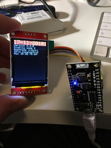
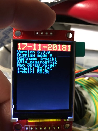
all pics: Displaymode 5
Pic 1: Firmware v6_3 prebuild release-bin

Pic2: Firmware raidolo self-compiled; imagerotate 0

Pic 3: Firmware raidolo self-compiled; imagerotate 1

(- don't worry about displaycols not set right)
- green bars only show up at displayrotate 0
- (no pic) displaytext is working well
--> just have to test with this graphictest wether the line at the left and the line at the bottom are hardware-errors (but i think since the "displaymode-5-text" is is postponed one pixel in x and one pixel in y it seems like there is a align-problem in the tasmota-firmware?)
bastelfix
on 19 Dec 2018
@bastelfix Uh, the green bars are probably my fault, I’ve set them somewhere in the code while testing! Sorry for that, I’ll fix them tomorrow if I have sometime, but it’s not an issue with the display. I didn’t notice them before the upload because I’m using displaymode 0, to set my own text with the displaytext commands.
The last line at the bottom and the right one to me looks like a rows/cols issue?
Try DisplayMode 0, and then some DisplayText command, I think I’ve messed up a bit the default DisplayMode 4 because I don’t use it, nothing too hard to fix anyway.
Just let me know if the custom text is working fine.
raidolo
on 22 Dec 2018
@bastelfix I've committed few changes to bring back the default behaviour of tasmota 6.3 with DisplayModes 1-5
https://github.com/raidolo/Sonoff-Tasmota/commit/d4c1f26427079512aca1c249f0caceec27c5eade
You still have to set DisplayCols Rows, and Rotation.
Here are mine:
09:56:03 MQT: stat/thermo/RESULT = {"DisplayCols1":27}
09:56:09 CMD: DisplayRows
09:56:09 MQT: stat/thermo/RESULT = {"DisplayRows":15}
09:56:16 CMD: DisplayRotate
09:56:16 MQT: stat/thermo/RESULT = {"DisplayRotate":1}
Hope that helps.
Cheers!
raidolo
on 22 Dec 2018
Is It possible to make little icons/picture/drawings for an LCD display? I want to show this icon 🔥 but I only have an LCD display. I also want to show °.
AalianKhan
on 28 Jan 2019
Hello Raidolo,
i have tried your code, but it won't compile.
I've got a lot of errors:
`xdrv_03_energy:169:29: error: invalid use of Boolean expression as operand to 'operator--'
 energy_power_steady_cntr--;

                         ^
xdrv_03_energy:197:95: error: invalid initialization of reference of type 'byte& {aka unsigned char&}' from expression of type 'bool'
 if (EnergyMargin(0, Settings.energy_min_power, energy_power_u, flag, energy_min_power_flag)) {

                                                                                           ^
xdrv_03_energy:139:9: error: in passing argument 5 of 'boolean EnergyMargin(byte, uint16_t, uint16_t, byte&, byte&)'
boolean EnergyMargin(byte type, uint16_t margin, uint16_t value, byte &flag, byte &save_flag)
^
xdrv_03_energy:201:95: error: invalid initialization of reference of type 'byte& {aka unsigned char&}' from expression of type 'bool'
 if (EnergyMargin(1, Settings.energy_max_power, energy_power_u, flag, energy_max_power_flag)) {

                                                                                           ^
xdrv_03_energy:139:9: error: in passing argument 5 of 'boolean EnergyMargin(byte, uint16_t, uint16_t, byte&, byte&)'
boolean EnergyMargin(byte type, uint16_t margin, uint16_t value, byte &flag, byte &save_flag)
^
xdrv_03_energy:205:101: error: invalid initialization of reference of type 'byte& {aka unsigned char&}' from expression of type 'bool'
 if (EnergyMargin(0, Settings.energy_min_voltage, energy_voltage_u, flag, energy_min_voltage_flag)) {

                                                                                                 ^
xdrv_03_energy:139:9: error: in passing argument 5 of 'boolean EnergyMargin(byte, uint16_t, uint16_t, byte&, byte&)'
boolean EnergyMargin(byte type, uint16_t margin, uint16_t value, byte &flag, byte &save_flag)
^
xdrv_03_energy:209:101: error: invalid initialization of reference of type 'byte& {aka unsigned char&}' from expression of type 'bool'
 if (EnergyMargin(1, Settings.energy_max_voltage, energy_voltage_u, flag, energy_max_voltage_flag)) {

                                                                                                 ^
xdrv_03_energy:139:9: error: in passing argument 5 of 'boolean EnergyMargin(byte, uint16_t, uint16_t, byte&, byte&)'
boolean EnergyMargin(byte type, uint16_t margin, uint16_t value, byte &flag, byte &save_flag)
^
xdrv_03_energy:213:101: error: invalid initialization of reference of type 'byte& {aka unsigned char&}' from expression of type 'bool'
 if (EnergyMargin(0, Settings.energy_min_current, energy_current_u, flag, energy_min_current_flag)) {

                                                                                                 ^
xdrv_03_energy:139:9: error: in passing argument 5 of 'boolean EnergyMargin(byte, uint16_t, uint16_t, byte&, byte&)'
boolean EnergyMargin(byte type, uint16_t margin, uint16_t value, byte &flag, byte &save_flag)
^
xdrv_03_energy:217:101: error: invalid initialization of reference of type 'byte& {aka unsigned char&}' from expression of type 'bool'
 if (EnergyMargin(1, Settings.energy_max_current, energy_current_u, flag, energy_max_current_flag)) {

                                                                                                 ^
xdrv_03_energy:139:9: error: in passing argument 5 of 'boolean EnergyMargin(byte, uint16_t, uint16_t, byte&, byte&)'
boolean EnergyMargin(byte type, uint16_t margin, uint16_t value, byte &flag, byte &save_flag)
^
xdrv_03_energy:258:30: error: invalid use of Boolean expression as operand to 'operator--'
       energy_mplr_counter--;

                          ^
exit status 1
invalid use of Boolean expression as operand to 'operator--'`
How can i compile this code?
 Edelfalke
on 1 Jun 2019
Edelfalke
on 1 Jun 2019
Hi all, newbie here! I have compiled the latest developement with following https://github.com/arendst/Tasmota/wiki/Displays and when trying to run display command i get {"Command":"Unknown"} is there something else I must do?
 grego1981
on 4 Dec 2019
grego1981
on 4 Dec 2019
@grego1981 - I got the same results, you need to be sure to configure the screen properly first with the correct pin mappings within the Module menu first.
 adamrunner
on 5 Dec 2019
adamrunner
on 5 Dec 2019
Check that you have tasmota module uncommented in platformio.ini.
I've just tested my 16x2 and 128x32 displays and after few hours they are working!
 saikek
on 19 Jan 2020
saikek
on 19 Jan 2020
Hi all, I'm trying to use SSD1306 OLED display.
But whatever I do, screen keeps dark.
Using commands like displaytext returning no errors.
GPIOs set in configuration.
I2Cscan finds device at 0x3c.
Any ideas? :)
 maddingamer
on 2 Feb 2020
maddingamer
on 2 Feb 2020
Hi all, I'm trying to use SSD1306 OLED display.
But whatever I do, screen keeps dark.
Using commands like displaytext returning no errors.
GPIOs set in configuration.
I2Cscan finds device at 0x3c.Any ideas? :)
Could you try running all commands - like setting mode, resolution, displaymode, displaymodel ?
Start with displaymode that prints just local time.
Also try mqtt_topic/cmnd/POWER off and mqtt_topic/cmnd/POWER on.
That helped me, but i was not able to find patterns for that.
saikek
on 3 Feb 2020
reflashed my device after couple of days off.. now it just works magically ^^
Now I only have to figure out on how to increase size of the text displayed and how to display mqtt stuff.. thx tho saikek :)
maddingamer
on 14 Feb 2020
I know this thread has some old content in it but is it still required to use the development branch to get OLED i2c displays working?
 ril3y
on 15 Feb 2020
ril3y
on 15 Feb 2020
I know this thread has some old content in it but is it still required to use the development branch to get OLED i2c displays working?
No, it works on release 8.10 version for me.
saikek
on 17 Feb 2020
Got it working. Struggled a couple of hours yesterday, so I tried a noterh Vemos D1 today and it worked direct, so my old D1 is now in the trash.
How can I get just some of my MQTT topics and messages displayed? Right now it shows all other Tasmota topics and values.
 Quart666
on 7 Mar 2020
Quart666
on 7 Mar 2020
Related issues
 kckepz
·
3Comments
kckepz
·
3Comments
 luisfpinto
·
3Comments
luisfpinto
·
3Comments
 smadds
·
3Comments
smadds
·
3Comments
 JoergZ2
·
3Comments
JoergZ2
·
3Comments
 Joeyhza
·
3Comments
Joeyhza
·
3Comments
Most helpful comment
See https://github.com/arendst/Sonoff-Tasmota/tree/development_display
This is with NO support.