Hi,
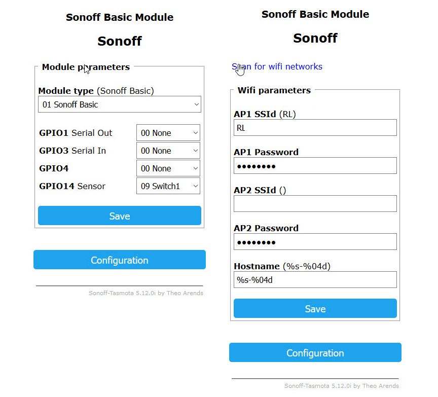
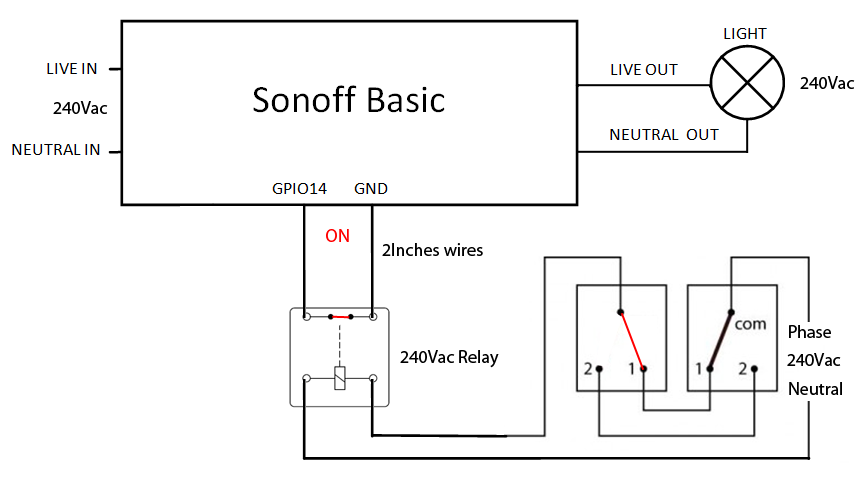
I have flashed a sonoff basic with tasmota and set GPIO14 Sensor -> 09 Switch1.
I use home assistant and wall shitches and everything works ok.
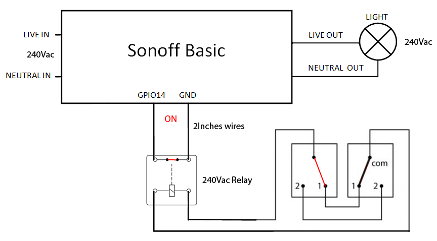
I have connected all like in this picture.

It is worked ok for two days and after that the module died.
I have try with one more module and same thing. Works ok for one day and after that the module died.
Could you help me please?
Thank you
Sorry my english!
 Notpts
All 27 comments
There is nothing wrong with the function of the relay contact for switching the sonoff.
How long are the wires from the contact to the sonoff? You may get unwanted signals (with too high levels)
if the are to long. Connect a pullup resistor on Gpio 14. A capacity about a few pf on Gpio 14 and Gnd is a good idea too...
But your schematic for powering the relay cant be correct. No power supply?!
 Jason2866
on 29 Mar 2018
Jason2866
on 29 Mar 2018
I dont see anything wrong, only thing i would do different is use a 4,7kΩ vcc to Gpio14 (pullup) .
Have done this many times with Sonoff basic, one i have is been going strong for about a year now.
 maragelis
on 29 Mar 2018
maragelis
on 29 Mar 2018
Ok I go try burn one more sonoff :-(
I have no unwanted signals it works ok for a day and then... doesen´t work anymore. Module died.
This time i go use a pullup resistor like in this picture.

Notpts
on 29 Mar 2018
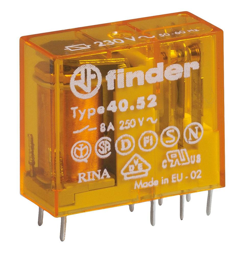
What type is the 240Vac relay?
 curzon01
on 29 Mar 2018
curzon01
on 29 Mar 2018
The relay is:

Notpts
on 29 Mar 2018
And my setup:

Notpts
on 29 Mar 2018
I think to know what the problem is.
When I turn on the wall switch like in this picture:
and turn off with home assistant the relay remains on.
Could be a problem?
Notpts
on 29 Mar 2018
Thats a trade off you have to live with. thats not the problem burning your devices. Add the resistor you should be ok.
maragelis
on 29 Mar 2018
I think the diagram might be incomplete or it is an perpetual motion machine. I can see how this can work on AC side, but how is the relais-coil powered? There are two switches (wall switches?) but I do not see any power line (phase, neutral). How does it work?
Only asking because if the diagram is wrong in that case it could be that other details are missing too?
curzon01
on 29 Mar 2018
Its easy maybe this will help
maragelis
on 29 Mar 2018
??? not truly
curzon01
on 29 Mar 2018
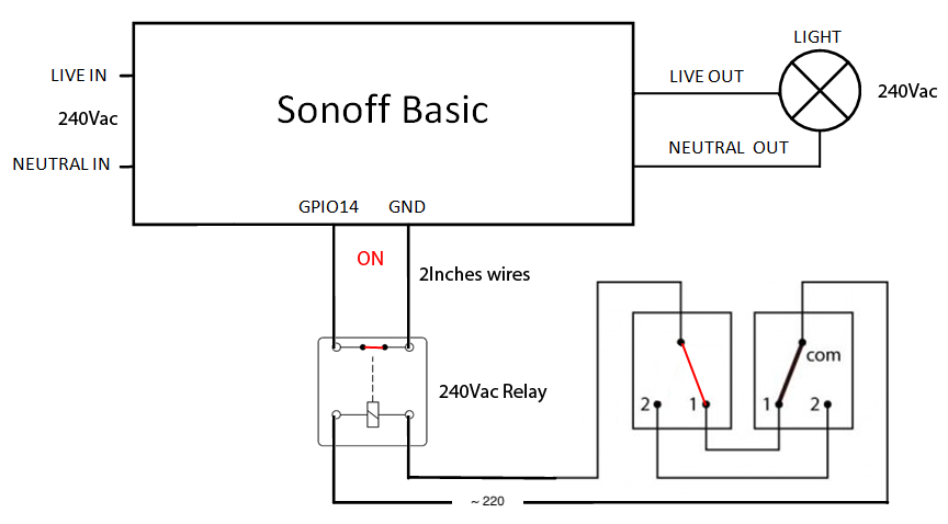
The diagram is not correct you are right!
This is the correct diagram. Sorry!
Notpts
on 29 Mar 2018
How about connecting the two-way-connection directly to GPIO14/GND without any mains or relay?
 renne
on 30 Mar 2018
renne
on 30 Mar 2018
As mentioned by @Jason2866 the question how long are the wires from relay contact to Sonoff could become important but unfortunately we still do not know how long and which wires they are. So again, how long are the wires and what are the cable cross-section from relay contact to the Sonoff? Protection can be done by a RC circuit already suggested by @Jason2866.
curzon01
on 30 Mar 2018
I think what he is trying to implement in his sketch is a 3 way switch (two switches to control a load). If the line and the load are in the same box as one of the switches then this will work. The 3 way switches and the wires in the wall simply work on 3.3 V DC logic rather than AC current. If the line and the load are in separate boxes you need two sonoffs (one in each box) because there is no way to avoid a switch combinations that would send AC current int the sonoff via GPIO14. I think the confusion is he does not need that relay. As curzon01 stated ......there is no AC power for the switches downstream of the unnecessary relay. Perhaps the unnecessary relay is pulling more 3.3 V DC current than the Sonoff can supply and therefore, after about a day.....kills the sonoff.
 MTGS69
on 30 Mar 2018
MTGS69
on 30 Mar 2018
@TOBYBEAR69 - the last sheet from Notpts works.
I do not see that an isolated relay contact is pulling more current than Sonoff can supply.
My fear is the contact bouncing in combination with long wires (we still don't know that fact). The very fast bounce of contacts for on/off can induce very short high voltages (>6V and <0V) peaks on the GPIO input and this may damage the input/chip.
curzon01
on 30 Mar 2018
My main point had less to do with the what was killing the Sonoff and more with the correct way to connect a 3 way switch to a Sonoff if the line and load are in the same box. The last sheet may work......not entirely convinced....but for the sake of discussion....I will assume that it does). There is a much easier (and safer) solution that will absolutely fix his problem. Assuming he actually has AC power to both switch boxes (I've worked on lots of 3 way switches and never encountered this but again...lets assume that is the case). First, disconnect the AC power lines from the box that does not contain the Sonoff (i.e cap them off as they are NOT required). Throw away the relay (or save for a different project). Hook GPIO14 from the Sonoff to the common terminal on the switch in the near box. Look which wire (red,white or black typical for US) is connected to the common terminal on the far switch (I use black). Go back to the first switch box and connect that color wire (in my case black) to the GND wire coming from the Sonoff. Then connect the remaining two wires (red and white in my case) to the remaining two wires on the other two screw terminals on both switches. The order of the last two wires connected to the non-common screw terminals does not matter. Note that at this point the only current passing through the switches and connecting wire between the switches is 3.3 V DC and the length of the wires running through the wall will have no impact on proper operation.
MTGS69
on 2 Apr 2018
@TOBYBEAR69
You describe a solution which is ok in your region. In other regions this way is NOT allowed.
So, as in many things, there is not the one and only solution...
Jason2866
on 2 Apr 2018
Fair comment. For my own understanding of how things work outside the US, a) if you have 220 V on both sides of the relay then what purpose does the relay serve? b) where is the power on switch side supplied from (not clear from any of the sketches)? If you only had a single switch would you still need a relay and if so would you still have 220 AC power on both sides of the relay? Not trying to be argumentative (sometimes you cannot tell just reading words). Rather, I am truly curious.
MTGS69
on 2 Apr 2018
coil nominal voltage 230V AC - GPIO14 3,3V DC !!!
Semms to work - one day! When you switch off a coil the voltage can raise up ernourmous (dirac pulse) in the opposite way, a flyback diode (Freilaufdiode) may work but i prefer using a 3,3v DC relais, costs 2,58 Euro
 Dickesplumpel
on 3 Apr 2018
Dickesplumpel
on 3 Apr 2018
@Dickesplumpel - I'm just wondering how do you want connect a recovery diode on an AC relay. Also wondering what's the rleation between a coild inductive created negative voltage by switch off with the isolated contacts where you use e.g. 3,3V - it's isolated - otherwise what is a relay good for
curzon01
on 3 Apr 2018
I see my error - forget it :))
Dickesplumpel
on 3 Apr 2018
But a 1k Resistor between GPIO14 and the Relay may do a good job!
Dickesplumpel
on 3 Apr 2018
Guys the coil is on the 220vac side you don’t need anything. The relay switch is on the sonoff side. The diagram is correct and doesn’t need any changing the only thing I would do is put the sonoff as a third switch and not in between the switch and light.
maragelis
on 3 Apr 2018
I added a switch to the GPIO14 of the sonoff to recognize if closed or
open. I put a resistor of 4,7k in the curcuit and it works fine for nearly
a year right now. The sonoff starts and stops the waterpump (Grundfoss
Magna) and the
gpio14 is connected to a relay of the control of the pump to recognize if
the pump runs or if it has an error an stopped. When stopped because of an
error stop and restart in 5 minutes (domoticz)
2018-04-03 14:58 GMT+02:00 Panagiotis notifications@github.com:
Guys the coil is on the 220vac side you don’t need anything. The relay
switch is on the sonoff side. The diagram is correct and doesn’t need any
changing the only thing I would do is put the sonoff as a third switch and
not in between the switch and light.—
You are receiving this because you were mentioned.
Reply to this email directly, view it on GitHub
https://github.com/arendst/Sonoff-Tasmota/issues/2286#issuecomment-378240637,
or mute the thread
https://github.com/notifications/unsubscribe-auth/Ad_FDK9IuHrfPQRxgTNLWBZHTMnSQOwfks5tk3H7gaJpZM4S_-Xo
.
Dickesplumpel
on 3 Apr 2018
This issue has been automatically marked as stale because it has not had recent activity. It will be closed if no further activity occurs. Thank you for your contributions.
![stale[bot] picture](https://avatars3.githubusercontent.com/in/1724?v=4&s=40) stale[bot]
on 6 Jun 2018
stale[bot]
on 6 Jun 2018
This issue will be auto-closed because there hasn't been any activity for a few months. Feel free to open a new one if you still experience this problem.
stale[bot]
on 21 Jun 2018
Related issues
 abzman
·
3Comments
abzman
·
3Comments
 belidzs
·
3Comments
belidzs
·
3Comments
 grizewald
·
3Comments
grizewald
·
3Comments
 luisfpinto
·
3Comments
luisfpinto
·
3Comments
 ximonline
·
3Comments
ximonline
·
3Comments