Tasmota: Support for etekcity Voltson WiFi power monitoring outlet - ESW01
This is a very inexpensive switch and power monitor. Eg: https://www.amazon.com/Etekcity-Voltson-Outlet-Monitoring-Required/dp/B074GYTRFX (3 pack at $13.33 ea shipped, or 4-pack for $12.50 ea). The smartphone app vesync is however not well liked, and a Tasmota firmware replacement, if possible, would make it much handier.
FCC photos: https://fccid.io/2AB22ESWO1-USA/Internal-Photos/Internal-photos-3114486
Uses ESP8266ex for WiFi, unsure about power monitoring chip
I do not see serial programming pins broken out, but the WiFi module has a lot of pins broken out. I do not have one, so I don't know how hard it would be to open up the case.
Any chance of this being supported?
 zephyrr
All 62 comments
@zephyrr this post claims that it works.
 mcolyer
on 28 Jan 2018
mcolyer
on 28 Jan 2018
@mcolyer Alas, they don't say anything about the power monitoring, so I suspect they just have on/off control.
zephyrr
on 29 Jan 2018
I was curious about that part as well. I ordered one so I’ll see what I can
find. I was looking at using sonOta to possibly avoid having to solder
things.
On Sun, Jan 28, 2018 at 18:54 zephyrr notifications@github.com wrote:
@mcolyer https://github.com/mcolyer Alas, they don't say anything about
the power monitoring, so I suspect they just have on/off control.—
You are receiving this because you were mentioned.Reply to this email directly, view it on GitHub
https://github.com/arendst/Sonoff-Tasmota/issues/1679#issuecomment-361126733,
or mute the thread
https://github.com/notifications/unsubscribe-auth/AAAFkFOmHPySM2tJIOv1j6nEtO2-LuVJks5tPTLwgaJpZM4RotPQ
.
mcolyer
on 29 Jan 2018
I'm somewhat of a beginner in this area, but I thought Sonata was a method of bootstrapping to Tasmota from the pre-installed Sonoff firmware from Itead - that is, start with their Firmware Over the Air implementation to load Tasmota onto the chip, then use Tasmota's facilities thereafter. Have I misunderstood?
The Voltson is of course not from Itead or part of the Sonoff family, so it would probably not have their OTA firmware loading (it may or may not have it's own). I say probably, because of course there's some possibility that Etekcity contracted with Itead for their firmware, but I see no evidence of that.
zephyrr
on 29 Jan 2018
I'm somewhat of a beginner in this area, but I thought Sonata was a method of bootstrapping to Tasmota from the pre-installed Sonoff firmware from Itead - that is, start with their Firmware Over the Air implementation to load Tasmota onto the chip, then use Tasmota's facilities thereafter. Have I misunderstood?
Nope that's totally correct, my working theory is that the hardware is almost identical which means that the firmware should just work.
The Voltson is of course not from Itead or part of the Sonoff family, so it would probably not have their OTA firmware loading (it may or may not have it's own). I say probably, because of course there's some possibility that Etekcity contracted with Itead for their firmware, but I see no evidence of that.
It's probably different but since the underlying hardware is very similar, I'm hoping that it isn't radially different. There's a project here which talks about proxying the traffic to etekcity's servers and it mentions there being an OTA upgrade capability.
This is a link to the SonOTA which I was hoping to use as a starting point for doing something similar for Etekcity Voltsons.
mcolyer
on 29 Jan 2018
@mcolyer have you made any progress on getting power monitoring to work? I was able to flash tasmota on my ESW01 units and get on/off control but getting power monitoring to work has eluded me. The power monitoring chip seems to work like the one in the Sonoff pow but I just can't get tasmota reading it correctly. I've documented my progress in that thread you linked earlier (here).
 seanauff
on 11 Feb 2018
seanauff
on 11 Feb 2018
@seanauff it sounds like you got further than I have. I ended up going in a completely different direction and am stubbing out the Etekcity server in my new voltlet project and then tying that into MQTT, which means you don't have to break open the case to reflash. I don't have energy monitoring working yet in that project but I understand how to do it - just haven't had the time to implement yet.
Aside, I couldn't figure out how to get the case off of the plug without breaking it. Is there a trick?
mcolyer
on 11 Feb 2018
@mcolyer That looks like a nifty way to avoid reflashing!
The case is annoying to open - though once you do one it gets easier for the 2nd. There are 7 total plastic clips around the edge of the clamshell. You need to use a small screwdriver to pry at each of these locations to get it apart. The first one is the hardest, I used a razor blade to separate the halves enough to get the screwdriver in, then proceeded around the edge one by one. I started at the location directly opposite the button. You can kind of see a little 1/4" gap where each clip is. I didn't take any pictures of the case when I had it open, unfortunately.
seanauff
on 11 Feb 2018
i was able to flash 2 units, though power monitoring doesnt work. it does have a HLW8012 in it though
this is the config I am currently using (credit Blawson327 on smartthings)
{ “EtekCity”, // EtekCity Voltson (ESP8266)
GPIO_HLW_SEL, // GPIO00 Unknown
0, // GPIO01 Unknown
0, // GPIO02 Unknown
0, // GPIO03 Unknown
GPIO_REL1, // GPIO04 Relay/LED
GPIO_LED1_INV, // GPIO05 Blue LED
0, 0, 0, 0, 0, 0, // Flash connection
GPIO_HLW_CF1, // GPIO12 Unknown
GPIO_HLW_CF, // GPIO13 HLW8012 CF (Power)
GPIO_KEY1, // GPIO14 Button
0, // GPIO15 Unknown
0, // GPIO16 Unknown
0
}
 Eno423
on 9 Mar 2018
Eno423
on 9 Mar 2018
As I dont have the ability, is anyone willing to poke around to get Power monitoring sorted?
Ill help in any way I can
Eno423
on 14 Mar 2018
I would like power monitoring working as well, unfortunately I am stumped because although it has a HLW8012 in it, it is not providing the expected outputs.
seanauff
on 16 Mar 2018
This issue has been automatically marked as stale because it has not had recent activity. It will be closed if no further activity occurs. Thank you for your contributions.
![stale[bot] picture](https://avatars3.githubusercontent.com/in/1724?v=4&s=40) stale[bot]
on 6 Jun 2018
stale[bot]
on 6 Jun 2018
bump still unable to identify the proper way to get PM working correctly
values are all over the place
Eno423
on 7 Jun 2018
This issue has been automatically marked as stale because it has not had recent activity. It will be closed if no further activity occurs. Thank you for your contributions.
stale[bot]
on 22 Jul 2018
This issue will be auto-closed because there hasn't been any activity for a few months. Feel free to open a new one if you still experience this problem.
stale[bot]
on 7 Aug 2018
Does anyone has manage to get power monitoring working?
 oriolism
on 16 Aug 2018
oriolism
on 16 Aug 2018
In examining the network traffic of a recently-bought unit, it appears that they've:
a) changed the name of their server (to server22)
b) added encryption
thus, the voltlet intercept software doesn't work with it now.
But, on the upside, the RX/TX, GPIO0 and GND pins are accessible along the top edge of the ESP's daughterboard, and VCC is accessible on the main board without disassembling the device beyond just opening the case.
Not as easy as the Sonoff devices, which very conveniently present the lines needed for flashing.
But it looks doable. Unless they altered the bootloader to prevent re-flashing.
 glyndon
on 28 Aug 2018
glyndon
on 28 Aug 2018
I already have the Sonoff firmware working I believe the purpose the OP & others have on this thread is getting the Power monitoring working.
I am not running the Voltlet as I dont need it with the Sonoff FW on the unit(s)
Eno423
on 28 Aug 2018
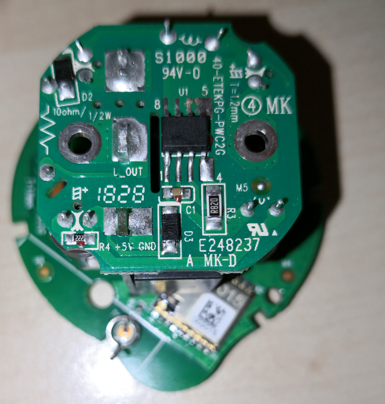
I've traced the power-monitoring chip, and studied its online marketing data (the engineering datasheet is Chinese only, and I can't read that) and learned:
The Voltson plug device includes a voltage/current sensor, implemented using a HLW8012 chip, pin 7(CF1) to GPIO 12/MISO (designated '~V') and HLW pin 6(CF) to GPIO 13/MOSI (designated 'Pw').
Documentation for the HLW8012 does not seem to be available in english.
But a translate of the page at http://www.hiliwi.com/products_detail/&productId=36.html reveals what the pins are, and what they send.
The voltage and current measurements are encoded as frequencies, 50% duty-cycle, sent to the GPIO's. By coding them to generate interrupts, and measuring the time between pulses, you'd have the raw values from which V and A can be calculated.
Maybe that provides enough to get someone started implementing a feature for these.
glyndon
on 4 Sep 2018
The main issue was always where to find GPIO_HLW_SEL as this gives us the map for voltage and such
 iceman73
on 12 Sep 2018
iceman73
on 12 Sep 2018
The main issue was always where to find GPIO_HLW_SEL as this gives us the map for voltage and such
I am assuming this means "which ESP pin controls SEL on the HLW chip."
To that end, I just now lifted the HLW8012 chip from the board, and pin 8 (SEL) is strapped to Vdd (pin 1).
Also, I just updated my comment above with the pin mapping of the CF and CF1 pins to the other GPIO's.
Strapping SEL doesn't seem to make sense, since it is documented as changing the nature of the output signal, but the trace is nonetheless there. I tested the continuity, just to be sure I wasn't seeing it wrong.
glyndon
on 13 Sep 2018
Glad to see people picking this back up
Eno423
on 13 Sep 2018
@glyndon since you lifted the chip and traced it, did you happen to trace the VDD pin1 as well? Maybe they are labeled backwards?
Serial number | Pin name | Types of | description
-- | -- | -- | --
1 | VDD | power supply | 5V voltage
2 | V1P | Analog input | Current channel differential input with a maximum differential input voltage range of ±43.75mV
3 | V1N | Analog input
4 | V2P | Analog input | Positive input of voltage channel, maximum input signal ±700mV
5 | GND | Analogue | Analogue
6 | CF | Digital output | Output active power high frequency pulse, pulse duty cycle 50%
7 | CF1 | Digital output | SEL=0, CF1 output current RMS, pulse duty cycle 50% SEL=1; CF1 output voltage RMS, pulse duty cycle 50%
8 | SEL | Digital input | Configure CF1 output current or voltage rms value, internal pull-down
iceman73
on 21 Sep 2018
I'm not clear on what you're asking beyond what I already wrote.
VDD goes to +5v supply, and SEL is strapped to it via a trace that passes under the chip. I saw it with a magnifier, and then tested using an ohmmeter to be sure I was seeing it correctly.
glyndon
on 21 Sep 2018
Ok Got it
iceman73
on 21 Sep 2018
glad to see other people working on this. I put SEL on analog, then turned switch on, i have 3 different options i the firmware.

{ "Voltron", // eletricity
0, // GPIO00 D3 not_HLW_SEL
0, // GPIO01 TX not_HLW_SEL
0, // GPI O02 D4 not_HLW_SEL
0, // GPIO03 RX not_HLW_SEL
GPIO_REL1, // GPIO04 D2 not_HLW_SEL
GPIO_LED2_INV, // GPIO05 D1 not_HLW_SEL blue led
0, 0, 0, 0, 0, 0, // Flash connection
GPIO_HLW_CF, // GPIO12 D6
GPIO_HLW_CF1, // GPIO13
GPIO_KEY1, // GPIO14 D5
GPIO_HLW_SEL, // GPIO15 D8
GPIO_USER, // GPIO16 D0 Wemos Wake
GPIO_ADC0, // ADC0 A0 Analog input
},
{ "Voltron 2", // eletricity
0, // GPIO00 D3 not_HLW_SEL
0, // GPIO01 TX not_HLW_SEL
0, // GPI O02 D4 not_HLW_SEL
0, // GPIO03 RX not_HLW_SEL
GPIO_REL1, // GPIO04 D2 not_HLW_SEL
GPIO_LED2_INV, // GPIO05 D1 not_HLW_SEL blue led
0, 0, 0, 0, 0, 0, // Flash connection
GPIO_HLW_CF, // GPIO12 D6
GPIO_HLW_CF1, // GPIO13
GPIO_KEY1, // GPIO14 D5
GPIO_USER, // GPIO15 D8
GPIO_HLW_SEL, // GPIO16 D0 Wemos Wake
GPIO_ADC0, // ADC0 A0 Analog input
},
{ "Voltron 3", // eletricity
0, // GPIO00 D3 not_HLW_SEL
0, // GPIO01 TX not_HLW_SEL
0, // GPI O02 D4 not_HLW_SEL
0, // GPIO03 RX not_HLW_SEL
GPIO_REL1, // GPIO04 D2 not_HLW_SEL
GPIO_LED2_INV, // GPIO05 D1 not_HLW_SEL blue led
0, 0, 0, 0, 0, 0, // Flash connection
GPIO_HLW_CF, // GPIO12 D6
GPIO_HLW_CF1, // GPIO13
GPIO_KEY1, // GPIO14 D5
GPIO_USER, // GPIO15 D8
GPIO_USER, // GPIO16 D0 Wemos Wake
GPIO_HLW_SEL,
},
 redwoodimage
on 25 Sep 2018
redwoodimage
on 25 Sep 2018
there is only one transistor for yellow and relay and they are connected, the SEL needs to go threw transistor to convert logic to 3.3 but there isn't one, i think they pulled SEL hi connecting it to vcc all the time it outputs current only, it might just guess voltage at 120v or can it get the volts from knowing the amps and watts from cf and cf1 and gets the voltage from there.
redwoodimage
on 25 Sep 2018
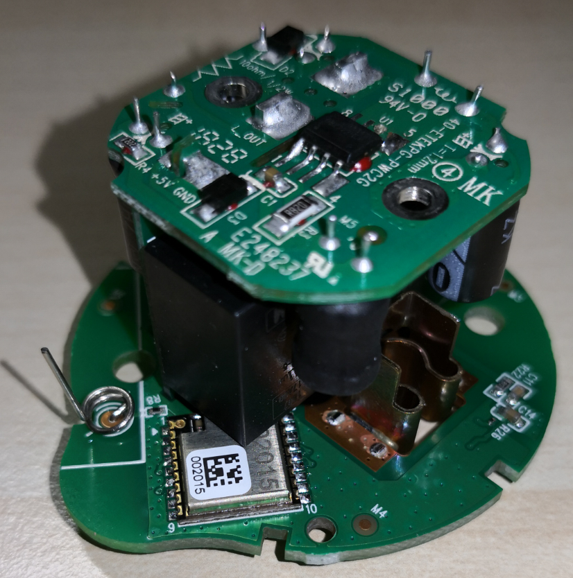
Hey guys, happy so see some progress here. Actually I got an Etekcity ESW01-EU which is built up slightly different to the US version mentioned above. You can open it by simply unscrewing two (really) small Torx and get the board out with four Philipps screws.
But the ESP(?) chip is one that I haven't seen previously. Can someone identify it so I know which pins are which? It has 9 pins on each side, pins are 1mm apart, antenna is not on the chip itself and says something like ...2015 on the chip and 002015 on a label.
 gitolicious
on 8 Oct 2018
gitolicious
on 8 Oct 2018
Anyone have any thoughts as to why power monitoring might not be working? From what I can tell we believe we have at the pins correct, right? Could the tasmota implementation of the hlw8012 be flawed? Is there potentially something between the hlw8012 that's different than say the sonoff pow? Just trying to brainstorm so we can get there working. It would great if we could get $10 plugs with power monitoring working with tasmota.
 CCoffie
on 2 Feb 2019
CCoffie
on 2 Feb 2019
Hey guys,
quick feedback to the new Etekcity ESW01-EU version. After a lot of measuring, tracing and trial&error I was finally able to flash the device.
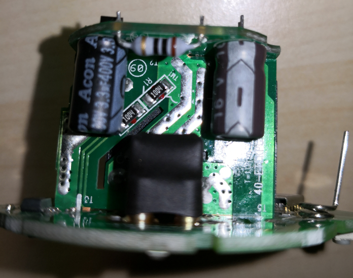
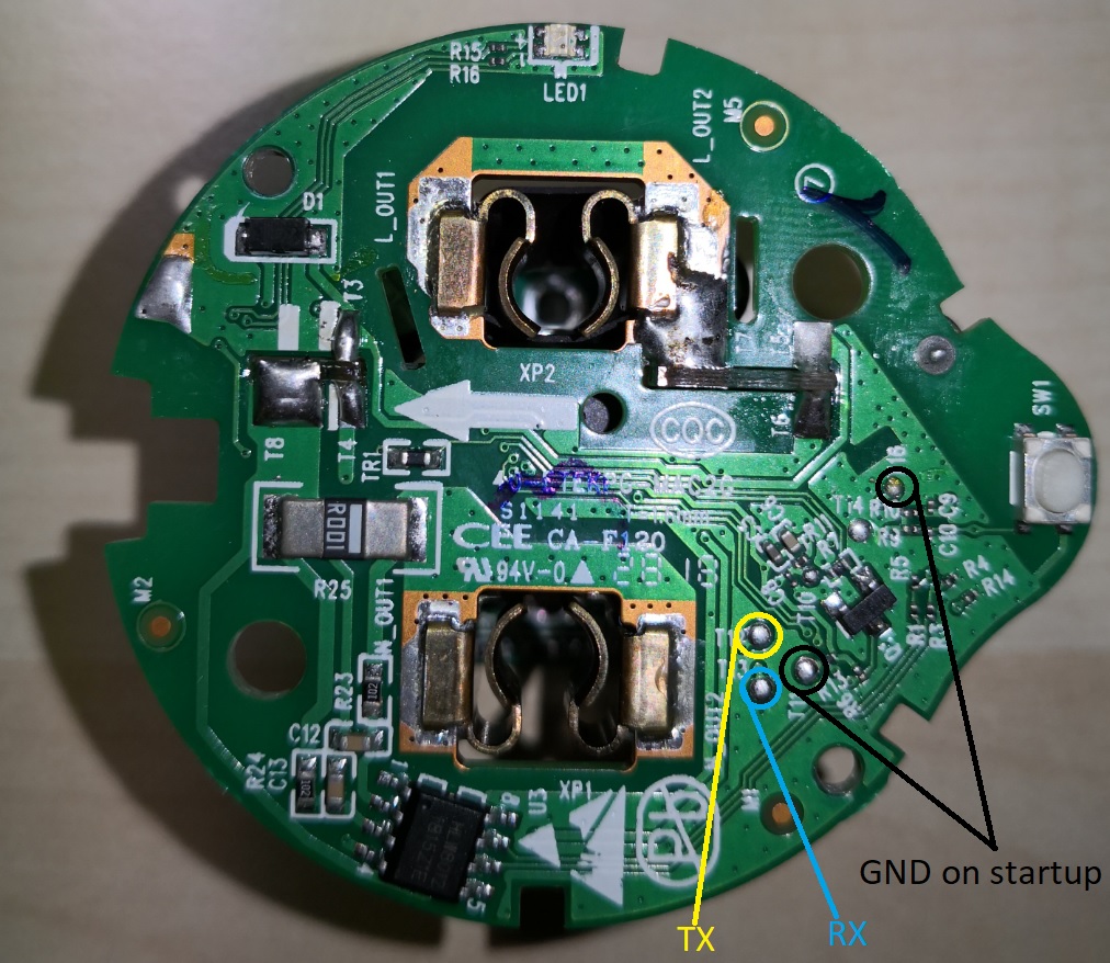
In the end, all necessary pads for flashing were easily accessible with test hooks and pogo pins. Attach 5V and GND at the bottom:
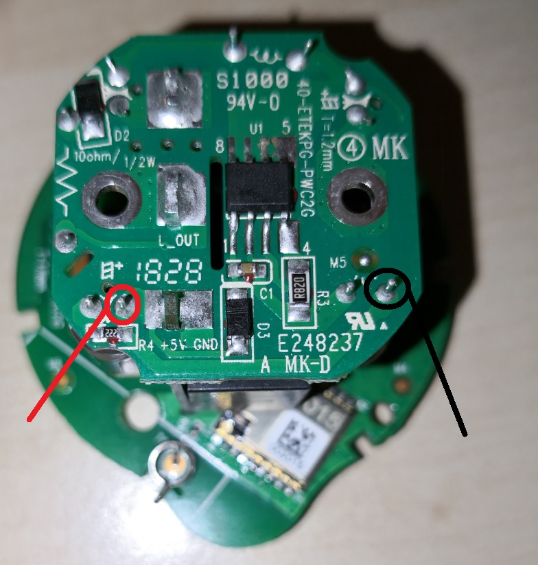
Then during boot, connect T11 and T16 pads to GND. For flashing, T12 is TX, T13 is RX. Easiest to flash with pogo pins.
For the ESP itself, I am still unsure which model exactly it is. None of the pinouts on the Internet were a match for this one... Pins that I found:
Pin Usage   Tasmota pin     Pin Usage   Tasmota pin
1   ANT                 18  GND
2   GND (T14)               17  3V3
3                   16
4                   15  TX (T12)
5   LED yellow  D0 GPIO16 Led2      14  RX (T13)
6   SW1     D5 GPIO14 Button1   13  LED blue    D1 GPIO5 Led1
7   HLW8012/CF1 D6 GPIO12 HLWBL CF1 (?) 12  REL1    D2 GPIO4 Relay1
8   HLW8012/CF  D7 GPIO13 HLW8012 CF    11  GPIO0? (T11)
9                   10
Just as in the discussions over at SmartThings, so far I was unable to find the correct pin for HLWBL SEL and HLWBL CF1. I am getting the correct Power but invalid values for Voltage and Current.
Voltage | 273 V
Current | 10.132 A
Power   | 5 W
In the same situation, my Sonoff Pow is showing these values which are more realistic:
Voltage | 237 V
Current | 0.087 A
Power   | 5 W
Any ideas to fix this welcome!
gitolicious
on 19 Feb 2019
Did anyone ever figure out the proper resistor values for calibrating these? I'd rather not tear the board stack apart to try to figure out what it is, if I can help it.
fyi @gitolicious on my US-market device the SEL pin is permanently pulled high, so you can only read current and voltage.
 brandond
on 6 Jun 2019
brandond
on 6 Jun 2019
The resistor/cap network around the HLW8012 is very similar to what's around the Sonoff, per this discussion.
Differences:
"SEL" is strapped high, meaning CF1 only puts out voltage. (People above think it's current. The linked to document suggests it's voltage. Either would be fine since it's nothing to determine the other when you have power. My guess is they did this to avoid having a level shifter on the board. GPIO 16 is brought out of the 8266 daughter card to the power measurement card, but it seems to just terminate there. My guess is an earlier prototype used it to select and they figured out how they could save a few cents.
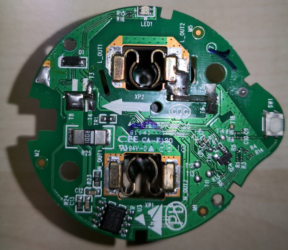
The shunt resistor seems to be a normal 0Ohm but high current resistor. There is no other connectivity like in the diagram. You can see it in Gitolicious's post above, 3rd picture with the HLW8012. G's is marked "R001" The one in my US version is marked R002. Looks like an 0812 package. Looks like they used a .001 Ohm in Europe and a .002 in the US, which makes sense.
The series resistor that is used to measure voltage is 1.92MOhms (2 953K resistors) between the Hot and the V2P input instead of the 2.82M series resistors (6 470K). In G's picture above, it looks like the European version is using 2 1MOhm resistors in series.
-The two outputs, CF1 and CF feed GPIO12 and GPIO13 through 4.7K/10K voltage dividers. Which just converts the outputs to 3.4V safe..
I'm currently trying to figure out how to compile Tasmota... :)
 twinotter
on 25 Jun 2019
twinotter
on 25 Jun 2019
Progress! I'll be starting a new ticket with this, but writing up here for the breadcrumbs...
The ESW01 doesn't use the select pin of the HLW8012.
You can get a bit of a work around using this template:
{"NAME":"ESW01-US","GPIO":[0,0,0,0,21,52,0,0,132,133,17,0,130],"FLAG":0,"BASE":6}
What it does is use the SONOFF-POW as its module. Then pins are selected as discussed in this thread. Finally, there is no SEL pin with the ESW01, but Tasmoda won't show anything if SEL is not set. So this template sets SEL to GPIO16 (which it might have actually been in an earlier version of the ESW01!).
The result is a system that works, but needs to be calibrated. Put a known wattage bulb into a lamp. Plug it in, turn it on, issue the command PowerSet
Amps will always be wrong until this bug is fixed.
The code in HlwDrvInit() in xnrg_01_hlw8012.ino correctly sets energy_current_available and energy_voltage_available based on the pins you set, even if you don't select something for GPIO_NRG_SEL. It also measures the squarewaves on the CF1 pin correct (although it duplicates voltage onto the current numbers, since SEL can't actually be changed).
Unfortunately, the code in xdrv_03_energy.ino, especially in EnergyShow() doesn't deal with a situation where energy_current_available is false very well. It should be able to calculate current from the voltage and power results.
There's another issue too... When SEL is unset, nothing seems to work. It's as if the energy module just isn't running... although manually walking through the function pointer calls isn't showing me why. I'm not sure if it's because a SONOFF-POW has to have all three inputs (I can't find the code that does any check like that). Or what else could be going on.
But anyway, there it is. The ESW01 Etekcity Voltson can be used right now with Voltage and Power results correct (within accuracy limits) with the template above. The energy code has to change a little to handle current... or alternatively to just display power and voltage if there is no SEL pin.
twinotter
on 26 Jun 2019
FYI - I have bought two batches of the US version of these plugs (ESW01-USA). They look identical from the outside, but are drastically different on the inside. One of them has two boards in a stack (FCCID ESW01-USA A25), and a yellow LED that is wired in parallel with the relay. The other version (FCCID ESW01-USA2 B02) has a single board with the relay and yellow LED individually controllable. The A25 model has a two 953K resistors in the voltage divider bridge and 0.002 ohm shunt, while the B02 model has four 470K and an 0.001 shunt, like the UK boards. This latter arrangement is also what's suggested in the HLW8012 datasheet. The A25 can be easily removed from the shell as the circular plug area pops out. The B02 has a similar circular area but is actually molded into the back shell and cannot be removed. The A25 is actually only rated for 8 amps, while the B02 is rated for 10. They both seem to contain an internal relay that is rated for 10 amps; the A25 contains a 10 amp fuse protecting the relay while the B02 has no protection fuse.


brandond
on 26 Jun 2019
Can flashing be done with an Arduino Uno?
 NovaViper
on 26 Aug 2019
NovaViper
on 26 Aug 2019
 meingraham
on 26 Aug 2019
meingraham
on 26 Aug 2019
@NovaViper - https://lmgtfy.com/?q=flashing+esp8266+with+arduino+uno
@meingraham I meant without the ESP8266, only using the Arduino Uno
NovaViper
on 26 Aug 2019
@NovaViper
What are you flashing if not the ESP82xx?
The task of flashing, in the context of this site, is to load firmware onto an ESP82xx based smart device; in particular Tasmota firmware. Thus, you question Can flashing be done with an Arduino Uno? carried with it the seemingly implied understanding that you wanted to use an Arduino Uno as the interface to use to perform the flashing of an ESP82xx based device.
"_without_ the ESP8266"... then you are not flashing Tasmota and you have come to the wrong project to seek your answer.
meingraham
on 26 Aug 2019
@NovaViper
Arduino IDE can flash 99% of all microchips so far you get the base. Used it now from up the time that the program came up. With the right adapter you can flash boot-loaders too. Very easy and work 100% of the time on my installation.
 mike2nl
on 26 Aug 2019
mike2nl
on 26 Aug 2019
@mike2nl So it can flash Sonoff plugs without needing the ESP8266 module?
NovaViper
on 26 Aug 2019
Ok.. I just noticed that I confused the name of the thing I'm asking about. In the wiki, they have this particular diagram here

I don't have that red device in the diagram, I'm wondering if I can use an Arduino Uno as an alternative to that device
NovaViper
on 26 Aug 2019
@NovaViper Sonoff devices are ESP82xx based. Tasmota is for ESP82xx based devices. You are on the Tasmota project GitHub. Thus, the Arduino Uno ESP8266 response.
meingraham
on 26 Aug 2019
The brain of a sonoff device is an esp8266 chip. And yes you can program a sonoff with an arduino uno.
You don't need any extra esp8266.
The red thing is a ftdi that connects your usb to the serial connection of the esp8266 chip of a sonoff.
Your arduino uno can be used instead of a ftdi.
Anyway, a FTDI is very cheap and very easy to use. It is worth to buy one.
If you need further assistant, please find us in the Tasmota support chat. Thanks
 ascillato
on 26 Aug 2019
ascillato
on 26 Aug 2019
@ascillato Thanks for the info!
NovaViper
on 26 Aug 2019
@ascillato Duplicate Answer :wink:
meingraham
on 26 Aug 2019
I have yet another variant of the ESW01-USA2 board, it is also molded to the casing and not easily removable. It does seem to have pads for 5v, gnd, tx, and rx available on the top surface (that could be easily POGOd), as well as a mysterious pad labeled "100". I cannot find the power monitoring chip, however I assume its the same HLW8012 found in the other revision @brandond's shared. This board is labeled "WiFi-Soctek _V2.5"

I'm hoping I can convert this without the need for destroying one to determine the pinout, but we'll see.
 kageurufu
on 20 Feb 2020
kageurufu
on 20 Feb 2020
What you read as "100" is actually "IO0" which is GPIO 0 (zero). Pull it to ground during startup to enter flash mode.
I can't really image the board is glued. Usually a clever clip mechanism or a hidden screw is in place and I would expect the HLW8012 to be at the bottom of the board.
gitolicious
on 29 Feb 2020
@gitolicious yeah, I meant to update. I got these flashed, and I think I have the pinout correct now. I haven't calibrated the power meter yet, but it's functional. It was fairly easy to do just by holding some male jumper wires against the pads
kageurufu
on 29 Feb 2020
Any ideas about the esw15-us? I load the tasmota, tried the esw1 template, can read power but no control of the relay
 OmetKs
on 29 Feb 2020
OmetKs
on 29 Feb 2020
In that case go with custom module and find the relay pin with trial&error. Your board revision might be different and the pins could have changed.
gitolicious
on 29 Feb 2020
ESW15-US, in case you interested:
GPIO # | Component
-- | --
GPIO00 | None
GPIO01 | None
GPIO02 | None
GPIO03 | None
GPIO04 | (I keave it as NONE, this is for a LED light when relay ON), I recommend leave it as NONE
GPIO05 | Relay1
GPIO09 | None
GPIO10 | None
GPIO12 | HLWBL CF1
GPIO13 | HLW8012 CF
GPIO14 | Button1
GPIO15 | HLWBL SEL
GPIO16 | Led1
OmetKs
on 8 Mar 2020
I managed to flash this outlet (ESW01-US) using the guidance here and one other thread (using 5v) VCC location. I used the template provided on the Tasmota page for this device:
https://templates.blakadder.com/etekcity-ESW01-USA.html
This is working great as a basic outlet. I am attempting a calibration but I am unable to get any telemetry data to be displayed for calibration. All values are zero.
Am I missing something?
 skeeto1983
on 18 May 2020
skeeto1983
on 18 May 2020
@skeeto1983 Are you powering it via mains, or still via 5.5v?
brandond
on 18 May 2020
I had powered it using the FTDI and the 5v pin for the purposes of the flashing. Once that was proven, I removed all the soldered leads, re-assembled the outlet and plugged it in using a kill-a-watt meter as recommended in the procedure and a 40w incandescent light bulb. I could bring up the Tasmota GUI for the outlet but all telemetry data was zero and could not be changed via the calibration commands in the console.
skeeto1983
on 18 May 2020
Has anyone successfully gotten power monitoring to work with the US version of this outlet?
skeeto1983
on 6 Jun 2020
Frustratingly, my issue above was from a single bad plug module. I flashed a second one that I had and the telemetry is working. I have a Kill-a-watt meter for calibration.
Question on the calibration though. I followed the Tasmota recommended procedure for VoltageSet, PowerSet, CurrentSet and while voltage and power are both reading dynamically when a load is placed on the plug, current appears to be frozen in place.
For example if I set the current for a 40W load then set the power, everything works great. However if I put a different load on the plug, the current setting remains static and the power setting will change to an incorrect new value. I'm assuming this is being biased by the static current setting because if I adjust current based on the new load it will again be correct.
Has anyone else encountered this?
skeeto1983
on 7 Jun 2020
Hi @gitolicious,
could you please share the template that you used for Etekcity ESW01-EU ? I purchased a couple. They are slightly different from your version and I can't take them apart completely. Hope to flash them with top access only.
Thanks
Rumoldus
 rumoldus
on 26 Oct 2020
rumoldus
on 26 Oct 2020
I am sorry, but I moved to ESPHome in the meantime, so can't be of any help with Tasmota templates as they didn't exist back when I was still using it.
The pin assignment that worked for me is mentioned in my post above, so you should be able to create your own template with that information.
gitolicious
on 27 Oct 2020
Hi @gitolicious, thanks for your quick answer.
I am using ESPHome as well, but am not aware of an implementation for this Etekcity device. Could you point me to it ? Many thanks again.
rumoldus
on 27 Oct 2020
@rumoldus esphome supports the HLW8012 chip. You should be able to figure out the rest with all the info provided above.
brandond
on 27 Oct 2020
Sure thing. Sorry for the off-topic to the Tasmota community.
<<your generic esphome and wifi config here>>

status_led:
  pin:
    number: GPIO5

output:
- platform: gpio
  id: led1
  pin: GPIO16

switch:
- platform: gpio
  name: "Relay"
  id: switch1
  pin: GPIO4
  on_turn_on:
    - output.turn_on: led1
  on_turn_off:
    - output.turn_off: led1

binary_sensor:
  - platform: gpio
    id: button1
    pin:
      number: GPIO14
      mode: INPUT_PULLUP
      inverted: true
    on_press:
      - switch.toggle: switch1

sensor:
  - platform: hlw8012
    sel_pin: 0   # not connected
    cf_pin: GPIO13
    cf1_pin: GPIO12
    voltage:
      id: hlw8012_voltage
      name: "HLW8012 Voltage"
    power:
      id: hlw8012_power
      name: "HLW8012 Power"
    update_interval: 10s
    initial_mode: VOLTAGE
    change_mode_every: 4294967295 # basically never
If for some reason you would need the current value, which you can not get from the ESW01: Just ask your favorite primary school physics book.
    on_value:
      - sensor.template.publish:
        id: hlw8012_current_calculated
        state: !lambda 'return id(hlw8012_power).state / id(hlw8012_voltage).state;'
Super, thanks a million!
Marcel Payens
Sent from my iPhone
On 27 Oct 2020, at 12:34, gitolicious notifications@github.com wrote:
Sure thing. Sorry for the off-topic to the Tasmota community.
<
> status_led:
pin:
number: GPIO5output:
- platform: gpio
id: led1
pin: GPIO16switch:
- platform: gpio
name: "Relay"
id: switch1
pin: GPIO4
on_turn_on:
- output.turn_on: led1
on_turn_off:
- output.turn_off: led1
binary_sensor:
- platform: gpio
id: button1
pin:
number: GPIO14
mode: INPUT_PULLUP
inverted: true
on_press:
- switch.toggle: switch1
sensor:
- platform: hlw8012
sel_pin: 0 # not connected
cf_pin: GPIO13
cf1_pin: GPIO12
voltage:
id: hlw8012_voltage
name: "HLW8012 Voltage"
power:
id: hlw8012_power
name: "HLW8012 Power"
update_interval: 10s
initial_mode: VOLTAGE
change_mode_every: 4294967295 # basically never
If for some reason you would need the current value, which you can not get from the ESW01: Just ask your physics book.on_value: - sensor.template.publish: id: hlw8012_current_calculated state: !lambda 'return id(hlw8012_power).state / id(hlw8012_voltage).state;'—
You are receiving this because you were mentioned.
Reply to this email directly, view it on GitHub, or unsubscribe.
rumoldus
on 27 Oct 2020
Related issues
 wirelesssolution
·
3Comments
wirelesssolution
·
3Comments
 j4k3
·
3Comments
j4k3
·
3Comments
 Vujagig
·
3Comments
Vujagig
·
3Comments
 abzman
·
3Comments
abzman
·
3Comments
 smadds
·
3Comments
smadds
·
3Comments
Most helpful comment
The brain of a sonoff device is an esp8266 chip. And yes you can program a sonoff with an arduino uno.
You don't need any extra esp8266.
The red thing is a ftdi that connects your usb to the serial connection of the esp8266 chip of a sonoff.
Your arduino uno can be used instead of a ftdi.
Anyway, a FTDI is very cheap and very easy to use. It is worth to buy one.
If you need further assistant, please find us in the Tasmota support chat. Thanks