Hello,
can someone Help me to identify the RX/TX/GND of the New Sonoff Basic?

 catweezle333
All 21 comments
That's not an easy task from the images you posted. Can you add a photo of the back of the WiFi module?
 webtop
on 30 Dec 2017
webtop
on 30 Dec 2017
I don't think that's an Itead Sonoff.. It's rather a clone..
 alexjoni
on 30 Dec 2017
alexjoni
on 30 Dec 2017
Yeah, my thought too. There’s no branding on the board.
webtop
on 31 Dec 2017
HI,
I have two modules of the same type. So far I have found only TX. I assume they use RX and D0 for other purposes like LED/Switch/Relay. Have got my logic analyser ready and will start some testing next week.
So - I am on it and will tell you if I have found out how to program it!
If you should find a solution please inform me too...
So long
Franky
 Kiwifranky
on 1 Jan 2018
Kiwifranky
on 1 Jan 2018
This is definitely a clone device.
Note on the plastic case it says Smarthome and not Sonoff.
 merlin051
on 3 Jan 2018
merlin051
on 3 Jan 2018
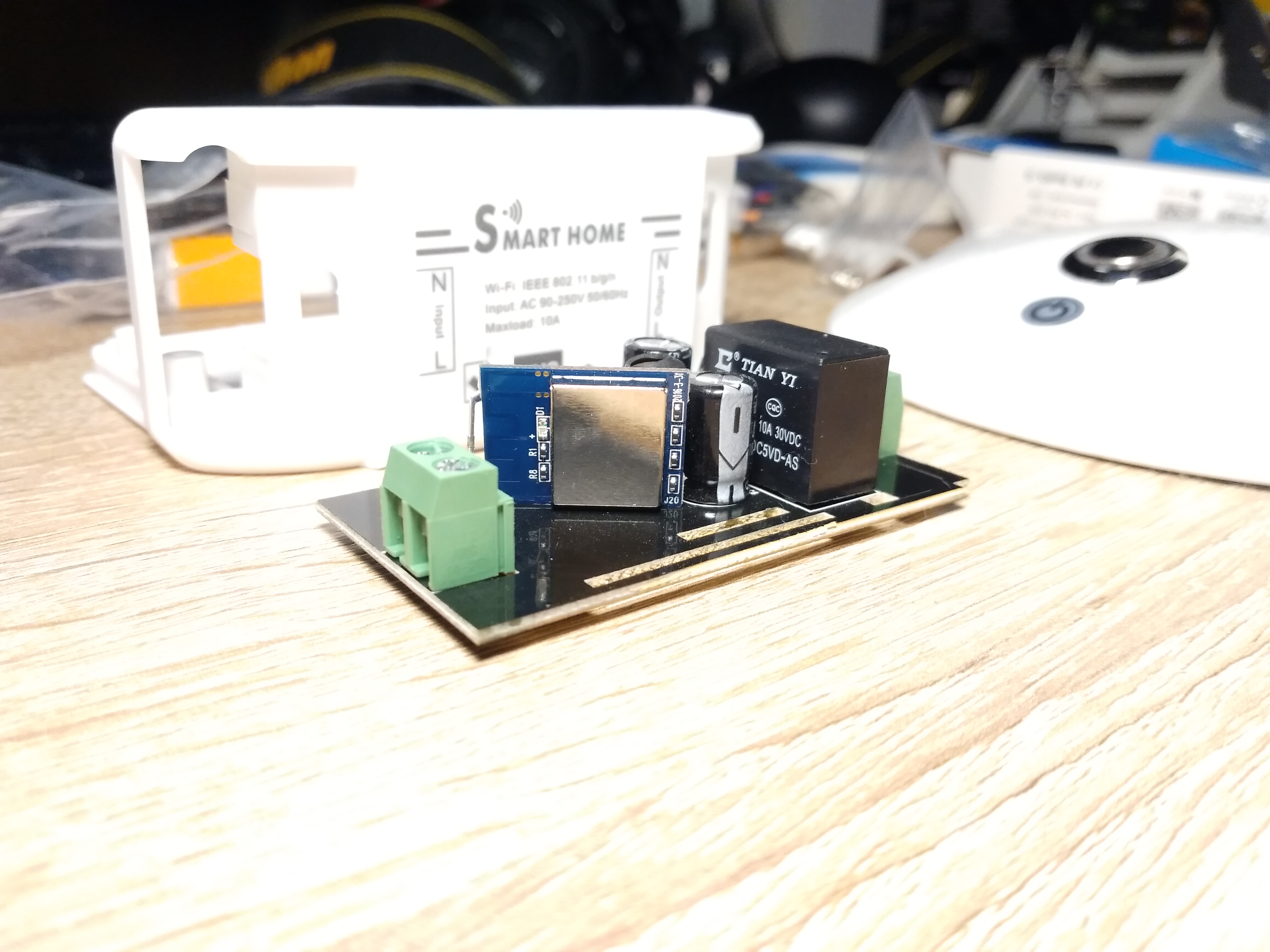
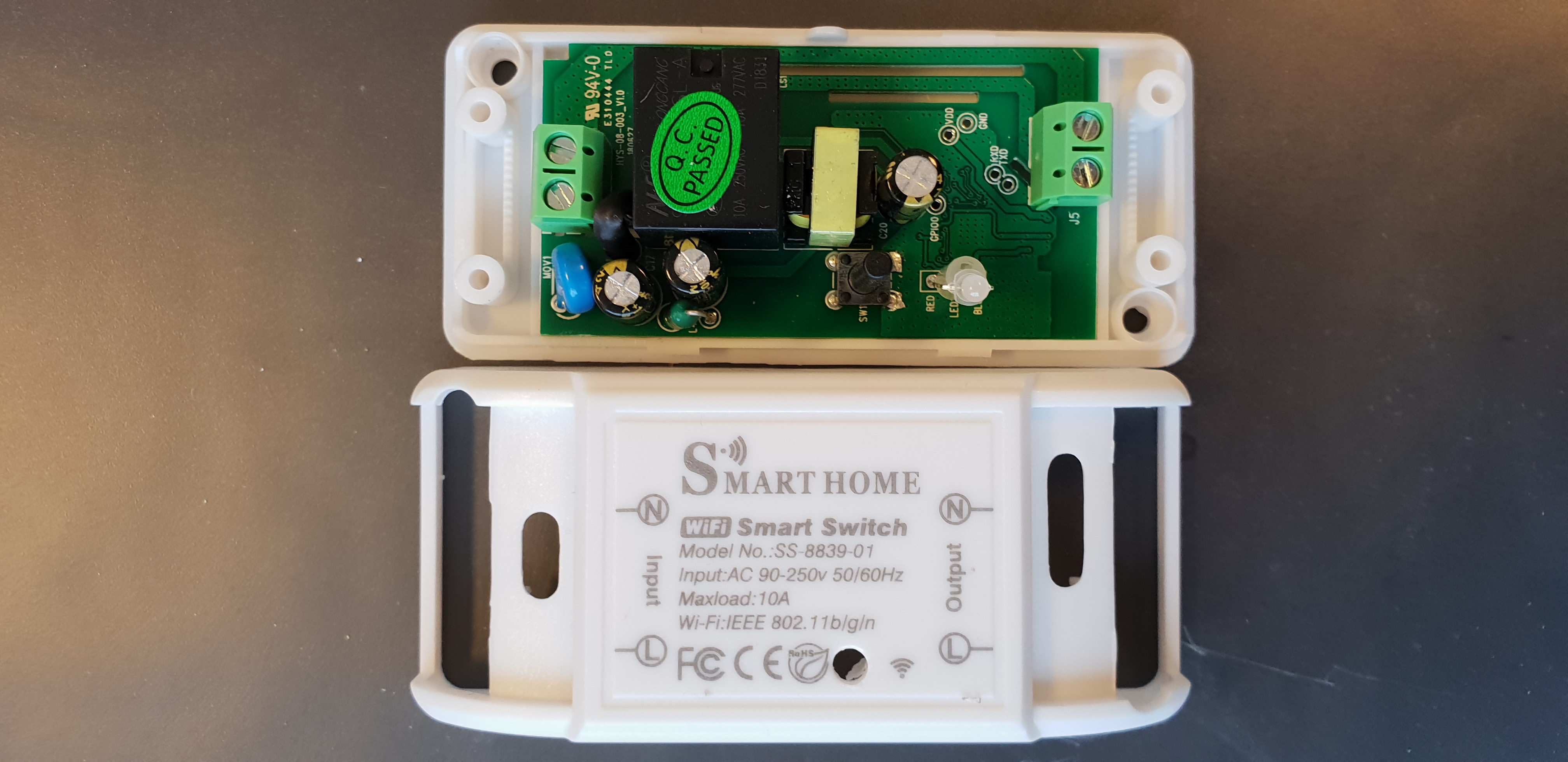
Hi,
finally I had a little bit of time to play around with the SMART HOME switch which is a clone of the Sonoff Basic, but with another chip.
See pinlayout on the following image...
Hope it helped!
Franky

Kiwifranky
on 17 Jan 2018
Hi again...
To make it work with TASMOTA:
Add
{"Smart Home", // Smart Home Switch (ESP8285 Sonoff Basic Clone)
0, 0, 0, 0,
GPIO_REL1, // GPIO04 Relais
0, 0, 0, 0, 0, 0, 0,
GPIO_KEY1, // GPIO12 Button on casing
GPIO_LED2, // GPIO13 Red Led
0,
GPIO_LED1, // GPIO15 Blue LED
0, 0}
into the sonoff_template.h ModuleTemplate collection and add "SMART_HOME" to SupportedModules enum and the nicelist.
Have a nice day....
Franky
Kiwifranky
on 18 Jan 2018
this does not work for me.
Can someone confirm the pinout ?
Could not flash Tasmota
 Hepman
on 22 Jan 2018
Hepman
on 22 Jan 2018
Hi,
I just checked if I used another PlatformIO.Ini, but no... everything as usual.
I flashed mine using this setup but I also had to try 3 times to get it into flashmode by pulling down d0....
Frank
Kiwifranky
on 23 Jan 2018
Hi again,
just an idea by looking at the pinout... Maybe I have mixed RX and TX, I will check when I am back home....
Frank
Kiwifranky
on 23 Jan 2018
I habe tried to Switch rx/tx
That is not the Problem
Hepman
on 23 Jan 2018
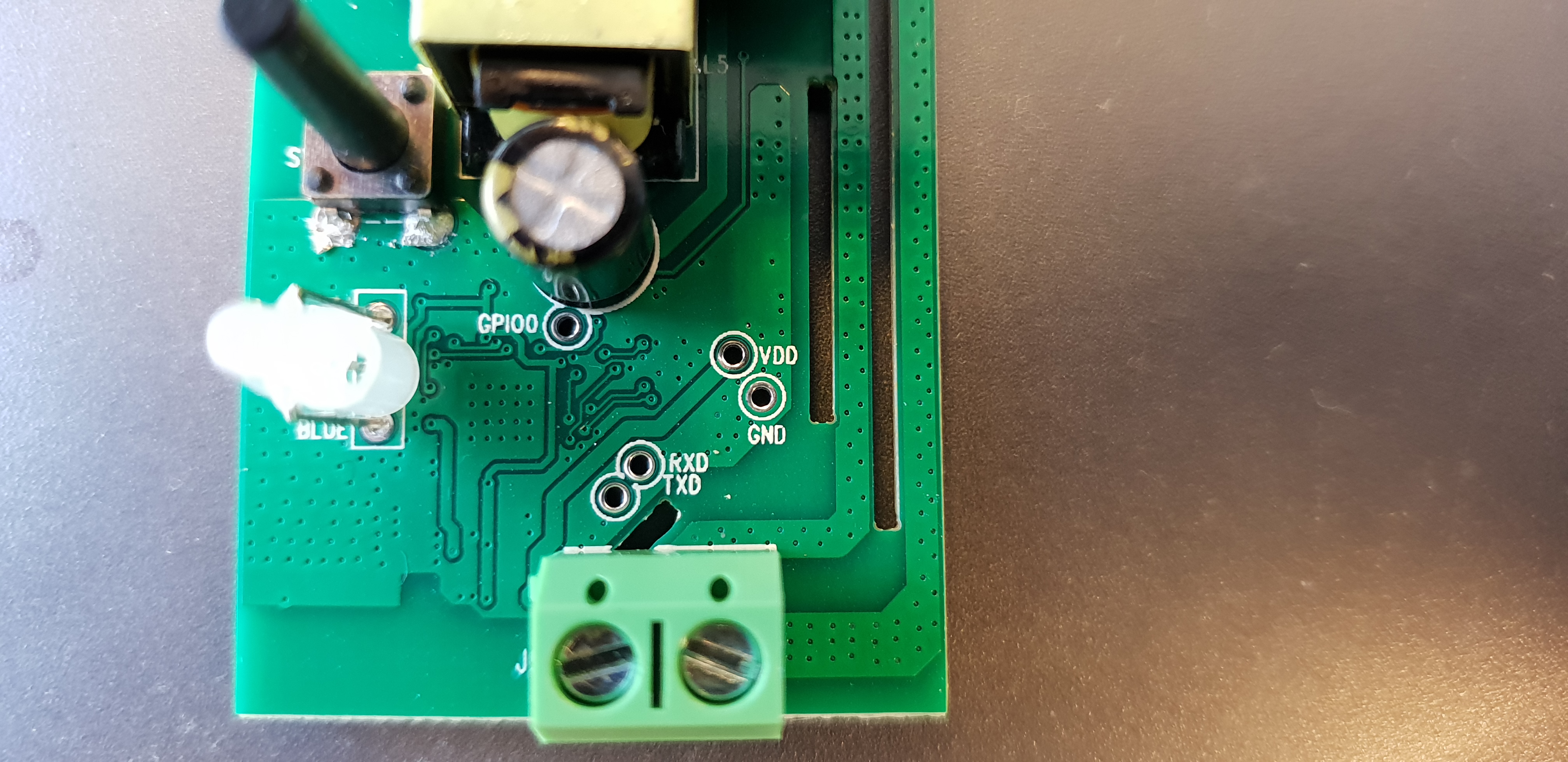
Hi again,
I reprogrammed mine today and everything worked fine (as expected).
The layout is OK!
If this is your first device to program at all....
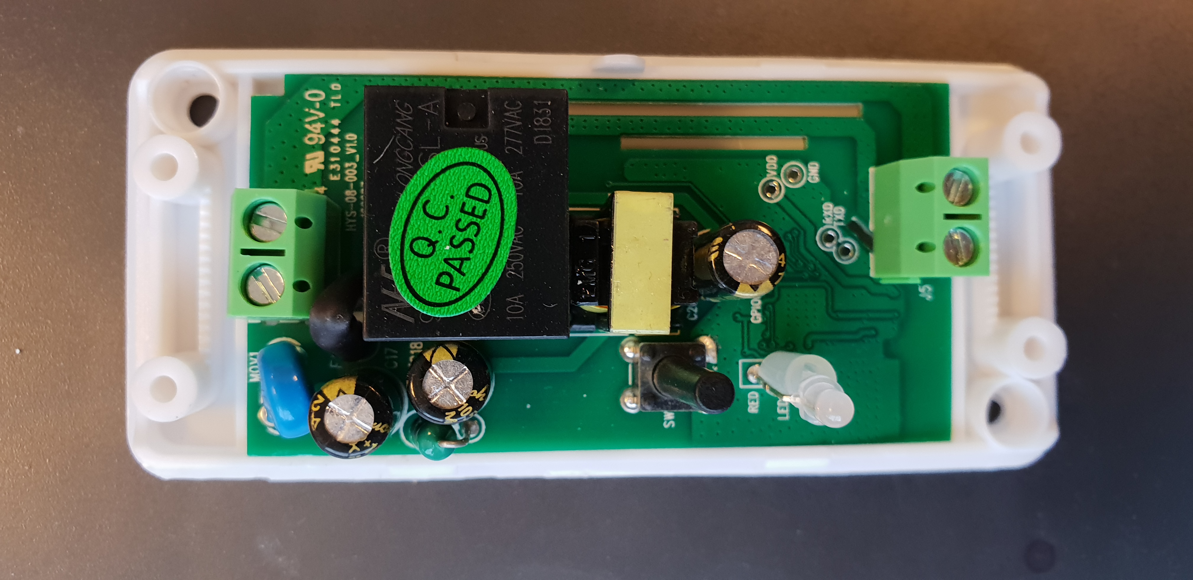
Here is the layout from the bottom side of the pcb:

You have to connect:
RX to the TX connector of your serial Interface
TX to the RX on the serial board
3V3 with the 3.3V Supply
GND with the Ground of your Supply
D0 has to be connected to GND while you power up the device
By the way: I am using Atom and PlatformIO for programming.
Kiwifranky
on 25 Jan 2018
Great work Kiwifranky. Can you submit a PR with your changes? This board is becoming more command and it would be nice to have this mainlined so future users could just grab a precompiled binary.
Perhaps this is a dumb question, but how are you connecting your serial device to the board for programming? I'll probably just solder on some jumper wires and connect to that, but if there's a better way to make temporary connection to the pads, I'd love to hear about it.
 Smoffitz
on 25 Jan 2018
Smoffitz
on 25 Jan 2018
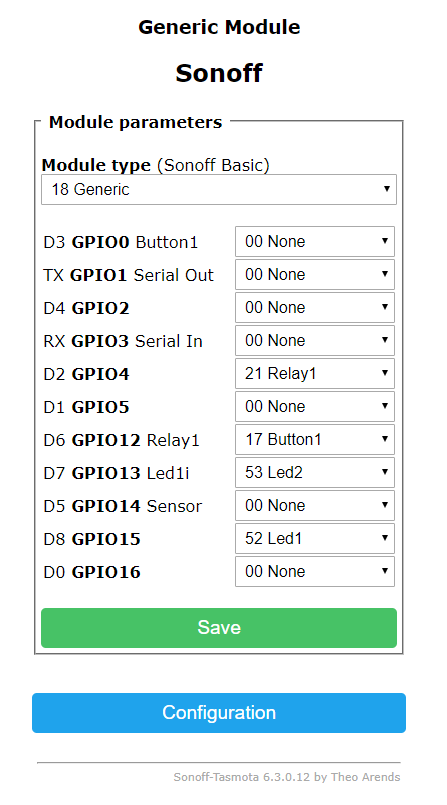
You can use the Generic Module to configure this, no need to patch and compile a special version:

Smoffitz
on 16 Apr 2018
This issue has been automatically marked as stale because it has not had recent activity. It will be closed if no further activity occurs. Thank you for your contributions.
![stale[bot] picture](https://avatars3.githubusercontent.com/in/1724?v=4&s=40) stale[bot]
on 5 Jun 2018
stale[bot]
on 5 Jun 2018
This issue will be auto-closed because there hasn't been any activity for a few months. Feel free to open a new one if you still experience this problem.
stale[bot]
on 20 Jun 2018
i can confirm this trick is working, but the "relay1" for me has 21 as number, not 17. Actually I don't really know what that number means, I followed a semantic matching scheme and everything was ok. Maybe it is because I did not add the lines inside sonoff_template.h , I leaved everything as git-cloned :-)
Here's my configuration
this was my purchase on amazon (italy) JamBer - Smarthome
https://www.amazon.it/gp/product/B07B6GMTR4
You can use the Generic Module to configure this, no need to patch and compile a special version:
 trigal
on 2 Dec 2018
trigal
on 2 Dec 2018
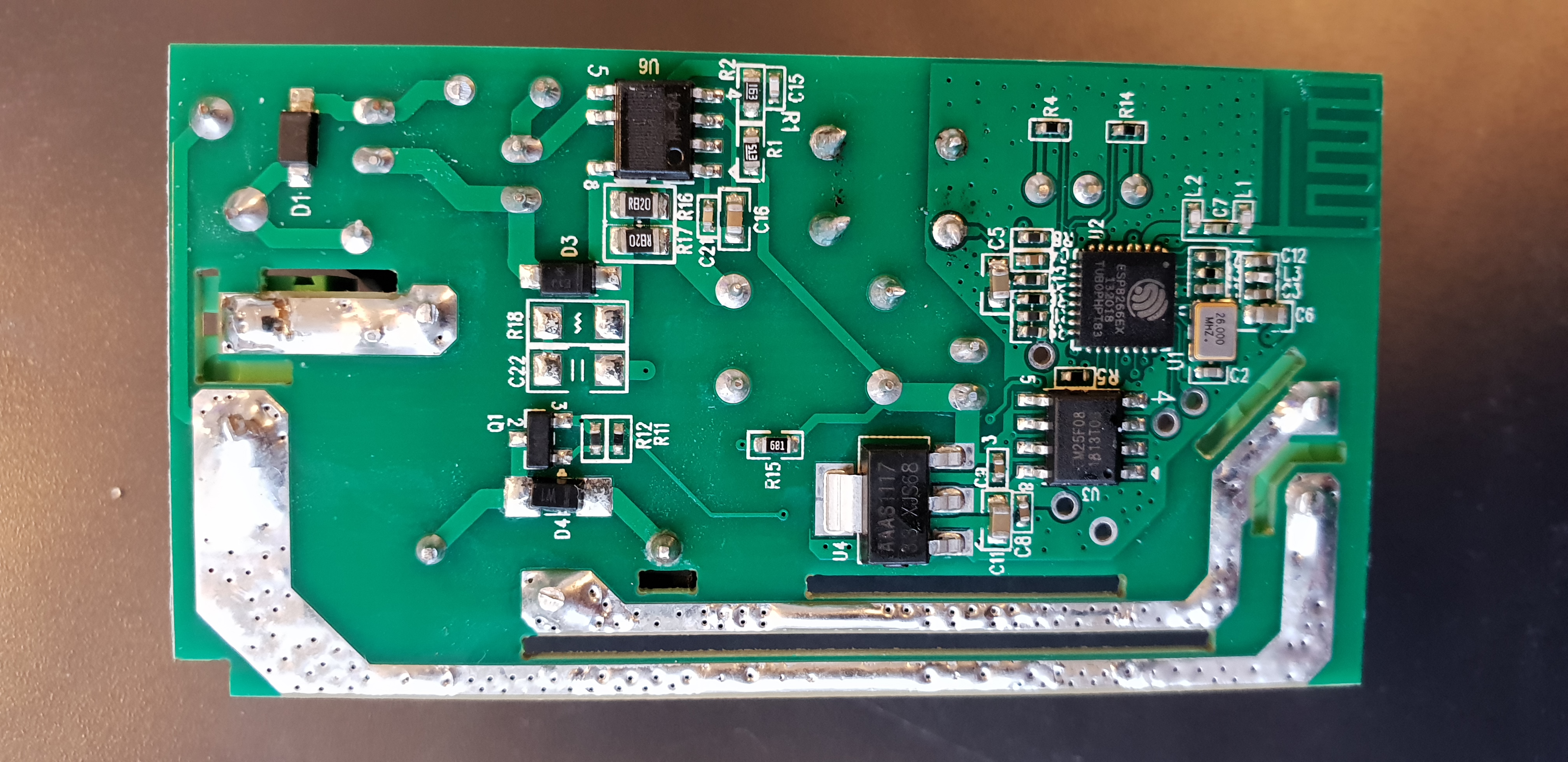
New(?) revision(version) SmartHome available.
Buyied from here: https://www.banggood.com/AC90-250V-WiFi-APP-Relay-Module-DIY-Smart-Home-Automation-Light-Switch-Work-With-Amazon-Alexa-Google-p-1351912.html?cur_warehouse=CN
Pins have to be soldered but they are labeled. To put it in the programming mode you have to shortcut GPIO0 and GND when powering on (3,3V). See photos.
I can confirm this revision also work with the settings from above.

 genuk
on 28 Jan 2019
genuk
on 28 Jan 2019
Hello
do you have a reddy projekt (file) that you can send me?
i will flash it with atom.
Thanks Thomas
 tbadde
on 27 Mar 2019
tbadde
on 27 Mar 2019
As genuk said above, it runs well with the UNEEDE Wifi Switch, too, which has the same Layout as the "Smart Breaker".
 ttrueten
on 19 Jul 2019
ttrueten
on 19 Jul 2019
Template published on the wiki.
{"NAME":"SmartHome Swit","GPIO":[255,255,255,255,21,255,255,255,17,57,255,56,255],"FLAG":15,"BASE":18}
Note that the two leds are inverted
 vzorglub
on 9 Aug 2019
vzorglub
on 9 Aug 2019
Related issues
 esp32x
·
3Comments
esp32x
·
3Comments
 luisfpinto
·
3Comments
luisfpinto
·
3Comments
 grizewald
·
3Comments
grizewald
·
3Comments
 TylerDurden23
·
3Comments
TylerDurden23
·
3Comments
 j4k3
·
3Comments
j4k3
·
3Comments
Most helpful comment
New(?) revision(version) SmartHome available.
Buyied from here: https://www.banggood.com/AC90-250V-WiFi-APP-Relay-Module-DIY-Smart-Home-Automation-Light-Switch-Work-With-Amazon-Alexa-Google-p-1351912.html?cur_warehouse=CN
Pins have to be soldered but they are labeled. To put it in the programming mode you have to shortcut GPIO0 and GND when powering on (3,3V). See photos.
I can confirm this revision also work with the settings from above.