Tasmota: 1 Channel Inching/Self-lockIing Mode WiFi Wireless Switch 5V/12V and Sonoff-Tasmota?
Hallo,
sorry i never posted anything on GitHub but I have a question and can't find a solution at this time. I'm a noob and like to control my Garage Door with Siri and Homebridge. My Garage Door needs a pulse to open/close.
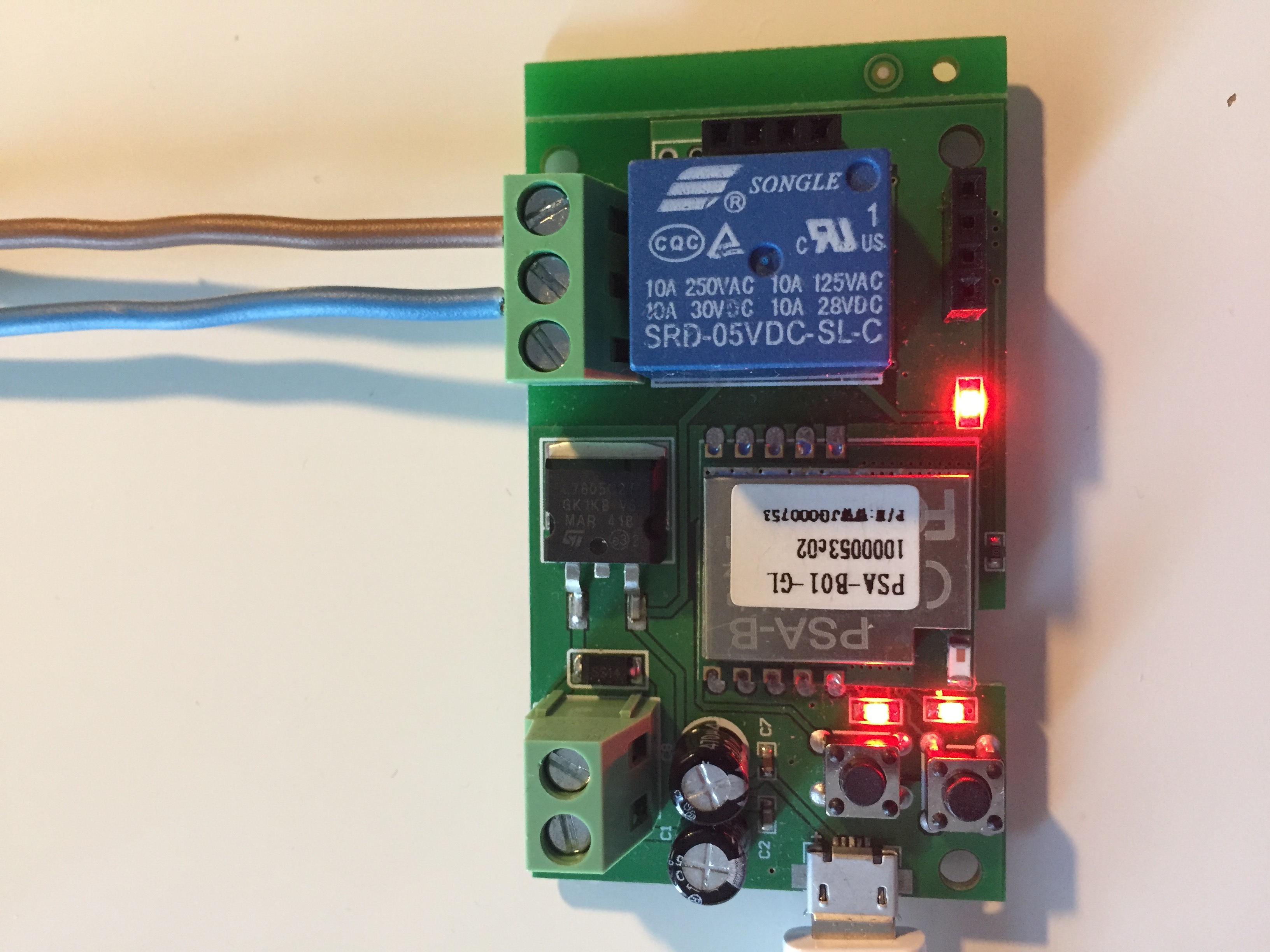
I bought the "1 Channel Inching/Self-lockIing Mode WiFi Wireless Switch 5V/12V" from itead.cc and like to use it with the Sonoff-Tasmota Firmware to connect via plugin to Homebridge.
Pictures of the Relay:
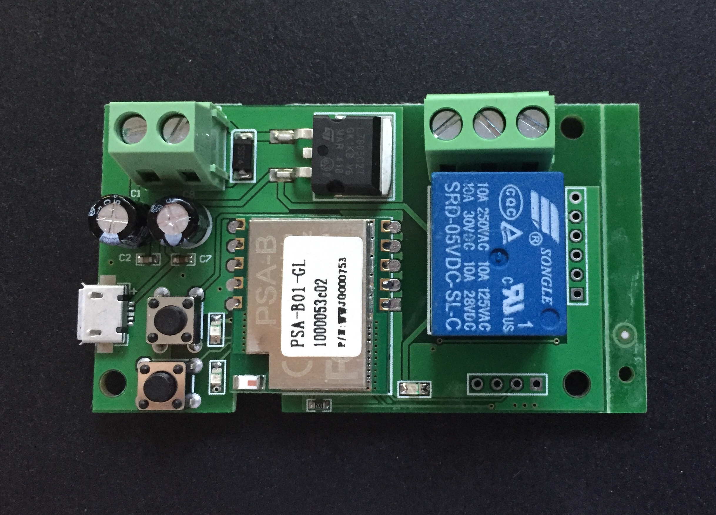

Is it possible to flash the Sonoff-Tasmota Firmware to this relay?
Where do i have to connect my USB adapter or can i just use the build in USB Port?
Where are the RX, TX, GIO Ports on this Relay?
I hope anybody can help me and sorry for my bad english.
Thanks!
 jannnfe
All 86 comments
You can use Tasmota.
Connect the FTDI to the 4 pin cconector near the relay
One of 2 black buttons must be GPIO0
 ionciubotaru
on 21 Sep 2017
ionciubotaru
on 21 Sep 2017
Thank you for your reply.
Is this right in the picture?

After the flash is the Self-lockIing Mode still working?
Thanks!
jannnfe
on 21 Sep 2017
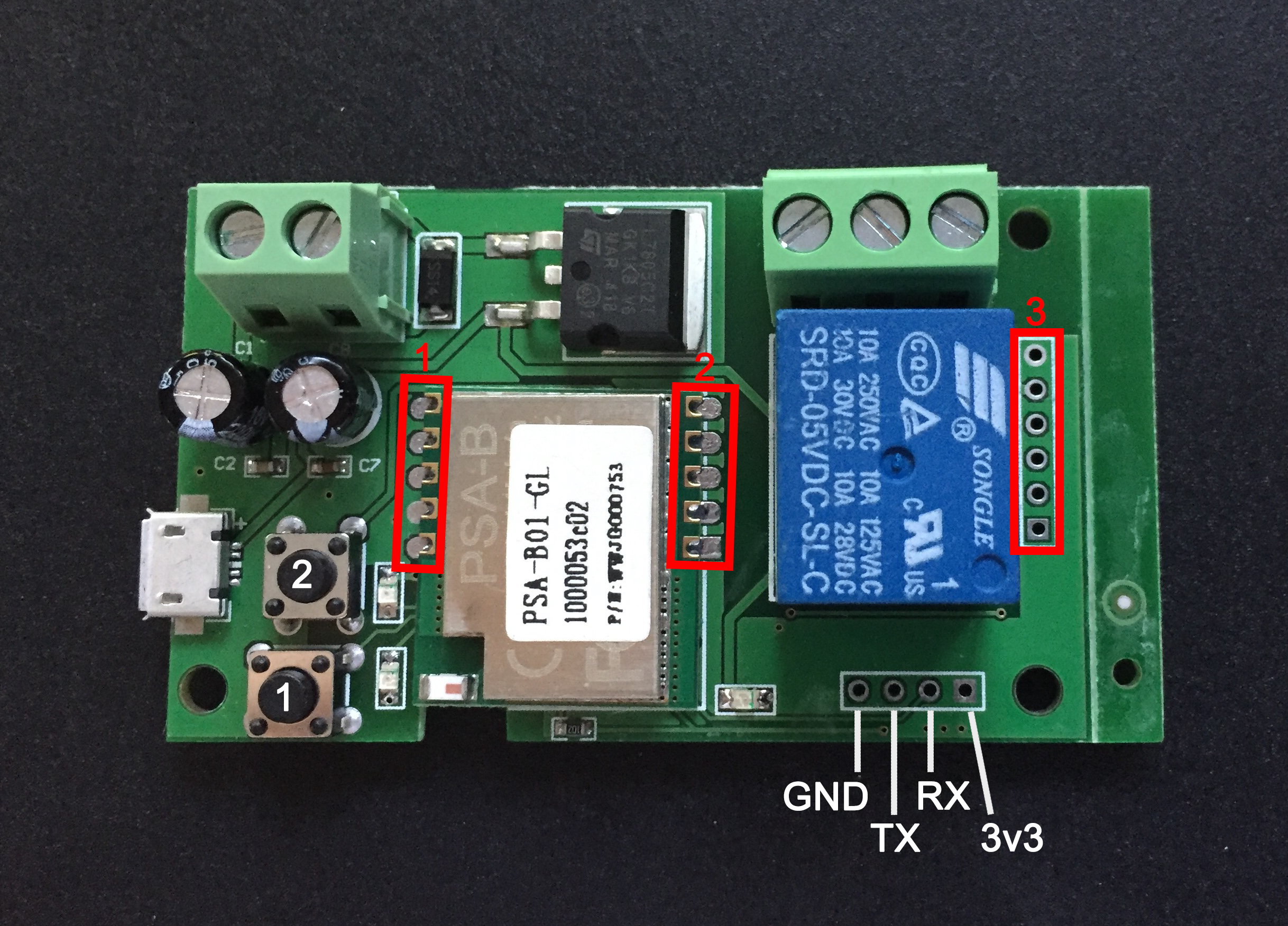
From left to right:
GND - TX - RX - 3V3
The square is 3V3
ionciubotaru
on 21 Sep 2017
Thanks!
I wrote with the itead.cc Support and they told me this device can not be flashing.
Is this right?
jannnfe
on 21 Sep 2017
any updates ? i have almost the same board, same problem

 itsecasc
on 27 Sep 2017
itsecasc
on 27 Sep 2017
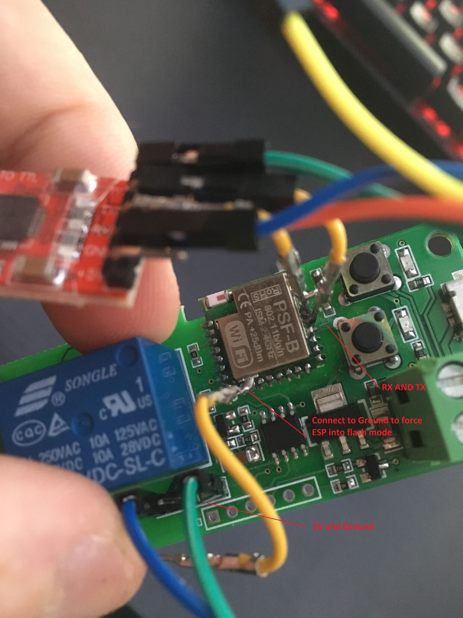
Hi, my board does not have connected RX and TX to the chip, so I must used wires with needles and connect directly to the chip. TX and RX is 2nd and 3rd from to left corner. And be aware about changed 3,3 and gnd pin!!!!! First connect 3,3 and gnd and check without button presing if led go on. Fter that start with pressed button. Then press second button, to have both leds light on. Then you can flas with needles, I had so 70 trys, because my hand shaked a lot ;) P.S. I used autoclick with 20s delay to upload firmware ;)
 tomasroud
on 5 Oct 2017
tomasroud
on 5 Oct 2017
Here is the connect picture. That left to gpio0 is not necessary, button is working good. And for tx, rx use needles.
tomasroud
on 5 Oct 2017
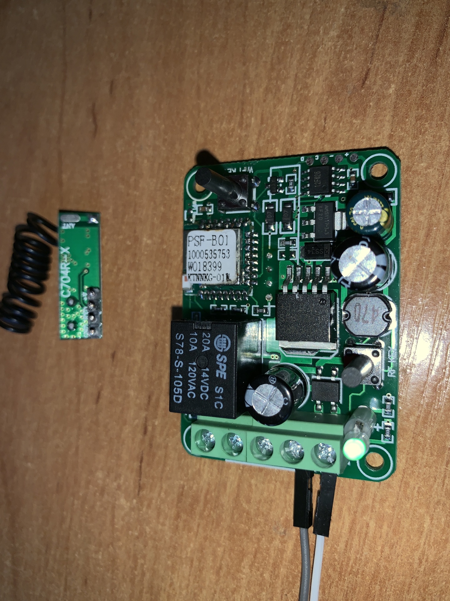
Related to @ionciubotaru must the occupancy look like this on my relay? (White):
@tomasroud you say it is possible to flash my relay? Does everything work the way it should or does complications occur?
Is the assignment at the top of the image or do I have to connect 3v3, RX, TX, GND in one of the three red rectangles? If yes, you can tell me which I must use and wich buttons when I must press. Many Thanks!
jannnfe
on 5 Oct 2017
Eat the elephant by pieces. First locate 3,3 + GND.
It should be GND and 3v3 as in your picture.
Try to connect if LED light up.
Got it? Next step.
Start flash mode ... must both of two LEDs light up.
Next step.
Locate TX + RX.
Try RX and TX on your picture .... try swap TX + RX.
Still not working.
Try on rectangle nr 1 second and third from bottom.
And again try to swap second and third as TX + RX.
Tell how successfull you are. And be aware about switch 3,3 and GND. If you connect bad gnd to 3,3 and connect TX or RX, you just demage your USB programmer. As I twice :(
tomasroud
on 5 Oct 2017
@tomasroud Now i have tested that what you are explaining.
I found out, that this picture is the right assignment:
But i don't know how to come in flash mode. Can you tell me?
EDIT: Now when i connect the 3v3 and GND no light flash on the Sonoff...
About 1 hour ago it was working. Whats wrong?
jannnfe
on 6 Oct 2017
Press one button nr. 1 or 2, try it and then connect to usb. If lights only 1 led, press next button till both of leds light.
Tell me, how it works.
P.S. When you connect 3,3 and GND, it will be too at bottom two pins on block nr. 3
tomasroud
on 7 Oct 2017
I use the same arrangement as at the beginning. In the beginning lights still lit. For some reason now lights nothing more when I connect via USB. I do not think this is broken. Can be connected where else GND RX TX and 3v3?
With the normal build in USB of the Sonoff it works perfectly. So the Board is not broken
jannnfe
on 8 Oct 2017
3,3 and GND are bottom 2 pins in block nr. 3, try it there, if the board will live. Try with ohmmetter that these pins are same as 3,3V and GND.
tomasroud
on 9 Oct 2017
@tomasroud No light on the block 3 :(
I think the usb adapter is broken but it is light up on usb connect and it gives out 3,3v.
jannnfe
on 11 Oct 2017
USB adapter can be broken on TX or RX, on 3,3 and GND probably not. So it must be OK.
If you connect GND and 3,3 is voltage on block 3, bottom 2 pins?
tomasroud
on 11 Oct 2017

Here are TX and RX pins, as I wrote above.
Picture source here: https://github.com/arendst/Sonoff-Tasmota/wiki/Hardware-Preparation
tomasroud
on 11 Oct 2017
Idk if this is stupid but i connected 3,3v on board voltage and GND, RX, TX like this picture
and now my mac recognize the board. The two light next to button 1 and 2 are flashing but in Arduino IDE 1.8.4 and 1.8.5 i get the same error like here: https://github.com/arendst/Sonoff-Tasmota/issues/957
jannnfe
on 12 Oct 2017
The board lives, that is cool, so, you should connect your USB adaptor to USB in pc in same time as btn. is pressed. Then both LEDs will light ... not flash, light still. OK? P.S. That error means TX or RX is not connected or board is not in fllashing mode (2 LEDs light still)
tomasroud
on 12 Oct 2017
So I have now tried all sorts of combinations and pins and with nothing I can flash the Tasmota firmware. I have two pictures where you can see the LED light up. No idea what the flash mode is and if he is even in flash mode. Any ideas on how to connect to the tasmota firmware?

jannnfe
on 31 Oct 2017
You must flash with VCC and GND from USB in PINS only. I see you have connected main voltage, it is not possible to flash the device like that. Unplug micro USB voltage, connect voltage in pins and tell me, if you can set up both these pictures too.
tomasroud
on 3 Nov 2017
I'm not able to get in this light mode on picture 2 with VCC and GND connected :(
jannnfe
on 4 Nov 2017
Press btn1 when connected to USB and release. Then press btn 2. IT MUST STAY IN 2 LEDs light on.
tomasroud
on 4 Nov 2017
No it don't work. I think I have a Version of the Sonoff, that is not flash able :(
jannnfe
on 8 Nov 2017
I am wondered, but maybe it is possible. I am sorry, that I can not help you :(
tomasroud
on 10 Nov 2017
This is how flashing mode should look like: https://www.youtube.com/watch?v=E0WBoFCcnYY
 ciotlosm
on 19 Dec 2017
ciotlosm
on 19 Dec 2017
Thank you for the Video. I can access this mode like in the video but im not able to flash the sonoff.
My Module ist the PSA-B01-GL
jannnfe
on 19 Dec 2017
Got it finally working!!!
I used Arduino IDE with ESP8285 and Flash Size : 1M (512k SPIFFS) and the latest Sonoff Firmware.
I connect VCC and GND to the pins shown above in the Photo and connect TX and RX (yellow and white cable) to the Pins shown in this picture

Hold the jumper cable to this pins without soldering it should work. Try swap TX and RX if its not working. After flashing you have to connect the USB to get into webinterface
For Mac check FTDI Drivers: https://github.com/esp8266/Arduino/issues/3711
jannnfe
on 19 Dec 2017
Sucsesfull flashed this with SonOTA
 badigit
on 11 Jan 2018
badigit
on 11 Jan 2018
Yesssss also!!! but which device belongs in the configuration set?
That's not the basic model
https://www.youtube.com/watch?v=wSjzj-Imj0c

 benjaminsonnleitner
on 12 Jan 2018
benjaminsonnleitner
on 12 Jan 2018
Try to use 1 Channel (option 12)
ciotlosm
on 12 Jan 2018
Now I have bought a new 1 channel module, which looks different again than what I had before. Since I already gained some experience, I was able to flash this module directly on the chip with RX and TX.
This Module:
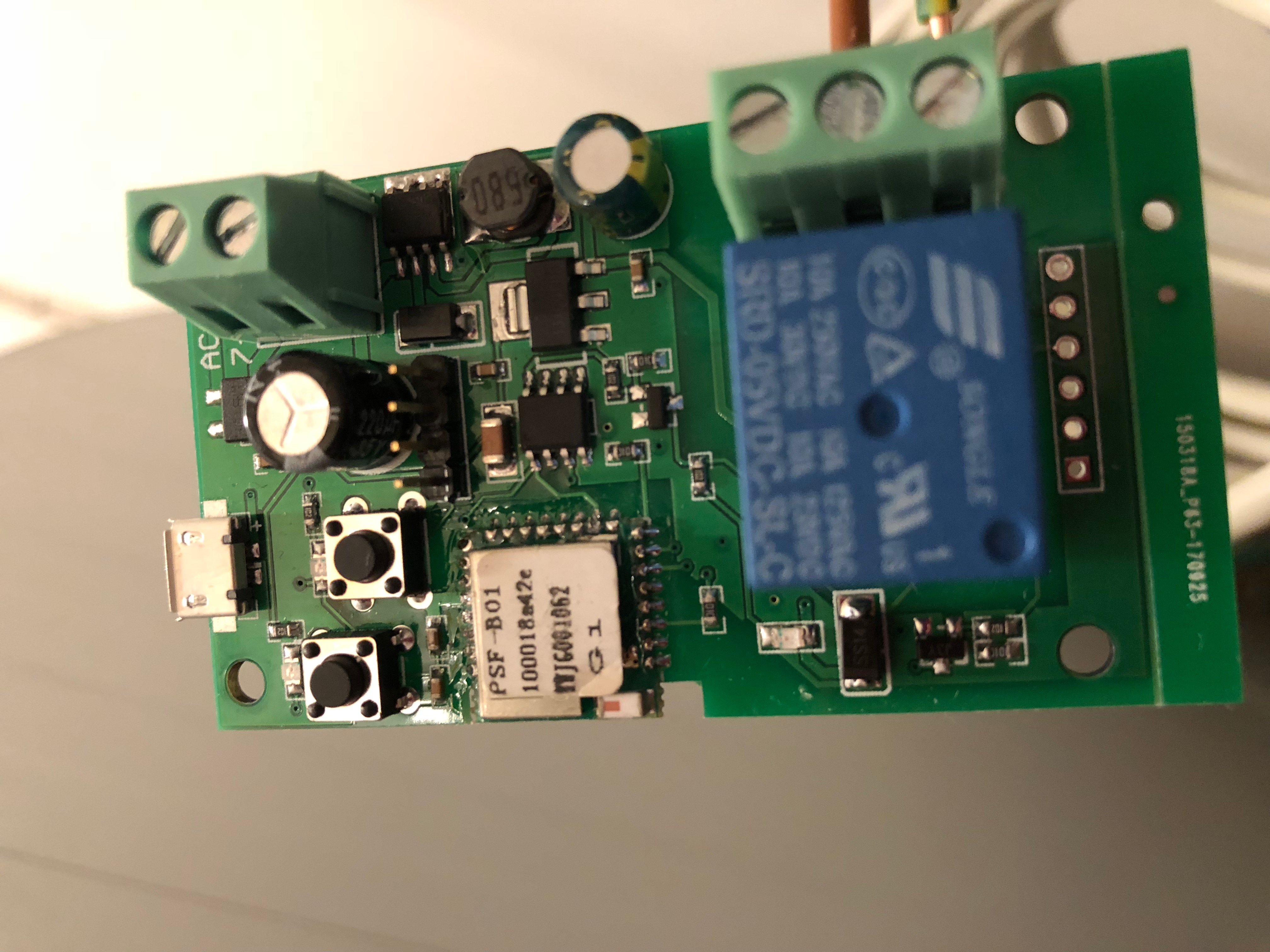
However, I'm wondering now. Is there any GPIO on this module that you can connect a reed sensor, for example, or do I have to solder directly to the chip?
I found this by @LurchiStromberg in this Issue about the PSF-B01 Chip:

Is there an easy to reach GPIO or RX TX on this module?
Thanks!
jannnfe
on 14 Jan 2018
Hey all,
please can you write any tutorial to flash and upload Tasmota firmware to 5V/12V relay?
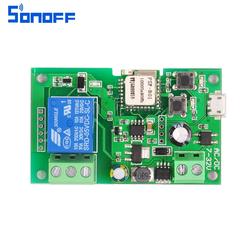
I have right this type:
I am using FTDI 3.3v. GND and 3v3 connection is correct but everytime when i try to upload Tasmota i get an error:
Uploading .pioenvssonofffirmware.bin
warning: espcomm_sync failed
error: espcomm_open failed
error: espcomm_upload_mem failed
I also tried swap TX and RX but it did not help.
Thanks
 budisek
on 18 Jan 2018
budisek
on 18 Jan 2018
@budisek You need to connect tx and rx to the PSF-B01 correct pins. I have a video that has some details that might help: https://www.youtube.com/watch?v=vzoM4op60jo
ciotlosm
on 18 Jan 2018
This Module is "hard" to flash.
- Set Up Arduino IDE: https://github.com/arendst/Sonoff-Tasmota/wiki/Arduino-IDE
- Connect the Jumper Cables to this Sonoff:

- Get into flashing Mode: Connect 3.3V while pressing both buttons and than press the bottom one like in this video: https://www.youtube.com/watch?v=E0WBoFCcnYY
- Upload Tasmota Firmware with PulseTime enabled
You can just hold the jumper cables at the chip pins seen in this video: https://www.youtube.com/watch?v=vzoM4op60jo
jannnfe
on 18 Jan 2018
Great thats look not so difficult.
Two questions:
In youtube video is used 5V or 3.3V mode?
And how can i enable pulsetime?
Thanks
budisek
on 18 Jan 2018
@budisek in my video I used USB 5.5V and used FTDI for ground/tx and rx only.
ciotlosm
on 18 Jan 2018
Hallo!
I doesn‘t Flash the module with FTDI...... I flashed over the Wifi with my MacBook our Windows .... its very easy .... Time what I needed: 2Minutes to Flash. Preparation: 15 minutes
benjaminsonnleitner
on 18 Jan 2018
I did it. I flashed it by cables and Tasmota is online.
But I need to set the relay to 1 sec ON and then OFF. I changed this in firmware before uploading:
define APP_PULSETIME 10
But it works strange. When I toggle ON, it crashes (led is blinking) and restart is necessary.
What I need to set the relay to ON for 1 sec?
budisek
on 18 Jan 2018
One time i had the same issue.
Its because Tasmota is not supporting the inching /Self-locking function of the module.
Maybe you are in the wrong mode. Press the Buttons and test different states.
I also pressed the buttons and at some point it worked.
You can change PulseTime by typing "PulseTime 30" in the Console at the Webinterface.
jannnfe
on 18 Jan 2018
You are right. I switched mode with second button. Then it works like switch (switching between ON and OFF manually) but when i changed pulsetime, now it is ON only for adjusted time. Great.
Last question i hope:
Is it possible to set power on state to OFF always? I see that with every restart it turns ON for short time (less than 1sec) before it toggles to OFF. You know, i dont want to have the garage door opened after every restart :)
budisek
on 18 Jan 2018
Really the restart issue is strange. I don't have this problem.
I changed nothing in the user_config.h except PulseTime, Project Name and Wifi Options and my module is always off even after restart.
Did you configure MQTT? I think I've heard that some functions work better when an MQTT broker is configured.
Maybe someone else knows better about this issue.
jannnfe
on 19 Jan 2018
In fact, i don't have relay connected to garage door yet, so I am only guessing now.
After every restart red LED (which blinks when I toggle ON) shortly lights and relay clicks twice. Maybe it is some part of restart and it will have no effect to opening. I will let you know.
Thanks for your help.
budisek
on 19 Jan 2018
You can do the firmware update OTA without touching the module.
https://haus-automatisierung.com/hardware/sonoff/2018/01/04/sonoff-vorstellung-part-11.html
The video is in german, but you can copy the commands.
 Alpengroove
on 22 Jan 2018
Alpengroove
on 22 Jan 2018
Dear All,
Does anywone can tell me where I find the GPIO14 on this board? would be great
Rik
 Reikard80
on 23 Jan 2018
Reikard80
on 23 Jan 2018
@Reikard80 have a look at this picture. You will find it directly on the Chip
I found this by @LurchiStromberg in this Issue about the PSF-B01 Chip:
EDIT: @Alpengroove this link is dead :/
jannnfe
on 23 Jan 2018
Hi Jannnfe,
Thanks a lot, indeed now I found gpio14 :) thanks for your support on this
Rik
Reikard80
on 23 Jan 2018
Wont this 5/12v work without flashing for garage door ? why is flashing necessary ?
help the lost soul please.
 salmanslim
on 24 Feb 2018
salmanslim
on 24 Feb 2018
It will work but if you can get it flashed it will support an input like a reed switch to determine if your door is open or closed if you are not in line of sight of door.
Doug
 Bull10X
on 8 Mar 2018
Bull10X
on 8 Mar 2018
How do I flash with pulsetime? And what is pulsetime?
I do have adruino ide setup and able to flash tasmota to sonoff basic without any problem.
Thanks
 sumasage
on 21 Mar 2018
sumasage
on 21 Mar 2018
I have it working with tasmota. But how I add a reed switch to it? Thanks
 tuga49
on 24 Mar 2018
tuga49
on 24 Mar 2018
@tuga49 - Did you get this figured out? I am trying to do the same thing.
 rmarkle
on 2 May 2018
rmarkle
on 2 May 2018
I am using it wothout flashing as i am using a smartthings sensor for open/close notifications.
salmanslim
on 2 May 2018
@salmanslim - thank you.
All,
I can't seem to get the PSF-B01 GPIO14 pin to recognize the reed switch. Evertime the switch is closed, it fires off the relay. The console shows the same. Any Help?
rmarkle
on 9 May 2018
This issue has been automatically marked as stale because it has not had recent activity. It will be closed if no further activity occurs. Thank you for your contributions.
![stale[bot] picture](https://avatars3.githubusercontent.com/in/1724?v=4&s=40) stale[bot]
on 23 Jun 2018
stale[bot]
on 23 Jun 2018
This issue will be auto-closed because there hasn't been any activity for a few months. Feel free to open a new one if you still experience this problem.
stale[bot]
on 8 Jul 2018
This Module is "hard" to flash.
1. Set Up Arduino IDE: https://github.com/arendst/Sonoff-Tasmota/wiki/Arduino-IDE 2. Connect the Jumper Cables to this Sonoff:  3. Get into flashing Mode: Connect 3.3V while pressing both buttons and than press the bottom one like in this video: https://www.youtube.com/watch?v=E0WBoFCcnYY 4. Upload Tasmota Firmware with PulseTime enabledYou can just hold the jumper cables at the chip pins seen in this video: https://www.youtube.com/watch?v=vzoM4op60jo
This board is marked with 7-32 AC/DC. Is it safe to power it up with AC power?
 gadLinux
on 24 Nov 2018
gadLinux
on 24 Nov 2018
This board is marked with 7-32 AC/DC. Is it safe to power it up with AC power?
Only if the AC is between 7 and 32 volts. I have mine powered by my door intercom transformer which is around 16-18v AC
 Martin-Dolan
on 28 Dec 2018
Martin-Dolan
on 28 Dec 2018
Hello
I ordered a similar WiFi module on Aliexpress.
https://www.aliexpress.com/item/Wifi-Remote-Switch-1CH-AC-DC-7-36V-10A-Smart-Home-Relay-Module-433Mhz-Receiver-Support/32902426871.html?spm=a2g0s.9042311.0.0.74185c0fkrwS6E
My one has an RF module, besides it seems very similar to Sonoff RF. Of course, it has ewelink software. I would like to reprogram it on tasmote, but I do not know how to enter it in flashing mode. Maybe someone was already trying to flash it? Will you help me?
 mientki
on 31 Dec 2018
mientki
on 31 Dec 2018
It will be the same as the other modules. Power it on while holding gpi0 to ground for a few seconds
Martin-Dolan
on 7 Jan 2019
Hello everyone , i am totally new on git , this board is very useful for me and i want to use this board with my own android application . I would be great full if some can help me find the android sdk for this board .
 udayroy04
on 27 Feb 2019
udayroy04
on 27 Feb 2019
You are right. I switched mode with second button. Then it works like switch (switching between ON and OFF manually) but when i changed pulsetime, now it is ON only for adjusted time. Great.
Last question i hope:
Is it possible to set power on state to OFF always? I see that with every restart it turns ON for short time (less than 1sec) before it toggles to OFF. You know, i dont want to have the garage door opened after every restart :)
Have same problem. After soft-restart in webui, relay switch 1-0.
After hard-restart (via power onoff) - no problems, relay stay off
badigit
on 3 Mar 2019
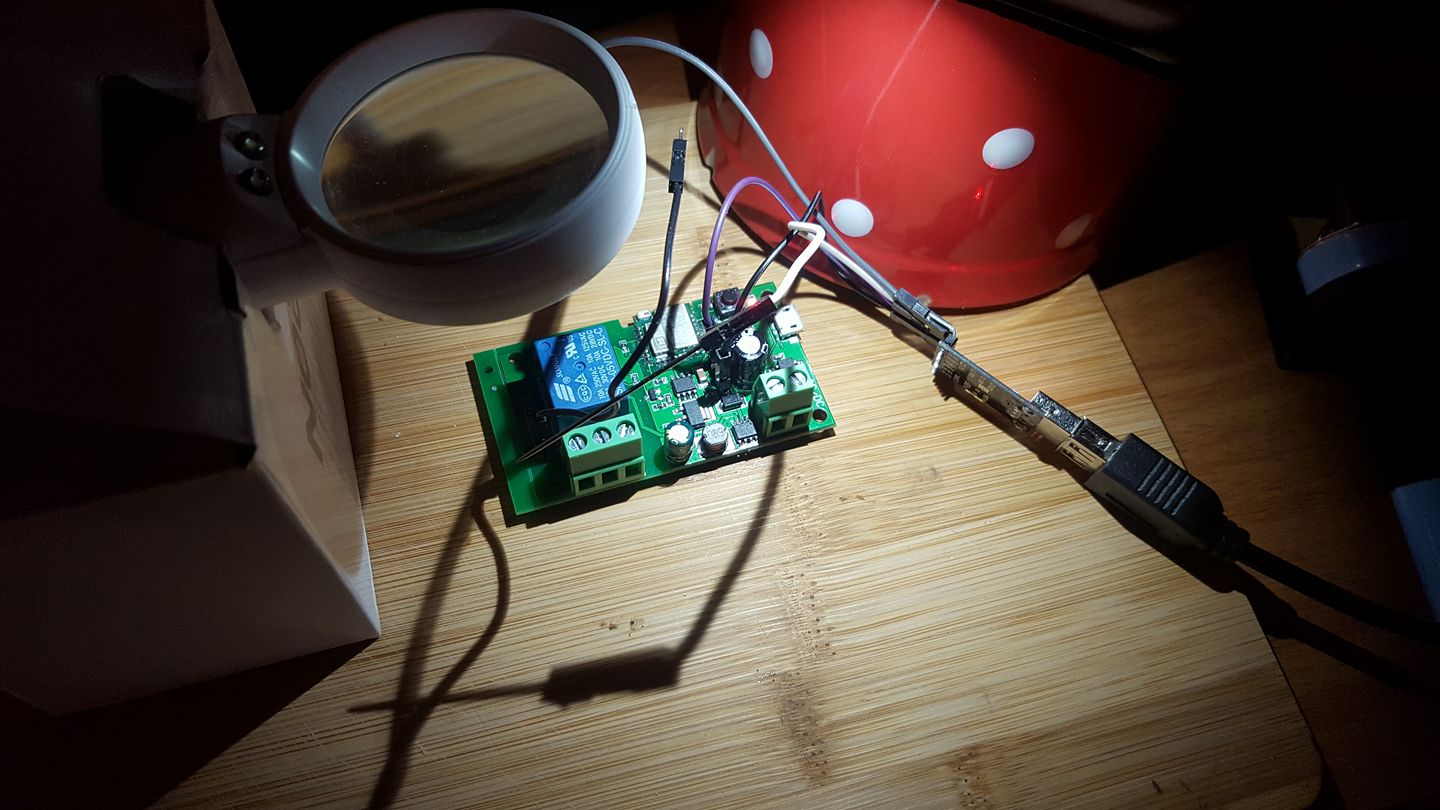
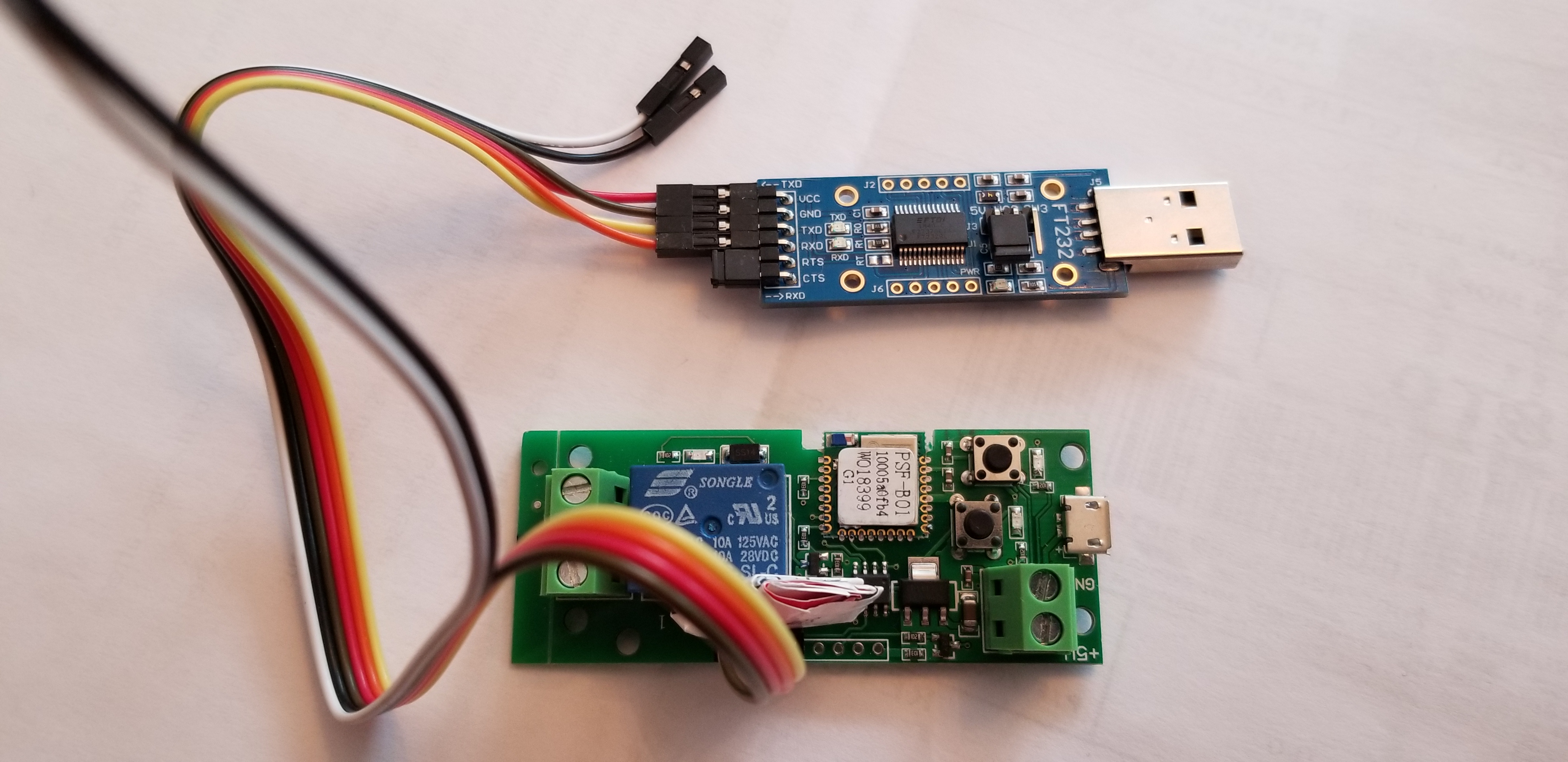
hello, please can anyone help me, I have tried every possible combination of wires and button holds as I power on, I am using ESP easy, lol. The Sonoff device is a 1 channel inching type, the serial device is a DSD tech FT232 TTL. I have looked for pin outs for the serial device and can not find, I have tried with the jumper on the RTS and CTS pins and without. I have tried 5v and 3.3V jumpers, I do not think I fried anything yet but the serial board did get a bit hot at first. Everything still seems to light up and at least is not completely dead yet, not even sure which button to hold down so I have tried both seperately. Please see the picture showing 2 boards, I get flash failed every time, so it at least attempts to connect. Orange and yellow are TX and RX, Red is +, brown is ground.


 Bacon-Ranch
on 6 Apr 2019
Bacon-Ranch
on 6 Apr 2019
Eat the elephant by pieces. First locate 3,3 + GND.
It should be GND and 3v3 as in your picture.
Try to connect if LED light up.
Got it? Next step.
Start flash mode ... must both of two LEDs light up.
Next step.
Locate TX + RX.
Try RX and TX on your picture .... try swap TX + RX.
Still not working.
Try on rectangle nr 1 second and third from bottom.
And again try to swap second and third as TX + RX.
Tell how successfull you are. And be aware about switch 3,3 and GND. If you connect bad gnd to 3,3 and connect TX or RX, you just demage your USB programmer. As I twice :(
was your USB programmer obviously dead? Just wondering if I messed mine up, it is still seen by Windows, powers up, shows a TX light, but is not flashing the Sonoff inching device.
Bacon-Ranch
on 6 Apr 2019
Have same problem. After soft-restart in webui, relay switch 1-0.
After hard-restart (via power onoff) - no problems, relay stay off
Absolutely the same behavior. Any workaround?
 scasic
on 12 Apr 2019
scasic
on 12 Apr 2019
I wanted to reopen this (it can be immediately reclosed) JUST because I know of no other place to post this valuable information, and in my pursuit of the information I found no other place online where it is properly discussed!!
Here is how to flash your PSF-B01.
NO HARDWARE MODIFICATIONS ARE NECESSARY.
(Note I have the AC/DC 7-32V module and I will be using it as a thermostat override to power on my HVAC fan using Tasmota/HA. This process should work fine for the other version of this module too.)
Use this pinout;
Use this flash boot method (press both buttons while powering it. Both LEDs need to come on.
You can flash Tasmota now.
Once booted, set it to module "1 channel (12)" in the included module list (no external template is needed).
VERY IMPORTANT
SetOption13 1
This will disable the "triple press" functionality that usually reboots ESP8266 into SmartConfig Mode.
After that, you can select via the hardware button if you want inching or locking latch, and you are good to go!
I hope this message saves someone A LOT of time. I took me quite a while to figure out why the module was going haywire.
 ryaske
on 3 Nov 2019
ryaske
on 3 Nov 2019
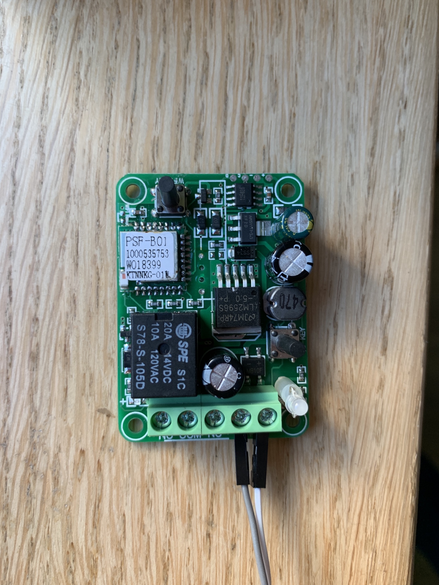
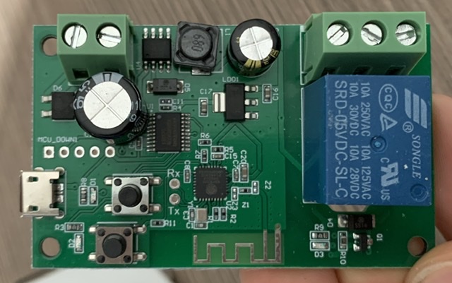
hi, I have this Relay. Rx and Tx are evident.
3v3 and Gnd I don't know where they are. Can someone help me? Thanks.
 leonraul
on 14 Nov 2019
leonraul
on 14 Nov 2019
Can someone help me? Thanks.
To teach a man to fish ...
here's what you do. Look up the labeling on the ESP chip (or any of the others), and see their pinout. That's how you can follow where power is coming in
To fish for a man......(happy to save you the time)
LD01-- that is your 3.3 volt regulator. to be absolutely certain I would want to know the labeling on that device so you can verify the pinout, but I am 90% certain that the large metal contact (near label C17) is going to be your 3.3v output(along with one of the three legs, probably the middle one from my experience with thse regulators). So grab your multimeter, stick the black lead onto the casing of that USB connector (we can assume that iwll be ground across the board), Plug a USB cable in, and probe both that big contact and the little one in the middle of the three. If you get 3.3v , follow that to a convenient place to solder or just connect to the small tab temporarily(what i'd do).
Ground is even easier to find--- it will also be one of the three LD01 legs. From the photo I'd bet its the closest to the bottom.. .and connecting to the ground plane. You can use your meter to find 3.3v between your now-known 3.3v pin on that device and one of the other two small legs. You can just connect the ground right onto that chip too (with your 3.3v FTDI. If you are using a 5 volt you'll want to connect the 5v to U4 instead). Highly recommend you verify your measurements match the pinout datasheet, just to double check yourself.
Hope this helps!!
You may already know, but you also need to get the ESP chip into boot mode, which may require grounding of some of the GPIOs. Try it by just using the GPIO0 button held during boot, first. If that doesnt work you may wnat to look up the pinout of the particual ESP you have on there and see what it needs. I have seen ones that ned more than GPIO0 ... like 15(?) also grounded at boot. It also depends what is wired to it on the board itself (I had to cut a trace and then repair it later to get it to flash).
You shouldnt have much trouble finding this info out there in the web! Let us know if yo uneed more assist
ryaske
on 14 Nov 2019
Thanks! You were really kind. I tried to measure but the multimeter marks zero. The chip is an ESP8285. I'm probably doing something wrong.

leonraul
on 15 Nov 2019
Thanks! You were really kind. I tried to measure but the multimeter marks zero. The chip is an ESP8285. I'm probably doing something wrong.
Ok then that may be ground (and I stand corrected!!). Or maybe the USB outer casing isnt actually board-wide ground.
Next, measure between two of the three smaller pins... all three combinations one at a time
(make sure you are in DC volts mode and not OHMs.. and DONT short any pins accidentally!)
Do you measure any voltage there? You sohuld see 5v and 3.3v there. You really have to, or maybe your meter is broken or not set correctly (or else the board wouldn't power up at all ---- as both the ESP8285 and the LED you see there are powered with 3.3v that must originate from that regulator chip--- whether you power the board with USB or with an outside voltage source, it still comes from there.)
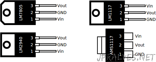
If still having an issue, use another multimeter. And can you make out the labeling on that regulator? If it is AMS1117 its the same chip I use for all my custom made ESP projects..... (and the same one I've seen on sonoffs). Its pinout is always this (bottom right). INPUT will be 5v in this case, OUTPUT is 3.3v
ryaske
on 15 Nov 2019
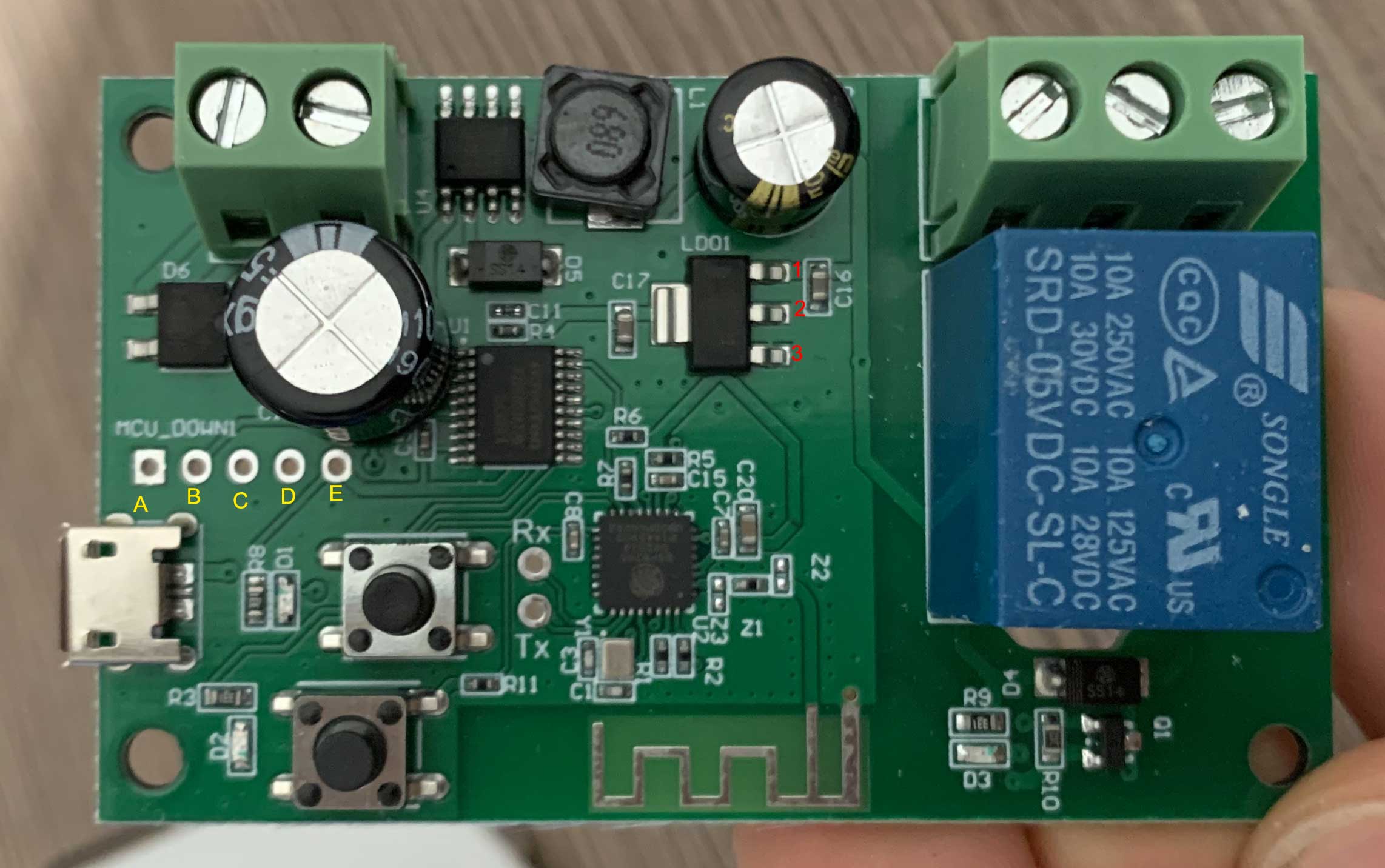
I confirm! It's an AMS 1117. The GND is pin number 3 of my photo.
3--->1 =5v
3--->2=3.3v
3--->A=0
3--->B=3.3v
3--->C=0
3--->D=0
3--->E=3.3v
A--->1=5v
A--->2=3.3v
Can I therefore say that A is the GND and B is 3.3v?
leonraul
on 15 Nov 2019
Well, 1= 5v, 2= 3.3v and 3= ground. This matches the pinout I posted above (but you are using numbers in reverse, nbd).
With that said, I would be cautious about assuming anything about ABCDE. Not sure you are certain that one of those is not just "pulled high" by the ESP chip, or if it is actually tied to pin 2. Same for the 0v readings, is it connected to GPIO and just pulled low at the time you're measuring, or actually tied to ground? Cant be sure of that from what you tested so far
What you would do to verify that is either--- break out a bagnifying glass and very carefully follow the traces from the pin #2. Does it go to A B C D or E?
Yoiu could also flip your multimeter into continuity mode (it either makes a beep or reads 0ohms when both probes are touched together), make sure your board is unpowered, and probe pin 2. Do you get zero ohms to any of the letter pads? If so, and you can see a trace that goes direct between the two-- only then would I say you are good to use the letter pads. Otherwise, just tack a wire onto pin 2 for your 3.3v+ and pin 3 for your ground. Those we are certain about already!
Though, A def seems like a ground pad. The square pad itself tells us that too.
ryaske
on 15 Nov 2019
Ok. I set the multimeter to continuity mode.
I use the inverted numbering of my photo
A--->3 =Beep (1 and 2 No)
B--->3=Beep (1 and 2 No)
C--->3 =Beep (1 and 2 No)
D--->3=Beep (1 and 2 No)
E--->2 =Beep (1 No)
E--->3=Beep
A= Gnd and E =3,3v?
leonraul
on 15 Nov 2019
hi, I have this Relay. Rx and Tx are evident.
3v3 and Gnd I don't know where they are. Can someone help me? Thanks.
Where you ever able to get this board in flash mode? I for the life of me can't get it to boot in flash mode.
I have tried the button hold down method, and when that didn't work I assumed they aren't connected to GIO0, so I tried grounding what I believe to be the GIO0 pin on the esp itself
 carl689
on 12 Dec 2019
carl689
on 12 Dec 2019
To the future person googling for this board using the previous mentioned numbering scheme
Ground - A
3.5V - E
Rx - TX
Tx - Rx
Important: To fix flashing being unstable add a capacitor to 2,3
Hold down the button closest to the Rx/Tx when you boot up, Tada
carl689
on 13 Dec 2019
To the future person googling for this board using the previously mentioned numbering scheme
Ground - A
3.5V - E
Rx - TX
Tx - RxImportant: To fix flashing being unstable add a capacitor to 2,3
Hold down the button closest to the Rx/Tx when you boot up, Tada
Thank you for making me gain valuable time! I installed HAA and currently using one of these as door electric strike relay
 istefanpop
on 21 Dec 2019
istefanpop
on 21 Dec 2019
Thank you for your value information.
Please help me with this board.
I don't know exactly where are Ground, 3v3 and gpio?

 thienvlkt
on 24 Dec 2019
thienvlkt
on 24 Dec 2019
Hi, can you help me?
thienvlkt
on 1 Jan 2020
@thienvlkt
Please address this to the Tasmota Support Discord Chat. The chat is a better and more dynamic channel for helping you. Github issues are best used for Tasmota _software feature requests and bug reporting_. Troubleshooting and setup assistance is more effective using an interactive forum.
Please check the Contributing Guideline and Policy and the Support Guide.
Thanks.
Support Information
See Wiki for more information.
See Chat for more user experience.
See Community for forum.
See Code of Conduct
 meingraham
on 1 Jan 2020
meingraham
on 1 Jan 2020
Indeed, I received the same new version of this Sonoff and was able to flash it with Tasmota, after powering it on while pressing on both buttons. Below the connections:

 Denis-tls
on 6 Jan 2020
Denis-tls
on 6 Jan 2020
Last question i hope:
Is it possible to set power on state to OFF always? I see that with every restart it turns ON for short time (less than 1sec) before it toggles to OFF. You know, i dont want to have the garage door opened after every restart :)Have same problem. After soft-restart in webui, relay switch 1-0.
After hard-restart (via power onoff) - no problems, relay stay off
Absolutely the same behavior. Any workaround?
 tasict
on 26 Jan 2020
tasict
on 26 Jan 2020
Anyone figure out the solution to prevent the relay from switching on when performing a soft reset?
I noticed that it also does this behavior when wifi disconnects, this is a big problem
 jeremylee7
on 1 Mar 2020
jeremylee7
on 1 Mar 2020
Indeed, I received the same new version of this Sonoff and was able to flash it with Tasmota, after powering it on while pressing on both buttons. Below the connections:
Thanks mate! i installed tosmota on my chip also, it looks the same, but the RX and TX were vice versa.
 blade3609
on 26 Mar 2020
blade3609
on 26 Mar 2020
Indeed, I received the same new version of this Sonoff and was able to flash it with Tasmota, after powering it on while pressing on both buttons. Below the connections:
Thanks for your info, saved me a lot of time. To make it even easier for others:
- You have to push both buttons during the whole process. I used some clothespins for this.
- Firmware I used was Sonoff basic 6.6. I tried 7.1.2 before but that didn't work and I had to flush again. But maybe I did something wrong.
- Configuration is Sonoff RF.
I updated to 7.1.2 via the web UI and it worked. So don't know what happened before...
 foobar26
on 6 Jun 2020
foobar26
on 6 Jun 2020
Hello guys, i need some help. There's not output tension after relay in my sonoff. I measured with multimeter and nothing change. Can someone help me? Thanks


 patrikpandolfi
on 30 Jun 2020
patrikpandolfi
on 30 Jun 2020
Secondary Pins of the relais don't have any connection. You have to connect any external power to com. This will be switched from NO to NC
 2lepus
on 6 Aug 2020
2lepus
on 6 Aug 2020
Hi,
I have the same relais as @patrikpandolfi flashed with tasmota.
How can I reset this one without access to the device website?
 jhartlep
on 21 Dec 2020
jhartlep
on 21 Dec 2020
Related issues
 Ndrinta
·
3Comments
Ndrinta
·
3Comments
 ximonline
·
3Comments
ximonline
·
3Comments
 Vujagig
·
3Comments
Vujagig
·
3Comments
 esp32x
·
3Comments
esp32x
·
3Comments
 kckepz
·
3Comments
kckepz
·
3Comments
Most helpful comment
I wanted to reopen this (it can be immediately reclosed) JUST because I know of no other place to post this valuable information, and in my pursuit of the information I found no other place online where it is properly discussed!!
Here is how to flash your PSF-B01.
NO HARDWARE MODIFICATIONS ARE NECESSARY.
(Note I have the AC/DC 7-32V module and I will be using it as a thermostat override to power on my HVAC fan using Tasmota/HA. This process should work fine for the other version of this module too.)
Use this pinout;

Use this flash boot method (press both buttons while powering it. Both LEDs need to come on.
You can flash Tasmota now.
Once booted, set it to module "1 channel (12)" in the included module list (no external template is needed).
VERY IMPORTANT
SetOption13 1
This will disable the "triple press" functionality that usually reboots ESP8266 into SmartConfig Mode.
After that, you can select via the hardware button if you want inching or locking latch, and you are good to go!
I hope this message saves someone A LOT of time. I took me quite a while to figure out why the module was going haywire.