Tasmota: Open/flash Sonoff B1 Light Bulb
just got one, but I can't access the serial connection pins yet.
at least without breaking something.
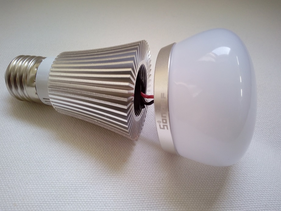
the base seem to contain the power regulator, everything else is in the top.
it can be unscrewed from the big heat-sink but that doesn't help because the 2 parts are still attached to one another via the cable.
to access the electronic the plastic cover has to be removed. has anyone successfully accomplished that without breaking it?
once I accomplish that, I'd like to help testing the tasmota firmware for the B1
 qorron
All 90 comments
Yes. I open B1 Bulb.
I use my work gloves and twist plastic led clover and pull one side and cover pop out.
Maybe i can help testing tasmota firmware on that Bulb.
 mredone
on 2 Aug 2017
mredone
on 2 Aug 2017

Where can i find a pinout/layout? How can we control the lamp?
I flash the 5.5.0, but :( ......
 timtimsson
on 4 Aug 2017
timtimsson
on 4 Aug 2017
@timtimsson I understand that you managed to flash the device with Tasmota v5.5.0. What happens if you select module Sonoff LED? Are you able to control both white LEDs? Do not expect color LED control as it has not been built into Tasmota yet.
 arendst
on 5 Aug 2017
arendst
on 5 Aug 2017
@arendst ...yes i use the Sonoff Led Modul, but nothing :(
: Color FF00, FFFF, 00FF + Power ON + Dimmer 100
we need the layout....
if i flash my own dump back, it works again with ewelink....
timtimsson
on 5 Aug 2017

timtimsson
on 11 Aug 2017
@timtimsson It looks to be the correct schematics.
Controlling the my9231 will be my challenge...
My B1 is on it's way and should arrive anytime now.
arendst
on 11 Aug 2017
@arendst : my B1 has a 8285...
my9231 - maybe you can use library my9291?
timtimsson
on 12 Aug 2017
@timtimsson I just uploaded experimental support for Sonoff B1 in the development branch.
Please give it a try.
- Select Module Sonoff B1
- Change color with command Color RRGGBBCCWW so it needs 10 hexadecimal values. I'm not sure the leds are being controlled in the correct order (if any led is being controlled at all).
Hue support is not available yet.
TBC
arendst
on 12 Aug 2017
... 17:11:44 MQTT: /ESP_Bu1/stat/RESULT = {"POWER":"ON", "Dimmer":64, "Color":"A3A3A3A3A3"}
but nothing, all leds are dark....
timtimsson
on 12 Aug 2017
Pity. You'll have to wait for my B1 to arrive and I can do some testing.
BTW what is the result of color A300000000?
arendst
on 12 Aug 2017
17:24:24 CMND: color A300000000
17:24:24 MQTT: /ESP_Bu1/stat/RESULT = {"POWER":"ON", "Dimmer":63, "Color":"A000000000"}
- all leds dark....
timtimsson
on 12 Aug 2017
What if you enable interrupt control by removing the slashes in file xdrv_snfled.ino from lines 80, 118, 128 and 156?
arendst
on 12 Aug 2017
.. i remove all slashes: but nothing same result, dark...
17:33:59 CMND: color A300000000
17:33:59 MQTT: /ESP_Bu1/stat/RESULT = {"POWER":"ON", "Dimmer":63, "Color":"A000000000"}
i hope the circuit plan is not wrong - i receive it from sonoff direktly ???
timtimsson
on 12 Aug 2017
Again, pity.
Have to go. I'll try when I have mine.
arendst
on 12 Aug 2017
ok - thanks a lot...
timtimsson
on 12 Aug 2017
After I read this I have ordered a Sonoff B1...it takes normaly 20 Days and I hope tasmota is supported then
 FabianHM
on 12 Aug 2017
FabianHM
on 12 Aug 2017
Just made a new branch called Sonoff-B1 with some changes that might work on the bulb.
Pls give it a try.
Still waiting for mine to arrive.
arendst
on 13 Aug 2017
... {"StatusFWR":{"Program":"5.5.2d", "BuildDateTime":"2017-08-13T11:54:00", "Boot":6, "Core":"2_3_0", "SDK":"1.5.3(aec24ac9)"}}
CMND: color A300000000
MQTT: /ESP_Bu1/stat/RESULT = {"POWER":"ON", "Dimmer":63, "Color":"A000000000"}
... but nothing, everything is still dark :cry:
timtimsson
on 13 Aug 2017
Try color 0000A00000
arendst
on 13 Aug 2017
11:09:46 CMND: color 0000A00000
11:09:46 MQTT: /ESP_Bu1/stat/RESULT = {"POWER":"ON", "Dimmer":62, "Color":"00009E0000"}
...dark, no flickering nothing...
timtimsson
on 13 Aug 2017
Thnx for trying. Back to my shed...
arendst
on 13 Aug 2017
yes of course...If you have any ideas, please share it, i will test it again..
timtimsson
on 13 Aug 2017
Did update with another Module (Sonoff B1 b) using different GPIO pins (but seem to be more used with type of bulbs)
Pls give it a go.
arendst
on 13 Aug 2017
no, gpio 13,15 also doesn't work :(
i can't find my9231 on the top of my platine - how can i find the right pins?
timtimsson
on 13 Aug 2017
I've seen pictures where they were able to remove the platine from the shell and showed the power supply underneath. Perhaps if you are abvle to remove it too you can see underneath to see the my9231 or my9291 chip.
arendst
on 13 Aug 2017
pity, i can't remove the platine on the top with a screwdriver and the platine inside is coverd with a plastic tube....
if i remove the tube, i have no chance to isolete the platine after this, because the wire are on the back from the topside platine...

timtimsson
on 13 Aug 2017
Just leave it be. If I get mine I can experiment quicker with software parameters and hope to get it to work. In the meantime I'll be implementing the AiThinker RGBW light bulb too as it is almost using the same code what has been in the wild for some months now so that should work anyway.
Pause for now...
arendst
on 13 Aug 2017
ok...
timtimsson
on 13 Aug 2017
Received mine today. Made some progress:

Still not there although the schematics seems to be OK as I can control "some" led.
arendst
on 15 Aug 2017
Just uploaded (at least with me) working Sonoff B1 version in the Sonoff-B1 branch.
Pls give it a try.
arendst
on 15 Aug 2017
very very good! :sunglasses: :thumbsup: :heart_eyes:
timtimsson
on 17 Aug 2017
Hi. My gpio0 pad is broken. Can i find it anywhere?
mredone
on 17 Aug 2017
@mredone
maybe you can try this - i don't know:
if not, then take the gpio0 pin on the 8285 directly....

timtimsson
on 17 Aug 2017
Now i search for right leg on chip but i cant find clear photo with info where is gpio0
mredone
on 17 Aug 2017
@arendst
only a question: if i take the color slide in the middle {"POWER":"ON", "Dimmer":100, "Color":"0000007F7F"}, then is this not 100 -> FFFF is 100
but not so important for me, because i use mqtt
timtimsson
on 17 Aug 2017
@mredone
https://www.itead.cc/wiki/images/b/b5/0a-esp8285_datasheet_en.pdf
dot is left/up - gpio0 is bottom from right the 2nd...
timtimsson
on 17 Aug 2017
Code upload but b1 not start. No HTTP server. No logs via serial
mredone
on 17 Aug 2017
@mredone flash mode dout?
https://github.com/arendst/Sonoff-Tasmota/wiki/Theo's-Tasmota-Tips
arendst
on 17 Aug 2017
Damn. On 8266 i have DOUT. But when i chance to 8285 Arduino Ide not show that option. Damn!
mredone
on 17 Aug 2017
@mredone less damn as the esp8285 selection automatically selects dout but it might use the wrong linker file.
Why not stay at your esp8266 set to dout. Other than fixed dout there is no change in selecting esp8285 but changing the settings in the ide might default to settings you do not want.
Bottomline: always use esp8266 with flashmode dout and linker file 1M no spiffs.
arendst
on 17 Aug 2017
Can somebody post picture/instructions on where the header needs to be installed on the PCB?
 rajil
on 26 Aug 2017
rajil
on 26 Aug 2017
@arendst some pictures for the wiki would be quite helpful
 ThomDietrich
on 1 Sep 2017
ThomDietrich
on 1 Sep 2017
Today my B1 arrvied and I need help to open it.
How Can I open the acrylic cap?
Is the Cap fixed with a thread?
FabianHM
on 1 Sep 2017
screw it back on and pop it off with controlled brute Force.
just don't cycle the power 3 times in a row. because then the power supply fries.
qorron
on 1 Sep 2017
@qorron what do you mean by frying the power supply? :thinking: I'm going to get some B1 bulbs at some point and definitely don't want to fry them.
 richrd
on 3 Sep 2017
richrd
on 3 Sep 2017
The pads on this thing are small so soldering on this is difficult. I dont see any button so how do you put this into flash mode? Does anything needs to be connected to the GPIO pad?
My flash upload is simply failing now.
rajil
on 3 Sep 2017
Is it not possible to write the Tasmota firmware to the bulb which is connected to the network via "Over the Air"?
 HellfireZA
on 4 Sep 2017
HellfireZA
on 4 Sep 2017
Any guide how to flash the B1?
 ageorgios
on 7 Sep 2017
ageorgios
on 7 Sep 2017
I would like to know the same please, how do I flash the B1? Thanks :)
 badgerhome
on 9 Sep 2017
badgerhome
on 9 Sep 2017
a howto would be very helpful
 msth
on 12 Sep 2017
msth
on 12 Sep 2017
I've succesfullly flashed my Sonoff B1. It's just the same as with most sonoff devices, like the s20. Just connect the programmer to the 4 pins on the left. The only difference is that you need to connect the GPIO0 with the GND when attaching the FTDI USB-TTL programmer. After that you can disconnect those and upload your code.
 janvde
on 12 Sep 2017
janvde
on 12 Sep 2017
Could someone make a step by step or video please?
Thanks.
 eggfat
on 13 Sep 2017
eggfat
on 13 Sep 2017
you wobble pop up the top part of the bulb with controlled force
ageorgios
on 13 Sep 2017
It is amusing to follow this thread. Nowadays everyone has a smartphone with a camera and internet access with automatic cloud storage. How can it be such a fuzz to upload a picture so others can profit from ones experience!?
There are device specific articles in the Tasmota wiki (e.g. Sonoff Dual), it would be astonishing if someone could create such an article for the B1. I would do it myself if I had such a device.
ThomDietrich
on 13 Sep 2017
any ideas flashing the B1 without soldering?
ageorgios
on 13 Sep 2017
I don't solder wires to anything, I use spring loaded pogo pins and hold them in
place.
you can do the same thing with bare wire (as long as you have something large
enough to be reasonably stiff)
 davidelang
on 13 Sep 2017
davidelang
on 13 Sep 2017
Some people managed to use sonota with their devices. I don't know if the B1 would work though.
Take a look in the wiki regarding upload and follow the link to sonota.
It should allow for uploading tasmota from itead ewelink.
arendst
on 13 Sep 2017
When reading what @janvde said, in regards to the fifth pin. I don't understand... slightly vague there, you say connect the GPIO0 with the GND, do you mean that there's one cable coming from the FTDI GND pin that splits into 2 connections to the bulb, 1 for GPIO0 and 1 for GND resulting in 5 points of contact on the bulb but only 4 pins being used on the FTDI?
HellfireZA
on 15 Sep 2017
I don't own a B1 myself but from what I've read so far the method should be like follows. If someone could please confirm that, this thread can finally be put to sleep.
Just as for most other modules you need to connect the FTDI programmer just as explained under: https://github.com/arendst/Sonoff-Tasmota/wiki/Hardware-Preparation#serial-connection
Additionally one needs to connect GPIO0 with ground during power up. That is described here: https://github.com/arendst/Sonoff-Tasmota/wiki/Hardware-Preparation#bringing-the-module-in-flash-mode
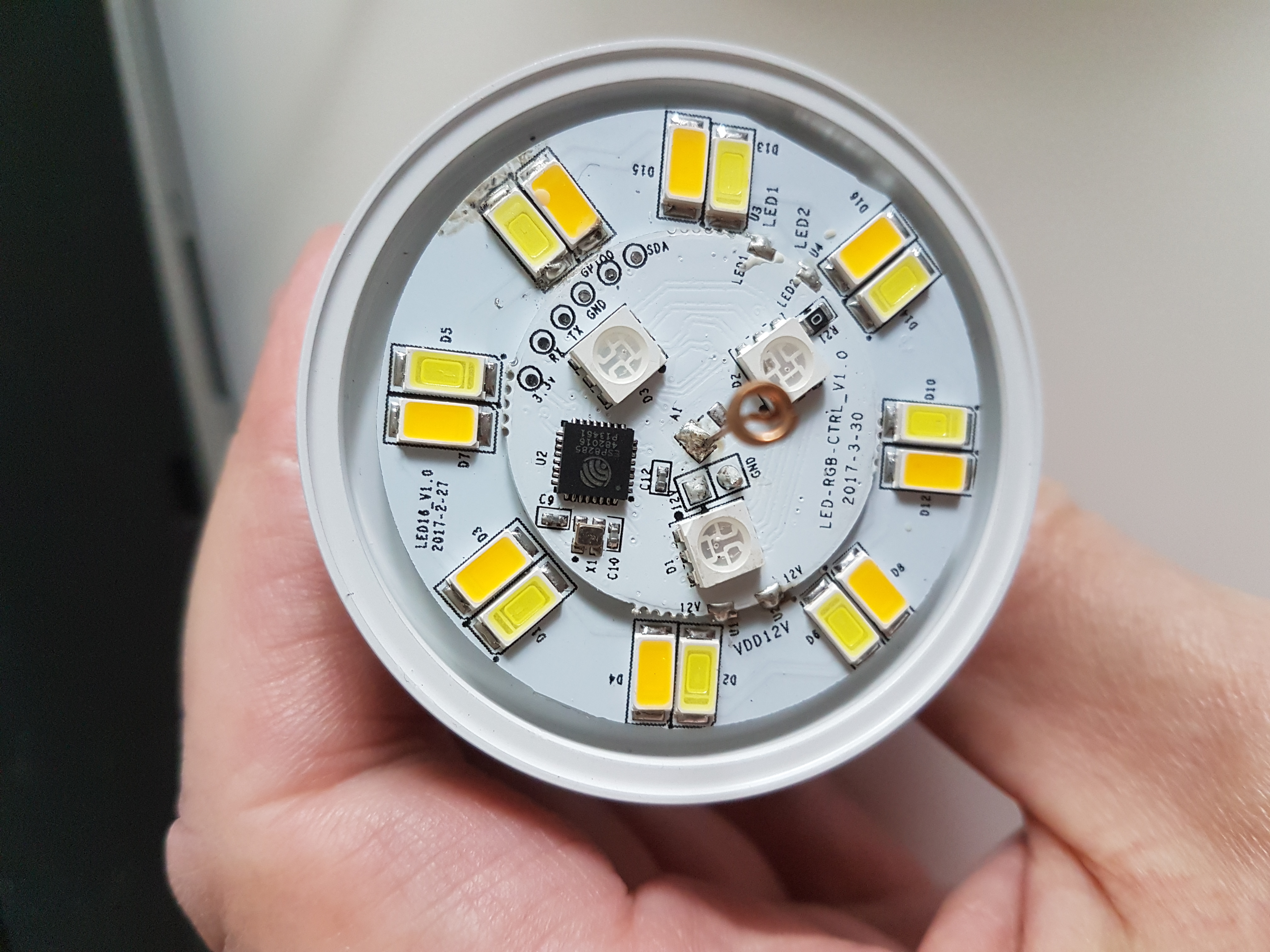
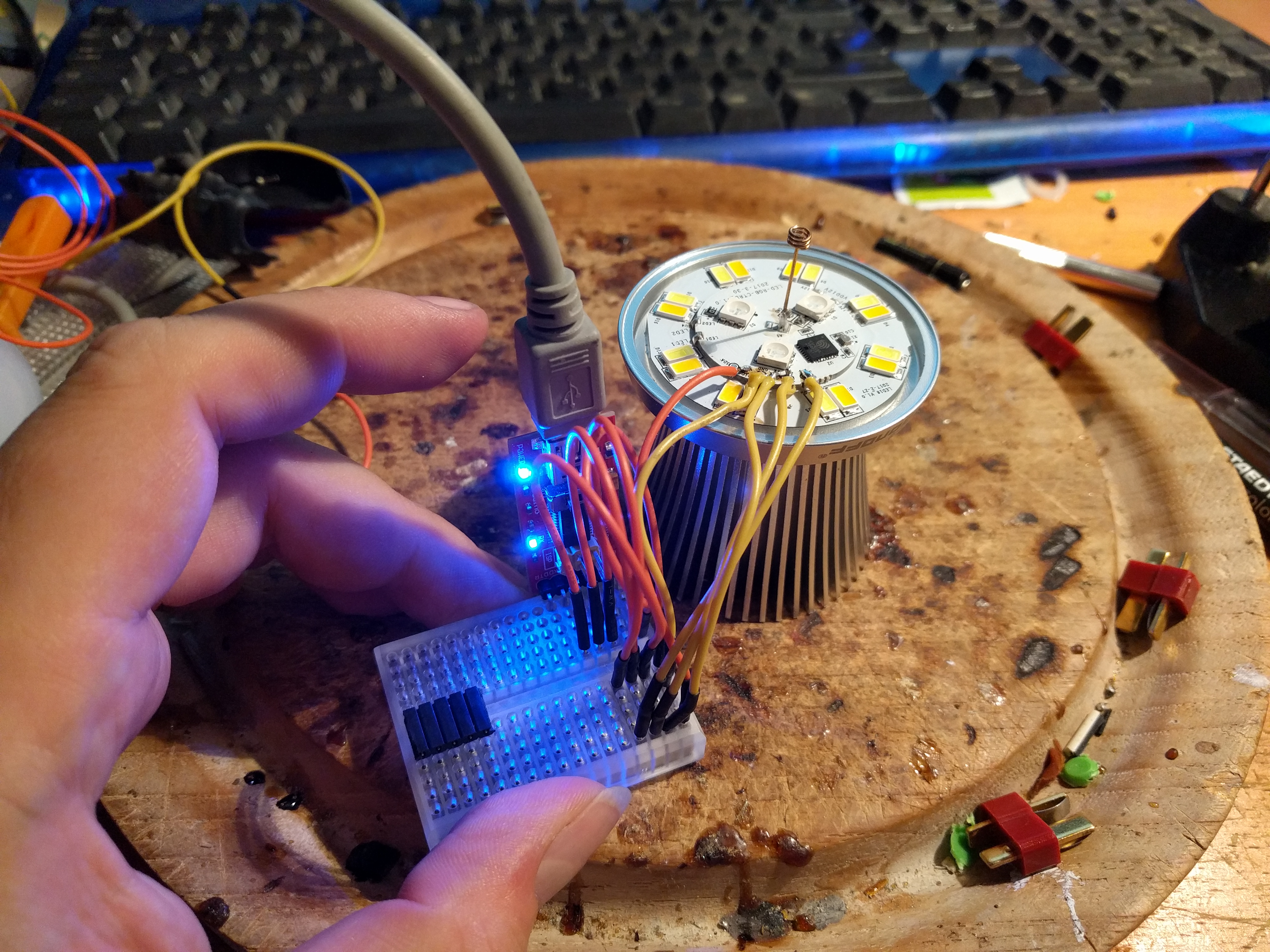
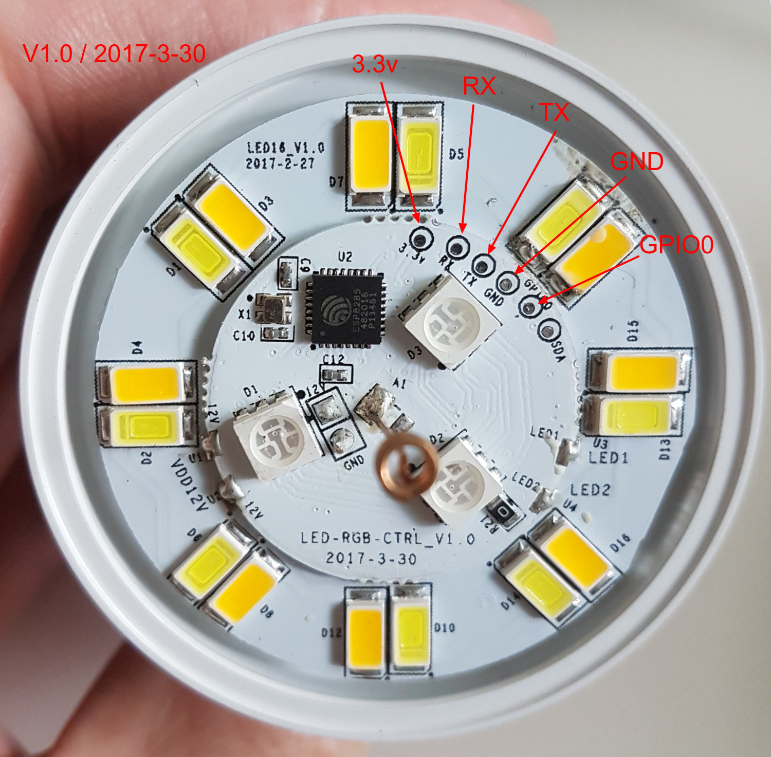
Now the final and most important question is where one will find the 4+1 pins. As can be seen in the image by @timtimsson they are available on the PCB as testpoints. In the image they are on the top half and clearly marked. You need to access these by either soldering wires to them or by using pogo pins as suggested above. To make connecting GPIO0 and GND easier for the less experienced tinkerers it's advisable to take the soldering path.
Good luck. If you follow these instructions please post pictures of the process to be added to the wiki for others.
ThomDietrich
on 15 Sep 2017
the connection to ground can be to the ground pin on your FTDI, or it can be a
connection between GPIO0 and ground somewhere on the device. It doesn't matter,
and some devices make one approach easier than the other.
The key is that to put an ESP chip into programming mode, you have to have
GPIO connected to ground before you apply power to the chip, if you have all the
pins in a header than you plug into, the angle that you hold the connector as
you plug it in will affect what order pins get connected, and if you connect
ground and power before GPIO0, the device will not be in programming mode.
davidelang
on 15 Sep 2017
Exactly. Even more details are given behind the wiki link I've posted.
@davidelang would you by any chance know which (if any) side of the LEDs is connected to GND? Also I can't see on the picture but the big test point in the middle right next to the antenna is probably GND as well?
ThomDietrich
on 15 Sep 2017
I've got an strange thing.
I connect first GPIO0, then the rest. It seems that the B1 is now in Programming Mode. The RX/TX Led on the FTDI goes on/off.
But during the Com Port detection from the Upload Phase, the ComPort from the DeviceManager is gone away.
I have tryed to programm an Sonoff SV Module, this works without any problems.
msth
on 15 Sep 2017
https://i.pinimg.com/736x/ef/ae/66/efae667cb9d38895bebb923f86a99d6a--ftdi-adapter-programming.jpg
My ftdi looks exactly like this, please explain to me the cables I should be using on this unit and then to the light. I'm honestly confused how the GND on the FTDI goes to the GND and GPIO0 on the B1
HellfireZA
on 15 Sep 2017
@ThomDietrich On the left, next to the Antenna, there's a 12V and GND (same as GND between TX and GPIO0).
I suppose mine picture shows that part clearer.
I tried to find an answer to your question whether the LED's are connected to this GND (or 12V), but unfortunately I couldn't detect this by using a resistance meter.
This evening I was able to solder wires to those little pads, connect to an FTDI programmer and flashing a new alternative firmware (Espurna in this case; but will try Tasmoto as well on this Sonoff-B1).
@HellfireZA Be sure that your FTDI uses 3.3V also on the RX/TX besides VCC, otherwise you could damage the esp8285.
You'll need to split the GND into 2 wires (1 for the actual GND and the other to connect temporarily (the first 3 seconds or so) to the GPIO0 pad. Maybe by using a breadboard, or by soldering some wires together.
I am using an seperate power module, like this:
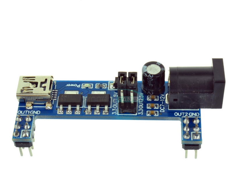
which has multiple GND and 3.3V pins which provides enough capacity power-wise.
 erkgh
on 15 Sep 2017
erkgh
on 15 Sep 2017
Great, thanks for posting the image @erkgh! Now it was super easy to write up the wiki article. Here we go.
ThomDietrich
on 16 Sep 2017
as I had hinted earlier, mine fried after I turned it of and on again 3 times in a short time.
never the less, I soldered some wires onto it and then I was able to flash it.
all worked well.
I also fitted a mini dean connector onto the 12V line and connected the round part to a 12V power supply.
worked like a charm.
just the RGB LEDs appeared to be not very well balanced. to get them to an even intensity, I had to:
`mosquitto_pub -t test/sonoff/cmnd/color -m 'ff37080000'
if anyone wants to use the pic for a howto, feel free to do so.
`
qorron
on 16 Sep 2017
oh, I missed the post from @ThomDietrich regarding the finished howto. I think this issue can be closed now ;-)
qorron
on 16 Sep 2017

Ok so I've got everything connected up as I'm sure it needs to be. I hold the GPIO0 wire onto the (black GND), flip the switch on the red wire for power, then release the GPIO0 wire from the black after 5 seconds. I'm still not able to get it into download mode so I must be doing something wrong.
HellfireZA
on 19 Sep 2017
Is your FTDI jumper'ed to 5V?
ThomDietrich
on 19 Sep 2017
No I've got it on 3.3v
HellfireZA
on 19 Sep 2017
Now the B1 is on the Tasmota's rails, is it à good product we should buy ? I have some milight bulbs I appreciate, some yeelights that I'm selling because of their horrible cold bad white color rendition.
 PeggyFree
on 20 Sep 2017
PeggyFree
on 20 Sep 2017
If you're into cold and warm white light the Sonoff B1 is just fine.
If you prefer (RGB) colors though I would go for the AiLight as the Sonoff B1 colors are just not bright enough.
arendst
on 20 Sep 2017
@davidelang how do you keep the pogo pins in place??
ageorgios
on 30 Oct 2017
@ageorgios you just have to find a way to position them safely on the pads for a few seconds. See
ThomDietrich
on 30 Oct 2017
I hold them in my hand during the flashing.
davidelang
on 30 Oct 2017
@ThomDietrich thank you I am wondering of such a way
@davidelang how do you keep 5 pins with your hand simultaneously!!??
I tried soldering and messed up :(
ageorgios
on 31 Oct 2017
Can someone indicate where is the actual driver code for this lamp?
I want to incorporate it in the HomeAccessoryKid base.
I already have the AI-Light working and expect little extra effort to make Sonoff B1 work.
TIA, HacK
 HomeACcessoryKid
on 1 Dec 2017
HomeACcessoryKid
on 1 Dec 2017
I've successfully flashed a Sonoff B1 to Tasmota 5.5.2b using SonOTA following the DNS spoofing procedure outlined here. I can't seem to manage to make the bulb successfully toggle on and off (both when the module setting was initially configured as a Sonoff Basic and when changed to Sonoff LED) or to change color via the Tasmota firmware web interface. Is there a particular module setting that I should be using?
 czyz
on 6 Dec 2017
czyz
on 6 Dec 2017
Nevermind! I compiled the latest development branch of sonoff-Tasmota (5.10.0a) which supports configuring the module as a Sonoff B1. I uploaded the minimal firmware to the bulb, then after that loaded I uploaded the full firmware. It's now working!
czyz
on 6 Dec 2017
i cant change color and what is the suggested configuration for home assistant to get full capability of lamp
 ahzazou
on 20 Dec 2017
ahzazou
on 20 Dec 2017
@ahzazou this might not cover all your questions but here you'll find the sum of special light commands: https://github.com/arendst/Sonoff-Tasmota/wiki/Commands#ws2812-ailight-sonoff-led-b1-bn-sz01-h801-and-magichome
ThomDietrich
on 20 Dec 2017
@ThomDietrich Thanks ,
i already checked the link very helpfull , but what i was asking is how can we use the color circle in HA , its not working
my HA config is below 👍
- platform: mqtt
name: "Guest RGB"
command_topic: "cmnd/sonoff103/POWER"
state_topic: "stat/sonoff103/POWER"
rgb_command_topic: "cmnd/sonoff103/COLOR"
rgb_command_template: "{{ '%02x%02x%02x' | format(blue, red, green)}}"
brightness_state_topic: "stat/sonoff103/RESULT"
brightness_value_template: "{{ value_json.brightness }}"
brightness_command_topic: "cmnd/sonoff103/DIMMER"
brightness_scale: 100
color_temp_command_topic: "cmnd/sonoff103/CT"
ahzazou
on 20 Dec 2017
@ahzazou that I can't tell you. Switch to openHAB 😜 No seriously, sounds like something you should ask in their forum.
ThomDietrich
on 20 Dec 2017
Hey! by any chance do you have a better datasheet of the My9231? cant figure out whats the resistor value for the mA of the OUT[A,B,C], any ideas?thanks!
 Xpcker
on 6 Mar 2018
Xpcker
on 6 Mar 2018
Hi,
I've just flashed Tasmota fw on an Arilux E27 led bulb. The upgrade worked fine, the web admin page works correctly but the bulb is behaving strange: regardless of the issued mqtt command/topic (color, power on, dimmer etc.) the bulb is always off.
In fact it is not really off: I plugged it in without the glass cap and the bulb is completely off unless I touch the aluminium body with my hand.
Once I do that, some of the colored leds are blinking at a very low brightness.
Here is a video showing exactly the issue.
I configured the bulb as Sonoff B1, but the behavior does not change even if I set other module types.
The mqtt commands are accepted by the bulb firmware:
00:28:47 MQT: tasmota/arilux1/stat/RESULT = {"POWER":"ON"}
00:28:47 MQT: tasmota/arilux1/stat/POWER = ON
00:28:50 MQT: tasmota/arilux1/stat/RESULT = {"POWER":"OFF","Dimmer":0,"Color":"000000","HSBColor":"0,0,0","Channel":[0,0,0]}
00:28:52 MQT: tasmota/arilux1/tele/STATE = {"Time":"2018-05-20T00:28:52","Uptime":"0T00:00:16","Vcc":3.174,"POWER":"OFF","Dimmer":0,"Color":"000000","HSBColor":"0,0,0","Channel":[0,0,0],"Scheme":0,"Fade":"OFF","Speed":1,"LedTable":"OFF","Wifi":{"AP":1,"SSId":"tlc3","RSSI":100,"APMac":"78:11:DC:53:10:15"}}
00:28:58 MQT: tasmota/arilux1/stat/RESULT = {"POWER":"ON","Dimmer":78,"Color":"C6C6C6","HSBColor":"0,0,78","Channel":[78,78,78]}
00:29:14 MQT: tasmota/arilux1/stat/RESULT = {"POWER":"ON","Dimmer":100,"Color":"FF1450","HSBColor":"345,92,100","Channel":[100,8,31]}
Do you have any idea what could be the problem here?
Is it possible that I shorted some pins while soldering the wires on the PCB? (even though I was very careful and there are no signs of over-soldering).
Thanks for your help!
 tlc76
on 19 May 2018
tlc76
on 19 May 2018
Images of two versions I have seen with their respective pinouts:

 robin13
on 15 Jan 2019
robin13
on 15 Jan 2019
Thanks for also adding those to the wiki! https://github.com/arendst/Sonoff-Tasmota/wiki/Sonoff-B1-and-B1-R2
ThomDietrich
on 15 Jan 2019
I got today my first B1 bulb and I've tried to open it - without success.
I used brute force to pop and/or to twist it.
Is this never model somehow protected against opening?
Any hint how to open it?
Thanks.

 pvydra
on 28 Jan 2019
pvydra
on 28 Jan 2019
@pvydra The milk-white plastic dome on the top needs to be popped off (not screwed!). It does just take brute force. I held the aluminium heatsink in my hands and forced the top off with two thumbs pushing up.
robin13
on 28 Jan 2019
@ThomDietrich Thanks ,
i already checked the link very helpfull , but what i was asking is how can we use the color circle in HA , its not workingmy HA config is below 👍
- platform: mqtt
name: "Guest RGB"
command_topic: "cmnd/sonoff103/POWER"
state_topic: "stat/sonoff103/POWER"
rgb_command_topic: "cmnd/sonoff103/COLOR"
rgb_command_template: "{{ '%02x%02x%02x' | format(blue, red, green)}}"
brightness_state_topic: "stat/sonoff103/RESULT"
brightness_value_template: "{{ value_json.brightness }}"
brightness_command_topic: "cmnd/sonoff103/DIMMER"
brightness_scale: 100
color_temp_command_topic: "cmnd/sonoff103/CT"
to use the circle color
`light:
- platform: mqtt
name: "B1"
command_topic: "cmnd/led_b1/power"
state_topic: "stat/led_b1/POWER"
rgb_state_topic: "stat/led_b1/color"
rgb_command_topic: "cmnd/led_b1/color"
brightness_state_topic: "stat/led_b1/dimmer"
brightness_command_topic: "cmnd/led_b1/dimmer"
color_temp_state_topic: "stat/led_b1/CT"
color_temp_command_topic: "cmnd/led_b1/CT"
payload_on: "ON"
payload_off: "OFF"
payload_available: "Online"
payload_not_available: "Offline"
optimistic: false
qos: 0`
 morgapa
on 15 Mar 2019
morgapa
on 15 Mar 2019
Related issues
 ximonline
·
3Comments
ximonline
·
3Comments
 smadds
·
3Comments
smadds
·
3Comments
 j4k3
·
3Comments
j4k3
·
3Comments
 abzman
·
3Comments
abzman
·
3Comments
 JoergZ2
·
3Comments
JoergZ2
·
3Comments
Most helpful comment
@pvydra The milk-white plastic dome on the top needs to be popped off (not screwed!). It does just take brute force. I held the aluminium heatsink in my hands and forced the top off with two thumbs pushing up.