H801 seems (according to the possibility to select it as type 20) already to be part of TASMOTA. However I could not find any directions/hints on its usage. What are the coresponding commands to deal with? The wiki has no idea on that one too.
 kruebsam
All 18 comments
Hi, this is very easy.
Read here: https://github.com/arendst/Sonoff-Tasmota/issues/387
If you have any questions, feel free to ask.
 Staars
on 5 Jun 2017
Staars
on 5 Jun 2017
sensors don't have any commands to deal with them, they just put data in the
tele/ reports once they are configured.
 davidelang
on 5 Jun 2017
davidelang
on 5 Jun 2017
Thanks for the Info. Is it OK if I update the WIKI accordingly by adding a section for H801 ?
Furthermnore I´d like to add a feature request: How about adding some more commands to the H801 implementation? Similar to the ones found on the 44key remote controls that normally come with the RGB-stripes. e.g.:
color red, green, blue
dimmer red, green, blue
fade on, off
leds on, off
kruebsam
on 5 Jun 2017
An H801 entry in the Wiki would be very welcome I am trying to control RGB lights through Hass and while I can send single commands manually have no real control system .
 osteospurnum
on 17 Sep 2017
osteospurnum
on 17 Sep 2017
I would like to use the H801 WiFi controller to control a white/warm white LED strip. So I flashed Tasmota to the device, made all settings correct, plugged the strip to the ports W1, W2 and VCC.
I managed to send commands like
cmnd/H801-01/PWM3
with values between 0 and 1023. The result is e.g.
stat/H801-01/RESULT = {"PWM":{"PWM1":3,"PWM2":1023,"PWM3":1023}}
But it does not have any effect on my white color at all.
Does anyone have an idea how I can control the light temperature mixing W1 and W2 an dimm my LEDs?
Thanks very much in advance!!!
 kisseler
on 15 Nov 2017
kisseler
on 15 Nov 2017
I think You should use PWM4 and PWM5.
Staars
on 15 Nov 2017
Thanks! And I did not get it right away, that I had to chose PWM4 & 5 for GPIO 4 & 14.

So issue solved. 😊
kisseler
on 15 Nov 2017
One more issue: I assigned the two white channels now to "R" and "G" (PWM1&2) in order to user GPIO4 and 14 as switches.
But I cannot achieve that switch1 (PGIO4) and switch2 (GPIO14) actually send out an MQTT message. I try to open/close the contact between the Ports and GND with no effect. I also tried to add another pull-up resistor.
It just won't react. I tried differect Values fpr switchMode (1) and switchTopic (1 or 2). Does anyone successfully use the GPIO4/14 for different purposes at all?
kisseler
on 17 Nov 2017
As far as I understand there is no GPIO-functionality on these ports on the H801.
What do you try to achieve?
Staars
on 17 Nov 2017
Well, I simply would like to use the "free" GPIOs to connect a normal wall switch (push button) an send signals ON/OFF via MQTT in order to control the light with an OpenHAB rule.
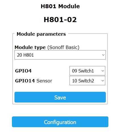
As far as I understand, this should be possible. Why else should one be able to select the connected device for GPIO4 (W) and GPIO14 Sensor (WW)?
kisseler
on 18 Nov 2017
Here is where I can select any device for GPIO4/14 on the H801
Does anyone have an idea how I can get this running?
kisseler
on 27 Nov 2017
The H801 has the source (input) of MOSFETs at GPIO4/14. You cannot connect a switch to the terminal blocks because they are connected to the outputs of the MOSFETs.
 elmicha
on 6 Dec 2017
elmicha
on 6 Dec 2017
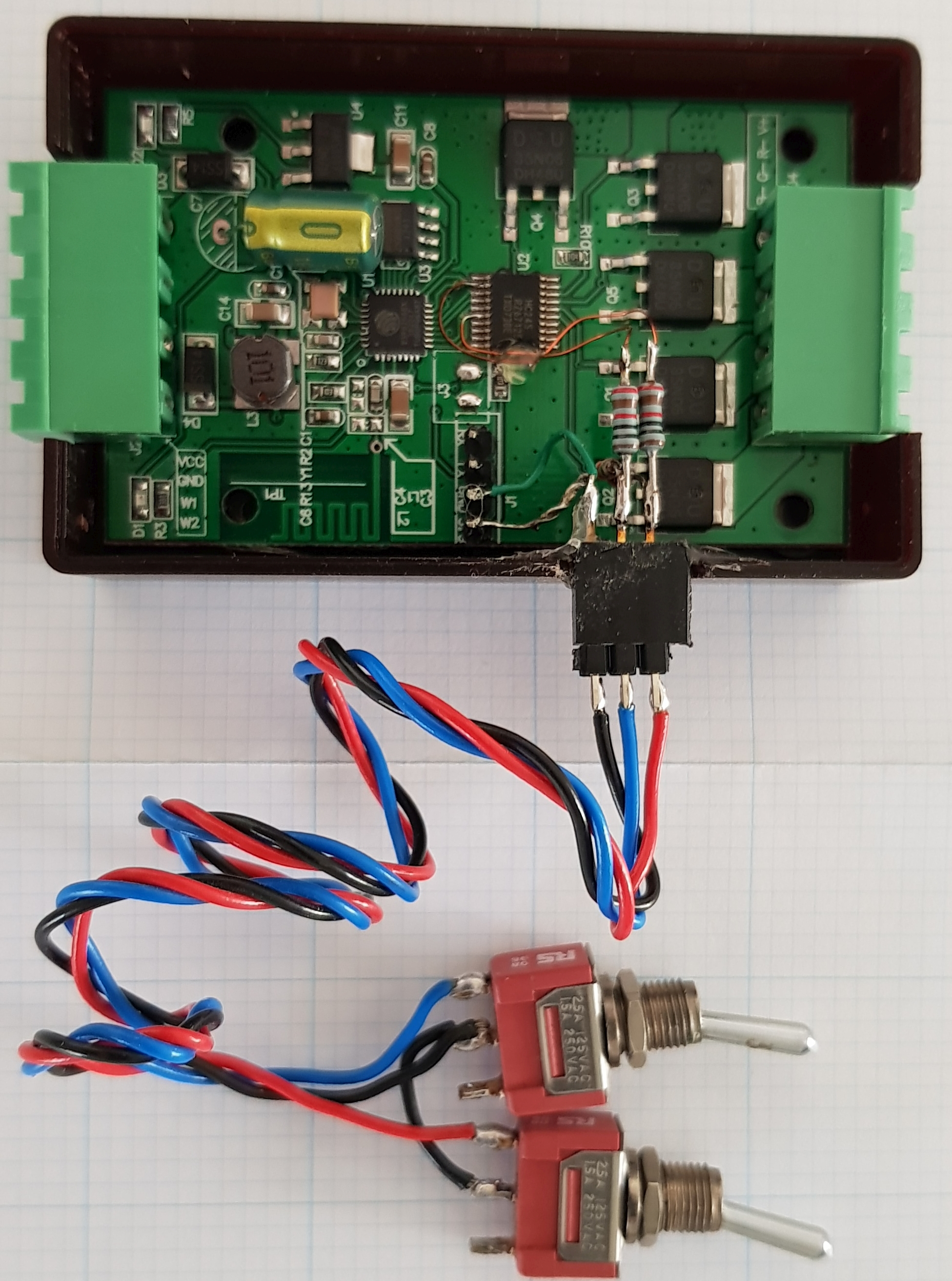
It is possible if you're keen... If you wish to use GPIO4 and GPIO14 as inputs for switches you need to connect directly to the ESP8266 pins. The 5 channels RGBWW connect from the ESP8266 chip to the HC245 chip. The HC245 chip then drives the individual mosfets. You could solder fine wires pins 2 and 6 of the HC245, which connect directly to the ESP8266 pins 9 and 16 (GPIO14 and GPIO4 respectively).
Cautions:
- Set GPIO14 and GPIO4 as inputs (switches) in Tasmota H801 configuration.
- These pins are 3.3V max input. Use appropriate input protection (10k series resistor and 4.7k pullup resistor).
- The WHITE1 and WHITE2 mosfets will also conduct according to your switch positions.
- You'll need to be keen, be able to solder... and have eyes like a hawk!
ESP8266 to HC245:
ESP8266 pin 9 GPIO14 HC245 pin 6 WHITE1
ESP8266 pin 10 GPIO12 HC245 pin 5 BLUE
ESP8266 pin 11 VDDPST
ESP8266 pin 12 GPIO13 HC245 pin 4 GREEN
ESP8266 pin 13 GPIO15 HC245 pin 3 RED
ESP8266 pin 14 GPIO2
ESP8266 pin 15 GPIO0
ESP8266 pin 16 GPIO4 HC245 pin 2 WHITE2
OK this mod looks like an interesing idea, so I thought I'd better try it: It appears to work, except when you toggle a switch, the H801's power state toggles. So 2 switches work like a 2 way light switch - you can toggle the power state from either switch. This is an interesting Tasmota firmware feature I assume, which requires firther investigation.
MQTT switch data with one switch on and other off:
tele/H801/SENSOR = {"Time":"2018-03-28T08:27:19","Switch1":"OFF","Switch2":"ON"}
Setting an input as "Counter1" works well too. Toggle the input with a switch or PIR and see the count:
tele/H801/SENSOR = {"Time":"2018-03-28T09:36:57","Switch1":"ON","Counter1":10}


 plasticbrain777
on 28 Mar 2018
plasticbrain777
on 28 Mar 2018
Wow, that's a great investigation and great solder work! I can barely hold the multimeter probes at these tiny pins.
As nobody mentioned it: we should be able to use the RX and TX pins as inputs, shouldn't we? We can configure it as a Generic module and assign RX and TX to different duties. I didn't try it, but it should work, I think.
elmicha
on 29 Mar 2018
@arendst
I need 3 GPIOs (I2C SCL, SDA and interrupt) for my RoomSensorAddon . Please consider moving wouterbaake's pull-request from development to master branch.
 renne
on 18 May 2018
renne
on 18 May 2018
You can also use the H801 module as an MQTT controlled IR remote and RGB LED strip controller. This is good for home cinema use for example. A spare white channel drives the IR LED - just an IR LED and resistor required. No modifications required. The H801 mosfets work at 38kHz, so no extra drive circuitry required. In this case "GPIO14 Sensor" is set to "08 IRsend". ... sorry about posting this info here - not sure where to put it. I just want people to be aware of this functionality before any useful tasmota firmware options are removed.
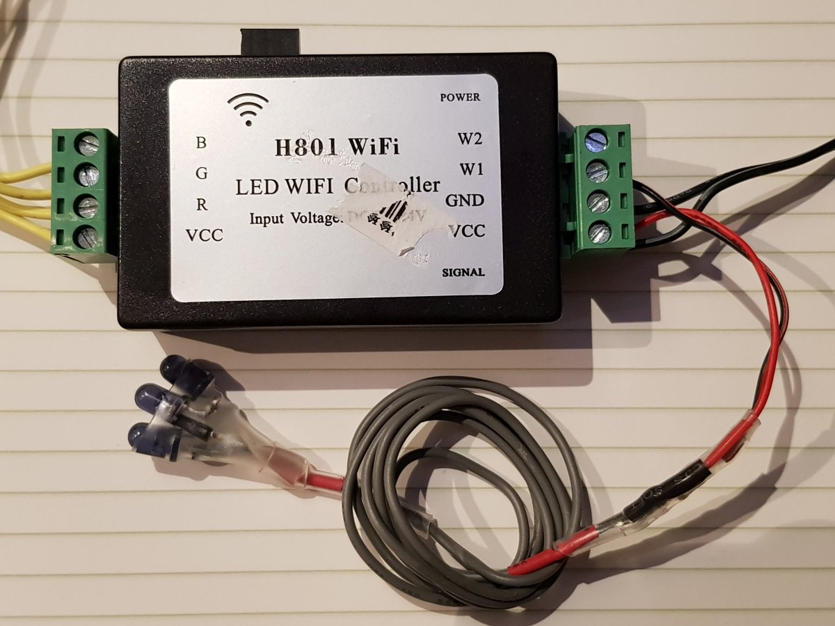
plasticbrain777
on 21 May 2018
@plasticbrain777
Great idea! I suggest the H801 Wiki-page.
renne
on 21 May 2018
Hi,
If your issue was solved, please close it. Thanks :+1:
 ascillato
on 13 Jun 2018
ascillato
on 13 Jun 2018
Related issues
 j4k3
·
3Comments
j4k3
·
3Comments
 Vujagig
·
3Comments
Vujagig
·
3Comments
 luisfpinto
·
3Comments
luisfpinto
·
3Comments
 TylerDurden23
·
3Comments
TylerDurden23
·
3Comments
 jensuffhaus
·
3Comments
jensuffhaus
·
3Comments
Most helpful comment
Wow, that's a great investigation and great solder work! I can barely hold the multimeter probes at these tiny pins.
As nobody mentioned it: we should be able to use the RX and TX pins as inputs, shouldn't we? We can configure it as a Generic module and assign RX and TX to different duties. I didn't try it, but it should work, I think.