Qmk_firmware: Firmware for my own 65% keyboard pcb design
Hi, I'm trying to make 65% keyboard from scratch. I finnished my own pcb design, I used ATMega32u4 microprocessor and I have usb type-C on my board, no LED, and I ordered it from jlcpcb factory, it will be delivered soon. I'm now wondering how to choose a right keyboard on QMK Configurator for a proper firmware, because pcb isn't bought it is my own design I'm not sure what to do for this problem. Thanks in advance for your answers and time.
 jancicS
All 8 comments
Typically two approaches.
- Go through the supported keyboards, find one closest to your design. Make a copy and start your modification.
- Generate a layout on KLE, import it to kbfirmware, edit and download the source files.
Mine as a reference: https://github.com/myst729/qmk_firmware/tree/master/keyboards/dg/xtrm
 myst729
on 6 Aug 2020
myst729
on 6 Aug 2020
if you designed your own PCB you will obviously not be able to use any existing keyboard in qmk but will have to create a new one with the matrix mapping that matches your own board.
like myst729 suggested, copying an existing keyboard and making your changes to that is probably the best option.
you should also read the documentation on how to create the layout macros for the matrix mapping and how to set all the necessary configuration parameters for the board.
 kb-elmo
on 7 Aug 2020
kb-elmo
on 7 Aug 2020
Ok, so I checked your code and also watched a mechmerlin stream on Twitch about this theme, I understand now what I'm supposed to do, but this part I quite don't understand well:
define MATRIX_ROWS 4 // this is ok I have, on my board 5 rows (from 0 to 4)
define MATRIX_COLS 12 // and 15 cols (from 0 to 14)
/* key matrix pins */
define MATRIX_ROW_PINS { D2, D3, F1, B7 } // <-- but this, is this like a specific pin mark for
define MATRIX_COL_PINS { F0, D5, F4, F5, F6, F7, C7, C6, B6, B5, B4, D4 } // ATMega32u4 or is there another explanation
/* This marks, { D2, D3, F1, B7 }, and { F0, D5, F4, F5, F6, F7, C7, C6, B6, B5, B4, D4 }, is it automaticaly assigned or is there any rule for this */
THIS IS YOUR GENERATED KEYMAP
#define KEYMAP(
K000, K001, K002, K003, K004, K005, K006, K007, K008, K009, K010, K011,
K100, K101, K102, K103, K104, K105, K106, K107, K108, K109, K111,
K200, K202, K203, K204, K205, K206, K207, K208, K209, K210, K211,
K300, K301, K303, K304, K305, K306, K307, K308, K309, K310, K311
) {
{ K000, K001, K002, K003, K004, K005, K006, K007, K008, K009, K010, K011 },
{ K100, K101, K102, K103, K104, K105, K106, K107, K108, K109, KC_NO, K111 },
{ K200, KC_NO, K202, K203, K204, K205, K206, K207, K208, K209, K210, K211 },
{ K300, K301, KC_NO, K303, K304, K305, K306, K307, K308, K309, K310, K311 }
}
Mine should be something close to it due to similar key numeration:
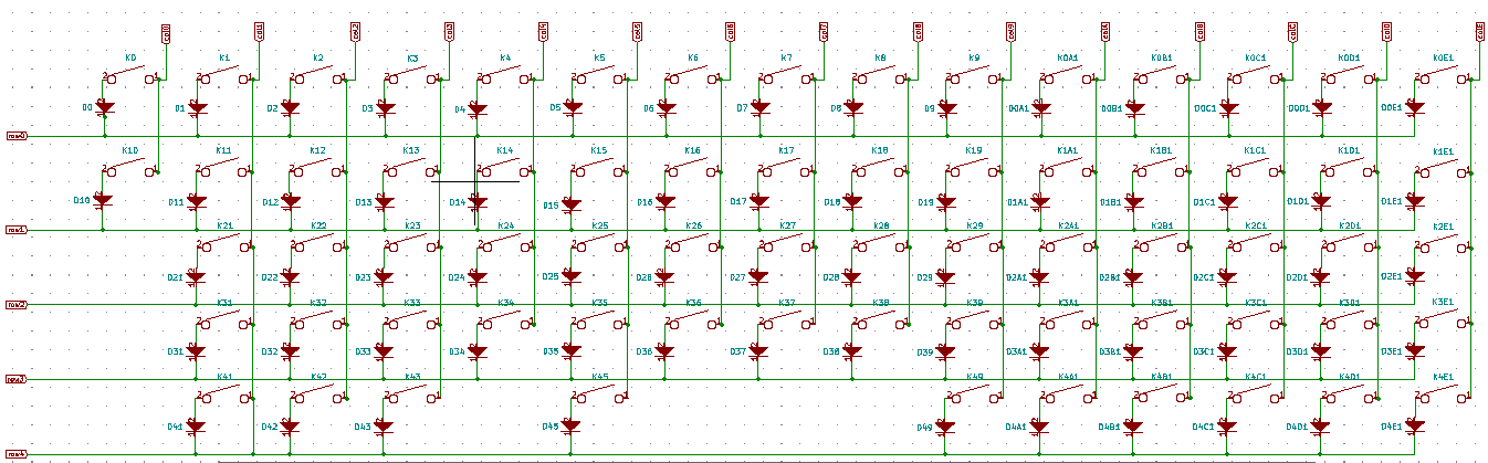
But will the pin mark be the same, I mean the only difference in code shuold be the matrix.
jancicS
on 9 Aug 2020
The pins for the rows and columns in QMK are the numbers of the pins on the controller where the rows and columns connect to.
You have to fill this out according to your PCB design. Otherwise QMK won't know how the matrix is wired up.
The keymap macro defines how the actual matrix is wired up electrically (in the second part of it) and how it looks physically on the PCB (the first part of the macro).
There is no way to generate this stuff automatically since QMK can't know how the stuff is wired up without your help.
You have to fill out all that information by hand.
kb-elmo
on 9 Aug 2020
Yeah, It is now more understandable for me, like on microcontroller there are pin marks on it, like PB6,PF6..., I saw some tip from mechmerlin on stream the day before and he found some site to generete it (https://kle2qmk.mrkeebs.com/) from keyboard layout editor raw data. But you have to put correct pin numbers in layout editor, but eventualy it was more precise doing it manually.
But in my case these PB6 is that like P for PIN and B6 for actual pin number?
And again, thanks for answers, you were so helpfull, this is my first time doing something like this.
jancicS
on 9 Aug 2020
Exactly.
PB6 would be called B6 in the QMK configuration.
kb-elmo
on 9 Aug 2020
Thank you so much! 🙇 😊
Hope I will make it work.
jancicS
on 9 Aug 2020
This issue has been automatically marked as stale because it has not had activity in the last 90 days. It will be closed in the next 30 days unless it is tagged properly or other activity occurs.
For maintainers: Please label with bug, in progress, on hold, discussion or to do to prevent the issue from being re-flagged.
![stale[bot] picture](https://avatars3.githubusercontent.com/in/1724?v=4&s=40) stale[bot]
on 7 Nov 2020
stale[bot]
on 7 Nov 2020
Related issues
 MarkuBu
·
3Comments
MarkuBu
·
3Comments
 Frefreak
·
4Comments
Frefreak
·
4Comments
 jetpacktuxedo
·
3Comments
jetpacktuxedo
·
3Comments
 henrebotha
·
4Comments
henrebotha
·
4Comments
 mrceephax
·
4Comments
mrceephax
·
4Comments
Most helpful comment
The pins for the rows and columns in QMK are the numbers of the pins on the controller where the rows and columns connect to.
You have to fill this out according to your PCB design. Otherwise QMK won't know how the matrix is wired up.
The keymap macro defines how the actual matrix is wired up electrically (in the second part of it) and how it looks physically on the PCB (the first part of the macro).
There is no way to generate this stuff automatically since QMK can't know how the stuff is wired up without your help.
You have to fill out all that information by hand.