Qiskit-terra: Gates are not left justified in mpl circuit drawer
Information
- Qiskit Terra version: master
- Python version:
- Operating system:
What is the current behavior?
There is always a space on the line between the qubit label and the first gate:
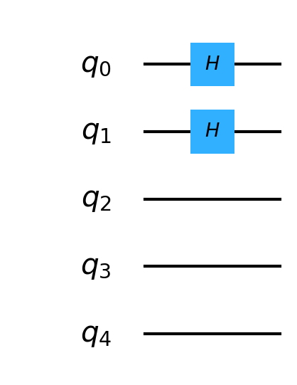
To reduce the width of the figure as much as possible, the gates should be drawn as far left as possible.
Steps to reproduce the problem
What is the expected behavior?
Suggested solutions
 nonhermitian
All 19 comments
@nonhermitian, is PR #3168 a fix for this issue?
 1ucian0
on 1 Jan 2020
1ucian0
on 1 Jan 2020
Hi,
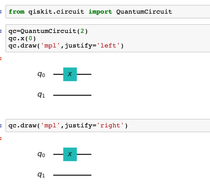
I was trying to look into this issue. The draw function has a parameter, justify. However if I use Justify='left' or justify='right' I do not see any change. Please help me to understand.
 souviksbhowmik
on 3 Jun 2020
souviksbhowmik
on 3 Jun 2020
I know this is an old issue, but I believe the reason for the extra room is for displaying bars for the folded (wrapped) rows. As in,
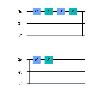
If the gates were moved to the left on the first row, either there wouldn't be enough room for the bars or the columns would not line up between the rows.
 enavarro51
on 26 Jun 2020
enavarro51
on 26 Jun 2020
@1ucian0 @nonhermitian Is this still open? If yes, can I have a go at this?
 abhobe
on 11 Sep 2020
abhobe
on 11 Sep 2020
I think @enavarro51 has some ideas about how to handle this.
Do you have bandwidth to work on this @enavarro51 or @abhobe can jump in?
1ucian0
on 11 Sep 2020
@1ucian0 The issue here has to do with what to do when the circuit folds as in my comment above. The solution I had suggested earlier (4 below) turned out to be more complicated than I thought. I see 4 options.
1 - Do nothing. It's only really noticeable on small circuits, but it is noticeable.
2 - Just move the first row gates to the left. The first row will be out of alignment with the folded rows below it, as will the index numbers if used.
3 - Remove the inner vertical bars at the beginning and end of the rows that fold, and leave the outer one. Don't know why there are two bars at each end except it looks like a musical clef. If we do this, it's easy to move all the gates left and just leave enough space between the single bar and a gate. This could reduce empty wire space at both ends.
4 - Only move the gates left if the circuit doesn't fold. Since folds are usually 20 or more indexes wide, the space at the left is much less noticeable for these large circuits. Problem with this is that as the code is currently structured, when you go to draw the first gate, you don't know if the circuit is going to fold or not, so a solution would require a significant restructuring of the code. (Which might be more efficient.)
My preference is for 3 and I'm happy to have @abhobe work on it, and I'd be available to answer questions.
enavarro51
on 11 Sep 2020
Thanks!
abhobe
on 11 Sep 2020
Option 3 sounds good!
1ucian0
on 11 Sep 2020
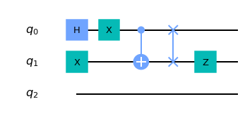
@nonhermitian Is this what is wanted?
abhobe
on 13 Sep 2020
Yes, that looks nice.
nonhermitian
on 13 Sep 2020
Ok, Here is what I did, changed line 687 from
self._line([self.x_offset + 0.2, y], [self._cond['xmax'], y],
                       zorder=PORDER_REGLINE)
to
self._line([self.x_offset + 1, y], [self._cond['xmax'], y],
                       zorder=PORDER_REGLINE)
This will solve the case only for one set of rows for the circuit. More sets will break the folds in the next lines.
I would also like to note that the gates are perfectly aligned when looking by the column. However, In the first row you will see there is an excess of white space since I removed the initial space wire.
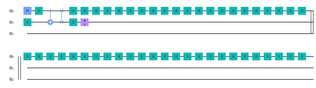
I like @enavarro51 's idea of removing one of those lines in the folds to increase circuit space. However, this did not solve the extra gate space in the beginning. So I thought of combining these ideas but the folds broke again.
@enavarro51 's Idea
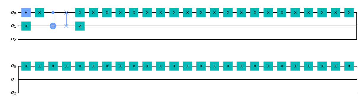
The combination
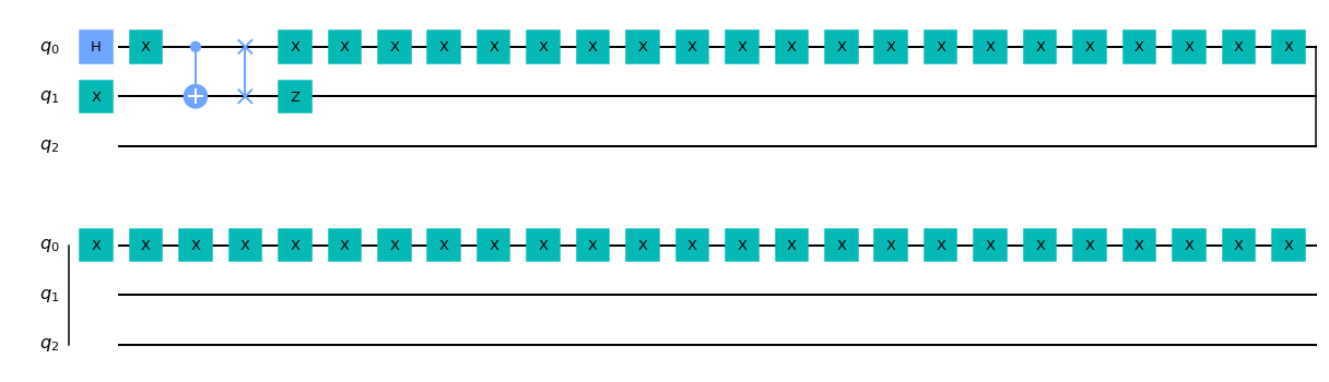
(Sorry for the random x gates)
abhobe
on 13 Sep 2020
@abhobe Are you on Slack? I think we can pick this discussion up over there. I have some ideas how to fix this.
enavarro51
on 13 Sep 2020
@enavarro51 Yes I am in slack. My slack handle also @abhobe
abhobe
on 13 Sep 2020
@enavarro51 and I had a discussion on slack on what the final result should be. So here is what we plan to make it look like.

- on the first set of qubits I removed the initial gate wire
We just need to find a way to seperate the first set of qubits from the next sets.
Note: The code for this has not been made yet. This was formatted on GIMP.
@nonhermitian @1ucian0
abhobe
on 14 Sep 2020
Looks good!
1ucian0
on 14 Sep 2020
@1ucian0 @nonhermitian I am pretty new to the qiskit source, could you point me to some functions which manage the length of the circuit wire length?
abhobe
on 14 Sep 2020
@enavarro51 can help. He knows the drawer very well.
1ucian0
on 14 Sep 2020
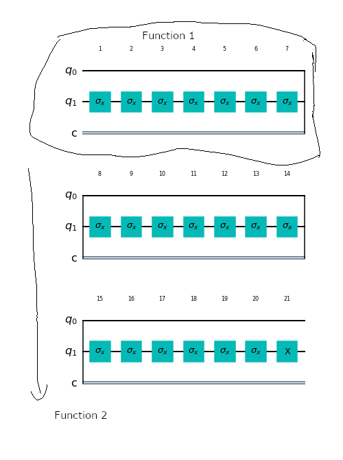
I think this is the best way to this. I am not sure about the proper terms but here is my idea.
We have a function draw() which takes in a param length (Again I do not completely understand the functions and what params they have but would like to know!). So the draw process would work like this:
- We will draw the first set of wires with
draw(len1) - Then we draw all the following rows with
draw(len2). (We won't need to do a lot of changes for this one since there is no shortening needed.
So maybe @enavarro51 could point out which function would be equivalent to draw()?
TL;DR
Is there a way we can separate the draw process for the first wire set and the rest?
abhobe
on 16 Sep 2020
There's really no need for the first row to be a different len. What you have above is just fine. You've significantly reduced the space already. We'll pick this up on Slack.
enavarro51
on 16 Sep 2020
Related issues
 ajavadia
·
5Comments
ajavadia
·
5Comments
 delapuente
·
5Comments
1ucian0
·
5Comments
delapuente
·
5Comments
1ucian0
·
5Comments
 cbjuan
·
3Comments
cbjuan
·
3Comments
 kdk
·
4Comments
kdk
·
4Comments