Pytorch3d: Potential misalignment in opt.cubify
🐛 Bugs / Unexpected behaviors
Cubify operation returns potentially misaligned vertices.
If I understand the expected behavior correctly, the mesh vertices will be put at the corner of each occupancy cell. For example, if I have a 4^3 voxels, the anchor vertices should be: [-1, 0.5, 0, 0.5, 1]. Now if this 4^3 voxels is occupied only in the inner cube like the following:
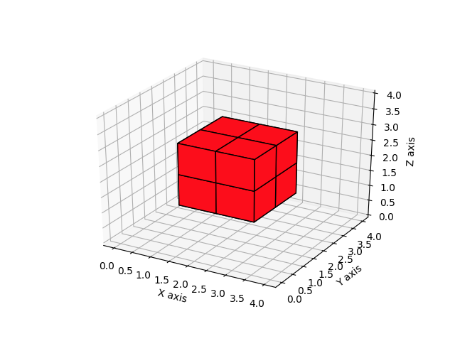
I should get the vertices like $\pm 0.5$
However, the output of cubify funciton is
v 1.00000000 1.00000000 -1.00000000
v 1.00000000 1.00000000 0.33333331
v 1.00000000 1.00000000 -0.33333337
v 1.00000000 0.33333337 -1.00000000
v 1.00000000 0.33333337 0.33333331
v 1.00000000 0.33333337 -0.33333337
v 1.00000000 -0.33333331 -1.00000000
v 1.00000000 -0.33333331 0.33333331
v 1.00000000 -0.33333331 -0.33333337
v 0.33333337 1.00000000 -1.00000000
v 0.33333337 1.00000000 0.33333331
v 0.33333337 1.00000000 -0.33333337
v 0.33333337 0.33333337 -1.00000000
v 0.33333337 0.33333337 0.33333331
v 0.33333337 -0.33333331 -1.00000000
v 0.33333337 -0.33333331 0.33333331
v 0.33333337 -0.33333331 -0.33333337
v -0.33333331 1.00000000 -1.00000000
v -0.33333331 1.00000000 0.33333331
v -0.33333331 1.00000000 -0.33333337
v -0.33333331 0.33333337 -1.00000000
v -0.33333331 0.33333337 0.33333331
v -0.33333331 0.33333337 -0.33333337
v -0.33333331 -0.33333331 -1.00000000
v -0.33333331 -0.33333331 0.33333331
v -0.33333331 -0.33333331 -0.33333337

f truncated....
which is clearly not centered correctly.
Proposed fix
I feel the occupancy grid here should be in the length of H instead of H-1.
diff --git a/pytorch3d/ops/cubify.py b/pytorch3d/ops/cubify.py
index e0fa345..5c0f06b 100644
--- a/pytorch3d/ops/cubify.py
+++ b/pytorch3d/ops/cubify.py
@@ -45,7 +45,7 @@ def ravel_index(idx, dims) -> torch.Tensor:


 @torch.no_grad()
-def cubify(voxels, thresh, device=None) -> Meshes:
+def cubify(voxels, thresh, device=None, fix_bug=False) -> Meshes:
     r"""
     Converts a voxel to a mesh by replacing each occupied voxel with a cube
     consisting of 12 faces and 8 vertices. Shared vertices are merged, and
@@ -169,12 +169,13 @@ def cubify(voxels, thresh, device=None) -> Meshes:
     y, x, z = torch.meshgrid(
         torch.arange(H + 1), torch.arange(W + 1), torch.arange(D + 1)
     )
+    dx = 0 if fix_bug else 1
     y = y.to(device=device, dtype=torch.float32)
-    y = y * 2.0 / (H - 1.0) - 1.0
+    y = y * 2.0 / (H - dx) - 1.0
     x = x.to(device=device, dtype=torch.float32)
-    x = x * 2.0 / (W - 1.0) - 1.0
+    x = x * 2.0 / (W - dx) - 1.0
     z = z.to(device=device, dtype=torch.float32)
-    z = z * 2.0 / (D - 1.0) - 1.0
+    z = z * 2.0 / (D - dx) - 1.0
     # ((H+1)(W+1)(D+1)) x 3
     grid_verts = torch.stack((x, y, z), dim=3).view(-1, 3)
With the fix, mesh vertices are as expected:
v 0.00000000 0.00000000 -0.50000000
v -0.00000000 0.00000000 0.50000000
v 0.00000000 -0.50000000 0.00000000
v 0.00000000 -0.50000000 -0.50000000
v -0.00000000 -0.50000000 0.50000000
v 0.00000000 0.50000000 0.00000000
v 0.00000000 0.50000000 -0.50000000
v -0.00000000 0.50000000 0.50000000
v -0.50000000 0.00000000 -0.00000000
v -0.50000000 0.00000000 -0.50000000
v -0.50000000 0.00000000 0.50000000
v -0.50000000 -0.50000000 -0.00000000
v -0.50000000 -0.50000000 -0.50000000
v -0.50000000 -0.50000000 0.50000000
v -0.50000000 0.50000000 -0.00000000
v -0.50000000 0.50000000 -0.50000000
v -0.50000000 0.50000000 0.50000000
v 0.50000000 0.00000000 0.00000000
v 0.50000000 0.00000000 -0.50000000
v 0.50000000 0.00000000 0.50000000
v 0.50000000 -0.50000000 0.00000000
v 0.50000000 -0.50000000 -0.50000000
v 0.50000000 -0.50000000 0.50000000
v 0.50000000 0.50000000 0.00000000
v 0.50000000 0.50000000 -0.50000000
v 0.50000000 0.50000000 0.50000000
 JudyYe
All 7 comments
Hi @JudyYe
The cubify op assumes that the top left corner of each voxel grid is aligned with its corresponding pixel coordinate. This is clearly debatable assumption. However, we went with this assumption because it was consistent with our vert_align operation which was then based on the default pixel alignment of the interpolate and grid_sample pytorch ops and it led to the right way of sampling from a 2D feature grid.
In contrast to our alignment that aligns the top left corners of the voxel grids with the integer coordinates of their corresponding pixels, you choose a different alignment. There is no wrong or right answer here. It all depends on what "pixel" is to your and your model you're designing! I am happy to change cubify so that it takes as input a flag that determines what alignment the user wants to use from a choice of alignments, we can start with ours and what you propose and if we need more alignments we can add more!
For completeness, in Detectron2, a different pixel alignment is assumed. There, pixels are considered to be centered at their 1x1 areas. If cubify follows that alignment, then cubified verts would start with negative verts and end with verts > 1. This alignment is somewhere in between what you propose and what we have in cubify. I am inclined to change the cubify alignment to that of D2, which is something I had in mind for a while but we can also support the case you are describing.
 gkioxari
on 4 May 2020
gkioxari
on 4 May 2020
Well, I made a diagram to showcase the alignment better!

Currently, cubify assumes the first alignment. Your proposition is the 2nd alignment. And if we follow D2, then we'd have the 3rd alignment. I think it's a good idea to support all these cases.
gkioxari
on 4 May 2020
Hi Georgia @gkioxari,
Thank you for the prompt reply. I totally agree that there are many alternatives on how to put coordinate and they may all be reasonable.
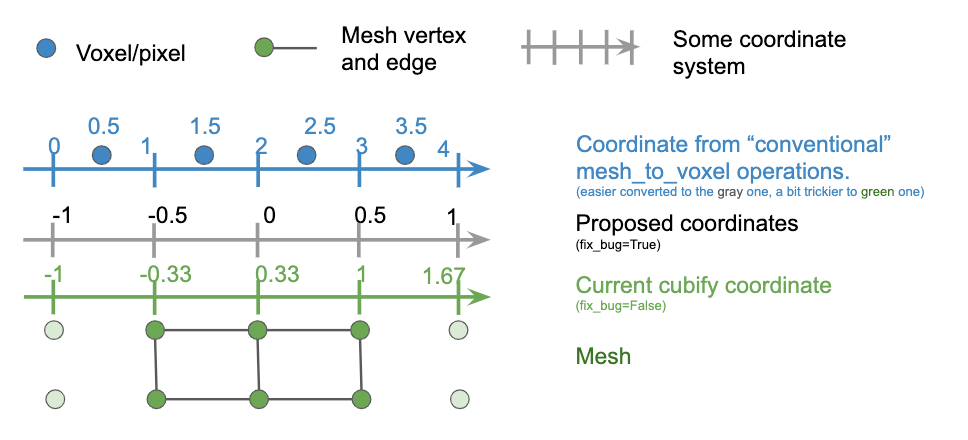
Thanks for your explanation. Now I understand that the current choice is preferable in the current version since it's consistent with the current verts_align. Same as your left figure, the following explains how to compute coordinate of vertices if it'd be helpful to others.
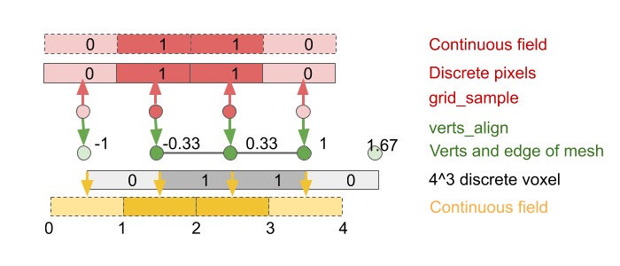
However, I'd like to add another motivation other than aligning pixels. What I proposed is more about consistency when the mesh is later re-voxelize back to a grid.
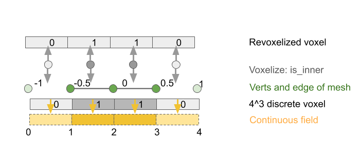
The main difference is that how we treat voxel, i.e. how it discretizes a continuous 3D field.
From this perspective, there is the _fourth_ alignment, slightly different from your middle figure.
Thanks!
JudyYe
on 5 May 2020
Hi @JudyYe
These figures are great! And they will certainly help others understand these subtleties with operations like cubify.
All the three alignments in my post above will be supported shortly via a commit. The middle alignment is exactly what you propose in your initial post by changing via
dx = 0 if fix_bug else 1
If you care to recover the initial voxel from the result of the cubified mesh, that's possible with all alignment schemes in my figure above, as long as your voxelization op is implemented as the inverse operation, i.e. by inverting the alignment. So the voxel can be recovered precisely, if the voxelization operation is the inverse operation taking the alignment into account, and all alignments proposed above are invertible. So you are good to go!
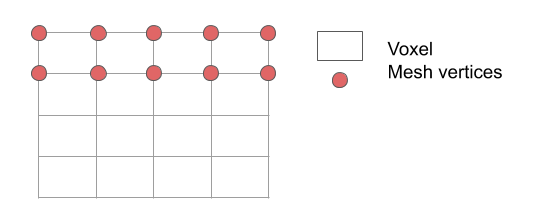
Now regarding your latest suggestion, I am a little confused. So let's stick to the 2D case for convenience. You assume you have a 4x4 image (in 3D it would be a voxel) where each pixel is described by (x, y) such that x = {0, 1, 2, 3}, y = {0, 1, 2, 3}. You now replace each pixel with a square. For pixel (0, 0), the square which will take its place will span (0, 0) - (1, 1) in pixel coordinates. For pixel (0, 3), the square will span (0, 3) - (1, 4). This becomes the 1st alignment in my figure above. Remember a pixel is just a (x,y) point (or in 3D, a voxel location is just a (x, y, z) point). We provide a span by replacing each point with a square (or in 3D with a cuboid). Maybe I am not understanding something though. I think I am confused of what the red dots and what the voxel means in your figure. Which one is the pixel (or in 3D, the voxel location)? I find it easier to represent pixels (or in 3D, voxel locations) with a dot, and represent the squares we replace them with with a square (or in 3D, cuboids). But in your diagram I find this a little confusing, so maybe I misunderstood your suggestion.
gkioxari
on 5 May 2020
Hi @gkioxari
Glad to hear those 3 alignment modes will be supported!
I agree that grid_sample itself has the 3 variants (top left, center, corner) as your figure illustrated.
The subtle difference is that there are two samples happening:
cubify: generate a mesh $(V, E)$ from a voxel $V_1$.verts_align/grid_sample: generate vertex feature from another voxel / pixel $V_2$.
If we consider both steps, what I initially clarified was just the number of vertices. I was saying in total there'd be 5 vertices generated and I'm not sure how to interpret the coordinate of 4 vertices (your figure). (I can see that it is also arguable that 5 vertices from 4 grids. But let's stick to that since the current cubify also assumes it.)
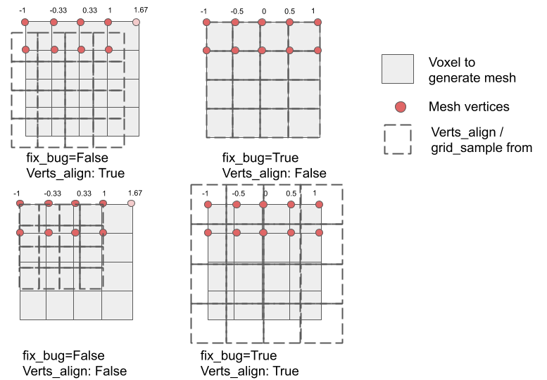
The top left is the current behavior (top left align). "Verts_align: True" is the shorthand for align_corners = True, where -1, 1 are mapped to the center of corner pixels. Note that there is the 5th vertex whose coordinate is greater than 1. Here I guess that the square in your figure corresponds to $V1$, my bold square "voxel to generate mesh" above.
The top right is my last figure in the previous post. It is similar to "corner align" in the sense -1, 1 is mapped to the corner of corner pixels. But there are 5 vertices totally. The verts_align can be independently true or false. (bottom right)
Now the bottom left is what I initially interpreted your "corner align", where -1, 1 mapped to the corner of corner pixels while there are 4 vertices in total. But here your square would correspond to $V2$, the dotted square in my figure.
In shorts, the misunderstanding seems due to 1) we were actually talking about two sample processes: cubify and verts_align. Your figure describes three choices in one grid_sample. 2) the number of vertices. The twist sneaks in if "square" refer to $V1$ or $V2$.
Based on the assumption that 5 vertices will be generated, the fix_bug only changes the vertex coordinate. It is independent of how the coordinates are interpreted later by verts_align (or voxlize_mesh). In either case, I agree with you that voxels can be recovered precisely if inverse operations are carefully implemented. However, fix_bug=True is desirable and friendly to voxlization since it's much easier to convert to "conventional" voelize_mesh operation.
JudyYe
on 5 May 2020
Hi @JudyYe!
I want to make sure I understand your post above. In all alignment modes (see my figure above), we add the same number of voxels and thus the same number of vertices. What differs between the modes is the range of the coordinates for the vertices. In all cases the input grid (left most in my figure above) ranges from [-1, 1] in each dimension. Each occupied pixel (x, y), where (x, y) \in [-1, 1] x [-1, 1], is replaced by a square. The vertex coordinates of that square with respect to (x, y) is what changes across the different modes. Other than that, nothing else changes. Your text above suggests that the number of added vertices changes so I wanted to clarify that this is not the case.
Commit https://github.com/facebookresearch/pytorch3d/commit/a61c9376d578525c218c2e0ba7eeedef3d418076 adds support for the different alignment modes. For your case, you merely need to specify align = "corner".
If that addresses everything, feel free to close the issue!
gkioxari
on 5 May 2020
Hi @JudyYe
I will close this issue. If you still have questions, feel free to re-open it.
gkioxari
on 7 May 2020
Related issues
 elcronos
·
3Comments
elcronos
·
3Comments
 farhanrw
·
3Comments
farhanrw
·
3Comments
 TheshowN
·
3Comments
TheshowN
·
3Comments
 unlugi
·
3Comments
unlugi
·
3Comments
 OmriKaduri
·
3Comments
OmriKaduri
·
3Comments
Most helpful comment
Well, I made a diagram to showcase the alignment better!
Currently, cubify assumes the first alignment. Your proposition is the 2nd alignment. And if we follow D2, then we'd have the 3rd alignment. I think it's a good idea to support all these cases.