Px4-autopilot: Elevator servo twitching in stabilized FW mode
To Reproduce
Steps to reproduce the behavior:
- UAV switched on
- Put on a leveled surface
- Press safety switch on
- Activate stabilized mode
- Move elevator to the maximum up or maximum down position by manual controls
- Wait few seconds for elevator servo twitch it will be repeated randomly
Expected behavior
I expect a stable output of servo command without any random glitch or twitching.
Log Files and Screenshots
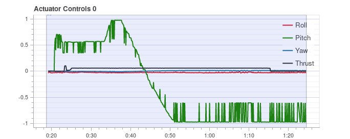
Following graph clearly shows elevator twitches
Additional context
The amplitude of glitch seems to be proportional and fixed to elevator deflection.
 kaklik
All 21 comments
As writing this bug report, I have noticed that elevator twitching has the same pattern as indicated airspeed. These two variables correlate perfectly.
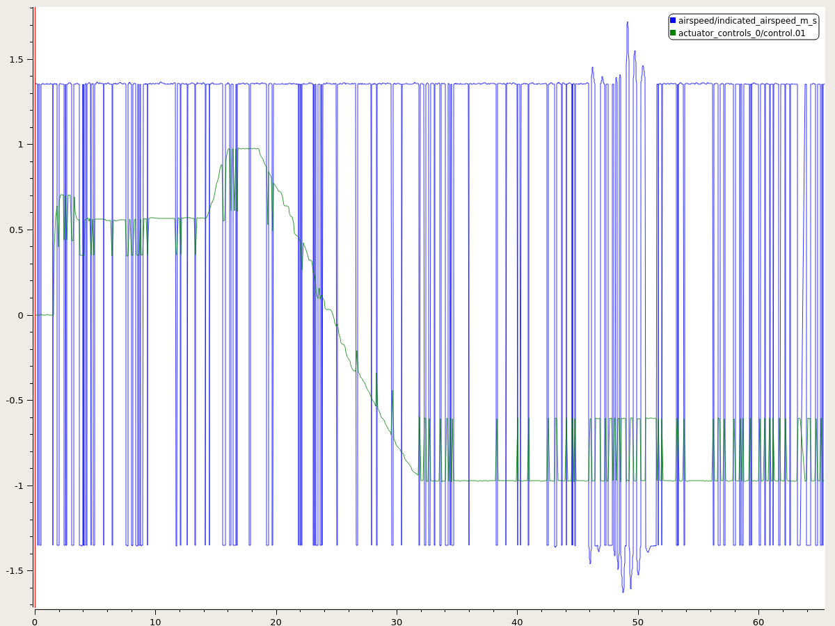
It seems this bug is related to airspeed elevator deflection scaling.
We use Drotek SDP33 based sensor.
kaklik
on 20 Apr 2019
@romanbapst @dagar let’s huddle and get airspeed scaling out of the way. We should be able to find a transfer function that makes sense and blends through a suitable range such that we don’t get actuator jitter at low air speeds or standstill.
 LorenzMeier
on 20 Apr 2019
LorenzMeier
on 20 Apr 2019
I saw the same thing on two different test planes. I'll have to see if I can locate the logs in our storage repo but this definitely happened several times on two different aircraft and both were equipped with SDP3x airspeed sensors. Pretty much exactly as described above.
 ryanjAA
on 21 Apr 2019
ryanjAA
on 21 Apr 2019
I have tested more scenarios yesterday. The results are:
- The bug affects also roll actuators, but the significant roll angle is needed to be noticeable in stabilized mode
- Twitching disappears in the following situations:
- The air is slightly blown along the pitot tube (airspeed is forcefully non zero)
- SDP33 ports are short-circuited by hose directly (airspeed is exactly zero)
- SDP33 sensor is disconnected from i²C.
These results confirm that the problem is caused by actuator scaling by fluctuating airspeed sensor output.
Is there some reason why the SDP33 driver is unable to output zero at low airspeeds?
kaklik
on 21 Apr 2019
The problem is the airspeed validity check in the FW attitude controller. If airspeed is near zero, but positive then airspeed min is used for the scaling. If airspeed drops below 0 it's considered invalid and airspeed trim is used for scaling.
 dagar
on 21 Apr 2019
dagar
on 21 Apr 2019
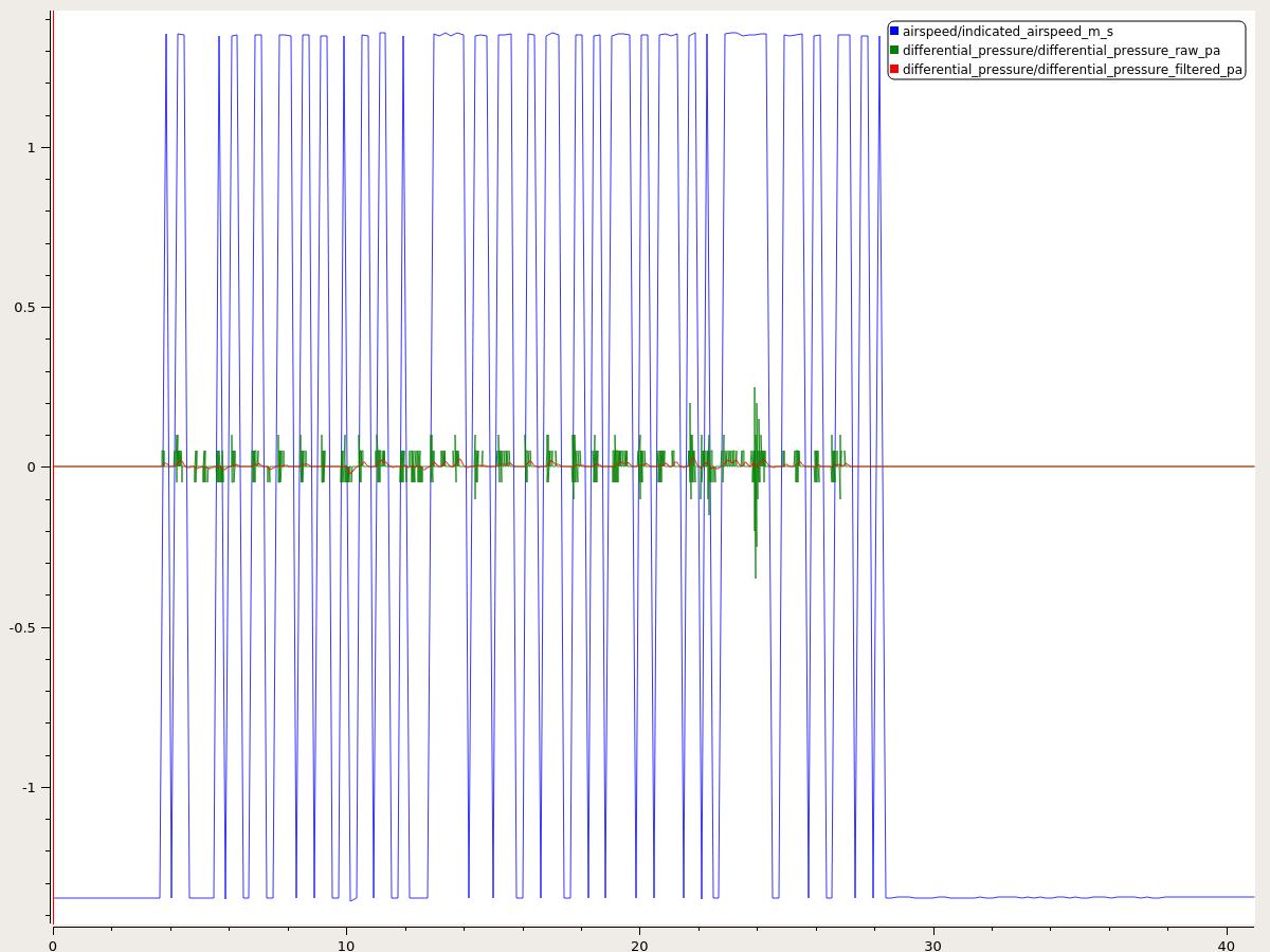
@kaklik the way your airspeed jumps between +- 1.3 m/s is odd. Can you also plot the differential pressure or share the full log? That will point us at the sensor driver or the calibration code.
dagar
on 21 Apr 2019
@dagar I searched in the full log from my initial post. But I could not find any variable which could be considered as raw differential pressure of pitot tube.
kaklik
on 21 Apr 2019
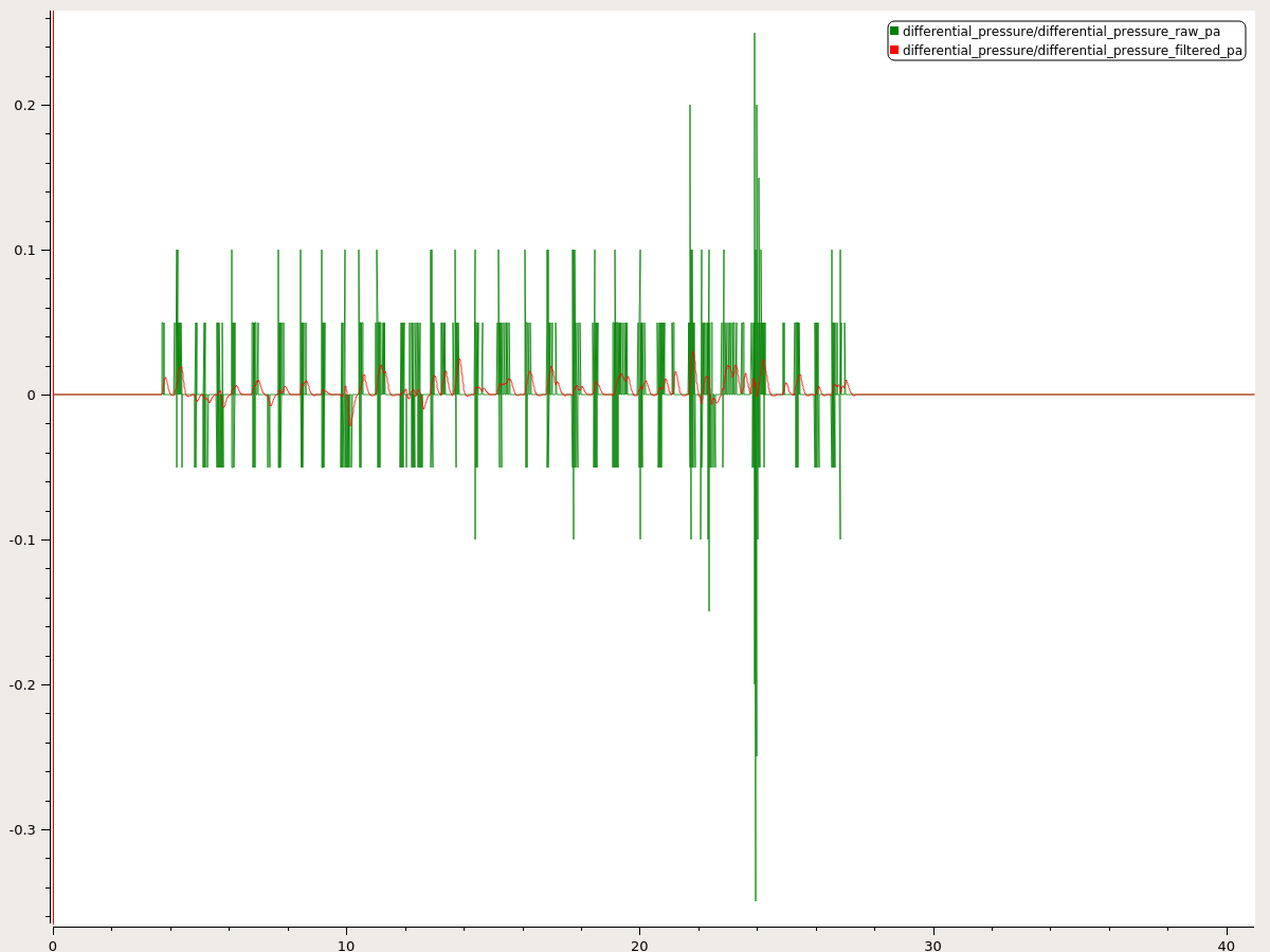
Ok, I have created a new file logger_topics.txt containing "differential_pressure" message.
The result is the new log file
kaklik
on 21 Apr 2019
The problem is the airspeed validity check in the FW attitude controller. If airspeed is near zero, but positive then airspeed min is used for the scaling. If airspeed drops below 0 it's considered invalid and airspeed trim is used for scaling.
I wonder if the vehicle is not flying, if the lowest speed scaling factor should just always be used? Although I could imagine certain takeoff scenarios in very high wind or launch rail or something where that might not be appropriate.
The [WIP] Airspeed Failsafe feature also has annoying interaction with this negative airspeed checker. Seems a better, more centralized architecture for all things airspeed related might be helpful, although I don't have any brilliant ideas how that might look (yet).
 Antiheavy
on 22 Apr 2019
Antiheavy
on 22 Apr 2019
In my opinion, the best solution for that trouble is the modification of the sensor driver.
There is no reason why the pitot tube airspeed sensor should output negative airspeed. Instead of this, the sensor should output the best possible estimate of measured airspeed (even if it should be zero) or an error message or message about sensor failure. The driver should not twitch between that randomly.
The negative airspeed should be reserved for a sensor with this capability e.g. ultrasound or ionization anemometers. This should not be used for checking the airspeed measurement validity on a higher level.
kaklik
on 22 Apr 2019
Sensor drivers should provide actual data, not try to be smart about the system. This has led in the past to people not realizing during airspeed calibration that their tubing was installed incorrectly.
LorenzMeier
on 22 Apr 2019
Let me list the design considerations here:
1) We should not have steps in the airspeed scaling. This issue is the result of a scaling change that @RomanBapst implemented such that airspeed could be used from very low speeds on during VTOL hover, and it has helped VTOLs after backtransition. Before that the vehicle needed to have airspeed_min readings (which is typically 8-15 m/s) and the noise level at that velocity is a lot lower due to the quadratic relationship between airspeed and differential pressure.
2) The quadratic relationship between airspeed and differential pressure is the core reason we see these artifacts: At very low speed the sensor noise can lead to 1-3 m/s of airspeed changes for the least significant bits
3) We have today two fundamentally different sensor types: One which is only effective at speeds > 6 m/s and one which registers 0.5 m/s.
LorenzMeier
on 22 Apr 2019
I believe the solution is to apply scaling which is fixed to a reasonable minimum parameter. This parameter will in practice be fairly constant, around 5 m/s and won't be necessary to tune. Deflections large than that are probably not reasonable. This will take away the jitter for any sensor configuration.
I'm not sure this addresses the scenario where the airspeed switches between positive and negative and the other logic switches from minimum scale factor to cruise/trim scale factor?
Antiheavy
on 22 Apr 2019
See the PR and it does.
LorenzMeier
on 22 Apr 2019
Sensor drivers should provide actual data, not try to be smart about the system. This has led in the past to people not realizing during airspeed calibration that their tubing was installed incorrectly.
I am glad multiple solutions emerged quickly here. But I am unable to imagine trouble where a driver with an internal check and incorrectly installed tubing will output an error message during calibration (where positive airspeeds are expected). It is the same behavior as now, but for now, the error is produced by the calibration process.
The solution based on the constant threshold value of minimum airspeed to apply scaling will bring implementation troubles in designs where low and relatively high airspeeds are used together. The example of that design is gyroplane with tailplane.
kaklik
on 22 Apr 2019
What you don't know is that the calibration is done in a higher-level component, so if we swap the sign of the airspeed sensor you can't detect that any more. That is a classic example of the design principle of separation of concerns: https://en.wikipedia.org/wiki/Separation_of_concerns
I still don't see what issue you predict. Feel free to propose a complete design or walk us through a case study where the updated design doesn't work. That would also ensure that you have the correct understanding of the new design (which can be a bit hard to follow given its all text and we haven't produced new documentation / diagrams yet).
LorenzMeier
on 22 Apr 2019
What you don't know is that the calibration is done in a higher-level component, so if we swap the sign of the airspeed sensor you can't detect that any more. That is a classic example of the design principle of separation of concerns: https://en.wikipedia.org/wiki/Separation_of_concerns
But I am not talking about swapping of the sign of measured airspeed. I am talking about the simple identification of failure of the sensor in sensor driver itself. The negative airspeed is, in fact, the type of sensor failure or incorrect installation. But it is only one from a very limited number of possible failures of sensor which could be identified on a higher level. The driver itself could identify much more types of failures even for future digital sensors.
Swapping sign of airspeed during a calibration process is not a good idea, because it is not failure proof during repairing or sensor mounting processes. The construction of the system could expect one direction of differential pressure, although the sensor itself is bidirectional.
I still don't see what issue you predict. Feel free to propose a complete design or walk us through a case study where the updated design doesn't work. That would also ensure that you have the correct understanding of the new design (which can be a bit hard to follow given its all text and we haven't produced new documentation / diagrams yet).
As I understand the proposed fix, there will be multiple airspeed constants. One of that will be a minimum measured airspeed from which the airspeed scaling will be applied to actuators.
The case study of trouble with that solution follows:
- I have construction capable to fly on very low airspeeds <= 2 m/s it is gyroplane with tailplane.
- The design has a large area of control surfaces, therefore the scaling of actuator deflection needs to be applied carefully.
- The lift of control surfaces has a quadratic relationship, therefore minimum value from which the scaling should be applied needs to be almost zero.
- But setting the value of minimum airspeed to scaling variable close to zero will result in almost the same situation as the current situation where we have flickering sensor between valid and invalid airspeed data.
kaklik
on 22 Apr 2019
Ok, I understand your concern now. Thanks for taking the time to detail it!
I forgot to mention two essential bits of information:
- Negative airspeed can occur at very low speeds due to turbulence around the pitot. So even in a correctly installed setup negative airspeed occurs in every flight (but only briefly).
- The MS4525 sensor can due to its ADC resolution only register airspeeds starting at ~6-8 m/s reliably. If you need to go below that you need a SDPXX type of sensor from Sensirion, which has a different measurement principle
- If you take the two points above together then you could operate with a configured sensing minimum of 0.5 m/s with a SDP33 sensor. That would allow you to do everything. The default of ~6 m/s for the config param will in the meantime ensure it works for all sensors for more traditional vehicles.
LorenzMeier
on 22 Apr 2019
@LorenzMeier Ok, I am probably capable to adapt solution you proposed.
It is obvious that negative airspeeds occur in an ideal configuration of the sensors. But in my point of view, it is essential that every particular sensor should be capable to say "I could not measure that relevantly, it should be zero airspeed but do not trust it."
In that situation, multiple sensors could be used to verify that value. It is because not every sensor will see negative pressure values due to turbulence.
I am unsure the configured minimum (0.5 m/s as your example) will fix that, because of the current implementation of SDP33 sensor driver is unable to output a zero airspeed (even in the case of measured pressure difference is zero). Instead of this the sensor continually flickers between the positive and negative value of 1.4 m/s.
kaklik
on 22 Apr 2019
Fixed in master.
LorenzMeier
on 24 Apr 2019
Related issues
 RomanBapst
·
5Comments
RomanBapst
·
5Comments
 robin-shaun
·
4Comments
robin-shaun
·
4Comments
 dk7xe
·
3Comments
dk7xe
·
3Comments
 wuxianshen
·
3Comments
wuxianshen
·
3Comments
 kainism
·
4Comments
kainism
·
4Comments
Most helpful comment
Fixed in master.