Prusaslicer: Make support separation distance configurable to negative numbers to keep ABS from warping
Version
Slic3r prusa Edition - 1.31.6-prusa3d
Operating system type + version
Mac OS X 10.11.6 El Capitan
Behavior
When changing the contact Z distance, and then examining the layers in the "Preview" tab, it is obvious that support distances between 0.2mm and 0mm are impossible to achieve.
In the following previews, I have a layer height of 0.1mm.
Here are my settings, with a Z distance of 0.01mm, and the distance between part and support layers is 0.33mm (part starts at 5.5mm above the plate).


However, lowering the Z distance to 0, results in the following support generation:


Note that the distance between support and part layers is now 0.1mm, or the actual layer height. Also note that support is generated inside the square, which I really don't want. I just want good support on the jutting out plate, not inside the square (which bridges fine).
There appears to be no way to get Z distances between 0 and 0.2mm.
This has been an ongoing bugbear of mine since I started using Slic3r (2 years ago).
STL/Config (.ZIP) where problem occurs
The file I'm using for testing is here:
Support test 8.stl.zip
 nebbian
All 41 comments
Regarding the gap, I believe Slic3r behaves correctly, though it is not evident at the first sight.
If you set the gap to zero, Slic3r expects you to print the supports with soluble material. Also in that case the bridges are printed with normal flow.
If you set the gap to non-zero, Slic3r expects you to print the support with non-soluble material, therefore the bridges are printed as threads of nozzle diameter. This adds the 0.2mm you have difficulty to explain as the bridged layer is (nozzle_dmr - layer_height) thicker downwards.
Regarding the support below the bridges, this is something I will need to address. I am currently finalizing new supports, so there will be a new set of bugs, but I am aware the supports below bridges are not fully suppressed in the new supports code either.
 bubnikv
on 27 Jan 2017
bubnikv
on 27 Jan 2017
I don't believe that it's working correctly. All I want is control over the gap between the support and the part. I've had to resort to building my own support in the model, and not using the automatic support that slic3r generates. This allows me to get the 0.1mm gap that I've been wanting, and the parts are coming out perfectly. Why can't the "0.2 - Detachable" option be "0.4 - Detachable"? This is actually what's happening. The gap isn't 0.2, it's 0.4.
Or to put it another way, how can I get a 0.1mm gap between support and the layer that's bridging the support? Currently there is no way that I've found.
nebbian
on 27 Jan 2017
Following screenshot shows clearly a gap of 0.1mm between the support contact layer and the bottom of your overhang. The layer height of the print is 0.2mm. You see that the bottom of the overhang is printed with a layer height of 0.4mm, that is the nozzle diameter. Indeed, it is printed with a bridging flow.


bubnikv
on 27 Jan 2017
There is indeed some logic in the way it works at the moment. But I'm with @nebbian , I don't like it. It doesn't work as well as adding a manual support with a defined smaller gap.
The point where I don't agree with the current logic is that the first layer above a support has to be printed with bridging flow (lines defined with a circular cross section of nozzle diameter). To me it makes much more sense (and it works on my models) to add for example 0.1mm space between support and first supported layer - but print this first layer with normal parameters. This way, there is less "squish" and therefore bonding strength between the support and the following layers and it's possible to remove it. And the supported surface looks way better than with briding flow, which looks always a little bit strange.
 Sebastianv650
on 27 Jan 2017
Sebastianv650
on 27 Jan 2017
@bubnikv Yes, I see what you're saying.
What I need is for the gap (in your screenshot it's 2.5 layers between the top of the bridge and the top of the support) to be smaller. I want to squish my bridge against the top of the support. This is what gives good adhesion between the support and the bridge above it.
There is no way to achieve this with the current way that slic3r is set up. If I could override the logic that assumes soluble support, then I could set a gap of -0.1mm and get what I want. However Slic3r tells me that this is invalid.
Oh well I'll go back to designing my support as part of the model, I guess.
nebbian
on 27 Jan 2017
This way, there is less "squish" and therefore bonding strength between the support and the following layers and it's possible to remove it. And the supported surface looks way better than with briding flow, which looks always a little bit strange.
Simplify3D uses the other tactics. Slic3r is the only kid on the block, who extrudes the bottom with the bridging flow.
It really depends. We tested both approaches, both have their pros and cons. The non bridging bottoms will have gaps between threads. Both could be configured to be easy to remove, this is just the way of setting the parameters.
I did not invent this, I just inherited it and now I am trying to justify the behavior. I see the benefits and downsides of it. It certainly works very well for horizontal overhangs and the bridging perimeters make slopes with very low angles printable, which is unique to Slic3r.
If you print the perimeters of the overhangs with a non-bridging perimeters, they will shrink back if not squished down to the support. With the bridging flow the threads will have a lower tendency to shrink, therefore they will be placed more precisely over the support. And the infill lines will have less gaps with the bridging flow than with the normal flow, unless you squish the normal flow lines against the support, but then you will not be able to remove the support easily.
bubnikv
on 27 Jan 2017
@nebbian
I see, your problem is, you get too little adhesion with the non-soluble supports. When you set the support gap to 0, Slic3r considers the support to be soluble, therefore it applies a completely different logic. If you need more adhesion, just set the gap to 0.001.
bubnikv
on 27 Jan 2017
@nebbian
Does a zero gap (configured by 0.001) not make the support bonded enough? Do you really need a negative gap to squish the bridging extrusions into the support? This will fuse the support into the print so badly, that you would have to cut it away.
bubnikv
on 27 Jan 2017
@Sebastianv650 I am always for a constructive discussion.
The point where I don't agree with the current logic is that the first layer above a support has to be printed with bridging flow (lines defined with a circular cross section of nozzle diameter). To me it makes much more sense (and it works on my models) to add for example 0.1mm space between support and first supported layer - but print this first layer with normal parameters. This way, there is less "squish" and therefore bonding strength between the support and the following layers and it's possible to remove it. And the supported surface looks way better than with briding flow, which looks always a little bit strange.
Everyone of us has a different requirement on the support. If you print something big and complex, your main concern will be an ease of removal of the support. If you build a solid support and squish the bottom of the object onto it, the bottoms will look good, but there will be no way to remove that from a complex model.
For a model provided by @nebbian, you may use a knife to cut away a fused support and the bottom will look great.
The threads at the bottom of the overhang will either be round, or squished against the support.
bubnikv
on 27 Jan 2017
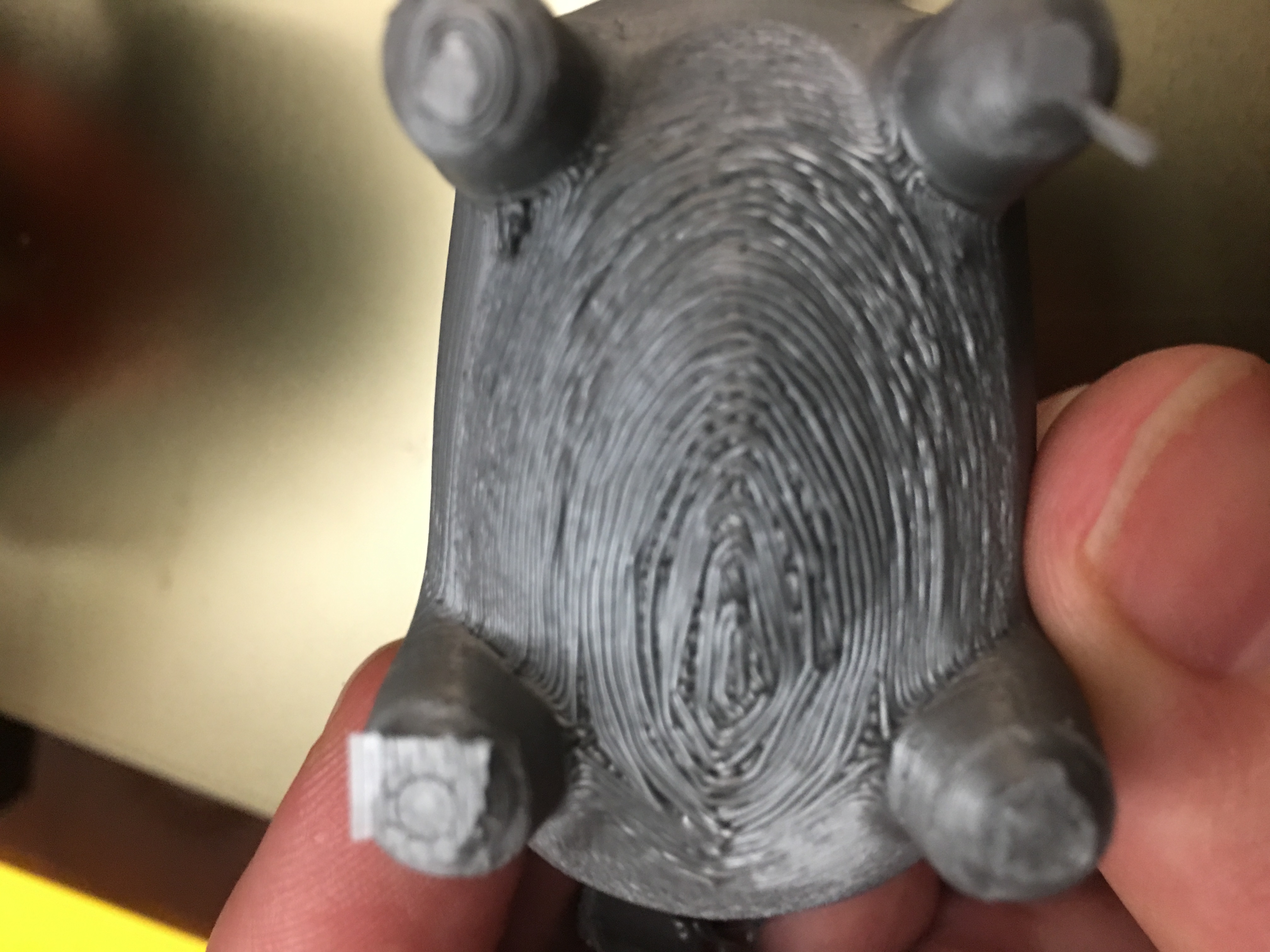
@bubnikv thanks for telling me how slic3r calculates the gaps, this has allowed me to figure out a workaround. Allow me to demonstrate the issue.
Here are three prints, all printed with a 0.3mm nozzle.
The first is using 'normal' slic3r support, 0.32mm nozzle diameter set in config, bridge flow ratio set to 0.95, 0.01mm support distance.
The second is with support turned off, but support done in the model itself.
The third is tricking slic3r into doing the support I want, by setting nozzle diameter to 0.2mm, and bridge flow ratio set to 2.432. Note for @Sebastianv650, you should be able to use this trick as well to get what you're after.
First:

Here are the images showing the lack of adhesion in the normal slic3r support setup:


Note that in all three cases, the support was easily removed by hand, with no knife needed. The bruising of the ABS is easily sorted out with a quick pass of a heat gun.
What I'm after is to be able to have the following layers (using 0.1mm layer height), bottom to top:
Layer 1: Top of support
Layer 2: Gap
Layer 3: Print the bridge.
At least now I can trick slic3r into doing the support I want, although having to use a bridge flow ratio of above 2 seems a bit... hacky.
The files to use are here:
nebbian
on 28 Jan 2017
@nebbian, realy nice idea! I will test it next time I need supports!
Sebastianv650
on 28 Jan 2017
@nebbian Brilliant.
 filipgoc
on 28 Jan 2017
filipgoc
on 28 Jan 2017
I see there is a hole to be patched in slic3r. Now, seriously. Please
provide stl files and the exported slic3r configs without the newly
discovered workaround applied, with the gap set to 0.001. We will print
them and we will evaluate, how well the supports work. I suppose you need
to apply this workaround for ABS only, right?
You are using the fact in your workaround, that slic3r does not respect the
bridge flow in the calculation of the support top surface. I shall fix
that. This will likely fix some of the issue of insufficient support
contact. If we find on your model examples that a negative gap is necessary
for a successful print with abs, I will enable some amount of a negative
gap.
By the way, are you using the support interface layers? I believe dense
interface layers will bond better to the overhangs.
On Jan 28, 2017 3:19 PM, "Filip Goc" notifications@github.com wrote:
@nebbian https://github.com/nebbian Brilliant.
—
You are receiving this because you were mentioned.
Reply to this email directly, view it on GitHub
https://github.com/prusa3d/Slic3r/issues/102#issuecomment-275850627, or mute
the thread
https://github.com/notifications/unsubscribe-auth/AFj5I2cYaEMNksgIAerJPMjRMHL1i3rMks5rW05rgaJpZM4Lqlm_
.
bubnikv
on 28 Jan 2017
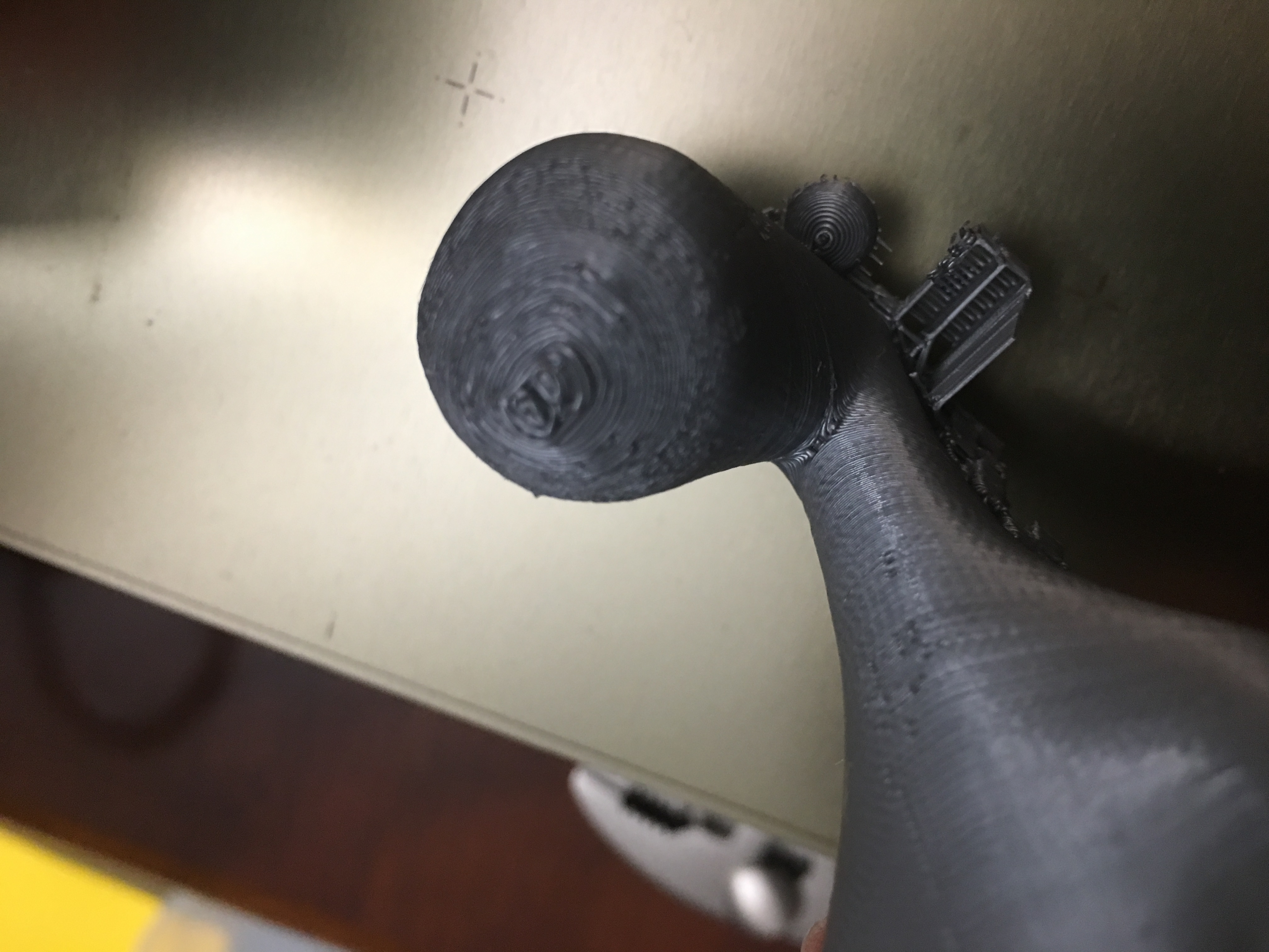
Thanks for taking this issue seriously @bubnikv.
As requested, I've attached the configuration file (set to the recommended settings you mentioned above), as well as a sample model that shows the issue.
Here are some pictures that show the problem. On the left is the print, using the recommended settings. On the right is a print, using the trick of lowering the nozzle size, and raising the bridge flow ratio to get the support I would like.
I hope it shows up in the photos, but all four cylinders are warped upwards using the recommended settings. All cylinders are adhered nicely using the nozzle size trick. In both cases, the support was easily removed by hand, no tools necessary.


I doubt that your cooling setup will be the same as mine, but I hope that it's similar enough to display the issue. I've had this same issue through several iterations of cooling setup, including:
- No cooling, with no enclosure
- No cooling, with enclosure
- Light cooling, with enclosure (as shown in the config file)
It would be fantastic if the support distance were able to be manually changed all the way up to what slic3r considers 'soluble', this would take care of any situation that I can conceive of.
nebbian
on 29 Jan 2017
By the way, @jonaskuehling proposes to slow down the bridges for good support adhesion & ABS.
https://github.com/alexrj/Slic3r/issues/2301
bubnikv
on 2 Feb 2017
See the discussion on raft
https://github.com/prusa3d/Slic3r/issues/118
It is a very similar issue to the one we are discussing. It will not be fixed in this release, but it is certainly something to be addressed.
bubnikv
on 17 Feb 2017
Glad to see this is being looked at -- this is probably the only shortcoming of Slic3r that presents itself regularly at this point.
Might I suggest that the use of bridging flow and the contact z distance should be completely independent settings? This would allow the user to configure Slic3r to behave in a way that works best for their usage and in my opinion make the configuration more intuitive and less 'black box' like.
 kelchm
on 28 Mar 2017
kelchm
on 28 Mar 2017
I just tested this work around for my first part, the front armour of "Sir Pigglesby", a PLA print. Realy, this is a complete new level of support quality! Never had such a result ever before with slic3r. The supports came of quite easy, nearly no knife needed for cleanup and the supported layers look nearly as good as a normal first layer printed on the bed. Even non flat (surfaces at an angle) supported faces worked this way, never got usable results with default slic3r behaviour.
I printed it with 0.2mm layer height with a 0.4mm nozzle. To get a real 0.1mm gap and a 0.2mm layer without this "bridge flow" 0.4mm layer height slic3r would generate on it's own, I set the nozzle diameter to 0.2 combined with a bridge flow of 3.2. Contact Z distance is then set to 0.1mm.
Maybe there are some cases where the default bahaviour is better, but in my eyes at least a switchable option to enable the logic described here would be awsome!
Sebastianv650
on 22 Apr 2017
This would be a great fix to have.
I've also gone the route of doing the above workaround of setting a false nozzle width (thanks @Sebastianv650 ) just so I can get my shapes to print. I print a lot of small figurines, and having what looks like a 0.3mm gap between the support and my object when I'm only printing 0.1mm layer thickness makes small features really hard to stick down.
 calculuschild
on 8 Jun 2017
calculuschild
on 8 Jun 2017
I want to give this a head-up. I'm using this work-around since @nebbian had this idea with a lot of success.
Here are two test pieces:
- A part with an evil 15° ramp, followed by a flat area completely hanging in the air.
- The lower portion of a sphere

I printed them twice, first time with my "special" settings with fake nozzle diameter and once with Prusa default values (Detect bridging perimeters, real nozzle diameter). Parameters in the support sections where the same in both prints:

The left ones of each pair is the Prusa / Slic3r default one, right one is with the settings from this thread. While mine look nearly as they were printed with soluable supports, the other.. Well, let the parts speak for itself:

Sebastianv650
on 5 Nov 2017
That looks convincing. I will try to get @jindrichbenes print some of those examples with the trick described.
bubnikv
on 6 Dec 2017
We have tried the workaround. It works as expected: While it improves the bottom surface, it makes it quite difficult to remove the supports. So if the supports are difficult to access, it will really be impossible to remove them.
We will make some changes to Slic3r to allow squishing of the bottom layer surface, but I don't think I will manage it in the upcoming release. You would have to wait for the next round. The good news is, we have new hires on Slic3r, so I hope to have time to finally implement interactive support editing.
bubnikv
on 13 Dec 2017
Anyone care to share the math/formula to make these adjustments if you aren't using a 0.3mm nozzle? I am using a 0.4mm nozzle and 0.15mm layer height and want to figure out what to set the nozzle and bridge flow rates to in my case. Thanks.
 chadwixk
on 23 Feb 2018
chadwixk
on 23 Feb 2018
I'm also using the default 0.4mm nozzle. The math is simple:
Nozzle diameter: 0.4mm
Normal used bridge flow factor: 0.8
Calculate the surface area A = (Nozzle diameter / 2)² * Pi * bridging factor = 0.10053096
Used layer height, which is entered as new nozzle diameter in Slic3r: 0.15mm
Gives a surface area A2 = (Layer height / 2)² * Pi = 0.01767146
So the new bridge flow factor needed is = A / A2 = 5.688889
Sebastianv650
on 23 Feb 2018
@bubnikv this nice workaround is no longer useable in latest Slic3r release as it checks for "valid" flow factors: "Configuration is not valid: Value out of range: bridge_flow_ratio."
Any chance to get some (maybe even hidden) option to disable this checks for crazy people like us?
Sebastianv650
on 31 May 2018
@nebbian , this workaround does wonders, thank you so much for sharing it (sidenote: obviously, extrusion widths needed to be manually specified).
@Sebastianv650 is it really non-trivial to disable this error in the current sources? Or do you have issues self-building Slic3r?
 paulfertser
on 13 Jun 2018
paulfertser
on 13 Jun 2018
@paulfertser it's maybe not that difficult to remove the warning, but my coding time is very limited at the moment and the "pain" wasn't high enough for me to search for it.
It was more a finding during another work, and I guess there are people out there using this work around which don't want to compile on their own.
Sebastianv650
on 13 Jun 2018
If someone is up for the task, we could gain a lot of flexibility in support settings by changing one line in xs/src/libslic3r/SupportMaterial.cpp. The line below (line 910 in current stable, I believe) calculates the Z height of the support material. If you remove the nozzle diameter (nozzle_dmr) from this calculation, the "Contact Z distance" setting should then define exactly the distance from the nozzle to the interface layer.
new_layer.print_z = layer.print_z - nozzle_dmr - m_object_config->support_material_contact_distance;
I'm an embedded developer, and have no experience building stuff on Windows. I'm going to see if I can do it, but if someone else could try it, that would be very wonderful.
 Chreutz
on 30 Jul 2018
Chreutz
on 30 Jul 2018
I am slowly looking into the support issues. The support generator code is pretty tricky due to the independent layering of the supports from the object layers. I have identified some errors (for example the bridging flow is not taken into account when calculating the support gap, the bridging perimeters are printed with bridging flow, but keeping the perimeter separation unchanged, leading to gaps), also I am trying to produce the support interface layers even for the perimeters not printed with the bridging flow, which again makes the code more complex. It will take some time to do it right.
bubnikv
on 30 Jul 2018
Nice to hear that someone cares for the support problems ;)
 Massa0815
on 31 Jul 2018
Massa0815
on 31 Jul 2018
FWIW, I was stuck using a Makerbot 2 and Makerware at my workplace for a few years. We just expected the supports to be difficult to remove (we didn't know it could be better), but I don't remember having problems as in these photos either, and this was with PLA with a layer thickness of 0.2.
It wouldn't be easy, but I could try to get an old coworker to print out a sample on the Makerbot to perhaps see how they approached the problem, maybe get some ideas...
 slate0
on 13 Aug 2018
slate0
on 13 Aug 2018
On Sun, Aug 12, 2018 at 10:10:19PM -0700, slate0 wrote:
I don't remember having problems as in these photos either, and this
was with PLA with a layer thickness of 0.2.
The key word here is _PLA_. It doesn't tend to curl upwards on
overhangs so it doesn't need supports to _pull_ it down. So there's no
use trying the samples in PLA.
FWIW the workaround as it is described in this ticket does wonders for
my usecase, the ABS overhangs look really clean and the supports are
(mostly) removable without a knife. That's without an enclosure.
My proposal would be to remove the limitation and to mention the
special treatment required by ABS in the help text.
--
Be free, use free (http://www.gnu.org/philosophy/free-sw.html) software!
mailto:[email protected]
paulfertser
on 13 Aug 2018
The key word here is _PLA_. It doesn't tend to curl upwards on
overhangs so it doesn't need supports to _pull_ it down. So there's no
use trying the samples in PLA.
Are we trying to fix the orange thingies in the pictures or not? I'm not going to assume what is causing the problem, but my PLA prints do exactly the same thing wherever something is built on a support.
I thought it would be obvious for anyone else talking about fixing this to have also tried PLA and to have realized that the problem is not exclusive to ABS.
slate0
on 13 Aug 2018
I am looking into this issue after a long time. I have identified the following issues:
1) Bridging flow incorrectly applied to the vertical separation gap, making the gap wider if the bridging flow correction is smaller than 1.
2) Supports printed at the bridging flow distance even in cases where the bridging flow is not used.
3) Infills printed with a bridging flow: There is an artificial gap added between the bridging threads to avoid one thread dragging by the other. The gap is given by the BRIDGE_EXTRA_SPACING constant to 0.05mm.
4) Bridging perimeters are printed with a bridging flow. If the bridging flow correction is smaller than one, the bridging perimeters are printed narrower than the normal perimeters, but at the original separation distance, making them disconnected.
I have a prototype of a fix for issues 1) and 2). I am looking into the other issues. I wonder whether "just" fixing these issues would satisfy all the complaints voiced in this thread.
bubnikv
on 4 Sep 2018
@bubnikv
I wonder whether "just" fixing these issues would satisfy all the complaints voiced in this thread.
I would be happy to test this out :-) Glad to read you are looking into this!
Sebastianv650
on 9 Sep 2018
I've been fighting this to varying degrees for a couple months now. I've been working exclusively in PLA.

and

I'm quite keen on making my bottom surfaces not have loose strings, holes, and off-shapes.
I'm going to try the above (if I can figure it out!) for a 0.6mm nozzle with 0.25mm layers.
Nozzle diameter: 0.6mm
Normal used bridge flow factor: 0.95 (not sure this is a smart number)
Calculate the surface area A = (Nozzle diameter / 2)² * Pi * bridging factor =.02686
Used layer height, which is entered as new nozzle diameter in Slic3r: 0.25mm
Gives a surface area A2 = (Layer height / 2)² * Pi =0.0491
So the new bridge flow factor needed is = A / A2 = 1.8275
I'm using 0.12mm as support Z distance, only support to 25 degrees, though I've found 15 to work as well.
I'm assuming none of these coding changes have made it into any compiled betas I can test?
Here's the little model I made, works pretty well for checking overhangs.
MicroMolPOLE.zip
 AbeFM
on 12 Sep 2018
AbeFM
on 12 Sep 2018
This is my current prototype.
I am looking into this issue after a long time. I have identified the
following issues:
- Bridging flow incorrectly applied to the vertical separation gap,
making the gap wider if the bridging flow correction is smaller than 1. - Supports printed at the bridging flow distance even in cases where
the bridging flow is not used. - Infills printed with a bridging flow: There is an artificial gap
added between the bridging threads to avoid one thread dragging by the
other. The gap is given by the BRIDGE_EXTRA_SPACING constant to 0.05mm. - Bridging perimeters are printed with a bridging flow. If the bridging
flow correction is smaller than one, the bridging perimeters are printed
narrower than the normal perimeters, but at the original separation
distance, making them disconnected.
I have a prototype of a fix for issues 1) and 2). I am looking into the
other issues. I wonder whether "just" fixing these issues would satisfy all
the complaints voiced in this thread.
Here is a prototype fixing 1) and 2), please try it. Also this prototype
should allow you to enter a negative separation offset.
There are now two new "modifier meshes": Support blockers and enforcers,
and there is a new check box to disable automatic support, and place
supports only where the enforcers are. The enforcers and blockers rely to
overhangs, from which the supports are derived.
I plan to add the support angle for the enforcers, currently the enforcers
place the supports as if the support angle was 90 degrees.
Slic3rPE-1.41.0+9-support-improvements-full-g6d...
https://drive.google.com/file/d/1IXaH6UX8nMK5E-VtK2nrWJKJW23onKaD/view?usp=drive_web
Slic3rPE-1.41.0+9-support-improvements-linux64-...
https://drive.google.com/file/d/1wkgAq8xvHoRA0hP4bggz3O3148XtEPeY/view?usp=drive_web
Slic3rPE-1.41.0+9-support-improvements-win64-fu...
https://drive.google.com/file/d/1-RBbpt9c21rGK8hzOvsWNVaHSYj9-R6C/view?usp=drive_web
On Wed, Sep 12, 2018 at 9:30 PM AbeFM notifications@github.com wrote:
I've been fighting this to varying degrees for a couple months now. I've
been working exclusively in PLA.[image: img_20180906_102108]
https://user-images.githubusercontent.com/42385/45447718-4b98a280-b685-11e8-8de5-f9f8b7d6e911.jpg
and
[image: img_20180911_160137]
https://user-images.githubusercontent.com/42385/45447729-54897400-b685-11e8-9092-fef4a4045063.jpgI'm quite keen on making my bottom surfaces not have loose strings, holes,
and off-shapes.I'm going to try the above (if I can figure it out!) for a 0.6mm nozzle
with 0.25mm layers.
Nozzle diameter: 0.6mm
Normal used bridge flow factor: 0.95 (not sure this is a smart number)
Calculate the surface area A = (Nozzle diameter / 2)² * Pi * bridging
factor =.02686Used layer height, which is entered as new nozzle diameter in Slic3r:
0.25mm
Gives a surface area A2 = (Layer height / 2)² * Pi =0.0491
So the new bridge flow factor needed is = A / A2 = 1.8275I'm using 0.12mm as support Z distance, only support to 25 degrees, though
I've found 15 to work as well.I'm assuming none of these coding changes have made it into any compiled
betas I can test?
Here's the little model I made, works pretty well for checking overhangs.
MicroMolPOLE.zip
https://github.com/prusa3d/Slic3r/files/2376558/MicroMolPOLE.zip—
You are receiving this because you were mentioned.
Reply to this email directly, view it on GitHub
https://github.com/prusa3d/Slic3r/issues/102#issuecomment-420769560, or mute
the thread
https://github.com/notifications/unsubscribe-auth/AFj5IzJfFSQTAdkHVb_cLQmnKiihDBk0ks5uaWDNgaJpZM4Lqlm_
.
bubnikv
on 13 Sep 2018
Hey @bubnikv . Thank you for the update :-). I look forward to trying it out.
Could you maybe be convinced to add an "advanced" option (potentially with a warning) to disable including the nozzle diameter in the support distance calculation? This would allow (advanced) users to dial in a distance themselves that fit their needs.
Chreutz
on 13 Sep 2018
Could you maybe be convinced to add an "advanced" option to disable
including the nozzle diameter in the support distance calculation?
I don' think it is needed or wished. I believe that may of the issues were
due to the bugs / limitations of the previous algorithm.
On Thu, Sep 13, 2018 at 9:20 AM Chreutz notifications@github.com wrote:
Hey @bubnikv https://github.com/bubnikv . Thank you for the update :-).
I look forward to trying it out. Could you maybe be convinced to add an
"advanced" option to disable including the nozzle diameter in the support
distance calculation? This would allow users to dial in a distance
themselves that fit their needs.—
You are receiving this because you were mentioned.
Reply to this email directly, view it on GitHub
https://github.com/prusa3d/Slic3r/issues/102#issuecomment-420908960, or mute
the thread
https://github.com/notifications/unsubscribe-auth/AFj5I_ZY06tFgJiV4qjUuE4-tbI_LfRrks5uagcjgaJpZM4Lqlm_
.
bubnikv
on 13 Sep 2018
I had a look into the new beta. While the gap is slightly smaller now (I'm using a bridging flow factor of 0.8), it's still not nearly as tight as we set it with the work around described in this issue.
So it's a step into the right direction, especially with the support modifiers, but the basic problem with a too wide gap for decent prints (in the meaning of this issue) is still open.
Sebastianv650
on 26 Sep 2018
can someone tell me what I am supposed to set the contact z distance support to without having to do engineering calculations? In cura i just hit print and it works... but I cant run cura headless, so I am trying to get used prusa slicer. I have done over 30 prints with prusa slicer and have yet to get it to work right with supports. I always just end up breaking the model in half trying to remove supports.
 diabl0w
on 26 Jul 2020
diabl0w
on 26 Jul 2020
Related issues
 nicksears
·
38Comments
nicksears
·
38Comments
 Itox001
·
35Comments
Itox001
·
35Comments
 GreatGrizzly
·
38Comments
GreatGrizzly
·
38Comments
 tobymurray
·
35Comments
tobymurray
·
35Comments
 carlvonkessler
·
42Comments
carlvonkessler
·
42Comments
Most helpful comment
@bubnikv thanks for telling me how slic3r calculates the gaps, this has allowed me to figure out a workaround. Allow me to demonstrate the issue.
Here are three prints, all printed with a 0.3mm nozzle.
The first is using 'normal' slic3r support, 0.32mm nozzle diameter set in config, bridge flow ratio set to 0.95, 0.01mm support distance.
The second is with support turned off, but support done in the model itself.
The third is tricking slic3r into doing the support I want, by setting nozzle diameter to 0.2mm, and bridge flow ratio set to 2.432. Note for @Sebastianv650, you should be able to use this trick as well to get what you're after.
First:

Here are the images showing the lack of adhesion in the normal slic3r support setup:


Note that in all three cases, the support was easily removed by hand, with no knife needed. The bruising of the ABS is easily sorted out with a quick pass of a heat gun.
What I'm after is to be able to have the following layers (using 0.1mm layer height), bottom to top:
Layer 1: Top of support
Layer 2: Gap
Layer 3: Print the bridge.
At least now I can trick slic3r into doing the support I want, although having to use a bridge flow ratio of above 2 seems a bit... hacky.
The files to use are here:
Long cylinder models.zip