Picongpu: Distortion of density profile at the end of the simulation
Hi
I have a question that haunted me all this time
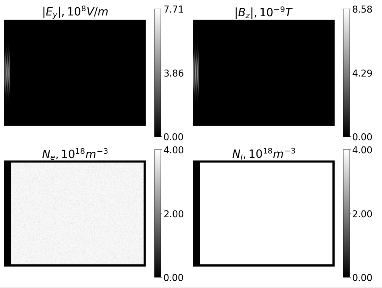
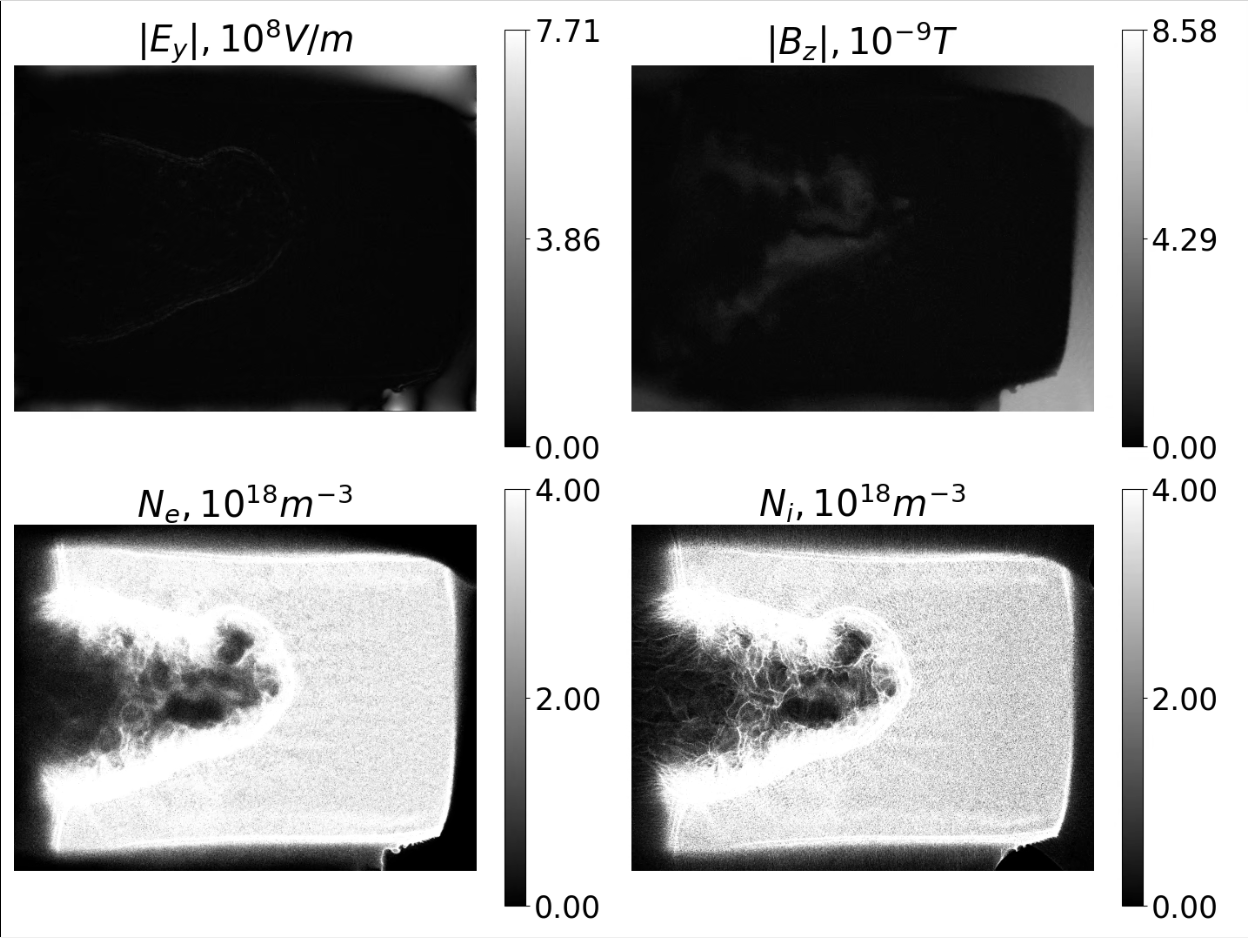
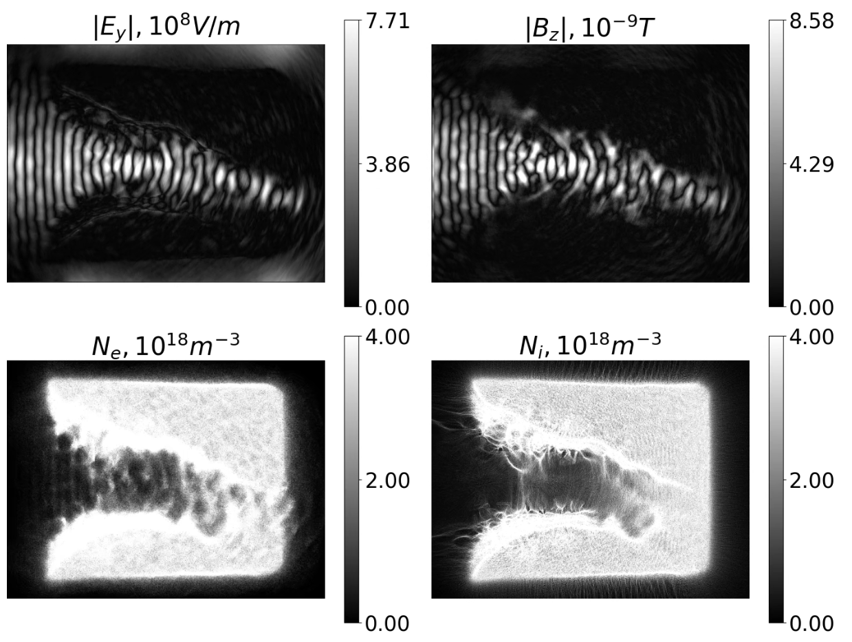
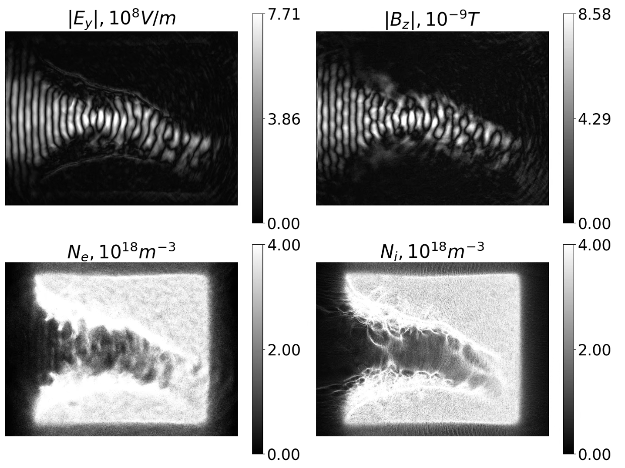
On this pictures You can see initial and final step of the simulation
Y axis - vertical(Unlike in picongpu)
Z axis - Looks inside the screen
Here's the code and also I can answer any questions or do what needed
On pictures You can see that during simulation density profile shrinks on edges
Also strange fields appears which cause this effect
There was no problem with that until I decided to run long simulations, in which the problem only got worse. Density profile was shrinking more and more
I was running simulation with smaller dt, dx, but nothing has changed
So I decided that it can be linked with deleted particles, that flew out of the simulation area
Here is the e_macroParticlesCount, i_macroParticlesCount, output
I'm asking for Your help in understanding what this effect is connected with and how its influence can be reduced .
 Theodotus1243
All 11 comments
From the files you provided I gather that you did not try to run the simulation with periodic boundary conditions? (i.e., --periodic 1 0 1)
Loss of particles on the boundary would suggest an influence from the boundary condition onto the density and given that your siulation is 2D the influence is severe.
 Anton-Le
on 1 Nov 2020
Anton-Le
on 1 Nov 2020
I think @Anton-Le is right. You ran with absorbing boundary conditions (TBG_periodic in your .cfg file) and your speciesInitialization.param has initial temperature. So it looks like particles near the boundaries flew off the absorbin boundaries because of their initial random momentums.
We currently do not have reflective or outflowing boundaries for particles, the choice is only between periodic and absorbing.
 sbastrakov
on 2 Nov 2020
sbastrakov
on 2 Nov 2020
Yes this is the common "feature" if you have non-zero-temperature particles that leave the simulation box on the boundaries.
 PrometheusPi
on 2 Nov 2020
PrometheusPi
on 2 Nov 2020
Thanks @Anton-Le, @sbastrakov, @PrometheusPi
I have not fully understand everything yet. But I already have some observations. Please help me to deal with them.
--periodic 1 0 1 removed strange fields from Ey. Thanks
1) Also I ran --periodic 0 0 1, but nothing has been changed(as I see)
As mentioned in documentation, see below...
So to get wire particles do I need to set periodic Z, or what is the difference in periodic Z ={0,1}?
It seemed to me that the condition simDIM=DIM2 itself implies periodicity in Z
How to correctly initialize TBG_gridSize and TBG_periodic in simDIM=DIM2, if we are talking about Z dimention?
A 2D3V simulation in a cartesian PIC simulation such as ours only changes the degrees of freedom in motion for
(macro) particles and all (field) information in z travels instantaneous, making the 2D3V simulation behave like
the interaction of infinite “wire particles” in fields with perfect symmetry in Z.
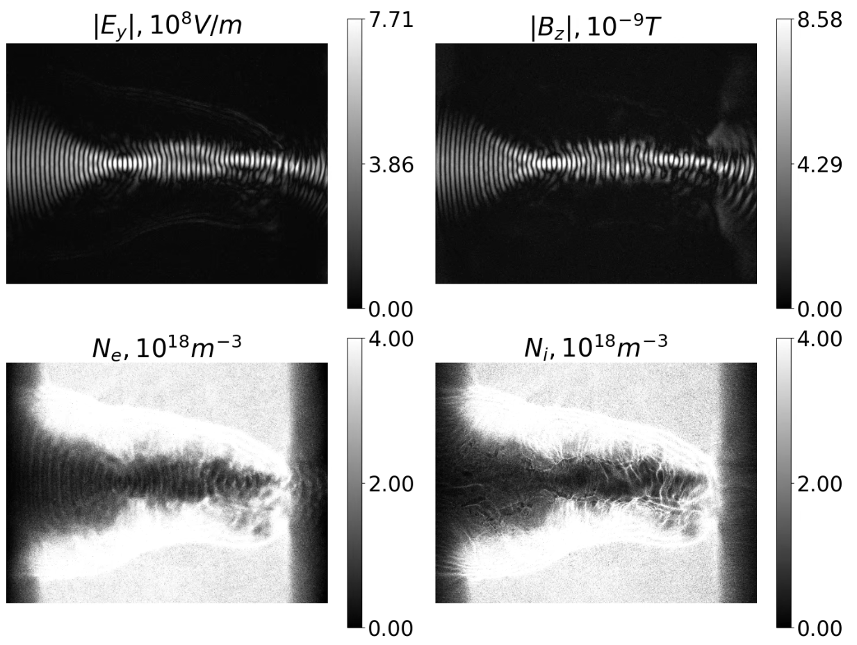
2) After using --periodic 1 0 1 amount of deleted particles and the difference between the number of electrons and ions was decreased
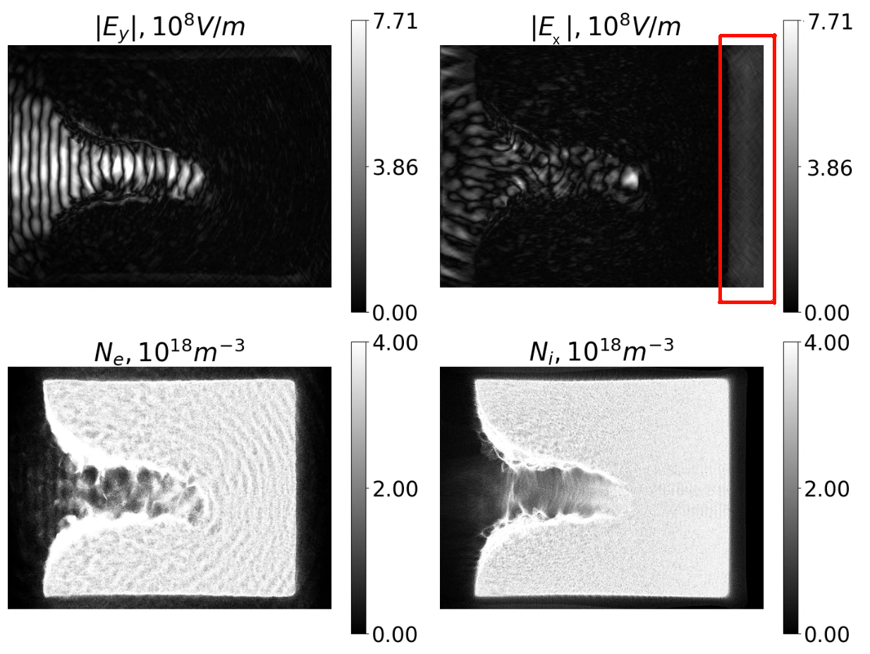
And strange Ey fields disappeared. But if we look on Ex, it is still present.
It looks like that the fields disappeared due to the switching-on periodicity, but not due to a decrease of removed particles from simulation. Isn't it?
So there is no way to remove strange Ex fields, because we can't set --periodic 1 1 1 and use laser at the same time?
Don't misunderstand. Your solution is good, I am just collecting knowledge to understand when these effects can harm reliability of results
Theodotus1243
on 3 Nov 2020
For a 2D simulation, the third number in grid size and periodic is just not used. You can either specify it as vectors of size 2, or can leave off as vectors of size 3, just the last component will never be read. You are right that a 2D simulation is exactly the same as a 2D XY-slice (with z=const) of a 3D simulation where nothing changes along z (so not just periodic along z, but constant along it).
sbastrakov
on 3 Nov 2020
Regarding the laser, you are right. Currently, PIConGPU only applies laser if boundaries along Y are not periodic.
sbastrakov
on 3 Nov 2020
Sorry to split my answer in several parts.
Finally, regarding Ex at the right side of your pictures. I am not exactly sure, but can't it result from the fields generated at the right edge of your density?
sbastrakov
on 3 Nov 2020
Thanks @sbastrakov
About Your question
You are right. Plasma emitted fields are present in the red circled area. But if You will look closer(You can do it by clicking on the image to open it on full size) there are two fields, as I see.
High frequency field emitted by plasma. And some static electric field
To support this statement I will show, how similar static electric field but in Ey disappeared after switching-on --periodic 1 0 1
But, the weak electric fields from the plasma was remained
I don't mean to mislead You. But these are the results I got
And I will continue to study this question. And perhaps the situation will manifest itself on the other side
But also if You have any thoughts, I am very interested to hear them. I'll be glad if I'm wrong and these are plasma emitted fields
If the phenomenon turns out to be physical, then of course the question is removed and given to me for study
Left --periodic 0 0 0. Right --periodic 1 0 1
Theodotus1243
on 3 Nov 2020
Thanks for further investigation @Theodotus1243 . edit: nevermind, it was my setup that changed it, everything was right in your post. I assume due to github formatting it turned out the top image file with 4 plots is for non-periodic (called "left" in your post), and the bottom one with 4 other plots is for periodic in X, absorbing in Y (called "right" in your post).
@PrometheusPi @Anton-Le if you have time, could you have a look?
sbastrakov
on 4 Nov 2020
Hello,
I am careful with periodic conditions in PIConGPU since I noticed that particles lost at one edge enter at the other edge. It seems that periodic refers to continuation.

Maybe this is the correct behaviour but at the time I was looking into how to impose some symmetries such that the computational resources go for example in half of the target but the Physics refers to the whole target.
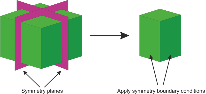
I can see however that in PIC codes such symmetry planes are not possible because they need a certain condition to be imposed there, as for example only tangential electric field, as it is the case with resonating microwave cavities, while this is not correct in laser-plasma interactions.
So with PIC we need to handle the computational power and time required for targets larger in their transverse dimension, when mesh needs to be fine.
Yet another suggestion for PIConGPU developers would be to allow nonuniform meshing. This would allow users to focus the resources at the core of the interaction while having a large enough structure for the absorber and mesh this one less tightly.
 cbontoiu
on 10 Nov 2020
cbontoiu
on 10 Nov 2020
@cbontoiu yes, periodic boundaries imply symmetry with regards to the global simulation volume. I am also not aware of how to easier do symmetries on a smaller scale, however in case you know it or have some relevant papers please share!
Regarding nonuniform meshing, it is of course a very powerful feature for certain simulations. Unfortunately, it also seems to be very demanding development-wise, and e.g. currently we do not have it in development. However, while the grid is always uniform, there is another "dimension" to management of computational resources = how the computational area is subdivided between MPI ranks (and with GPUs each MPI rank corresponds to one GPU). For this, we support rectilinear non-uniform domain decomposition, using --gridDist in a .cfg file. It is very briefly described here. So this should help in case your macroparticles are distributed non-uniformly but following a certain structure (e.g. a target is only in a certain area).
sbastrakov
on 11 Nov 2020
Related issues
PrometheusPi
·
3Comments
sbastrakov
·
3Comments
cbontoiu
·
3Comments
 hightower8083
·
4Comments
hightower8083
·
4Comments
 ax3l
·
4Comments
ax3l
·
4Comments
Most helpful comment
@cbontoiu yes, periodic boundaries imply symmetry with regards to the global simulation volume. I am also not aware of how to easier do symmetries on a smaller scale, however in case you know it or have some relevant papers please share!
Regarding nonuniform meshing, it is of course a very powerful feature for certain simulations. Unfortunately, it also seems to be very demanding development-wise, and e.g. currently we do not have it in development. However, while the grid is always uniform, there is another "dimension" to management of computational resources = how the computational area is subdivided between MPI ranks (and with GPUs each MPI rank corresponds to one GPU). For this, we support rectilinear non-uniform domain decomposition, using
--gridDistin a.cfgfile. It is very briefly described here. So this should help in case your macroparticles are distributed non-uniformly but following a certain structure (e.g. a target is only in a certain area).