Odm: Generating a footprint and average % overlap
At some point during reconstruction, is it possible to produce an estimate of overlap or generate something like this:

I think it would help with benchmarking and being able to discriminate between bad runs and bad photosets.
 dakotabenjamin
All 41 comments
This will be a valuable feature added to ODM!
 rionlerm
on 2 Oct 2015
rionlerm
on 2 Oct 2015
Thatd be a great feature.
 Bavar2142
on 29 Jun 2016
Bavar2142
on 29 Jun 2016
I wrote about a different way to view sparse point cloud data using OpenSfM's web view feature- maybe we can incorporate the camera positions from that JSON data, then calculate the image boundaries from there?
dakotabenjamin
on 29 Jun 2016
Thanks for the link @dakotabenjamin! I will try it out!
When you want to check your data in the field, I think its a pretty bad idea to fire up the Ceres solver. Most likely you will ran out of battery power, before the calculation will be finished.
For that reason I made a test with georeferenced photos a year ago: For a quick overview it was enough to calculate the footprints/overlap from: Height above ground, Sensor Size, FocalLength and possibly the roll/pitch/yaw values, when not flown with a gimbal.
Your proposed workflow would be really good option for something like a "quality report". This could also contain data about chosen parameters, photo number, processing times, cpu type and core count, ram etc...
 Fi156
on 29 Jun 2016
Fi156
on 29 Jun 2016
Although this seems to be receiving little attention, it just may be the place to ask for a shapefile/kml output with images footprints? Even a very simple one, from the exif data, projected on a flat 'ground' would be very useful to analyze if any image is missing, if the area was covered, and so on.
Something like this:

Figure from: http://dx.doi.org/10.1080/01431161.2016.1259685
 CarlosGrohmann
on 10 May 2017
CarlosGrohmann
on 10 May 2017
I think this feature addition just needs a champion, I currently don't have time to work on it.
dakotabenjamin
on 10 May 2017
I am missing this feature. Are there footprints being generated somewhere in the process and if so, when does that happen?
I might have a look at this so a bit of guidance is appreciated.
 jokd
on 22 Jul 2019
jokd
on 22 Jul 2019
nodeMicMac offers camera footprints geojson output - same in ODM/nodeODM will be a great start for quality reporting!
 merkato
on 22 Jul 2019
merkato
on 22 Jul 2019
Maybe that's reusable, will have a look at it!
jokd
on 22 Jul 2019
Not reusable if you use ODM, only MicMac !
Also consider this camera estimation report for MicMac : https://github.com/guihh/CmpCalib_matplotlib
 kikislater
on 23 Jul 2019
kikislater
on 23 Jul 2019
Do you need a footprint generator?
 spifftek70
on 14 Aug 2019
spifftek70
on 14 Aug 2019
That would be mighty useful, @spifftek70...
 smathermather
on 21 Aug 2019
smathermather
on 21 Aug 2019
Would an output like this be appropriate? It's a geojson with overall mission boundary (polygon), camera trigger points (points), Image tile boundaries (polygons), and flightpath (linestring).
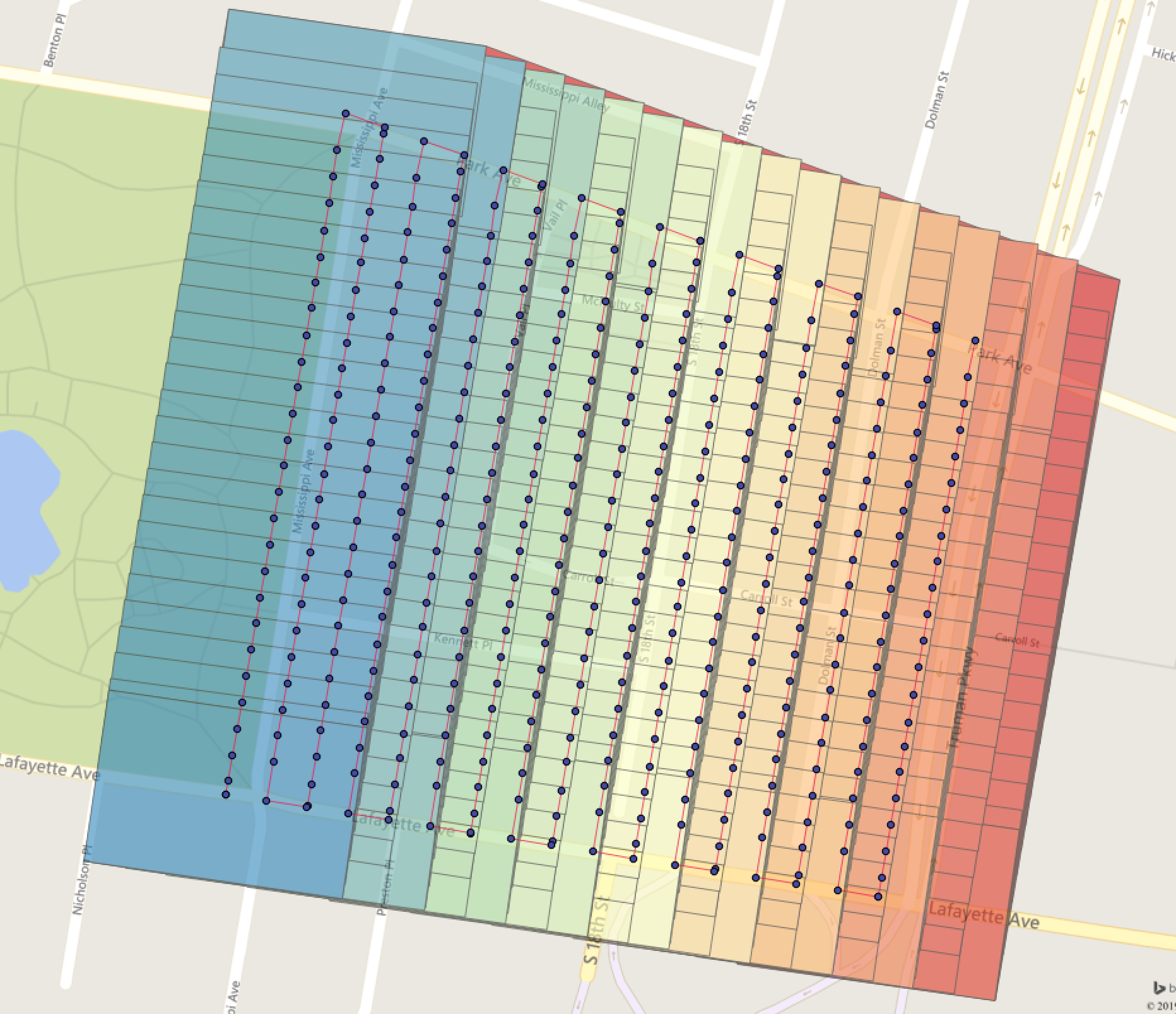
The geojson example is here:
https://drive.google.com/file/d/1RhSlY9KL2NYpnnVyNqI5c6cLzC0YWMTj/view?usp=sharing
spifftek70
on 31 Aug 2019
Yes! Would be even better if the overlap / camera positions were taken from the structure from motion process, but even if the data is from EXIFs it could be useful in a report.
 pierotofy
on 31 Aug 2019
pierotofy
on 31 Aug 2019
I'm still working out some bugs. I'll post a GitHub link on it soon.
spifftek70
on 31 Aug 2019
The only issue is that it needs to know the sensor width and height. Unfortunately, that information isn't in the exif or any other source that I know of. You have to look it up and pass it in.
spifftek70
on 31 Aug 2019
There’s a database of camera sensors here: https://github.com/openMVG/CameraSensorSizeDatabase/blob/master/sensor_database_detailed.csv
There’s not many drones on there but it’d be nice to contribute.
 daz
on 31 Aug 2019
daz
on 31 Aug 2019
perfect
spifftek70
on 31 Aug 2019
pierotofy
on 31 Aug 2019
The code I have is not as accurate as I'd like. It doesn't take into account the pitch, yaw, roll.
for that, I could actually use a bit of help with translating this code from LaTeX to Python.
After that, I can plug and play it.
spifftek70
on 1 Sep 2019
That calculation on SO is not correct. I messed around with it a while ago, unless you’re doing proper matrix maths you need to completely ignore the pitch and yaw of the gimbal and just pretend the images are perfect nadir.
daz
on 1 Sep 2019
@daz - What about this one?
spifftek70
on 1 Sep 2019
I’m not good at maths so I can’t be sure, but it looks like it could doing the right kind of things lol. It’s ignoring lens distortion but that’s not super important. Here’s an in-depth article, for a footprint we only need the four corners but it’s interesting anyway.
daz
on 1 Sep 2019
Here’s the breakdown we want. Great article: http://rijesha.com/blog/aerial-cam-footprint/
daz
on 1 Sep 2019
@daz - that is the tutorial to the repo I posted the link to.
spifftek70
on 1 Sep 2019
yeah, this guide is failing me. Can somewhere check my math?
#  gimx = GimbalPitchDegree
#  gimy  = GimbalRollDegree
#  gimz = GimbalYawDegree
#  fimx = AcftPitchDegree
#  fimy = AcftRollDegree
#  fimz = AcftYawDegree
#  fl = Focal length
#  cds1 = Longitutde, Latitude


def new_gross(cds1, alt, fl, gimx, gimy, gimz, fimx, fimy, fimz):
    sw = 8  # Sensor Width
    sh = 5.3  # Sensor Height
    fov_x = 2 * degrees(atan(sw / (2 * fl)))
    fov_y = 2 * degrees(atan(sh / (2 * fl)))
    TR = np.quaternion((-fov_x / 2), (fov_y / 2), 0)
    TL = np.quaternion((fov_x / 2), (fov_y / 2), 0)
    BR = np.quaternion((-fov_x / 2), (-fov_y / 2), 0)
    BL = np.quaternion((fov_x / 2), (-fov_y / 2), 0)
    gimRot = np.quaternion(gimx, gimy, gimz)
    acRot = np.quaternion(fimx, fimy, fimz)
    TR1 = acRot * (gimRot * TR)
    TL1 = acRot * (gimRot * TL)
    BR1 = acRot * (gimRot * BR)
    BL1 = acRot * (gimRot * BL)
        crn = [TR1, TL1, BL1, BR1]
    coords = []
    for c in crn:
        bod = post_quat(cds1, c, alt)
        coords.append(bod)
    print("CORDS", coords)
    crn = {"type": "Polygon", "coordinates": [[coords[0], coords[1], coords[2], coords[3], coords[0]]]}
    crn = rewind(crn)
    print(crn)
    return


def gross_crds(lat, lng):
    cds1 = utm.from_latlon(lat, lng)
    return cds1[0], cds1[1]


def post_quat(cent, crn, alt):
    crn2 = quaternion.as_euler_angles(crn)
    x = crn2[0]  # GimbalPitchDegree
    y = crn2[1]  # GimbalRollDegree
    z = crn2[2]  # GimbalYawDegree

    dx = (math.tan(y) * alt)
    dy = (math.tan(x) * alt)
    dutmx = dx * (math.cos(z)) - dy * (math.sin(z))
    dutmy = -dx * (math.sin(z)) - dy * (math.cos(z))
    utmx1 = cent[1] + dutmx
    utmy1 = cent[0] + dutmy
    print("xx", cent[1], dutmx)
    print("YY", cent[0], dutmy)
    # print("XX", utmx1, "YY", utmy1, cent[2], cent[3])
    coords = utm.to_latlon(utmx1, utmy1, cent[2], cent[3])
    return [coords[0], coords[1]]
I haven't tested your code yet, but don't we disregard aircraft roll/pitch/yaw? I vaguely remember reading that the DJI GimbalXXXDegrees EXIF represents real world, regardless of the drone.
daz
on 2 Sep 2019
@daz I think you're right:
Gimbal Roll Degree : +0.00
Gimbal Yaw Degree : +91.10
Gimbal Pitch Degree : -89.90
Flight Roll Degree : +5.40
Flight Yaw Degree : +89.20
Flight Pitch Degree : -15.30
From Phantom3 exif
jokd
on 2 Sep 2019
Good catch. But while I do use DJI (good products), I don't think everyone does... Let me see what I can do. A bit of logic around the gimbal or sensor model can account for that logic.
spifftek70
on 2 Sep 2019
So I'm making progress at this, but I'm not there yet. The bright green polygon is what I have from this new code that accounts for the look angle from NADIR. The other polygons are from older code that requires perfect NADIR and thus is a bit less accurate.
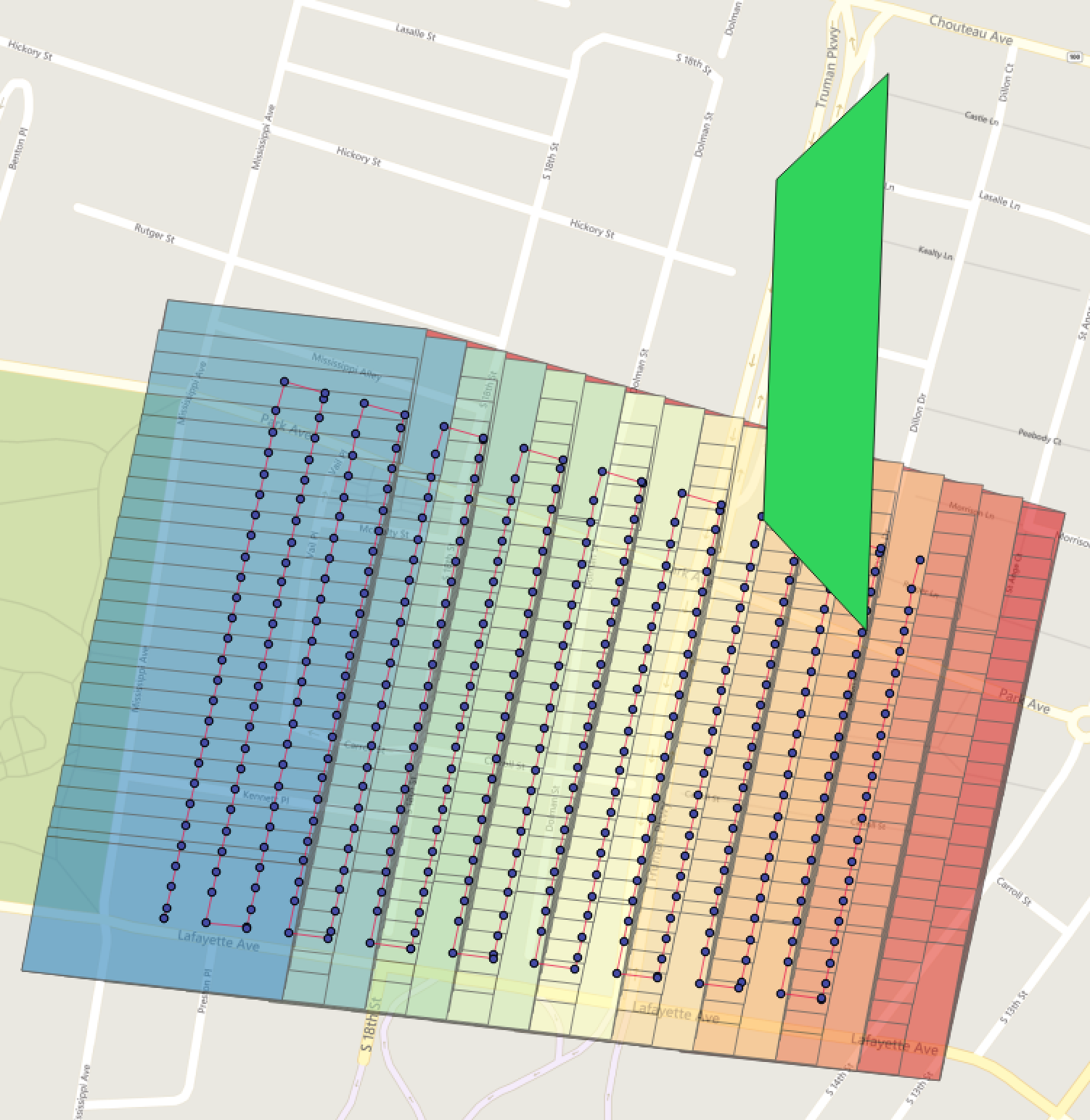
Here's the code (revised)
#  gimp = GimbalPitchDegree
#  gimr  = GimbalRollDegree
#  gimy = GimbalYawDegree
#  fl = Focal length
#  cds1 = Longitutde, Latitude

def new_gross(cds1, alt, fl, gimp, gimr, gimy, fimx, fimy, fimz):
    sw = 8
    sh = 5.3
    fov_x = 2 * degrees(atan(sw / (2 * fl)))
    fov_y = 2 * degrees(atan(sh / (2 * fl)))
    TR = np.quaternion((fov_x / -2), (fov_y / 2), 0)
    TL = np.quaternion((fov_x / 2), (fov_y / 2), 0)
    BR = np.quaternion((fov_x / -2), (fov_y / -2), 0)
    BL = np.quaternion((fov_x / 2), (fov_y / -2), 0)
    gimRot = np.quaternion(gimp, gimr, gimy)
    # acRot = np.quaternion(fimx, fimy, fimz)
    TR1 = gimRot * TR
    TL1 = gimRot * TL
    BR1 = gimRot * BR
    BL1 = gimRot * BL
    crn = [TR1, TL1, BL1, BR1]
    coords = []
    for c in crn:
        bod = post_quat(cds1, c, alt)
        coords.append(bod)
    crn = {"type": "Polygon", "coordinates": [[coords[0], coords[1], coords[2], coords[3], coords[0]]]}
    crn = rewind(crn)
    print(crn)
    return


def gross_crds(lat, lng):
    cds1 = utm.from_latlon(lat, lng)
    return cds1[0], cds1[1]


def post_quat(cent, crn, alt):
    crn2 = quaternion.as_float_array(crn)
    p = crn2[0]  # GimbalPitchDegree
    r = crn2[1]  # GimbalRollDegree
    y = crn2[2]  # GimbalYawDegree
    dx = alt * math.tan(math.radians(r))
    dy = alt * math.tan(math.radians(p))

    utmx = dx * math.cos(math.radians(y)) - dy * math.sin(math.radians(y)) + 150
    utmy = -dx * math.sin(math.radians(y)) - dy * math.cos(math.radians(y)) + 150
    utmx1 = cent[0] + utmx
    utmy1 = cent[1] + utmy
    coords = utm.to_latlon(utmx1, utmy1, cent[2], cent[3])
    return [coords[1], coords[0]]
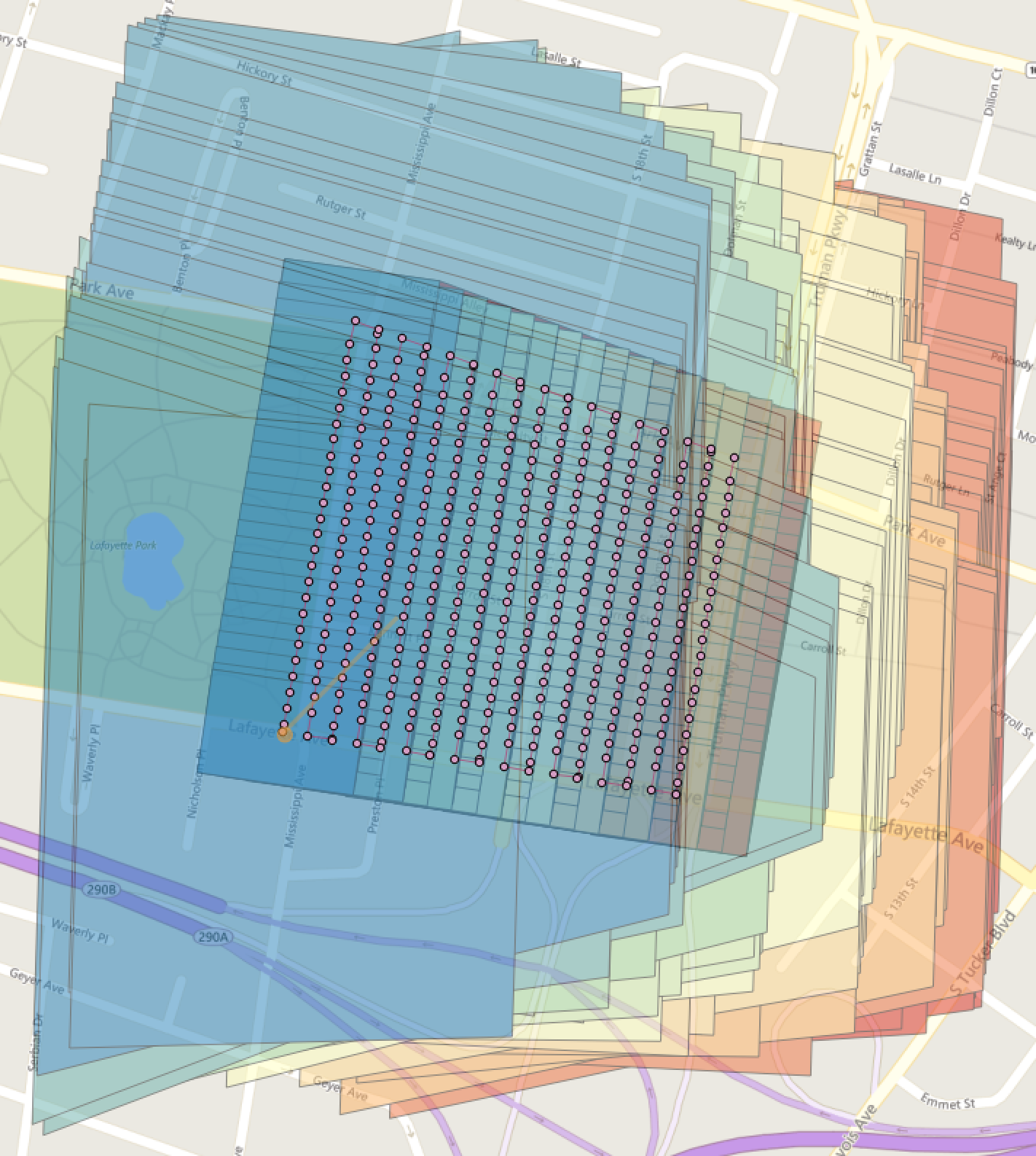
Making more progress. The smaller polygons are my previous script using only nadir and image width/height. The larger is code from that tutorial...
spifftek70
on 3 Sep 2019
@spifftek70
From the code snippet you posted it looks like you aren’t doing anything with “alt” (altitude). Perhaps that would explain why the scale of your latest picture looks off.
 jpwhitney
on 3 Sep 2019
jpwhitney
on 3 Sep 2019
dx and dy uses alt, but what is the + 150 for?
jokd
on 3 Sep 2019
I took that off. it's for a specific viewer
spifftek70
on 3 Sep 2019
@spifftek70
From the code snippet you posted it looks like you aren’t doing anything with “alt” (altitude). Perhaps that would explain why the scale of your latest picture looks off.
@jpwhitney, It uses alt, as @jokd pointed out.
spifftek70
on 3 Sep 2019
I've created a repo HERE
spifftek70
on 3 Sep 2019
@jokd & @spifftek70
Oh right, I was looking in the wrong place. Just going for low hanging fruit I suppose.
Here’s another hopefully more well informed guess. It looks like DJI EXIF data used altitude at meters above sea level. So in essence your code projects the image extents onto a surface at sea level, not at the ground level you are interested in.
Could it be so simple? Perhaps you already account for this somewhere. I only briefly looked over that repo on my phone, but am looking forward to going over it more carefully. I think this will be a great contribution. It seems really close!
jpwhitney
on 4 Sep 2019
Hi all,
I am merely an end-user and can only contribute in the sense of confirming DJI's EXIF data. Altitude is definitely in MASL:
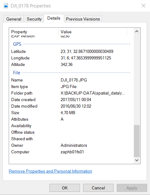
rionlerm
on 4 Sep 2019
There's a Relative Altitude field, relative to launch location. For the tools I've made, I have a workflow to take a photo at launch point. Then for the rest of the photos, use EXIF relative altitude and Google terrain elevation API to get an approximate AGL value for each image.
X5S

GPS Altitude Ref                : Above Sea Level
Absolute Altitude               : +21.60
Relative Altitude               : +32.10
GPS Altitude                    : 21.5 m Above Sea Level

Mavic 2 Pro

GPS Altitude Ref                : Above Sea Level
Absolute Altitude               : +57.38
Relative Altitude               : +108.60
GPS Altitude                    : 57.3 m Above Sea Level

XT

GPS Altitude Ref                : Above Sea Level
Absolute Altitude               : -36.431530
Relative Altitude               : 44.400002
GPS Altitude                    : 0 m Above Sea Level
@daz - I am using relative altitude. Using a good DEM is an option. However, for these test images, the terrain elevation is pretty consistent.... ie flat.
spifftek70
on 4 Sep 2019
I think this is starting to be addressed by https://github.com/uav4geo/DroneDB/. I will close this for now, but if there is still interest, we can re-open.
smathermather
on 14 Apr 2020
Related issues
smathermather
·
5Comments
 linusmartensson
·
5Comments
linusmartensson
·
5Comments
 brookjason
·
4Comments
pierotofy
·
3Comments
pierotofy
·
4Comments
brookjason
·
4Comments
pierotofy
·
3Comments
pierotofy
·
4Comments
Most helpful comment
Would an output like this be appropriate? It's a geojson with overall mission boundary (polygon), camera trigger points (points), Image tile boundaries (polygons), and flightpath (linestring).
The geojson example is here:
https://drive.google.com/file/d/1RhSlY9KL2NYpnnVyNqI5c6cLzC0YWMTj/view?usp=sharing