Mne-python: DOC: Reporting filter properties
Concerning filtering, in Wiedmann et al. (2015) they recommend to report:
All filter parameters, including filtertype (high-pass, low-pass, band-pass, band-stop, FIR, IIR), cutoff frequency (including definition), filter order (or length), roll-off or transition bandwidth, passband ripple and stopband attenuation, filter delay(zero-phase, linear-phase, non-linear phase) and causality, and direction of computation (one-pass forward/reverse,or two-pass forward and reverse) must be reported
Checking the MNE documentation and specifically the background on filtering and tutorial, there are some questions that I have:
What is the definition of the cutoff frequency by the filters used in MNE? In the docstring of
create_filterit say that -6dB is the middle of the transition window. Does that mean that in MNE, the middle of the transition window is the "half-amplitude" cutoff? (as opposed to half-power)Filter length and transition bandwidth are being printed upon calling
raw.filter(), which is nice - but how would I compute them without having to filter data and copying the values from the console?I haven't seen a method to calculate stopband attenuation and passband ripple in MNE. Did I miss it? Is there some straight forward way using scipy?
Does anyone besides me think that these outputs would be a nice addition to the raw.info? Maybe providing filter information as a dictionary containing the meta data named above in addition to the frequencies which are the only thing that is specified currently ... opinions?
 sappelhoff
All 13 comments
Someone needs to check all of these things (preferably by showing them by updating the tutorial) because I can't remember offhand, but yes what you say sounds right. Do you have the time / knowledge to check and update it?
Filter length and transition bandwidth are being printed upon calling raw.filter(), which is nice - but how would I compute them without having to filter data and copying the values from the console?
mne.filter.create_filter will create the filter and give these log messages. You can pass it a dummy data array. Actually we should proably make data=None a possibility, meaning "skip length checks/warnings".
I haven't seen a method to calculate stopband attenuation and passband ripple in MNE. Did I miss it? Is there some straight forward way using scipy?
This would be another great addition to the tutorial. We use standard scipy.signal.firwin design, so these properties are dependent upon the window used in design. In theory this might be documented in SciPy. If not, they should probably be added there. They are standard windows so the values should be listed online somewhere, probably on Wikipedia. We should make a table...
Does anyone besides me think that these outputs would be a nice addition to the raw.info?
Yes in principle but in practice there is a limited set of items we can put in raw.info and the filter parameters are not included. If you want you can modify raw.info['description'] string to include this information.
 larsoner
on 23 May 2018
larsoner
on 23 May 2018
I'll see what I can do ... I don't have a lot of knowledge about filters though, .. and the scipy docstring for firwin does not specify details about the cutoff either. So maybe I will post a question to stackexchange signal processing or stackoverflow for help ...
related: The docstring "Returns" seems to be wrong. It actually returns h, the filter coefficients:
sappelhoff
on 24 May 2018
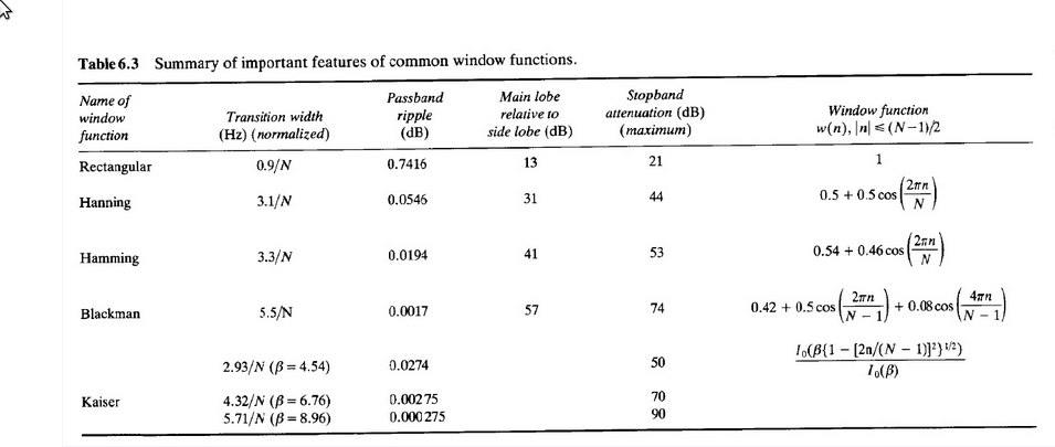
Here is a table, the "peak approximation error" here is really the stop-band attenuation (e.g., 53 dB for Hamming) which matches the table in Ifeachor and Jervis p357 (except Blackman attenuation, which I&J list as 75 dB):
Filters designed using windowed FIR design have equal pass-band and stop-band ripple, so giving the attenuation effectively gives you those numbers, too.
larsoner
on 24 May 2018
That's already great. Do you suggest that I copy the table (Ifeachor and Jervis) into the updated version of the "Background on Filtering" example?
I'd do that together with a short intro on Wiedmann's recommendations on what to report of filters ... then followed by a code block on how to get transition bandwidth and filter length.
Then the only missing information at this point is:
- are the
scipy.signal.firwinfilter cutoffs specified in half-amplitude or half-power at the middle of the transition band? - source that "Filters designed using windowed FIR design have equal pass-band and stop-band ripple" (the table actually suggests otherwise?)
- all of the above information for IIR filters?
sappelhoff
on 24 May 2018
are the scipy.signal.firwin filter cutoffs specified in half-amplitude or half-power at the middle of the transition band?
I don't know, someone needs to check. But I think it's half-amplitude.
source that "Filters designed using windowed FIR design have equal pass-band and stop-band ripple" (the table actually suggests otherwise?)
Ifeachor and Jervis 2nd ed p 356:
We also note that a filter designed by the window method has equal
passband and stopband ripples, that is δp = δs.
source that "Filters designed using windowed FIR design have equal pass-band and stop-band ripple" (the table actually suggests otherwise?)
This bit is understandably tricky. The scalar passband ripple δp is expressed in dB as 20 * log10(1+δp), but the scalar stopband ripple δs is expressed in dB as -20 * log10(δs). So if we know that our stopband attenuation is 53 dB (Hamming) then δs = 10 ** (53 / -20.), which means that the passband deviation should be 20 * np.log10(1 + 10 ** (53 / -20.)) == 0.019423550886325903, as in the table.
I think my I&J (2nd ed?) might have a typo, as it lists the attenuation as 75 instead of 74, which gives a passband ripple of 0.0015 instead of 0.0017.
all of the above information for IIR filters?
IIR filters have no defined stop band, so they need to be specified differently. In general stating the filter order, type of filter (e.g., Butterworth), filter method (forward or forward-backward), cutoff frequency, and sample rate should be sufficient to recreate the filter coefficients. (In practice, though, whether you use a method like second-order sections or direct IIR filtering can matter for filter stability.)
larsoner
on 24 May 2018
... and yes copying that table (with ref) would be great!
larsoner
on 24 May 2018
... would be super cool if we had a function to automatically add a fully specified methods section report from filter settings :)
 jona-sassenhagen
on 28 May 2018
jona-sassenhagen
on 28 May 2018
This could be added to the logger.info of create_filter
larsoner
on 29 May 2018
This could be added to the logger.info of create_filter
You mean passband ripple and stopband attenuation?
sappelhoff
on 29 May 2018
Yes, plus whatever else we are supposed to report (e.g., half-amp / half-power point)
larsoner
on 29 May 2018
... ideally as a fully formatted text, copy and paste ready :)
jona-sassenhagen
on 29 May 2018
Reopening this since @bmaess brought up the idea again, and noted we should do this for IIR filters, as well.
larsoner
on 9 May 2019
Concerning the -3dB versus -6dB problem: Both is 'correct' and it offers a very elegant way to publish the cutoff limits for the forward-backward filters: design the filter using the -3dB cutoff and in case of the two-pass filter - present the cutoff values as -6dB values. If the corresponding report also mentions the damping of the cutoff, there should be no problem. A bandpass designed as a single-pass 5th order butterworth with -3dB cutoffs at 8 and 12 Hz becomes a two-pass filter of 10th order butterworth with -6dB cutoffs at 8 and 12 Hz.
 bmaess
on 9 May 2019
bmaess
on 9 May 2019
Related issues
 annesodub
·
3Comments
annesodub
·
3Comments
 hoechenberger
·
6Comments
larsoner
·
5Comments
hoechenberger
·
6Comments
larsoner
·
5Comments
 timonmerk
·
5Comments
sappelhoff
·
6Comments
timonmerk
·
5Comments
sappelhoff
·
6Comments