Mbed-os: SPIFBLockDevice constantly encounters "Bad Block" when using LFS
Description
I'm trying to write a file to LFS mounted upon a SPIFBlockDevice. The SPIF trace is indicating that after exactly two writes (of 64 Bytes each), my eeprom experiences a "bad block" and then calls for an erase (of 4096 Bytes). This is pretty unfortunate because it essentially means increments of 4096 bytes of address space for ever 128 Bytes of data. Am I missing something in my configuration that's causing this perhaps?
Issue request type
Target: UBLOX_EVK_ODIN_W2
Toolchain: GCC_ARM 7.3.1
Tool: mbed-cli
Vers: cfa7938a4d (HEAD, tag: mbed-os-5.12.2)
This is a sample of the trace showing all the looping behaviour described above:
[INFO][SPIF]: DEBUG: erase - addr: 16384, in_size: 4096
[DBG ][SPIF]: DEBUG: erase - addr: 16384, size:4096, Inst: 0x20h, chunk: 4096 ,
[DBG ][SPIF]: DEBUG: erase - Region: 0, Type:0
[INFO][SPIF]: INFO: Erase Inst: 0x20h, addr: 16384, size: 4096
[DBG ][SPIF]: DEBUG: program - Buff: 0x2001e070h, addr: 16384, size: 64
[DBG ][SPIF]: DEBUG: program - Buff: 0x2001e070h, addr: 16448, size: 64
[INFO][SPIF]: INFO Read - Inst: 0x3h
[INFO][SPIF]: INFO Read - Inst: 0x3h
lfs debug:617: Bad block at 4
[INFO][SPIF]: DEBUG: erase - addr: 20480, in_size: 4096
[DBG ][SPIF]: DEBUG: erase - addr: 20480, size:4096, Inst: 0x20h, chunk: 4096 ,
[DBG ][SPIF]: DEBUG: erase - Region: 0, Type:0
[INFO][SPIF]: INFO: Erase Inst: 0x20h, addr: 20480, size: 4096
[INFO][SPIF]: INFO Read - Inst: 0x3h
[DBG ][SPIF]: DEBUG: program - Buff: 0x2001e070h, addr: 20480, size: 64
[DBG ][SPIF]: DEBUG: program - Buff: 0x2001e070h, addr: 20544, size: 64
[INFO][SPIF]: INFO Read - Inst: 0x3h
[INFO][SPIF]: INFO Read - Inst: 0x3h
lfs debug:617: Bad block at 5
[INFO][SPIF]: DEBUG: erase - addr: 24576, in_size: 4096
This is the declaration of the SPIF block device: (n.b. I didn't specify a value for freq, and thus the default of 40000000 is being used)
SPIFBlockDevice bd(D11, D12, D13, D10);
This is my initialisation of the block device and LFS:
    tr_debug("Initialising FirmwareUpdater... ");
    tr_debug("Initialising block device... ");
    int8_t err = _bd->init();
    tr_debug("%s", (err ? "Fail" : "OK"));
    lfs_size_t read_size = _bd->get_read_size();
    lfs_size_t prog_size = _bd->get_program_size();
    lfs_size_t block_size = _bd->get_erase_size();
    lfs_size_t lookahead = 256; //currently not doing anything with these parameters
    tr_debug("read_size: %lu", read_size);
    tr_debug("prog_size: %lu", prog_size);
    tr_debug("block_size: %lu", block_size);
    tr_debug("lookahead: %lu", lookahead);
    tr_debug("Mounting the filesystem... ");
    err = _fs.mount(_bd);
    tr_debug("%s", (err ? "Fail" : "OK"));
    if (err) {
        // Reformat if can't mount the filesystem
        // this should only happen on corruption/first boot
        tr_debug("No filesystem found, formatting... ");
        err = _fs.reformat(_bd);
        tr_debug("%s", (err ? "Fail" : "OK"));
        if (err) {
            tr_error("error: %s (%d)", strerror(-err), err);
            return -1;
        }
    }
And finally this is the code where content is actually being written to my file:
_file = fopen(FULL_UPDATE_FILE_PATH, "wb");
// this callback is used to handled chunked data from my source
void FirmwareUpdaterHTTP::body_callback(const char * data, uint32_t data_len)
{
    // Write data to file
    size_t size = fwrite(data , 1, data_len, _file);
    _write_progress += size;
    tr_info("Progress: %lu ", _write_progress);
}
For what it's worth, I'm using this eeprom: IS25LP032D
Datasheet: http://www.issi.com/WW/pdf/25LP-WP032D.pdf
[x] Question
[ ] Enhancement
[ ] Bug
 DrynnBavis
All 6 comments
@geky Not sure if you've heard of others having issues with LFS on SPIF devices, but I'd appreciate any advice you can throw my way!
DrynnBavis
on 7 Jun 2019
This is pretty unfortunate because it essentially means increments of 4096 bytes of address space for ever 128 Bytes of data.
On a Flash you can set one byte from 0xFF to 0x00, but to reset a byte from 0x00 to 0xFF you need to erase the whole sector (in your case 4K).
https://electronics.stackexchange.com/questions/69234/what-is-the-difference-between-flash-memory-and-eeprom/69275
https://electronicsforu.com/resources/learn-electronics/eeprom-difference-flash-memory
https://www.microchip.com/forums/m1007157.aspx
This is the declaration of the SPIF block device: (n.b. I didn't specify a value for freq, and thus the default of 40000000 is being used)
The default frequency of 40MHz is a bad trap, most of the MCUs, which have less then 80MHz can't communicate on SPI with 40MHz (Prescaler for SPI Clock is typically Div2 -> half Clock Speed).
I made a quick look in the datasheet for your MCU and It seems that the maximum SPI-Clock depends which SPI will be selected:
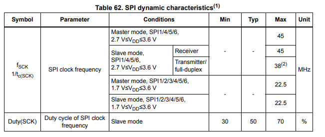
I suggest you select 1MHz for SPI-Clock, if it works increase it to 22.5MHz and so on.
If it isn't the SPI-Clock speed (which is highly possible, because it seems you are able to communicate with the Flash), try this example https://os.mbed.com/docs/mbed-os/v5.12/apis/spi-flash-block-device.html and verify that this will work.
 DBS06
on 7 Jun 2019
DBS06
on 7 Jun 2019
I suggest you select 1MHz for SPI-Clock, if it works increase it to 22.5MHz and so on.
I've played around with 1MHz, 10MHz, 22.5MHz, 40MHz, and 45MHz. When using 45, I can no longer communicate with the eeprom, ERROR: init - _verify SFDP signature and version Failed.
Using the others all result in the partial success described above but ultimately still fail with constant "bad blocks" being seen. With these configurations I'd see about 1.8KB being written before hard faulting with this error:
++ MbedOS Error Info ++
Error Status: 0x80FF0144 Code: 324 Module: 255
Error Message: Assertion failed: pcache->block == 0xffffffff
Location: 0x8027AA9
File: libs/mbed-os/features/storage/filesystem/littlefs/littlefs/lfs.c+183
Error Value: 0x0
Current Thread: application_unnamed_thread  Id: 0x2000BCCC Entry: 0x802B545 StackSize: 0x2000 StackMem: 0x20015748 SP: 0x200169B8
For more info, visit: https://mbed.com/s/error?error=0x80FF0144&tgt=UBLOX_EVK_ODIN_W2
-- MbedOS Error Info --

= System will be rebooted due to a fatal error =
So it seems likely that we can conclude the clock speed isn't the issue here (though I'm still glad we checked it!).
Moving on, I've tried the example code in the api documentation you linked. It works, as I expected it to. I don't believe there's something wrong here with the block device, but rather the way LFS is behaving on SPIFBD. You can actually see in my first block of code in my first post that the "bad block" message is coming from lfs debug. After enough of these it ultimately ends up in the hard fault pasted above.
DrynnBavis
on 7 Jun 2019
That is strange.
The "bad block" message indicates that LittleFS detected an error in the data it wrote to the block device. This triggers an erase as LittleFS tries to move the data from the bad block to a block it believes to be good.
The error you are seeing looks a lot like some sort of bus corruption that is causing writes to fail. The SPI flash protocol doesn't have any sort of error detection, so LittleFS ends up being the one who detects the error.
I think @DBS06 was right to think it was a clock speed issue, but from your experiments that looks unlikely. What board are you using? It may be an issue with the SPI driver itself.
It could also be excessive noise or a power issue, though if it is very consistent those get less likely.
It may be worth writing a small application that writes a set of random data to the block device and checks for errors. That would rule out (or prove) a filesystem issue.
 geky
on 11 Jun 2019
geky
on 11 Jun 2019
Just an update, for my application we've decided not to use a file system (for reasons irrelevant to this problem). I've been using the SPIF device as just a flat block device and have encountered/fixed a few problems.
On the software level: the SPIF Block Device driver uses a mask on the bd->erase(addr, length) function to filter erase lengths to be a multiple of the block size (min erase size) of 4096. See here. After masking, my addr was always turning into just 0, so essentially any erase command would always just erase at address 0. I think this is because it was interpreting this as an int (likely 16 bit on my side rather than the required 32). I fixed this by specifying that the mask type to be uint32_t in the following:
spif_bd_error SPIFBlockDevice::_spi_send_erase_command(int erase_inst, bd_addr_t addr, bd_size_t size)
{
    tr_info("INFO: Erase Inst: 0x%x, addr: 0x%llx, size: %llu", erase_inst, addr, size);
    uint64_t BLOCK_MASK = 0x00FFF000;
    uint64_t block_addr = (addr & BLOCK_MASK);
    tr_info("Post-bitwise-and address: 0x%llx", block_addr);
    _spi_send_general_command(erase_inst, block_addr, NULL, 0, NULL, 0);
    return SPIF_BD_ERROR_OK;
}
(side note, I wouldn't mind opening a PR to fix this issue. Do you guys @ciarmcom @DBS06 have a contribution help page?)
Then on the hardware side, I noticed some odd behaviour on the Chip Enable line so I added a pull-up to 3v3 and that fixed any problems I had of reading SDFP data at the beginning. Additionally, I actually totally forgot about an SD card I had previously plugged into my MCU. Even though it has its own chip select line, I suspect it was somehow fuzzing up the MISO line. Check out this data sample I grabbed from with the SD card in and no pullup:
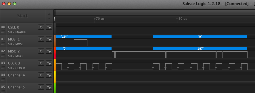
Anyway, after these fixes it's really clean. I've written to the eeprom and rebooted the eeprom about 10 times now and not a single error has been seen. My thanks to those involved, @geky good idea to check the bus lines!
DrynnBavis
on 13 Jun 2019
Thanks for creating a PR! Glad to see you were able to figure out the issue.
geky
on 21 Jun 2019
Related issues
 ccchang12
·
4Comments
ccchang12
·
4Comments
 chrissnow
·
4Comments
chrissnow
·
4Comments
 0xc0170
·
3Comments
0xc0170
·
3Comments
 toyowata
·
4Comments
toyowata
·
4Comments
 bulislaw
·
3Comments
bulislaw
·
3Comments
Most helpful comment
On a Flash you can set one byte from 0xFF to 0x00, but to reset a byte from 0x00 to 0xFF you need to erase the whole sector (in your case 4K).
https://electronics.stackexchange.com/questions/69234/what-is-the-difference-between-flash-memory-and-eeprom/69275
https://electronicsforu.com/resources/learn-electronics/eeprom-difference-flash-memory
https://www.microchip.com/forums/m1007157.aspx
The default frequency of 40MHz is a bad trap, most of the MCUs, which have less then 80MHz can't communicate on SPI with 40MHz (Prescaler for SPI Clock is typically Div2 -> half Clock Speed).

I made a quick look in the datasheet for your MCU and It seems that the maximum SPI-Clock depends which SPI will be selected:
I suggest you select 1MHz for SPI-Clock, if it works increase it to 22.5MHz and so on.
If it isn't the SPI-Clock speed (which is highly possible, because it seems you are able to communicate with the Flash), try this example https://os.mbed.com/docs/mbed-os/v5.12/apis/spi-flash-block-device.html and verify that this will work.