Marlin: SKR 1.4 Turbo PT100 INA826 TEMP_SENSOR_0 = 21 Issue
Bug Description
Marlin 2.0.6 & Marlin Bugfix-2.0.x (as of 9/2/2020) on a BTT SKR 1.4 Turbo with an PT100 temp sensor using an E3D Amplifier Board (INA826) and the 4.7k resistor removed on the SKR TH0.
When setting TEMP_SENSOR_0 = 21 (3.3v Logic): I am getting a temperature reading of "1". Switching to TEMP_SENSOR_0 = 20 (5v logic), I get a more-normal reading of 24-25c (ambient is 22c), but the temp seems to not be correct on the hot end.
My Configurations
Steps to Reproduce
- TEMP_SENSOR_0 = 21 in configuration.h
- Remove 4.7k resistor from TH0 on SKR 1.4 Turbo
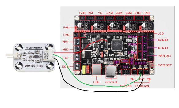
- Connect PT100 Amplifier board as seen here:
Expected behavior: Temperature reading of +-1degree from ambient
Actual behavior: Temperature reading "1"
 LightTribe-art
All 19 comments
I think the issue is that the INA826 is getting 3.3v input voltage. I moved it input voltage (red above) to a 5v source and it seems to be working correctly with TEMP_SENSOR_0 = 21.
Leaving this until someone can confirm the this is the correct approach.
LightTribe-art
on 3 Sep 2020
same results here with an INA826 board (e3d clone) using the 3.3V from the SWD port.
thermistor_21.h does a linear conversion of the 5V lookup table to 3.3V.
My first shot would be to change the lookup table itself.
I use the same workaround by providing 5V. It should only be a tiny risk to fry the ADC port of the LPC1769 as the ADC is not 5V tolerant and the INA826 could in theory provide >3.3V at very high temperatures (>600°C).
EDIT: the workaround might lead to excessive error above room temperature as a 5V supply and the 3V3 ADC reference of the LPC1769 are leading to wrong look-up table references.
https://community.nxp.com/t5/LPCXpresso-IDE/5v-tolerant-inputs-on-lpc1769/m-p/527932
https://wiki.e3d-online.com/E3D_PT100_Amplifier_Documentation
 Quas7
on 3 Sep 2020
Quas7
on 3 Sep 2020
It should only be a tiny risk to fry the ADC port of the LPC1769 as the ADC is not 5V tolerant and the INA826 could in theory provide >3.3V at very high temperatures (>600°C).
This was my conclusion as well.
LightTribe-art
on 3 Sep 2020
Looks like the conversion in thermistor_21.h increases the ADC values for given temperatures instead of reducing them.
This would explain, why we see a '1' at room temp.
Exchanging line 27 in thermistor_21.h
define OV_SCALE(N) (float((N) * 5) / 3.3f)
with
define OV_SCALE(N) (float((N) * 3.3f) / 5)
should do the trick. Will test tomorrow maybe.
EDIT: ... resulted in 181°C at 22°C room temp. Does not fix it (see below why).
Attached my draft for the table (untested and derived from the e3d 5V table).
EDIT3:
corrected table with INA @3V3 output voltages and corresponding ADC values ((identical to 5V)
Lookup_table_for_INA826_at_3V3_corrected.xlsx
EDIT2:
I think, I did the same mistake as the programmer of the conversion.
The lookup-table for the ADC should not change at all. The the ADC reference voltage is still the same as the supply of the INA826 at everything is ratiometric. Therefore, using 3V3 supply with the 5V ADC table from TEMP_Sensor 20 should be totally fine.
On the other hand, using the workaround with 5V and the ADC on 3V3 reference should result in quite an error! I did not print yet with this setup to be honest.
Quas7
on 3 Sep 2020
Therefore, using 3V3 supply with the 5V ADC table from TEMP_Sensor 20 should be totally fine.
When I use a 3.3v input and used TEMP_SENSOR_0 = 20, I would get a reading of about 3-4 degrees above ambient. When I heated the hot end to a known good temp, it seemed to be too cool. Admittedly, I don't have a accurate way to verify the temp.
I have tested:
3V3/20 - Ambient = +3-4 degree. Printing temp appeared too cold. Could use a more accurate method to verify.
3V3/21 - Ambient = 1
5V/20 - Seems OK (printing a test ATM)
5V/21 - Ambient > 170
LightTribe-art
on 3 Sep 2020
similar for me. With probe No. '20' @3V3 I get +3°C on the INA-PT100 compared to the NTC bed-probe.
I quickly heated now to setpoint 100°C and measured with a second PT100 probe. That results in +2°C offset for the INA-setup and I measure not inside the heating block as with the INA-PT100.
Therefore, I would consider this close enough for our purposes ;)
EDIT:
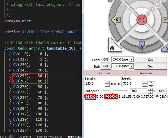
looking at the lookup table the room temperature error might result from a rounding issue.
There are 12.5%err in the rouding and that fits quite well to the 2-3°C mismatch around 25°C.
227, 1°C
236, 10°C (+9 counts)
245, 20°C (+9 counts)
253, 30°C (+8 counts)
262, 40°C (+9 counts)
Quas7
on 3 Sep 2020
it is getting obvious, that the description of thermistor 21 is misleading.
The comment should not be about the excitation voltage but about the ADC reference voltage.
- 20 : Pt100 with circuit in the Ultimainboard V2.x with 5v excitation (AVR)
- 21 : Pt100 with circuit in the Ultimainboard V2.x with 3.3v excitation (STM32 LPC176x....)
should be replaced by something like
- 20 : Pt100 with circuit in the Ultimainboard V2.x with mainboard ADC reference voltage = amplifier supply voltage
- 21 : Pt100 with circuit in the Ultimainboard V2.x with 3.3v ADC reference voltage (STM32, LPC176x....) and 5V amplifier board supply for increased temperature resolution
Quas7
on 3 Sep 2020
it is getting obvious, that the description of thermistor 21 is misleading.
The comment should not be about the excitation voltage but about the ADC reference voltage.* 20 : Pt100 with circuit in the Ultimainboard V2.x with 5v excitation (AVR) * 21 : Pt100 with circuit in the Ultimainboard V2.x with 3.3v excitation (STM32 \ LPC176x....)should be replaced by something like
* 20 : Pt100 with circuit in the Ultimainboard V2.x with mainboard ADC reference voltage = amplifier supply voltage

* 21 : Pt100 with circuit in the Ultimainboard V2.x with 3.3v ADC reference voltage (STM32, LPC176x....) and 5V amplifier board supply for increased temperature resolution
Yes, your suggestion is very much correct and should be in de source. I encountered this when designing a custom LPC1768 board for my Ultimaker 2.
I struggled a bit calculating a resistor dividers to correct for 5V -> 3.3V only to realize when both the amplifier voltage and the reference voltage both are the same (5V for AVR, or 3.3V for LPC1786) the resulting ADC values stay the same. My custom config uses thermistor type 20. Temperatures where validated by a K-type thermocouple.

 atoomnetmarc
on 11 Sep 2020
atoomnetmarc
on 11 Sep 2020
@atoomnetmarc please see https://github.com/MarlinFirmware/Marlin/pull/19246
 ellensp
on 11 Sep 2020
ellensp
on 11 Sep 2020
How about all the other 5v pins ? or neopixel or the 5v dc dc plug thing that you can buy ? would these not work ?
 dissocio0
on 18 Sep 2020
dissocio0
on 18 Sep 2020
or a lm2569 from a fan and lowering voltage, or from tft 35 v3 or tft35 v2.0 screen ? i see so many 5v ports what is the issue with those ? ground and a signal analog pin from exp 1,2,3 to program for signal
dissocio0
on 18 Sep 2020
@dissocio0
why do you think there is any issue to get clean 5V from the board?
the topic is about adc reference and INA reference (opamp supply) not about finding 5V.
Quas7
on 18 Sep 2020
i see so many 5v ports what is the issue with those ?
This works just fine. That's how I am running it currently. Technically there is a risk over over-volting the pin given it is 3v3 logic. This means above about 360 degrees, the output from the amp is getting close to maxing out the voltage capabilities of the pin. Not a problem for 99% of my needs.
LightTribe-art
on 19 Sep 2020
thinking again about the overvoltage.
It is almost impossible to damage the board (see above, way above, wayway above...).
But, much more importantly it is masking a thermal runaway, if overtemp is set beyond possible max ADC.
I was not aware that the INA setup could already max out the 3v3 ADC as early as 360C (Alumium heating blocks get soft/gummy around there).
In my opinion, a close to full scale readout on the ADC should trigger a overtemp shutdown. This should be set for all temp probes as fire prevention, if the user misconfigures overtemp.
Maybe there is already something öike this?
Quas7
on 19 Sep 2020
Становится очевидным, что описание термистора 21 вводит в заблуждение.
Комментарий не должен быть о напряжении возбуждения , а о Опорное напряжение АЦП.* 20 : Pt100 with circuit in the Ultimainboard V2.x with 5v excitation (AVR) * 21 : Pt100 with circuit in the Ultimainboard V2.x with 3.3v excitation (STM32 \ LPC176x....)следует заменить на что-то вроде
* 20 : Pt100 with circuit in the Ultimainboard V2.x with mainboard ADC reference voltage = amplifier supply voltage

* 21 : Pt100 with circuit in the Ultimainboard V2.x with 3.3v ADC reference voltage (STM32, LPC176x....) and 5V amplifier board supply for increased temperature resolution
Да, ваше предложение очень верное и должно быть в исходном коде. Я столкнулся с этим при разработке пользовательского LPC1768 платы для моего Ultimaker 2.
Я боролся немного расчета резистора делителей для коррекции 5V -> 3.3V только реализовать , когда оба напряжение усилителя и опорное напряжение , как один и тот же (5V для AVR или 3,3 В для LPC1786) результирующие значения АЦП остаются прежними. В моей пользовательской конфигурации используется термистор типа 20. Температуры подтверждены термопарой K-типа.
Hello! Can you tell me how you compiled a table of ADC values? I have a skr 1.3 PT100 and I output the ADC values to the terminal, but I don't understand how to convert them to a table. For example, at 35C, I have = 1031 in the terminal, although judging by the table it should be about 256, and I don't understand how to convert the ADC data from a term to data into a table.
 sashf228822
on 26 Sep 2020
sashf228822
on 26 Sep 2020
I noticed the same behavior. The debug output of ADC values differs greatly from the table values but the temperature calcualation is still correct. Therefore, no need to adjust the table. The ADC-debug values might already be converted to some voltage levels?
Quas7
on 26 Sep 2020
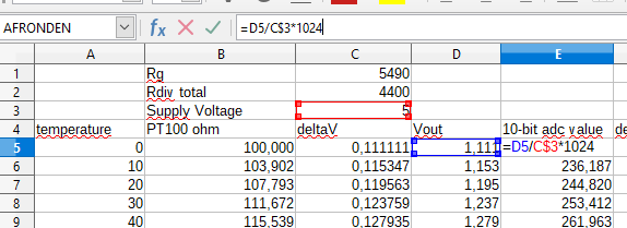
Sure! Here are the formulas for 5V. Essentially the power supply does not matter in the adc value because it is cancelled out in the formulas under the condition that the supply voltage of the amplifier is the same as the reference voltage of the adc.
rdiv total = r44+r45
rg = r57
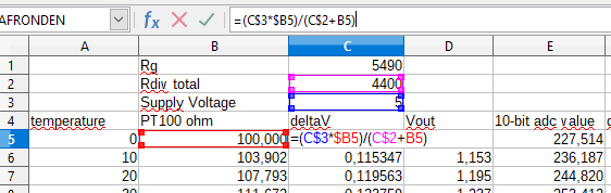
49k4 is a internal resistance of the ina826 (see datasheet under gain equation)
1024 is the adc maximum value
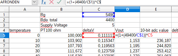
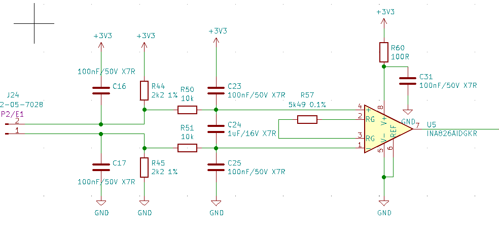
This is the 3v3 schematic for my amplifier:
atoomnetmarc
on 26 Sep 2020
Становится очевидным, что описание термистора 21 вводит в заблуждение.
Комментарий не должен быть о напряжении возбуждения , а о Опорное напряжение АЦП.* 20 : Pt100 with circuit in the Ultimainboard V2.x with 5v excitation (AVR) * 21 : Pt100 with circuit in the Ultimainboard V2.x with 3.3v excitation (STM32 \ LPC176x....)следует заменить на что-то вроде
* 20 : Pt100 with circuit in the Ultimainboard V2.x with mainboard ADC reference voltage = amplifier supply voltage

* 21 : Pt100 with circuit in the Ultimainboard V2.x with 3.3v ADC reference voltage (STM32, LPC176x....) and 5V amplifier board supply for increased temperature resolution
Да, ваше предложение очень верное и должно быть в исходном коде. Я столкнулся с этим при разработке пользовательского LPC1768 платы для моего Ultimaker 2.
Я боролся немного расчета резистора делителей для коррекции 5V -> 3.3V только реализовать , когда оба напряжение усилителя и опорное напряжение , как один и тот же (5V для AVR или 3,3 В для LPC1786) результирующие значения АЦП остаются прежними. В моей пользовательской конфигурации используется термистор типа 20. Температуры подтверждены термопарой K-типа.
Lookup_table_for_INA826_at_3V3_corrected.xlsx
Конечно! Вот формулы для 5В. По существу, блок питания не имеет значения в значение АЦП, потому что это компенсируется в формулах при условии, что напряжение питания усилителя является такой же, как опорное напряжение АЦП.
rdiv всего = r44 + r45
rg = r57
49k4 - это внутреннее сопротивление ina826 (см. Таблицу под уравнением усиления)
1024 - максимальное значение adc
Это схема моего усилителя 3v3:
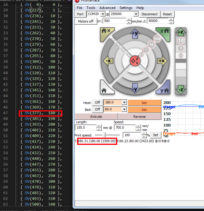
Thank you very much for your help! I did a research, and I realized that the values from the term ADC with the values in the table differ by 4 times, and I have the following justification - the bit width of the LPC1768 ADC is 12 bits, the bit width of the table is 10 bits, that is, the values of the ADC from the terminal must be divided by 2 ^ ( 12-10) = 4. For example, the temperature is 180, the ADC value is 1509, based on the formula, you need to divide it by 4, 1509/4 = 377.5, which ideally matches the table. With this information and a multi-monitor with the ability to measure temperature, I want to calibrate my thermistor by slightly correcting the table.
sashf228822
on 26 Sep 2020
This issue has had no activity in the last 30 days. Please add a reply if you want to keep this issue active, otherwise it will be automatically closed within 7 days.
![github-actions[bot] picture](https://avatars2.githubusercontent.com/in/15368?v=4&s=40) github-actions[bot]
on 27 Oct 2020
github-actions[bot]
on 27 Oct 2020
Related issues
 Matts-Hub
·
3Comments
Matts-Hub
·
3Comments
 pubalan12
·
4Comments
pubalan12
·
4Comments
 manianac
·
4Comments
manianac
·
4Comments
 ahsnuet09
·
3Comments
ahsnuet09
·
3Comments
 spanner888
·
4Comments
spanner888
·
4Comments