Marlin: [FR] NOZZLE_TO_PROBE_OFFSET - still unclear
I know this has been subject to debate, but I'd argue that it is still not clear as I can't get my head around it. I understand the picture below as 0,0,0 being N , so we enter the coordinates of the probe relative to the nozzle. If that is the case why do we have the 0,0 coordinates at the bottom left? Also I made it (0,-40,0) indicating it is 4cm in front of the nozzle but that makes 0 difference when probing. Is it me or the documentation :)
```
- Z Probe to nozzle (X,Y) offset, relative to (0, 0).
*
- In the following example the X and Y offsets are both positive:
* - #define NOZZLE_TO_PROBE_OFFSET { 10, 10, 0 }
* - +-- BACK ---+
- | |
- L | (+) P | R <-- probe (20,20)
- E | | I
- F | (-) N (+) | G <-- nozzle (10,10)
- T | | H
- | (-) | T
- | |
- O-- FRONT --+
- (0,0)
```
- In the following example the X and Y offsets are both positive:
 thierryzoller
All 31 comments
I think the diagram is still confusing. I don't see the point in having (0,0) and where you see FRONT, + is on the right, surely - should be on the left. Anyway, how did you test whether your setting was having an effect?
 pabds
on 26 Jul 2020
pabds
on 26 Jul 2020
During G29 only the margin parameter has any effect.
thierryzoller
on 26 Jul 2020
So with G29, the probe is landing 4 cm from where it should be in the y direction?
pabds
on 26 Jul 2020
I did not see any change, between 0,-40,0 or 0,0,0. I would have assumed that instead of the nozzle bein center of bed that the probe would be with -40
thierryzoller
on 26 Jul 2020
you need to update your eeprom data when you edit NOZZLE_TO_PROBE_OFFSET values as these setting are saves to eeprom.
 ellensp
on 26 Jul 2020
ellensp
on 26 Jul 2020
You mean I need to M502 everytime I set new values ? That could explain the behaviour!
thierryzoller
on 26 Jul 2020
@thierryzoller & @pabds the diagram shows the bed with origin to 0,0 on bottom left and it shows values increase direction.
N is your nozzle and P is your probe. In diagram probe is back and right and displaced of 10 and 10.
Yes it can be changed to be clear, but currently is not so obscure
Edit: and yes to let new values be active you need a M502 + M500 sequence
 GMagician
on 26 Jul 2020
GMagician
on 26 Jul 2020
The BED coordinates have no role whatsoever in setting this variable and need to be removed. All they do is create confusion without adding any benefit. N is effectively 0,0.
Can we add information about M502 and M500 in that settings while we are at it ? How was I supposed to know ?
thierryzoller
on 26 Jul 2020
The bed & coordinate are used to show you how increments have to be considered. And bed coordinate are relevant. if you have a mirrored X (origin on bottm right) also offset has to be mirrored
GMagician
on 26 Jul 2020
So to summarise, we have information that is only valid/useful to a particular case but choose to display it on a generic graph that otherwise confuses the reader. I'd suggest putting it in writing instead of confusing everyone else.
thierryzoller
on 26 Jul 2020
Reported example is the most common. It's supposed that if you change origins &/or axes you know what you are doing. And like every example..it is present to help understand how it works
GMagician
on 26 Jul 2020
@GMagician
if you have a mirrored X (origin on bottm right) also offset has to be mirrored
That alone is not allowed. In that case the positive z-direction would be down. Marlin expects a right handed coordinate system to work.
Indeed you can put [0,0] into any corner of the bed(, or into the center, or at any place you want). But as long X and Y describe the position on the beds surface and z goes up all allowed configurations are achievable by rotation of the printer (, or walking around it). Mirroring is not allowed. For TOP-LEFT and BOTTOM-RIGHT (looking from the sides) 0,0-configurations X and Y are swapped. Or one of the axes has only negative values.
 AnHardt
on 26 Jul 2020
AnHardt
on 26 Jul 2020
This effectively has become a UX discussion. It is _not_ an example, it is part of a configuration manual.
thierryzoller
on 26 Jul 2020
@thierryzoller
* In the following example
Even if a lot of configurations are possible we expect 0,0 to be in the FRONT/LEFT for the normal case.
Offsets are always 'relative' to something.
If you can make a PR with a "correct", "complete" and "understandable" description, in less than about "30 lines", it will be merged for sure. But it would have to match all 4 criteria at the same time.
Good luck.
For now the current version is the best we ever had.
AnHardt
on 26 Jul 2020
Resetting the frame of the Issue. The guidance given to configure "NOZZLE_TO_PROBE_OFFSET" is unclear and misleading.
Proposal:
- Remove the 0,0 on the bottom left (Or replace with BED ORIGIN)
- Add text that this requires 500&502 to work
- Add whatever it is that makes Bed 0,0 coordinate useful as text.
thierryzoller
on 26 Jul 2020
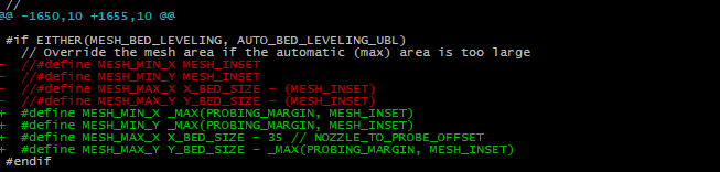
with bltouch on the left (normal carth. 3D printer, like the Ender 3) : 35mm between the probe and the nozzle
 tpruvot
on 26 Jul 2020
tpruvot
on 26 Jul 2020
If you can make a PR with a "correct", "complete" and "understandable" description, in less than about "30 lines", it will be merged for sure.
Why shouldn't there be a description for each major use case instead of always trying to get every use case in one description ? There is no memory space problem with Comments I assume ? ;)
thierryzoller
on 26 Jul 2020
* Add text that this requires 500&502 to work
Do you really want to add this comment to about every second option?
The EEPROM option has clearly only one purpose: "Remember my settings over resets and if possible over recompilations." If that should need a further explanation this should be done only near the EEPROM define - not everywhere else. (But even if that text would be blinking red and would cause an audible alarm when displayed on screen and would have to be confirmed to be read - Users will mess that up until they made their own experience)
AnHardt
on 26 Jul 2020
The
EEPROMoption has clearly only one purpose:
It is so clear that I am going to document my initial reaction: "What "EEPROM" option is he talking about ? ;)
thierryzoller
on 26 Jul 2020
* Add text that this requires 500&502 to workDo you really want to add this comment to about every second option?
TheEEPROMoption has clearly only one purpose: "Remember my settings over resets and if possible over recompilations." If that should need a further explanation this should be done only near theEEPROMdefine - not everywhere else. (But even if that text would be blinking red and would cause an audible alarm when displayed on screen and would have to be confirmed to be read - Users will mess that up until they made their own experience)
Your reaction and reply to this is demonstrating pretty nicely why RepRap/Duett have the better way to handle firmware configuration.
thierryzoller
on 26 Jul 2020
ive doubts the z probes and mounts are "standard"
tpruvot
on 26 Jul 2020
That alone is not allowed.
@AnHardt really sure? what if I reverse only X stepper counter direction? Z will not be affected by this.
But I agree with you that gcode, and more in general all machines, should follow industrial machine specifications about axes orientation.
Remove the 0,0 on the bottom left (Or replace with BED ORIGIN)
'O' means origin, but ok, bed is not specified
Add text that this requires 500&502 to work
I agree with @AnHardt and remember that if you want to properly configure your machine you need to understand what you are handling. Not knowing that your board has an EEPROM, not knowing what the eeprom purpose is, that's a problem.
What about when you will face bed leveling, jerk & linear advance calibration and hundred more configuration options?
And please remember, Marlin is an "big" piece of software, highly configurable, you may find spread on web videos and tutorials, it's really difficult to put in a simple "text" configuration file all the possible details of every single configuration option...
GMagician
on 26 Jul 2020
I will no longer engage on discussions that make the User the Problem. Not sure you realized but 3D Printing became mainstream. If you think obscuring configuration or shaming users into "you need to know what you're doing" is justifying unclear/misleading documentation you are wrong. Getting slightly upset by this type of argumentation so don't expect me to respond any further. I cannot create a PULL request for this if someone wants to assist and helping to make marlin better easier for novices and advanced users - you can help now..
thierryzoller
on 26 Jul 2020
'O' means origin, but ok, bed is not specified
What does that even mean? Are you claiming the (0,0) is representing two O's which represent Origin. Guys the effort you spend on lecturing me how stupid of a novice I am would have better be spend on creating a pull request making it easier, or work together on wording..
thierryzoller
on 26 Jul 2020
You cant understand it so, you think it should be changed... there is only so much you can do with ASCII art...
And only so much that can be done to educate new users...
This is not the place for this discussion.
ellensp
on 26 Jul 2020
This Issue Queue is for Marlin bug reports and development-related issues, and we prefer not to handle user-support questions here. (As noted on this page.) For best results getting help with configuration and troubleshooting, please use the following resources:
- MarlinFW.org Marlin Documentation
- RepRap.org Marlin Forum
- Tom's 3D Forums
- Facebook Group "Marlin Firmware"
- Facebook Group "Marlin Firmware for 3D Printers"
- Marlin Configuration on YouTube
- Marlin Discord server. Join link: https://discord.gg/n5NJ59y
After seeking help from the community, if the consensus points to a bug in Marlin, then you should post a bug report.
ellensp
on 26 Jul 2020
What does that even mean? Are you claiming the (0,0) is representing two O's w
No I'm saying that the O letter you find on bootm left, the P letter and the N are respectivelly: Origin, Probe and Nozzle
would have better be spend on creating a pull request making it easier
this is an open source software, what is not done by some people may be done by others, no one is at service of no other. Feel free to put yourself a PR that may be clear to you and help others with your same problem. This is the opportunity that a free and open source project gives
GMagician
on 26 Jul 2020
That alone is not allowed.
@AnHardt really sure?
What comes first to my mind is the cross-product used in linear-bed-leveling; that would point into the opposite direction. I'm not sure there is more, but i think so.
Ahh - yes - you would print mirrored parts, because the slicers (at least by default) also assume a right handed coordinate system.
AnHardt
on 26 Jul 2020
 /**
 * EEPROM
 *
 * Persistent storage to preserve configurable settings across reboots.
 *
 *   M500 - Store settings to EEPROM.
 *   M501 - Read settings from EEPROM. (i.e., Throw away unsaved changes)
 *   M502 - Revert settings to "factory" defaults. (Follow with M500 to init the EEPROM.)
 */
#define EEPROM_SETTINGS     // Persistent storage with M500 and M501
Somewhere here.
Even if this really now should read PERSISTEN_STORRAGE_ . Using an real EEPROM is now more the exception than the norm.
The problem with loooong descriptions is not the space they use, but the fact they are mostly skipped by the users after line ~3.
AnHardt
on 26 Jul 2020
It is not an example, it is part of a configuration manual.
It's clearly marked as an example.
/**
 * Z Probe to nozzle (X,Y) offset, relative to (0, 0).
 *
 * In the following example ...
This issue has been automatically locked since there has not been any recent activity after it was closed. Please open a new issue for related bugs.
![github-actions[bot] picture](https://avatars2.githubusercontent.com/in/15368?v=4&s=40) github-actions[bot]
on 26 Sep 2020
github-actions[bot]
on 26 Sep 2020
Related issues
 pubalan12
·
4Comments
pubalan12
·
4Comments
 Bobsta6
·
3Comments
Bobsta6
·
3Comments
 jerryerry
·
4Comments
jerryerry
·
4Comments
 esenapaj
·
3Comments
esenapaj
·
3Comments
 W8KDB
·
4Comments
W8KDB
·
4Comments