Marlin: [BUG?] G29 J: The tilting mesh's third probe location is not centered
Bug Description
When using the G29 J command on an Unified Bed Leveling enabled printer, the 3-point tilting mesh probing is invoked.
The procedure clearly takes into account the NOZZLE_TO_PROBE_OFFSET which is fine.
But the last point's x coordinate seems to be calculated from the actual probe x-offset value instead of the minimum (leftmost) mesh x-coordinate (10mm in my case, as the bed topography reports)
My Configurations
Required:
config_files.zip
Steps to Reproduce
- Home your machine with G28
- Send G29 J V4 command to get the 3-point probing coordinates
Expected behavior: [What you expect to happen]
On my previous firmware (bugfix 2.0.x September 6th 2019 compilation) the third point's x-coordinate was roughly in the center of my bed. I expect this last point to be in the middle of the minimum and maximum x-coordinates of the mesh.
Actual behavior: [What actually happens]
The third tilting mesh point's x-coordinate is way too much displaced to the left because it's using the probe's offset value to calculate the final point coordinates.
Additional Information
My current firmware is bugfix 2.0.x Marlin March 17th 2020 compilation.
My Z-Probe Offsets are: M851 X47.00 Y-13.00
My mesh bounds set as MESH_INSET 10
All 36 points of my bed leveling mesh are filled in although only 5x5 where actually probed, the rest where retrieved with G29 P2.
These are my 3 point locations after performing a G29 J V4 command:
Tilting mesh (1/3)
Bed X: 47.000 Y: 10.000 Z: -0.040
Corrected_Z=0.06
Tilting mesh (2/3)
Bed X: 225.000 Y: 10.000 Z: -0.107
Corrected_Z=0.10
Tilting mesh (3/3)
Bed X: 89.000 Y: 209.000 Z: 0.090
Corrected_Z=0.06
So this 3rd point location's x coordinate (89.0mm) is clearly a result of (225-47)/2 instead of (225-10)/2 which results in a last probe being too much to the left, in my case.
Is this a bug that makes the normal bed plane calculation wrong, or it's just an "aesthetic thing"?
Thanks
 zalexzperez
All 26 comments
I too have this.
- bugfix 2.0.x Marlin March 19th 2020.
- X_BED_SIZE 232
- Y_BED_SIZE 230
- NOZZLE_TO_PROBE_OFFSET { -42.86, -6.07, -1.65 }
- MESH_INSET 15
- All 121 mesh points was probed and filled by BLTouch
My 3 point location after G29 J V4:
Tilting mesh (1/3)
Bed X: 15.000 Y: 15.000 Z: 0.215
Corrected_Z=0.06
Tilting mesh (2/3)
Bed X: 217.000 Y: 15.000 Z: 0.394
Corrected_Z=0.16
Tilting mesh (3/3)
Bed X: 101.000 Y: 215.000 Z: 0.090
Corrected_Z=0.00
The 3rd points X coordinate should be X: 158.86, (232/2-(-42.86)), in order to the probe to be at X: 116 (232/2)
Actual position: X: 101 (232/2-15)
 qwewer0
on 19 Mar 2020
qwewer0
on 19 Mar 2020
I too have this.
- bugfix 2.0.x Marlin March 19th 2020.
- X_BED_SIZE 232
- Y_BED_SIZE 230
- NOZZLE_TO_PROBE_OFFSET { -42.86, -6.07, -1.65 }
- MESH_INSET 15
- All 121 mesh points was probed and filled by BLTouch
My 3 point location after G29 J V4:
Tilting mesh (1/3)
Bed X: 15.000 Y: 15.000 Z: 0.215
Corrected_Z=0.06
Tilting mesh (2/3)
Bed X: 217.000 Y: 15.000 Z: 0.394
Corrected_Z=0.16
Tilting mesh (3/3)
Bed X: 101.000 Y: 215.000 Z: 0.090
Corrected_Z=0.00The 3rd points X coordinate should be X: 158.86, (232/2-(-42.86)), in order to the probe to be at X: 116 (232/2)
Actual position: X: 101 (232/2-15)
All points filled by the probe? But...how can your machine reach a probe location of X=232mm when it's 42.86mm to the left of your nozzle? Can your nozzle reach an X coordinate of 274.86mm? (232+42.86). Edit: I guess in your firmware, those coordinates are nozzle coordinates, not the actual probe ones.
And no, you don't seem to have the same problem. Your first point is at x=15 (0+15) and your second point is at x=217 (232-15), so the third point is at the proper x=(217-15)/2. It's in the center of the two ends of your mesh (not the center of your bed, it isn't supposed to be in the center of your bed as far as I know). In conclusion, you're getting the same results as I had in my previous firmware.
My third point is NOT in the center of the two ends of my mesh (Xmin=10, Xmax=225) but rather in the result of evaluating (47, 225).
zalexzperez
on 19 Mar 2020
All points filled by the probe?
The probe can fill all the points, because I modified the printer, so X_MAX_POS (X_BED_SIZE + 30)
But...how can your machine reach a probe location of X=232mm
It can't, but it doesn't need to, as the max X coordinate for probing is X=217, so the nozzle only needs to reach X=259.86
And no, you don't seem to have the same problem.
I might not have the same problem, but it is still a problem that the last tilting measurement isn't takes place at the middle of the bed/mesh, as far as the X coordinate.
so the third point is at the proper x=(217-15)/2. It's in the center of the two ends of your mesh (not the center of your bed
My mesh is centered on the bed, with 15mm inset from the edges of the bed, so the third probing point should be at the center of the bed/mesh (X) too.
qwewer0
on 19 Mar 2020
All points filled by the probe?
The probe can fill all the points, because I modified the printer, so X_MAX_POS (X_BED_SIZE + 30)
But...how can your machine reach a probe location of X=232mm
It can't, but it doesn't need to, as the max X coordinate for probing is X=217, so the nozzle only needs to reach X=259.86
And no, you don't seem to have the same problem.
I might not have the same problem, but it is still a problem that the last tilting measurement isn't takes place at the middle of the bed/mesh, as far as the X coordinate.
so the third point is at the proper x=(217-15)/2. It's in the center of the two ends of your mesh (not the center of your bed
My mesh is centered on the bed, with 15mm inset from the edges of the bed, so the third probing point should be at the center of the bed/mesh (X) too.
I'm not an expert, but I think in order to calculate a proper normal plane for the leveling system to do its job, the third point needs to be in mathematical center of your mesh, not the geometric center of your bed, and that is found between 15 and 217 (x=101). But it's just an assumption.
In any case, we're getting different results, and that's why I opened this issue.
I hope someone shed light on this topic.
zalexzperez
on 19 Mar 2020
I'm not an expert, but I think in order to calculate a proper normal plane for the leveling system to do its job, the third point needs to be in mathematical center of your mesh, not the geometric center of your bed, and that is found between 15 and 217 (x=101).
Yes the X coordinate - for me - should be between 15 and 217, but the left side of the mesh is not at X=0, but rather at X=15, so the center point should be 232/2 (or with your analogy (217-15)/2+15)
qwewer0
on 19 Mar 2020
I'm not an expert, but I think in order to calculate a proper normal plane for the leveling system to do its job, the third point needs to be in mathematical center of your mesh, not the geometric center of your bed, and that is found between 15 and 217 (x=101).
Yes the X coordinate - for me - should be between 15 and 217, but the left side of the mesh is not at X=0, but rather at X=15, so the center point should be 232/2 (or with your analogy (217-15)/2+15)
Yes, there's an offset but I'm sure it's accounted for (I had it like that for many months in my previous firmware)
Not so sure about my case, though.
zalexzperez
on 19 Mar 2020
We need a Marlin genius here...
qwewer0
on 19 Mar 2020
I think in order to calculate a proper normal plane for the leveling system to do its job, the third point needs to be in mathematical center of your mesh
Calculating a plane requires three points. It doesn’t matter where they are, as long as they are not in a straight line.
That said, it does sound like there could be an issue, I would have expected the X of the third point to be centered between the first two X values.
 sjasonsmith
on 19 Mar 2020
sjasonsmith
on 19 Mar 2020
Been printing some big stuff.
The extrusion width varies like crazy (you could say like from 0.2 to 0.5mm when set to 0.4) in a few centimeters' distance. Temporarily disabled bed leveling and the extrusion was consistent, so I probably had the most accurate mesh.
EDIT:
Just reflashed the old firmware, and now my probing coordinates are:
Tilting mesh (1/3)
Bed X: 47.000 Y: 10.000 Z: -0.035
Tilting mesh (2/3)
Bed X: 224.000 Y: 10.000 Z: 0.012
Tilting mesh (3/3)
Bed X: 117.000 Y: 209.000 Z: -0.075
So the X coordinate for the 3rd point is not between 10 and 224, but it's actually between 0 and 234 (bed size)
zalexzperez
on 22 Mar 2020
@zalexzperez is issue gone?
 boelle
on 20 Jun 2020
boelle
on 20 Jun 2020
@boelle No, it is still of by -10 in X, 149 instead of 159. (In my case) Tested on the latest bugfix.
qwewer0
on 21 Jun 2020
Checking
https://github.com/MarlinFirmware/Marlin/blob/bugfix-2.0.x/Marlin/src/module/probe.h#L193
it seems the calculation for the three probe locations is like this:
      static inline void get_three_points(T points[3]) {
        #if HAS_FIXED_3POINT
<cut>
        #else
          #if IS_KINEMATIC
<cut>
          #else
            points[0].set(min_x(), min_y());
            points[1].set(max_x(), min_y());
            points[2].set((max_x() - min_x()) / 2, max_y());
          #endif
        #endif
      }
from your config and your post I understood you use the following settings:
My Z-Probe Offsets are: M851 X47.00 Y-13.00
My mesh bounds set as MESH_INSET 10
Configuration.h
// The size of the print bed
#define X_BED_SIZE 235
#define Y_BED_SIZE 222 //Changed from 232 to 222 (Direct drive mount)
Configuration.h
// Travel limits (mm) after homing, corresponding to endstop positions.
#define X_MIN_POS 0
#define Y_MIN_POS -17 //Changed for direct drive mount
#define Z_MIN_POS 0
#define X_MAX_POS X_BED_SIZE
#define Y_MAX_POS Y_BED_SIZE
Configuration.h
#define NOZZLE_TO_PROBE_OFFSET { 47, -13, 0 } //Changed

// Most probes should stay away from the edges of the bed, but
// with NOZZLE_AS_PROBE this can be negative for a wider probing area.
#define MIN_PROBE_EDGE 10
btw, #define MIN_PROBE_EDGE 10should give you an error due to the following sanity check:
SanityCheck.h
#elif defined(MIN_PROBE_EDGE)
  298:   #error "MIN_PROBE_EDGE is now called PROBING_MARGIN. Please update your configuration."
anyway, give all this, the code seems to calculate the locations like this:
Conditionals_post.h:
// Define center values for future use
#define _X_HALF_BED ((X_BED_SIZE) / 2)
#define _Y_HALF_BED ((Y_BED_SIZE) / 2)
#define X_CENTER TERN(BED_CENTER_AT_0_0, 0, _X_HALF_BED)
#define Y_CENTER TERN(BED_CENTER_AT_0_0, 0, _Y_HALF_BED)

// Get the linear boundaries of the bed
#define X_MIN_BED (X_CENTER - _X_HALF_BED)
#define X_MAX_BED (X_MIN_BED + X_BED_SIZE)
#define Y_MIN_BED (Y_CENTER - _Y_HALF_BED)
#define Y_MAX_BED (Y_MIN_BED + Y_BED_SIZE)
probe.h
min_x():
_MAX((X_MIN_BED) + (PROBING_MARGIN_LEFT), (X_MIN_POS) + offset_xy.x)
_MAX( (0 + 10), (0 + 47) ) -> min_x() will return 47
probe.h
max_x():
_MIN((X_MAX_BED) - (PROBING_MARGIN_RIGHT), (X_MAX_POS) + offset_xy.x)
_MIN( (235 - 10), (235 + 47) ) -> max_x() will return 225
probe.h
min_y():
_MAX((Y_MIN_BED) + (PROBING_MARGIN_FRONT), (Y_MIN_POS) + offset_xy.y)
_MAX( (0 + 10), (-17 + -13) ) -> min_y() will return 10
probe.h
max_y():
_MIN((Y_MAX_BED) - (PROBING_MARGIN_BACK), (Y_MAX_POS) + offset_xy.y)
_MIN( (222 - 10), (222 + -13) ) -> max_y() will return 209
finally, the calculation of the probe locations (in probe.h) will be like the following:
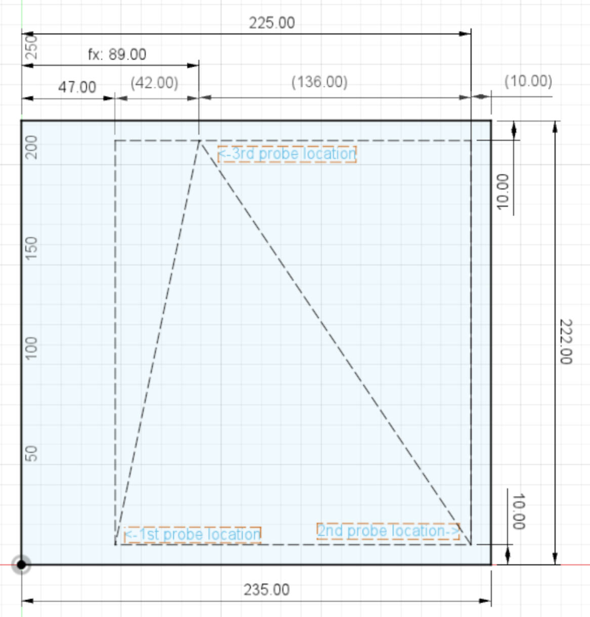
probe.h
points[0].set(min_x(), min_y());
points[0].set( 47, 10 );

points[1].set(max_x(), min_y());
points[1].set( 225, 10 );

points[2].set((max_x() - min_x()) / 2, max_y());
points[2].set( (225 - 47) /2, 209 );
points[2].set( 178/2, 209 );
points[2].set( 89, 209 );
This is the same as reported in the first post:
Tilting mesh (1/3)
Bed X: 47.000 Y: 10.000 Z: -0.040
Corrected_Z=0.06
Tilting mesh (2/3)
Bed X: 225.000 Y: 10.000 Z: -0.107
Corrected_Z=0.10
Tilting mesh (3/3)
Bed X: 89.000 Y: 209.000 Z: 0.090
Corrected_Z=0.06
This confirms (IMHO):
So this 3rd point location's x coordinate (89.0mm) is clearly a result of (225-47)/2 instead of (225-10)/2
The offset for the probe is:
My Z-Probe Offsets are: M851 X47.00 Y-13.00
So its relative position to the nozzle is front (Y-13), right (X47).
max_x() is not constrained by the probe-offset as the probe would be able to reach X_MAX_POS; max_x() seems (IMHO) be correctly return 225.
min_x() returns 47 because as it is constrained by the probe-offset (X47), as the probe would not be able to reach X_MIN_POS; max_x() seems (IMHO) be correctly return 47.
Due to the probe-offset, the mesh is actually not being centered on the bed and therefor the 3rd-probing-location should be shifted in X direction according to the probe-offset to being centered to the mesh in X direction. So perhaps the correct calculation for the 3rd location should be
points[2].set((min_x() + max_x()) / 2, max_y());
points[2].set( (47 + 225) /2, 209 );
points[2].set( 272/2, 209 );
points[2].set( 136, 209 );
Could someone please double check and verify this?
 MoellerDi
on 21 Jun 2020
MoellerDi
on 21 Jun 2020
I did some further calculation and it seems the location for the 3rd probe should (IMHO) actually be points[2].set( 136, 209 );
X136 - 89 = 47 (actually X_MIN_POS 0 + probe-offset X 47)
X136 + 89 = 225 (actually X_MAX_POS - PROBING_MARGIN_RIGHT)
This means the mesh size X is 2*89=178
mesh size X (178) + probe-offset X (47) = 225 (X_MAX_POS - PROBING_MARGIN_RIGHT)
MoellerDi
on 21 Jun 2020
3-point leveling works if:
- the probed positions are known
- the points are not kollinear (on one line)
It works best if the points are as far apart from each other as possible.
If the third point is in the middle or not makes no difference.
 AnHardt
on 21 Jun 2020
AnHardt
on 21 Jun 2020
That's pretty clear and I'm not saying otherwise (at least I hope so because I'm not a native English speaker) ;-)
Anyway, this issue is (as I understood) about "the tilting mesh's third probe location is not centered" I was just trying to understand how the code works. While I was on it I found the location of the 3rd probing point is currently not centered on X to the bed nor is it centered on X to the mesh.
The code is not having much documentation/comments but reading the code, it seems one was trying to put the 3rd probing location on X in the middle of something (points[2].set((max_x() - min_x()) / 2, max_y());). But as outlined in my post above, it's not relative to the bed nor to the mesh and therefor it could be confusing and one might raise an issue like this.
PR #17964 just tweaked the calculation for the very last center move in a very similar way. That PR got merged a few days ago. That's why I assume the 3rd probe location should be centered on X to the mesh. Especially because the calculation of the 1st and 2nd probe location seems to be based on the probe offset and probing margin.
As pointed out by @AnHardt:
It works best if the points are as far apart from each other as possible.
Having the 3rd probe location centered on X to the mesh makes it as far away from 1st and 2nd probe location as possible. Any other location will bring it (IMHO) closer to either the 1st or the 2nd probe location.
MoellerDi
on 21 Jun 2020
@MoellerDi it looks like you are correct. I could understand arguments for centering in the bed and centering in the mesh, and the current implementation does neither. Centering in the mesh is probably the correct solution.
That said, it is probably not hurting leveling performance significantly right now, since the selected points still form a valid plane. That makes it a lower priority to fix, even though the fix is simple. You or any of the others contributing to this discussion would be more than welcome to submit a fix as a Pull Request.
sjasonsmith
on 21 Jun 2020
Having the 3rd probe location centered on X to the mesh makes it as far away from 1st and 2nd probe location as possible. Any other location will bring it (IMHO) closer to either the 1st or the 2nd probe location.
No.
What matters is the differences in x and y. These are the same.
Let's imagine a rectangle A,B,C,D. The first probing points are in A and B. Then the height of the triangle is the same when point 3 is anywhere on the line between C and D.
From the 3 points we are building 2 difference vectors. From them we calculate the cross-product and get the vector perpendicular to the surface. That's normalized to length one. Now we can easily solve for the z component on the plane for any combination of x and y.
The 'size' of the triangle matters only because we have a limited resolution in x,y and z. (not better than one step). So by maximizing the the numbers of the differences we are minimizing the relative error.
AnHardt
on 22 Jun 2020
Don't get me wrong, I'm not saying the location of the 3rd probe location will or might have any impact on the UBL. I was just saying that the way the 3rd probe location is currently calculated seems be somewhat confusion as it's not centered to the bed nor to the mesh.
Below is what the current code is calculating:
And this is what I'm tying to implement in PR #18383:
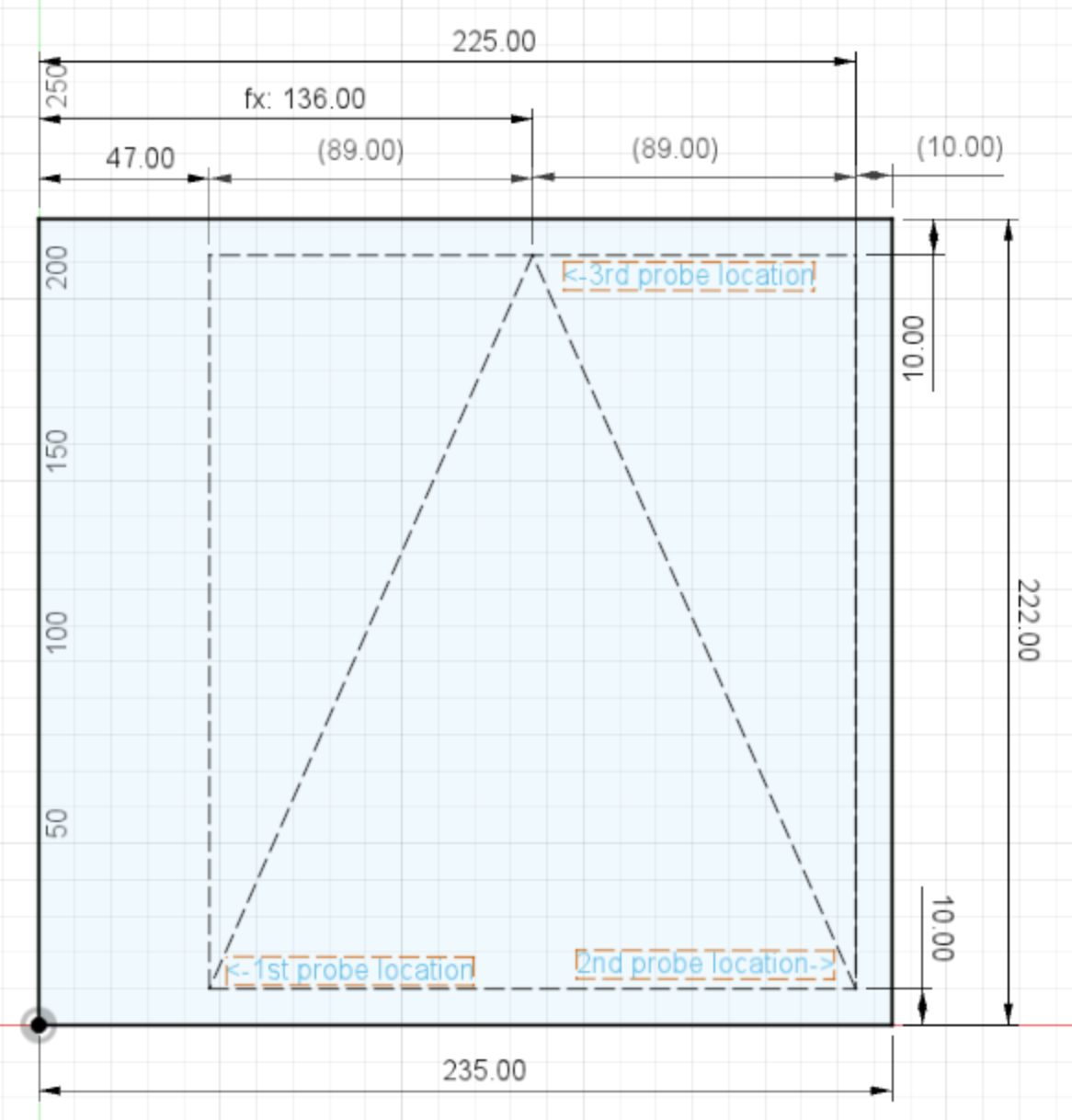
IMHO all 3 probe location seems be placed more logically with the new calculation.
And if the location of the 3rd probe point won't matter, why not implementing it in a way a user would expect it?
MoellerDi
on 22 Jun 2020
And all what i'm saying is: i don't care - it does not matter - it's a purely cosmetic problem.
The question more interesting to me is: Can this be speed-optimized? Does it make sense to search for a faster point distribution when either x or y is able to move faster then the other. Maybe depending on where we are before the probing begins?
AnHardt
on 22 Jun 2020
@MoellerDi i think your change is good because it will prevent others from spending time questioning whether something is wrong.
sjasonsmith
on 22 Jun 2020
can we close this one since PR was merged?
boelle
on 29 Jun 2020
@zalexzperez & @MoellerDi, I am presuming this is fixed since there hasn't been any comment in 5 days since the fix went in.
I am going to flag this issue as stale. I know it isn't _really_ stale, but that will allow a bot to come through and auto-close it if nobody has replied in a few days.
sjasonsmith
on 30 Jun 2020
@sjasonsmith sorry for the slow reply. I was busy with other stuff. IMHO the PR should have fixed it but I have not seen any feedback from @zalexzperez so far. Is there anything else to be done from my end?
MoellerDi
on 7 Jul 2020
@MoellerDi you are right, we have not seen anything from @zalexzperez since 22 March,
since you are the most active one we will take your word for that its fixed, if @zalexzperez does not agree he can speak up and say why
should we close this one as fixed and reopen if @zalexzperez says otherwise?
boelle
on 7 Jul 2020
Yes.
sjasonsmith
on 7 Jul 2020
This issue has been automatically locked since there has not been any recent activity after it was closed. Please open a new issue for related bugs.
![github-actions[bot] picture](https://avatars2.githubusercontent.com/in/15368?v=4&s=40) github-actions[bot]
on 6 Sep 2020
github-actions[bot]
on 6 Sep 2020
Related issues
 ahsnuet09
·
3Comments
ahsnuet09
·
3Comments
 Kaibob2
·
4Comments
Kaibob2
·
4Comments
 ceturan
·
4Comments
ceturan
·
4Comments
 Anion-anion
·
3Comments
Anion-anion
·
3Comments
 manianac
·
4Comments
manianac
·
4Comments
Most helpful comment
@MoellerDi i think your change is good because it will prevent others from spending time questioning whether something is wrong.