Marlin: [BUG] Bulge on linear advance speed change
Bug Description
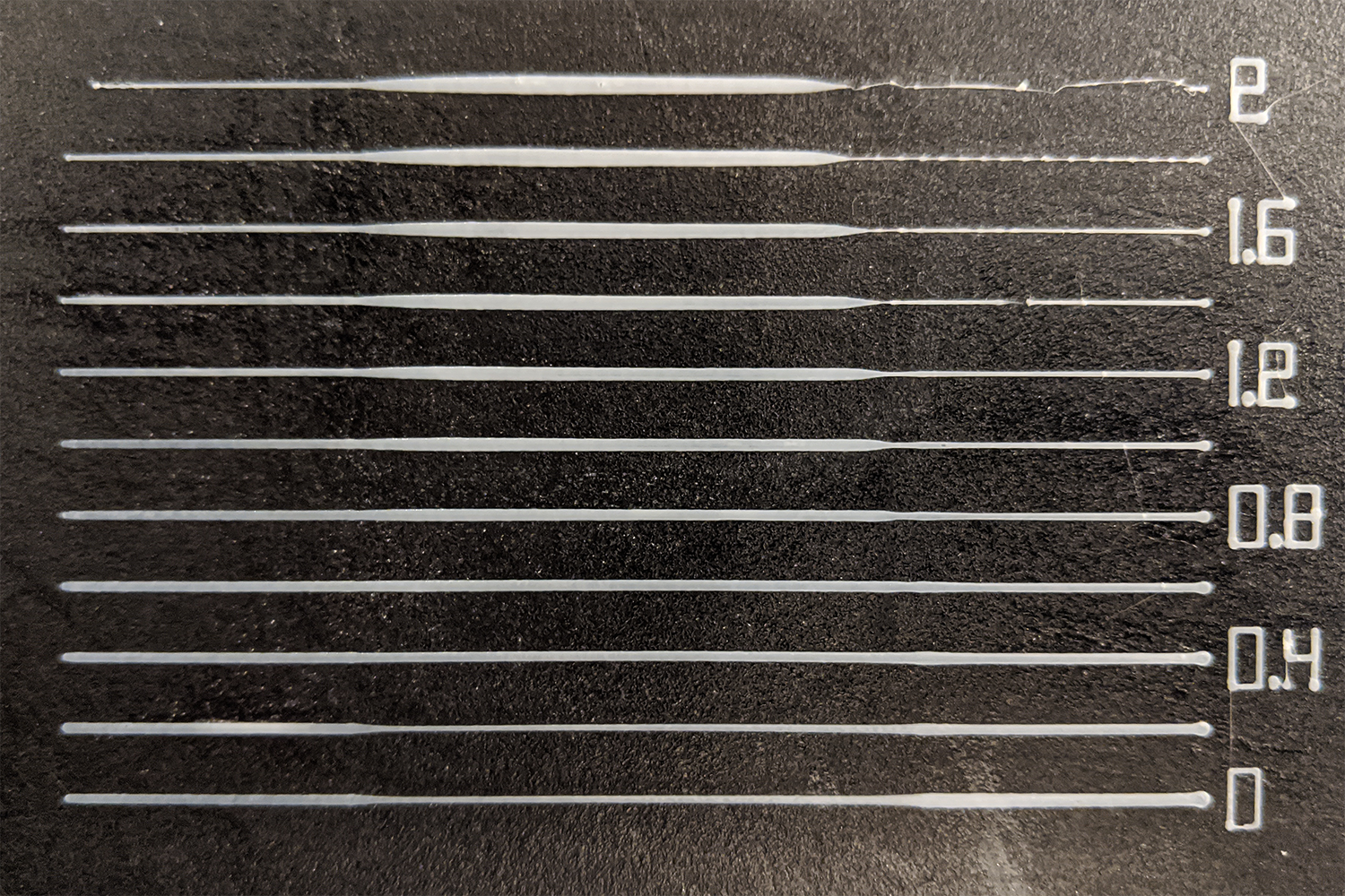
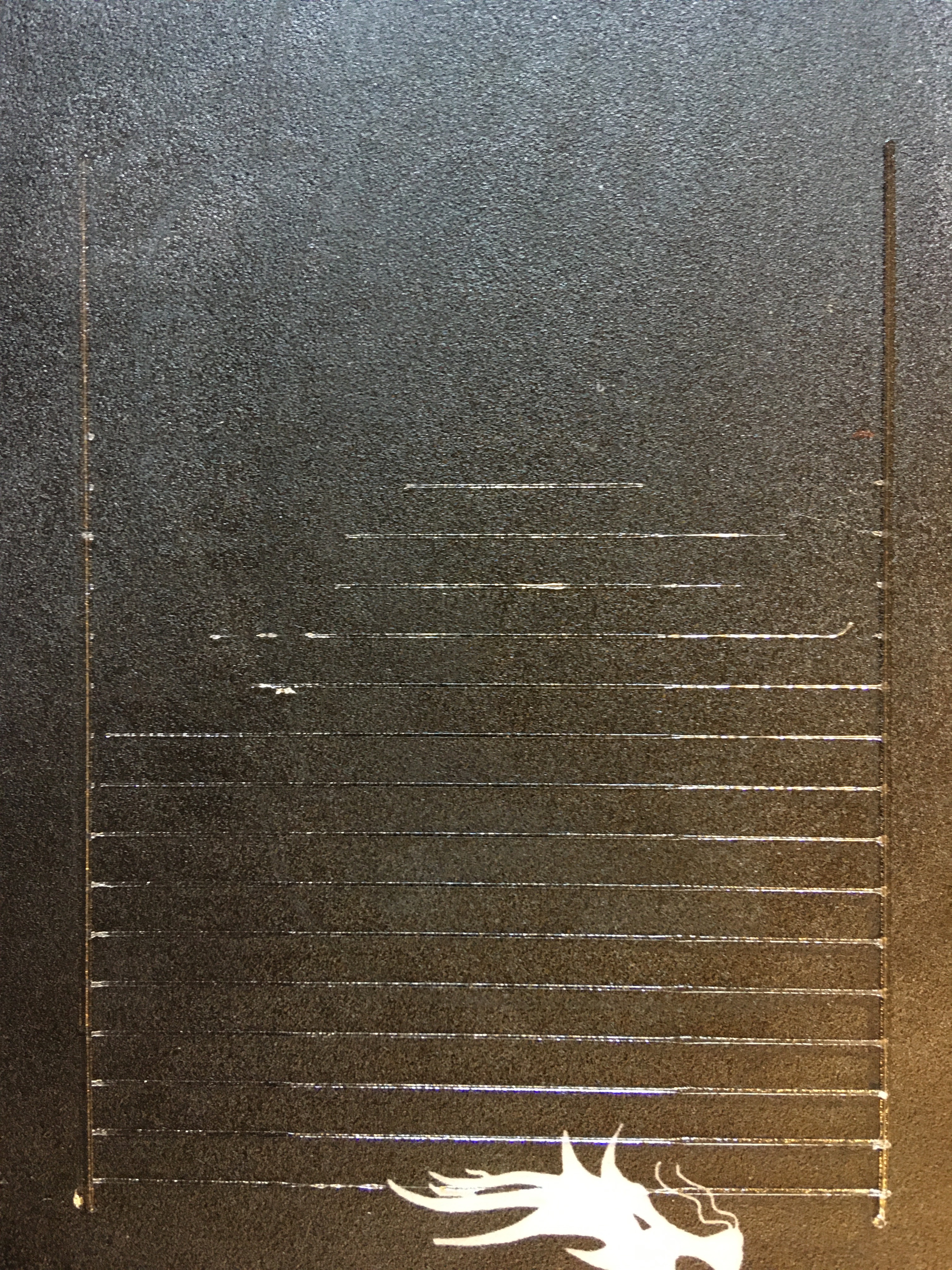
When using linear advance on my bowden system, no matter what value, even between 0 and 5, there is a big drop of plastic at the point where the speed changes, even tho the 3 segments are changed correctly (my correct k value is around 0.5)
My Configurations
Marlin.zip
(Marlin bugfix as of 21 Jan)
Cr10S, skr 1.3, TMC 2209
Scurve acceleration, Standard jerk
Expected behavior: [What you expect to happen]
Linear transition between slow and fast speed
Actual behavior: [What actually happens]
Big drop left at the speed change
 Liger0
All 169 comments
In your slicer it will help to tell it not to subdivide curves too finely. Too many small segments lead to planner starvation because the G-code input cannot feed the queue fast enough.
 thinkyhead
on 16 Feb 2020
thinkyhead
on 16 Feb 2020
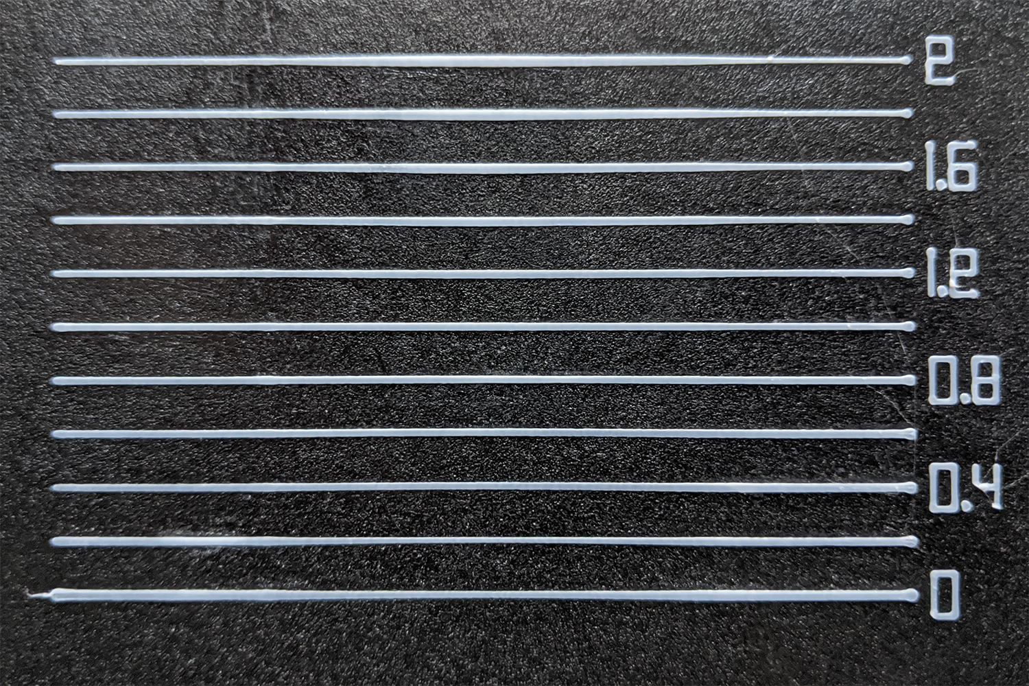
I am directly referring to the official linear advance test.
There is not even a minimal difference in the bulge between 0 and 3.
Liger0
on 17 Feb 2020
Tried with scurve off: No difference.
Liger0
on 18 Feb 2020
there is a big drop of plastic at the point where the speed changes
Tried with scurve off: No difference.
I think I have the same issue.
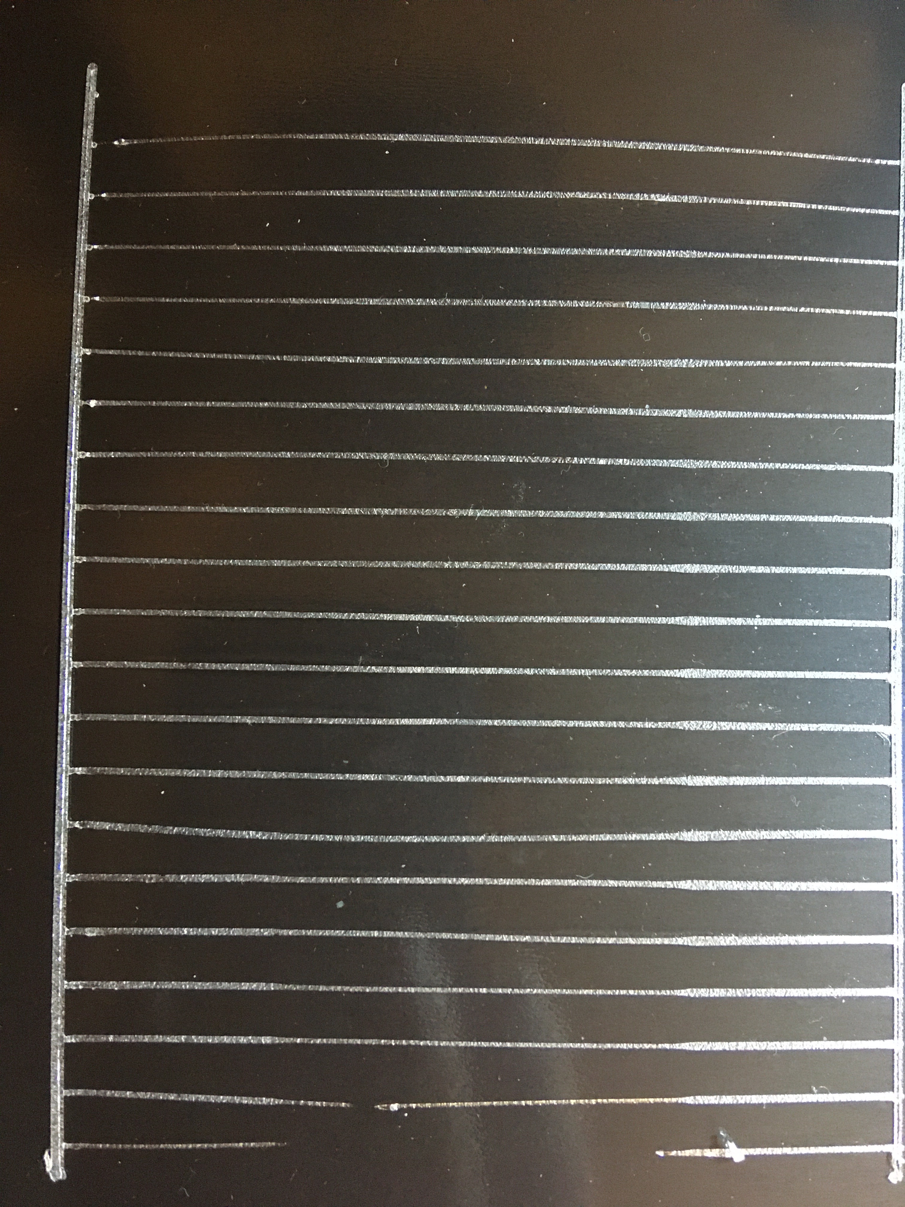
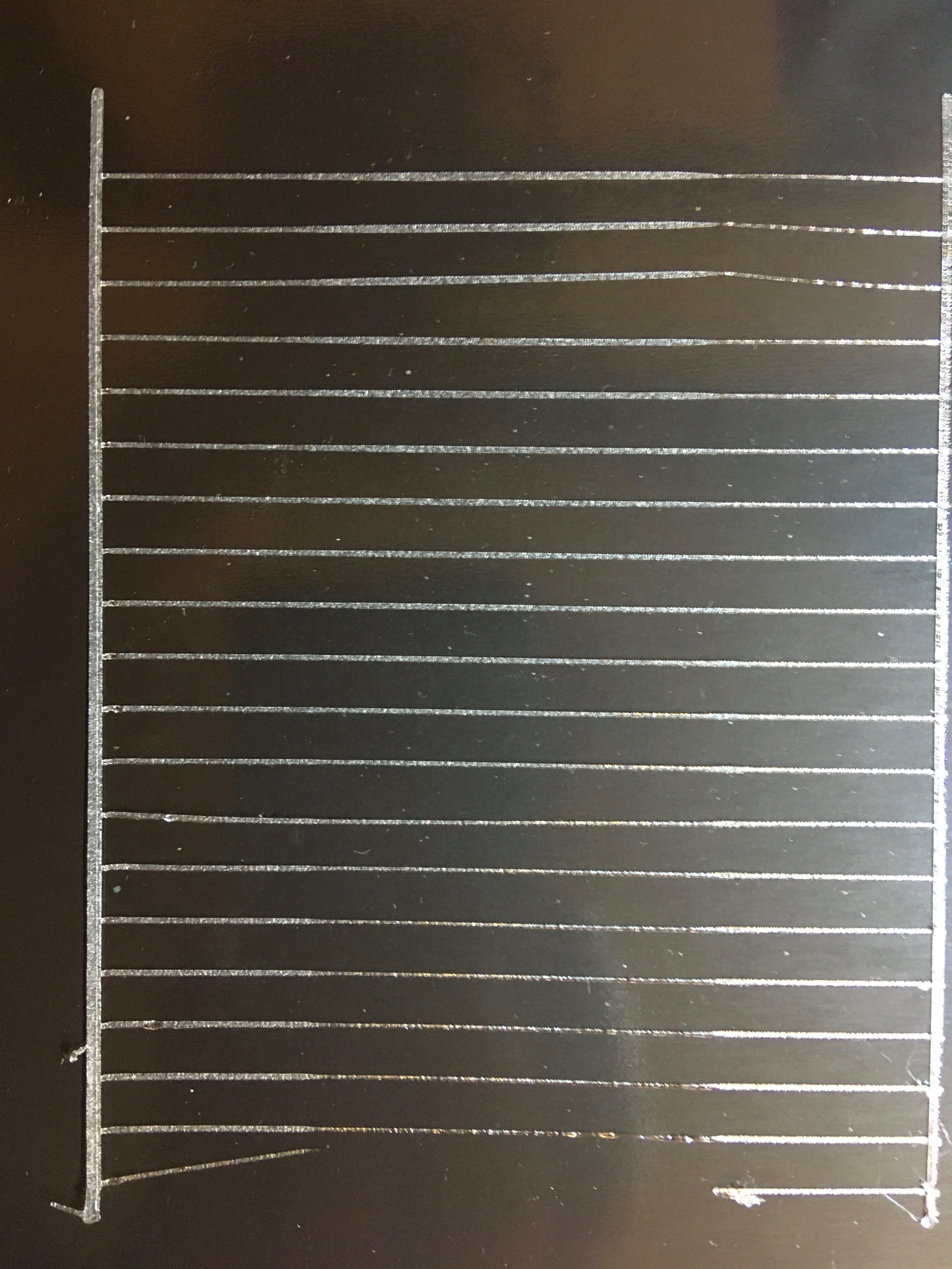
While calibrating my linear advance settings, I also noticed a bulge at the speed change.
I used the official linear advance test found here: https://marlinfw.org/tools/lin_advance/k-factor.html
While trying around I also tried very low acceleration settings and noticed something strange:
At the point where the print head is supposed to accelerate, it actually decelerates first before speeding up. This can be clearly seen and heard. I don't think this behavior is correct. Maybe you want to try it out for yourself? These are the speed settings I used:
; Settings Speed:
; Slow Printing Speed = 900 mm/min
; Fast Printing Speed = 3600 mm/min
; Movement Speed = 7200 mm/min
; Retract Speed = 2400 mm/min
; Printing Acceleration = 40 mm/s^2
 fatalbranch
on 1 Mar 2020
fatalbranch
on 1 Mar 2020
In order to track down spurious issues, after first testing the latest bugfix-2.0.x code it can help to go back in time to find a version of Marlin that doesn't exhibit the issue. Through a process of bisection you can quickly locate the day when the issue first arises. We can then examine the code changes from that time period and see which changes are the most likely problem.
thinkyhead
on 2 Mar 2020
I can confirm this also - when moving from the first slow segment into the middle fast segment on each line, it not only decelerates, it also briefly moves the extruder backward just before the normal surge forward. It's been a long time since I last tried to set up LA, so I couldn't even begin to guess when it last worked.
 VanessaE
on 9 Mar 2020
VanessaE
on 9 Mar 2020
It never worked correctly to me.
Liger0
on 9 Mar 2020
My i3 plus 3D printer which shows the strange behavior is running a Marlin firmware version 1.1.4. (You can find the the firmware project here https://github.com/Silverquark/i3PlusPlus)
If the bug was never fixed in between, this would probably mean it has been around since at least mid 2017.
fatalbranch
on 11 Mar 2020
briefly moves the extruder backward
Yeah, Linear Advance is allowed to do that.
It's been a while since @Sebastianv650 has been around, but I'm sure if LA was seriously broken he would have harshly criticized us by now!
thinkyhead
on 12 Mar 2020
briefly moves the extruder backward
Yeah, Linear Advance is allowed to do that.
Sure, if it's moving from a fast segment to a slow segment in the calibration pattern, E moving backward slightly makes perfect sense, since it has to bleed-off some pressure just before the slow segment starts. On the transitions from slow to fast on each line, one would expect only a forward E surge, to boost the pressure just before the fast segment starts.
That's how it worked when LA v1.5 was introduced (and I seem to recall that that's more or less how it worked in the old implementation that preceded it).
But now, a slow-to-fast transition is getting both a backward move and a forward surge, one after the other, which cancel each other out. Thus the start of the fast segment never fills-out. I did not take note of the behavior of fast-to-slow transitions, but I'll hazard a guess that an inverse pair of moves happens there, since the fast-to-slow bulges never smooth out.
Since @Sebastianv650 hasn't stopped by to yell at anyone, I can only assume he has moved on to some other project.
VanessaE
on 12 Mar 2020
The last I remember hearing from @Sebastianv650 was https://github.com/MarlinFirmware/Marlin/issues/10272#issuecomment-534905221 where it looked like he had moved on to other things.
 ManuelMcLure
on 12 Mar 2020
ManuelMcLure
on 12 Mar 2020
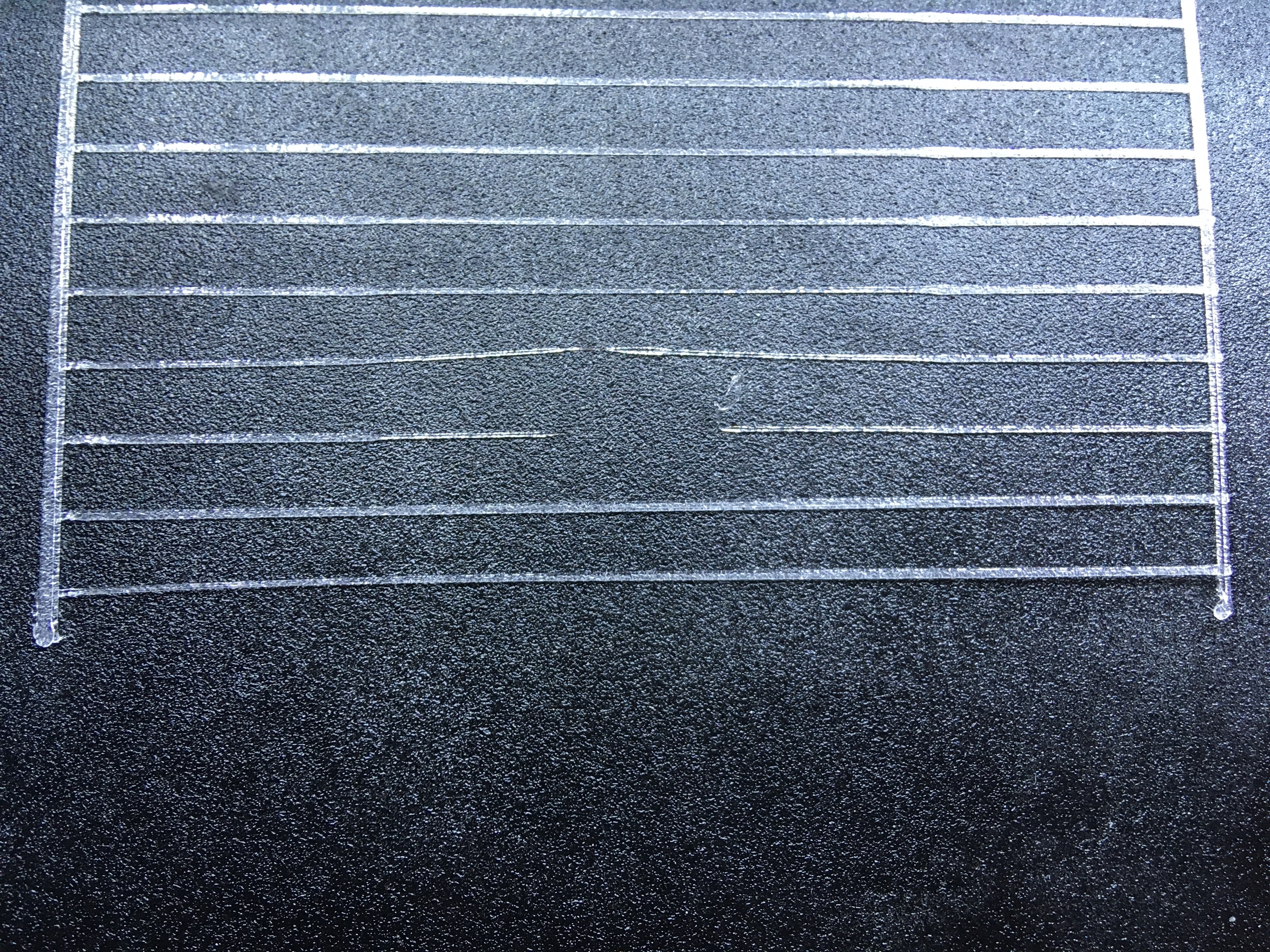
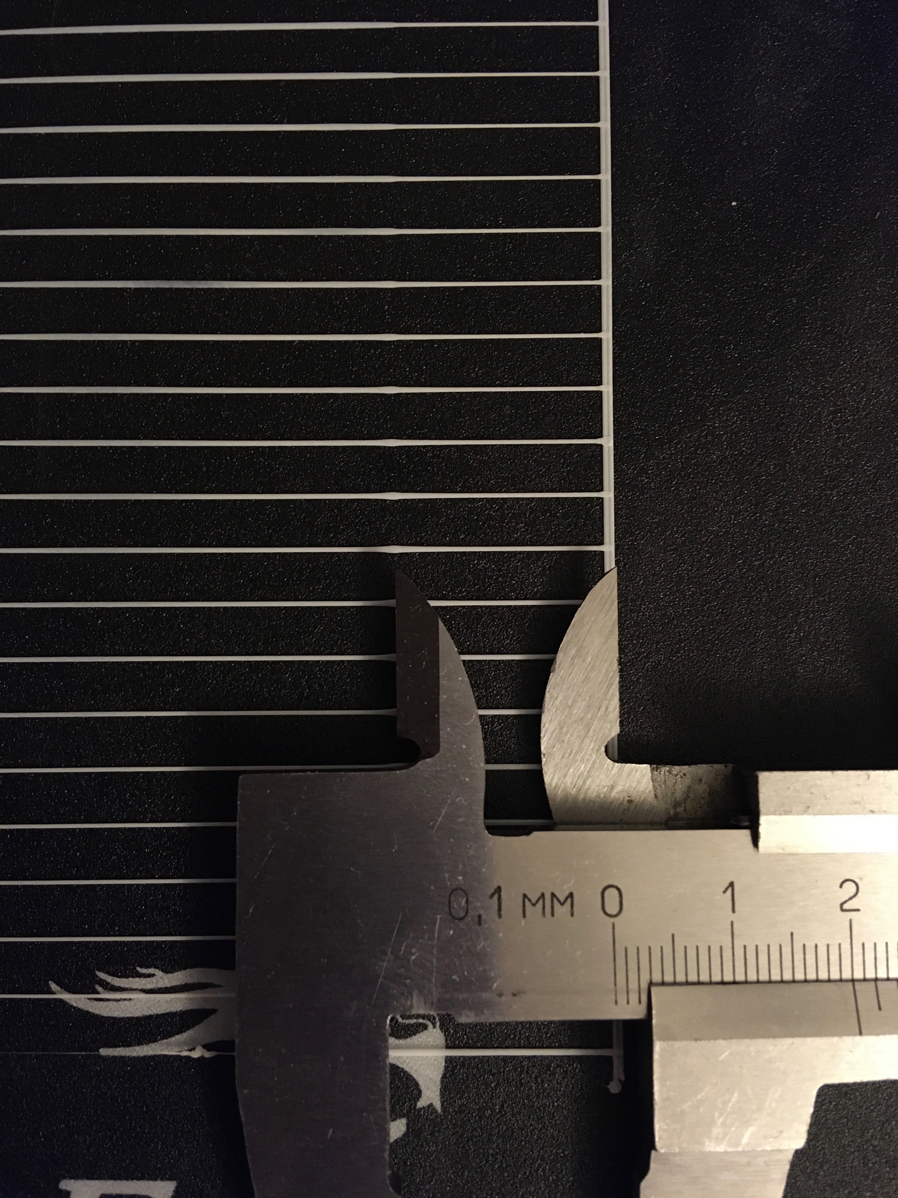
@Liger0 Can you upload a picture of the bulge? I think I have a similar problem, but I'm not sure because the description is a bit vage. This is an image ob the bulge on my pattern:

 XDA-Bam
on 14 Apr 2020
XDA-Bam
on 14 Apr 2020
Yes that's exactly like yours, just a little bigger and visible on all the lines all the way from 0 to 5.
Liger0
on 14 Apr 2020
Good. What extruder do you use? Bowden, direct drive or flexdrive? I've got the problem on a stock Ender 3 Pro, which uses a Bowden.
XDA-Bam
on 14 Apr 2020
I had this really noticeably on stock bowden Ender 3, and still can see it - even if very slightly - with direct drive now. (K=0.9, K=0.18)
 qwewer0
on 14 Apr 2020
qwewer0
on 14 Apr 2020
I use bowden.
Liger0
on 14 Apr 2020
I have this issue as well, the bulge exists all the way up to 1.8K or so. Running marlin 1.1.9 on an Ender 3.
 NoxIX
on 21 Apr 2020
NoxIX
on 21 Apr 2020
Same issue here with SKR pro 1.1, 2208s, Bowden and latest bug fix from today. It’s been an issue for a VERY long time even back to the AVR days in my past setup. This has been seen across my i3 variants with both Bowden and direct drive. I have just lived with it and assumed I was just not calibrating something properly. Which is still a likely possibility. :)
-William
 viper93458
on 21 Apr 2020
viper93458
on 21 Apr 2020
…it looked like he had moved on to other things.
I guess that means we'll have to actually understand his code now! I was hoping to maybe get him to throw us a hint in a short comment. Has anyone looked at Prusa Firmware to see if their algorithm is significantly different?
_Anyways…_
Just so everyone is on the same page here:
- S-curve acceleration is not deemed to be compatible with Linear Advance. You can experiment with it, so it's not completely blocked, but Linear Advance expects to be working alongside of Linear Acceleration. So, please test with S-Curve Acceleration disabled and compare those results.
thinkyhead
on 22 Apr 2020
S-curve acceleration is not deemed to be compatible with Linear Advance. You can experiment with it, so it's not completely blocked, but Linear Advance expects to be working alongside of Linear Acceleration. So, please test with S-Curve Acceleration disabled and compare those results.
Oh really? I've only heard it being used along with S-curve, I'll go test this rq.
NoxIX
on 22 Apr 2020
@thinkyhead
So I tested it with S-curve disabled, if there was a difference, it was marginal. There is still a bulge at the slow down transition. This, eventually goes away but then your slower speeds are much thinner, if there at all.
I tested V1 last night and found that the opposite problem exists, where the fast portion is not fed fast enough.
NoxIX
on 22 Apr 2020
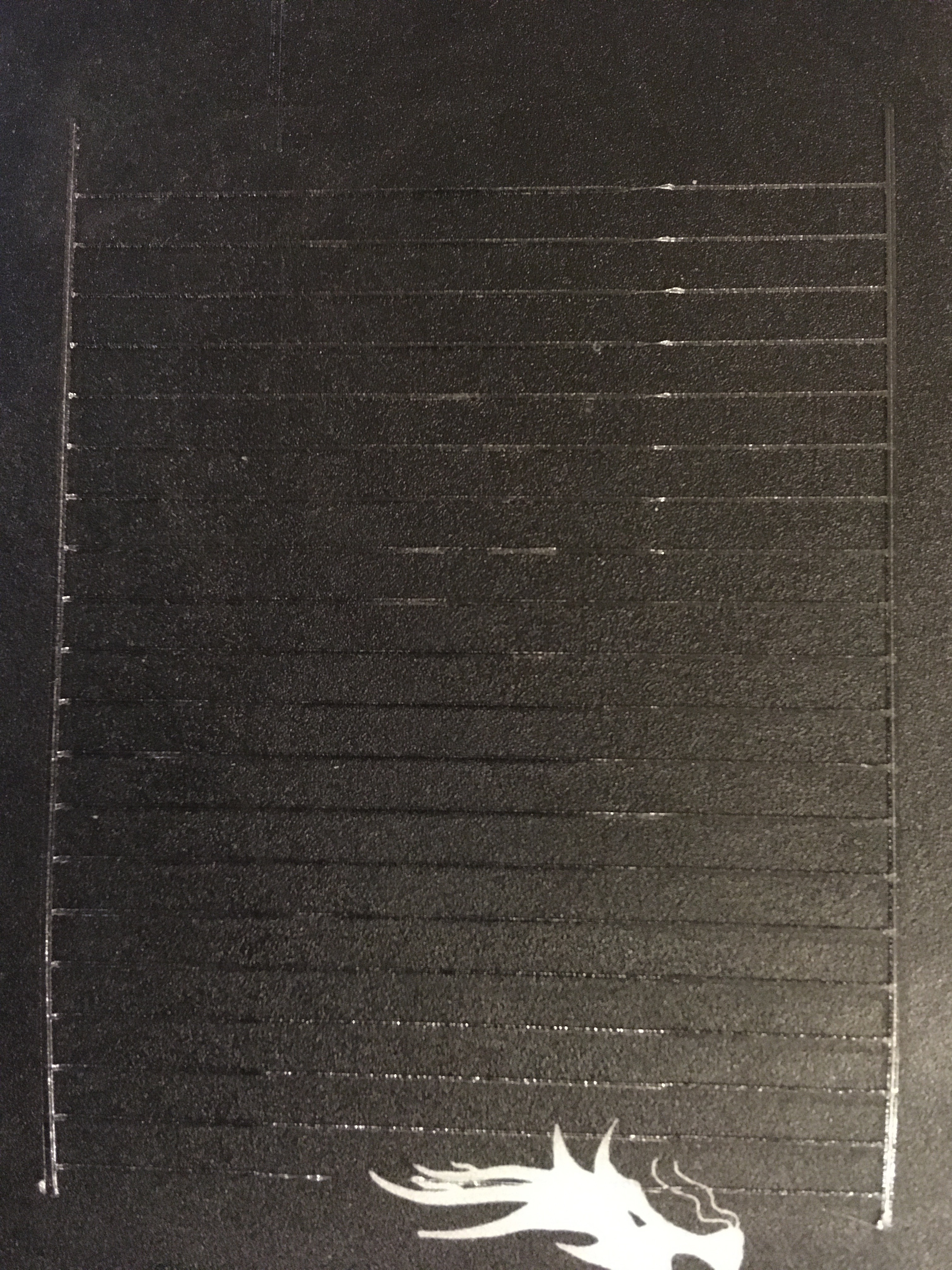
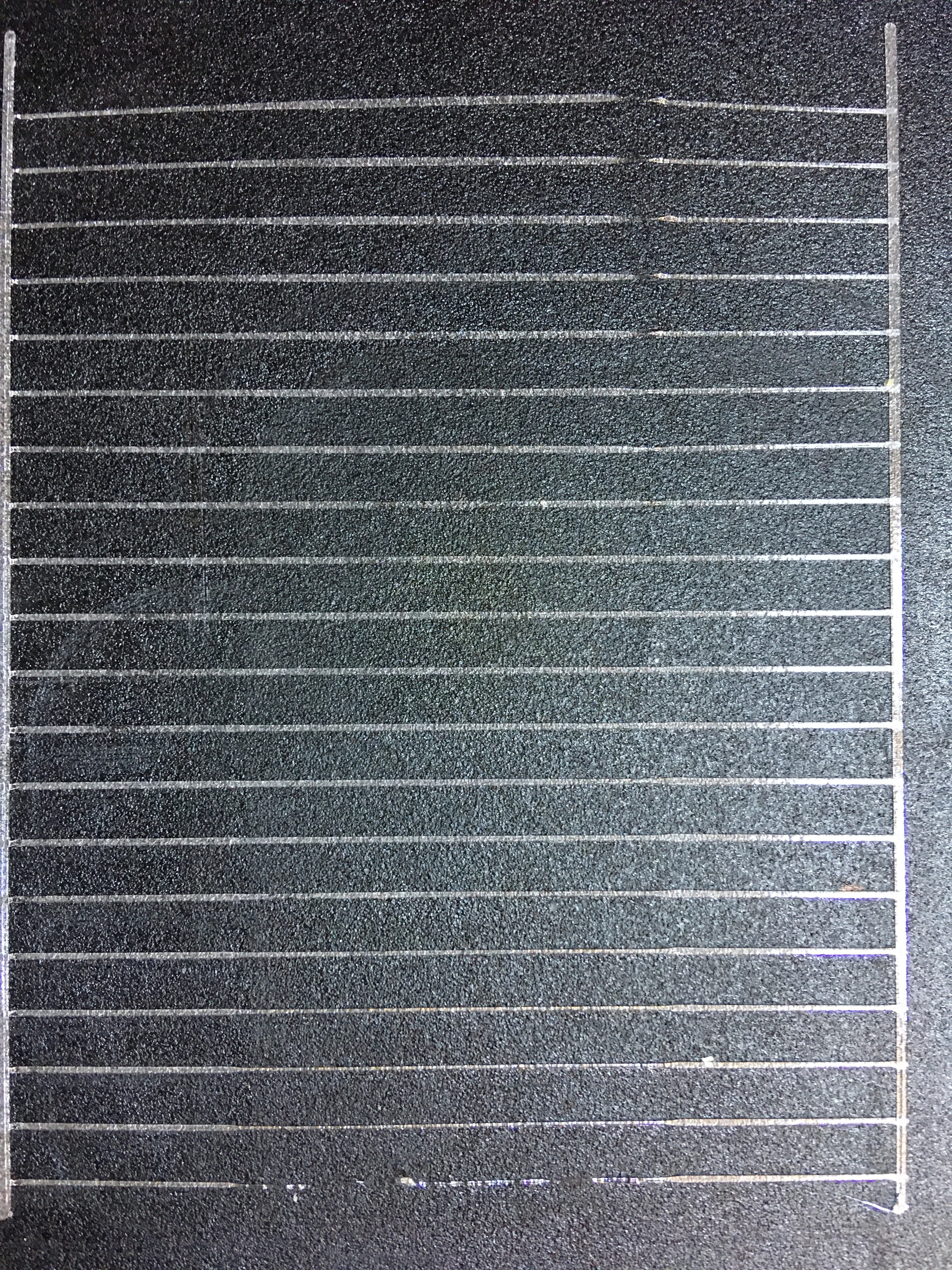
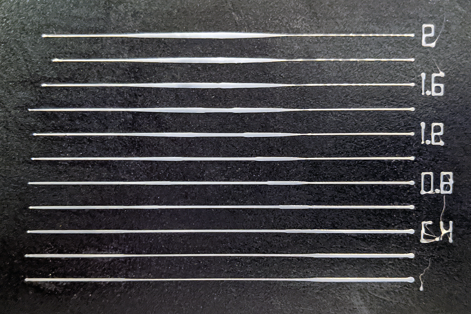
Just to see what happens, I tested it with different accelerations.
80 mm/s² 🔽
400 mm/s² 🔽

2000 mm/s² 🔽
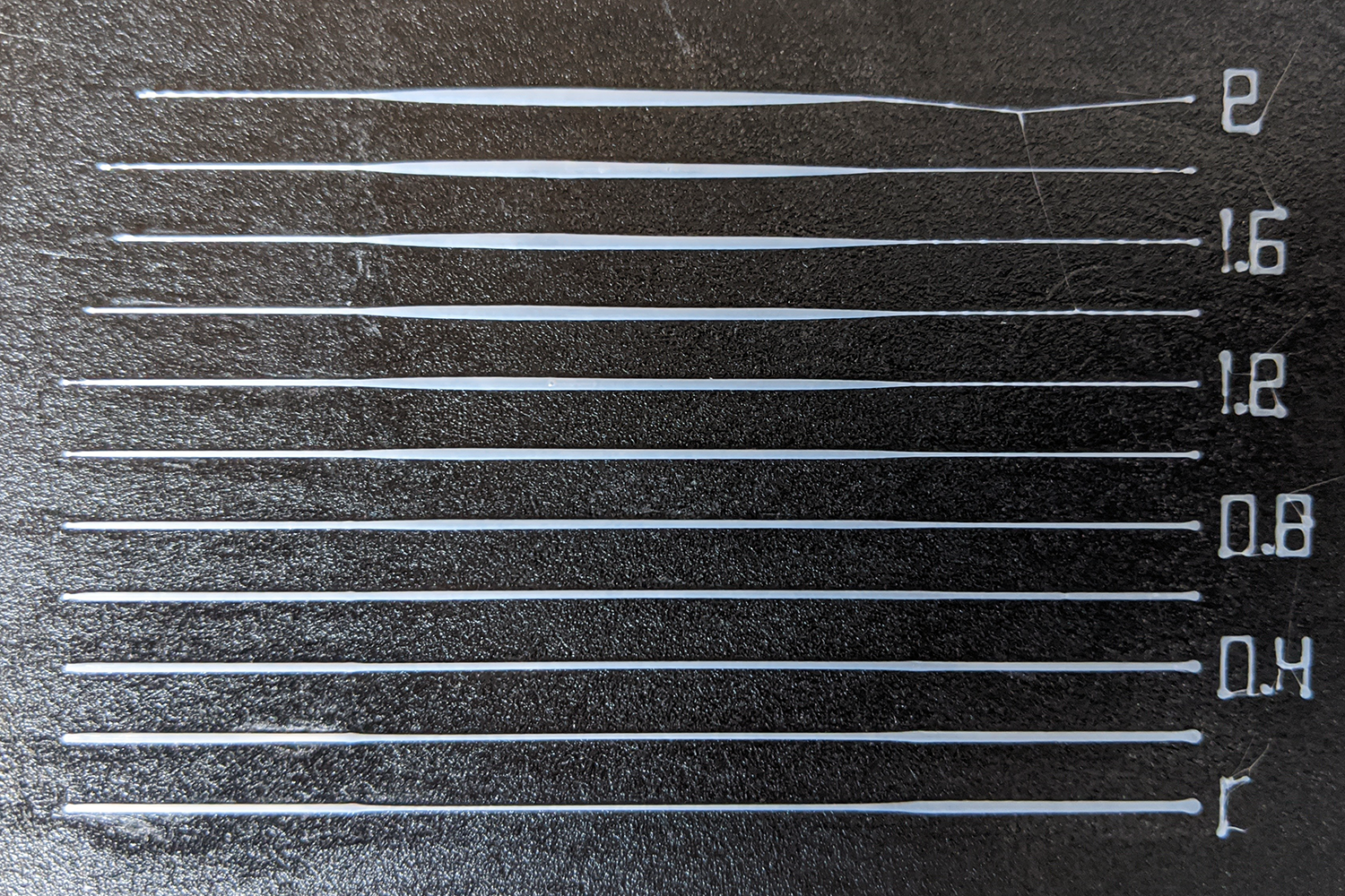
All other settings are identical (speed 20/80/20 mm/s, segment lengths and extrusion settings default, retraction 3 mm). As you can see, there is no bulge at 80 mm/s². At 400 mm/s², it's already very visible. This is a typical result for my printer. At 2000 mm/s², it's only slightly bigger than at 400.
Looking at where the bulge is placed shows, that most of it (maybe 80%) is directly after the speed change 20 mm before the end of the line. That is, after the deceleration phase, which I would have thought to be somewhat more critical.

XDA-Bam
on 26 Apr 2020
@XDA-Bam Your 2k results are exactly what I'm seeing. So it seems for LA to work worth a damn, you have to slow your printer to a crawl; which seems to defeat the purpose.
NoxIX
on 26 Apr 2020
@XDA-Bam Is S-Curve Acceleration on?
qwewer0
on 26 Apr 2020
@XDA-Bam Is S-Curve Acceleration on?
From my tests, it won't matter, the results stay the same.
NoxIX
on 26 Apr 2020
@qwewer0 No S-curve on those tests. Also, using either Jerk or JD does not make a difference, as far as I can tell.
XDA-Bam
on 26 Apr 2020
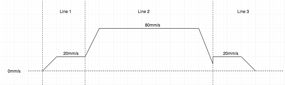
My understanding is, that the planner never moves faster than the nominal speed of a block. In case of the LA test pattern, that would mean the speed profile should look roughly like this:

So the deceleration happens right up to the 60 mm line, at which the second slow segment begins. For anybody accustomed to Marlin movement code: Is this correct?
XDA-Bam
on 27 Apr 2020
I am seeing exactly the same result with bulge in the deceleration zone.
I have tried to switch all kind of features off (including s_curve, JD), but it does not seem to matter - the blob stays present.
Is it possible that the flow decrease happens too late in relation to the deceleration? It looks like the deceleration happens and while it being decreased the flow decrease follows - but a bit too late.
- Using an Ender 3 Pro with opgraded parts and newest marlin.
 Pizzahd88
on 27 Apr 2020
Pizzahd88
on 27 Apr 2020
I'm also seeing this bulge on the LA calibration pattern regardless of K-value.
@thinkyhead Has anyone looked at Prusa Firmware to see if their algorithm is significantly different?
Looking at Prusa's stepper.cpp history, indeed they have put significant work into linear advance since merging LA v1.5 one year ago. They've made enough changes that their April 8, 2020 commit mentions "[...] removing the last vestiges of the original implementation [...]"
 jll544
on 21 May 2020
jll544
on 21 May 2020
Same issue with my E3Pro, all stock, branch 2.0.x. Printing test pattern (from marlinfw site) with K=0..2 and 0.1 step produces good results (same width) on acceleration side (left) starting at K=1. But on entire range from 0 to 2 there is bulge on slow part on right. I think this issue is mostly with Bowden setups. When accelerating, it adds pressure to keep line width, but it is not retracting fast enough (or not enough volume) on slow down (because of Bowden). In my understanding, this happen because of same amount of filament is being pushed on acceleration and retracted on slow down. Probably, Bowden needs two separate K - one for acceleration, another for slowdown. May be this will work better.
 sbasmanov
on 26 May 2020
sbasmanov
on 26 May 2020
I think this issue is mostly with Bowden setups. When accelerating, it adds pressure to keep line width, but it is not retracting fast enough (or not enough volume) on slow down (because of Bowden). In my understanding, this happen because of same amount of filament is being pushed on acceleration and retracted on slow down. Probably, Bowden needs two separate K - one for acceleration, another for slowdown. May be this will work better.
From what I'm seeing, the slowdown is not the problem. If you measure it, you will see that the blob occurs _after_ the slowdown (so, by default less than 20 mm before the end of the line). The blob appears when printing at constant speed in the beginning of the slow last segment. At least that's what I observe on my prints.
I also did a couple of experiments some weeks ago, by altering stepper.cpp and planner.cpp:
- Force LA to reduce the advance steps 2 mm earlier: Line thins during deceleration, but blob on short segment is still present.
- Force LA to reduce advance steps twice as fast: Line thins during decelration, but blob on short segment is still present.
- Increase or decrease
Konly for the deceleration phase: Various effects on line thickness, blob still present.
I'm not sure if the problem is sort of a delay, or if it rather is a hysteresis. I'm now looking into altering LA in the slow last segment, where the print head is essentially just cruising.
XDA-Bam
on 26 May 2020
To diagnose the problem further, I changed a couple of lines in stepper.cpp to slow down the increase in advance steps. Lines 2273 - 2278 by default looks like this (comment omitted):
else if (step_events_completed < decelerate_after && LA_current_adv_steps < LA_max_adv_steps) {
  LA_steps++;
  LA_current_adv_steps++;
  interval = LA_isr_rate;
}
For a 2x slowdown, I changed it to
else if (step_events_completed < decelerate_after && LA_current_adv_steps < LA_max_adv_steps) {
  if (step_events_completed % 2 == 0) {
    LA_steps++;
    LA_current_adv_steps++;
  }
  interval = LA_isr_rate;
}
So we're only increasing LA_steps on every second step.
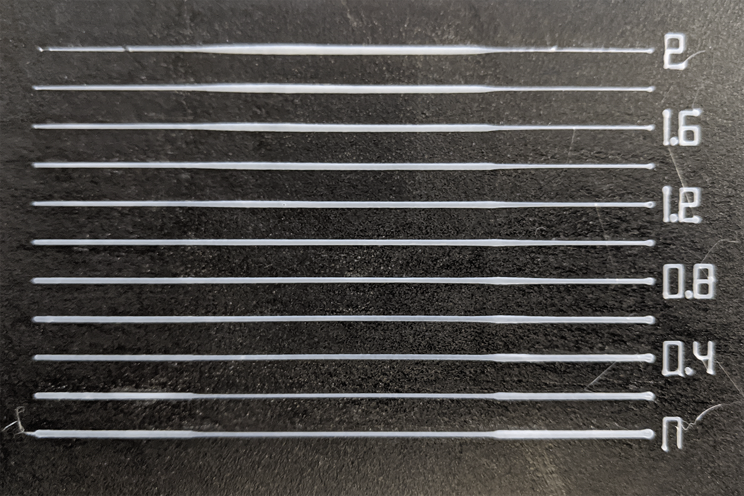
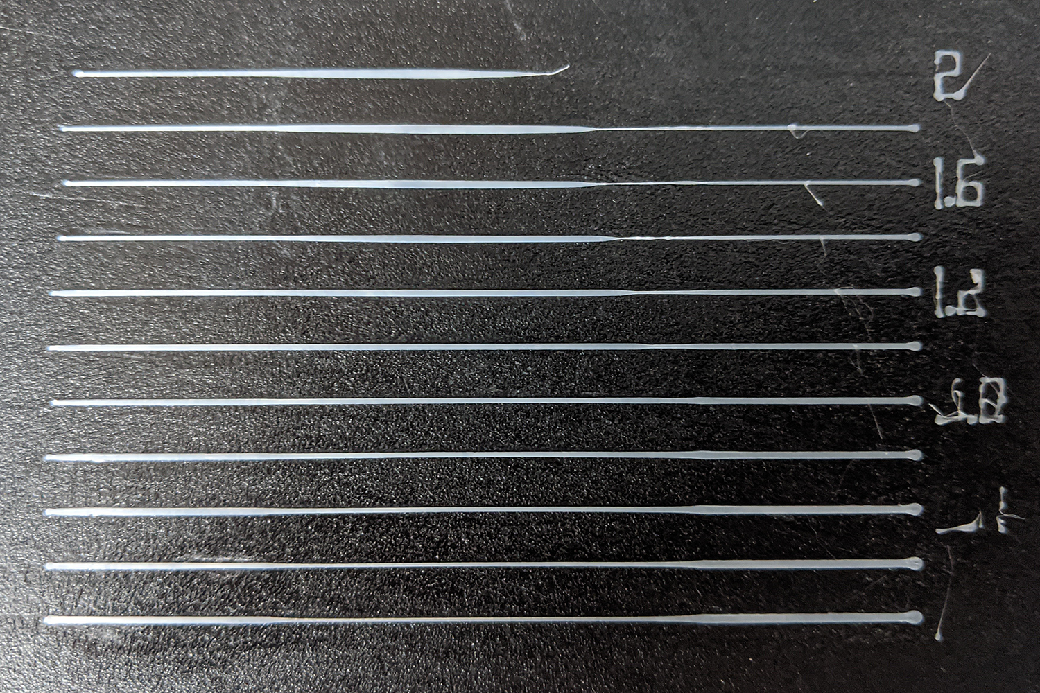
The resulting LA test pattern with the same GCode I used before looks like this:
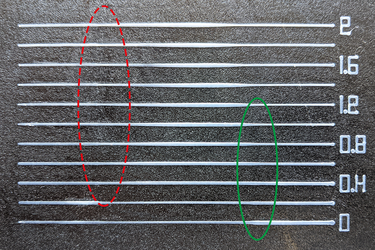
Now there's two things to note, here:
- Green ellipse 🟢 : All blobs after the slowdown are gone. The lines are not perfectly even, but damn close. Also, note that this is the coarse initial test pattern, and further tuning might result in even cleaner lines.
- Dashed red ellipse 🔴 : As a side effect of the slower advance step increase, the faster segments now suffer in the beginning. This is expected and could be rectified by _only_ applying the slower advance increase after a deceleration phase.
Conclusions:
- 80-90% of the blob is located in the slow segment (-> after a deceleration phase, not during that phase). Therefore, any fix should affect mainly the beginning of slow segments which follow on a deceleration.
- It looks like LA is increasing the advance steps too fast for segments which are preceeded by faster segments (-> after a deceleration).
- The actual cause may be a bug in the code I don't see, or it may be a mechanical oddity of the extruder system.
- I originally suspected this to be a problem exclusive to bowden setups, but direct drive users reported the same bulges in this issue.
XDA-Bam
on 26 May 2020
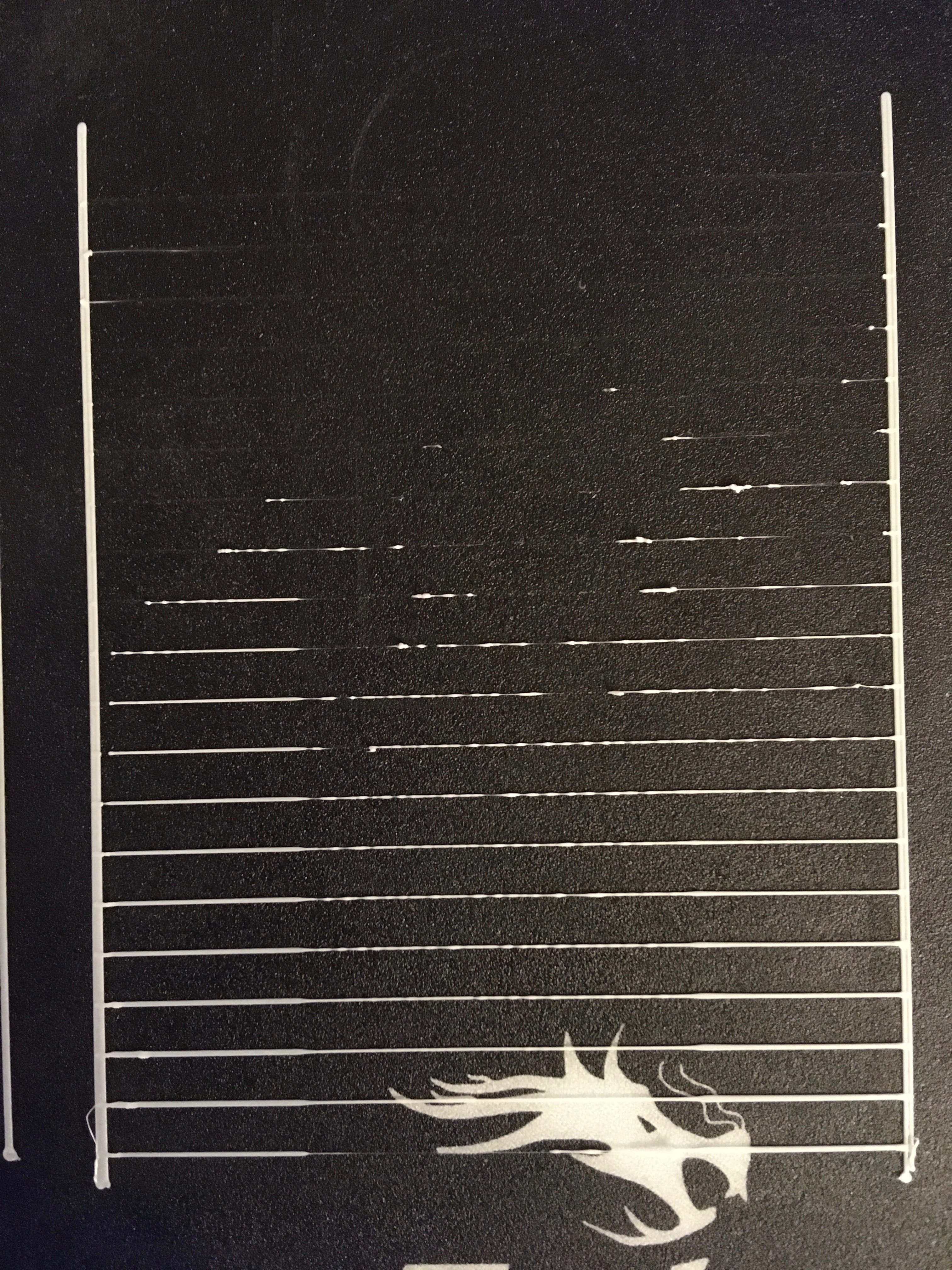
I'm not familiar with how LA works (yet), but from Your explanation I see that it's not that easy as I thought :) Anyway, for me it seems like this algorithm missing something from real world physics and this is why we have extra filament where we don't expect it. I just checked my test (from 0 to 2 with 0.1 step) and yes, all blobs appear right at the beginning of slow segment. Attached pic, sorry for poor quality.
It looks like LA is increasing the advance steps too fast for segments which are preceeded by faster segments (-> after a deceleration).
So, may be this is where second K for deceleration is needed? Seems acceleration and deceleration need different advance for some reason. And I think for different setups, it will be different. So, fixed difference won't work.
sbasmanov
on 26 May 2020
Hmm, may be I understand wrong, but this part works when accelerating?
else if (step_events_completed < decelerate_after && LA_current_adv_steps < LA_max_adv_steps) {
  if (step_events_completed % 2 == 0) {
    LA_steps++;
    LA_current_adv_steps++;
  }
  interval = LA_isr_rate;
}
Shouldn't we modify this part instead? And may be decrease steps -=2 ? So we decrease advance twice faster?
if (step_events_completed > decelerate_after && LA_current_adv_steps > LA_final_adv_steps) {
        LA_steps--;
        LA_current_adv_steps--;
        interval = LA_isr_rate;
      }
sbasmanov
on 26 May 2020
Hmm, may be I understand wrong, but this part works when accelerating?
else if (step_events_completed < decelerate_after && LA_current_adv_steps < LA_max_adv_steps) { if (step_events_completed % 2 == 0) { LA_steps++; LA_current_adv_steps++; } interval = LA_isr_rate; }
Partly wrong: It is responsible for the acceleration and cruising phase. And the latter is the one we need to modify.
Shouldn't we modify this part instead? And may be decrease steps -=2 ? So we decrease advance twice faster?
if (step_events_completed > decelerate_after && LA_current_adv_steps > LA_final_adv_steps) { LA_steps--; LA_current_adv_steps--; interval = LA_isr_rate; }
No. I tested and mentioned this in my previous post, altough I may not have stated it clear enough. It does not eliminate the blob.
Here is the result for a doubled LA_steps-- & LA_current_adv_steps--:
It helps a bit (maybe 20% less volume to the blob), but it also creates a lack of filament right before the blob, at the end of the fast segment. The main problem is the beginning of the slow segment - so the beginning of a cruising phase.
XDA-Bam
on 26 May 2020
- I originally suspected this to be a problem exclusive to bowden setups, but direct drive users reported the same bulges in this issue.
I will say, I converted my enders to direct drive to test LA, and while there may still be a bit of bulge in the test, (i've almost completely foregone using that test as a testing method) when running test towers comparing bowden to to direct drive, the direct drive towers act as one would assume. Corners bulge and Z seam bulge, then they smooth out into "sharp" corners and a, relatively, flat Z seam, and as the K value increases the corners and Z seam suck in.
When running the same test on the bowden setup, the corners and Z seam do not change, however, artifacts will begin to appear. I.E., under-extrusion due to high K values. Please note, 0 corner and Z seam change was noted from 0 to K 1.65 on bowden.
Apologies I can't help out with the firmware side of things, but hopefully that info is somewhat helpful.
NoxIX
on 27 May 2020
XDA-Bam, I was sure that LA affect only acceleration and deceleration parts of segment. Now I see that it completely handles pressure advance on entire segment. So, now I reading source to get understanding how things work. But I have strong feeling, that after deceleration, at end of segment, there is some extra pressure left in nozzle. And this volume is being over extruded on slow part, in addition to normal amount. May be logging values of LA_* variables when segment is finished will shed some light? This is what I found: https://marlinfw.org/docs/features/lin_advance.html
During the block runtime, the pressure will be advanced until the precalculated needed extra step amount is reached or the deceleration is started. During deceleration we reduce the advance step amount until we reach the amount for final speed or the block comes to an end. This checks are necessary as Marlin uses an approximation for acceleration calculation as mentioned above. Therefore, for example, we might not reach the final pressure at end of move perfectly but that’s not important as this error will not cumulate.
So, yes, it is not cumulating, but may be producing this bulb?
At Your last test 0.6 line looks very good. And under extrusion at end of fast line happen because decreasing pressure advance two times faster than it should be for this part. It corresponds to 2xK for deceleration. I feel that decrease speed of LA_current_adv_steps should be slightly faster than increase, so when segment complete, there will be zero or slightly negative pressure in nozzle.
sbasmanov
on 27 May 2020
XDA-Bam, I was sure that LA affect only acceleration and deceleration parts of segment. Now I see that it completely handles pressure advance on entire segment. So, now I reading source to get understanding how things work. But I have strong feeling, that after deceleration, at end of segment, there is some extra pressure left in nozzle.
Yes, there is a small amount of pressure left. You can see from my tests, that if this pressure is reduced to near zero (either by reducing advance steps 2 mm earlier, or by reducing them twice as fast), the bulge is reduced a little bit. Maybe by 20%, maybe it's even 30%. But it is still there.
And this volume is being over extruded on slow part, in addition to normal amount.
According to my tests, this is definietly not what's happening. Look at the results again - the bulge is still there, even if all pressure is bled from the nozzle before the slow segment begins. I am fairly certain that the problem is the increase of advance steps in the beginning of the slow segment. And reducing this increase in the slow segment has eliminated the bulge. If that doesn't prove where the problem originates, I don't know what will.
But feel free to test yourself and hopefully you will come to the same conclusion. Four eyes do see more than two.
May be logging values of LA_* variables when segment is finished will shed some light?
That will certainly be helpful.
This is what I found: https://marlinfw.org/docs/features/lin_advance.html
...
So, yes, it is not cumulating, but may be producing this bulb?At Your last test 0.6 line looks very good. And under extrusion at end of fast line happen because decreasing pressure advance two times faster than it should be for this part. It corresponds to 2xK for deceleration.
Yes, that's why the underextrusion happens. And at that point, right at the 60 mm mark, there will be very little pressure left in the nozzle - we're printing with zero advance at high speeds. And yet, the bulge is still there in the small segment!
I feel that decrease speed of LA_steps should be slightly faster than increase, so when segment complete, there will be zero or slightly negative pressure in nozzle.
I agree somewhat: We will probably need to _also_ increase the reduction of advance steps while decelerating to totally fix our issue. But you can try - my tests show, that we won't get rid of the bulge this way. It helps, but only a small amount. We will also need to slow down the increase of advance steps directly after the deceleration, during the cruising phase.
XDA-Bam
on 27 May 2020
Hmm... Here is our line:
G1 X85 Y37.5 E0.7982 F1200 ; print line
G1 X125 Y37.5 E1.5965 F4800 ; print line
G1 X145 Y37.5 E0.7982 F1200 ; print line
First (slow) segment starts from zero, and last segment starts from some non-zero speed? And LA doesn't take this into account and calculating advance steps like if we start from zero?
sbasmanov
on 27 May 2020
Not sure if LA assumes that we start from zero speed. But step_events_completed < decelerate_after (in this line) is certainly true at the 60 mm mark (beginning of second slow segment). And LA_current_adv_steps < LA_max_adv_steps seems to be true, too. Otherwise, my fix/hack with the slower step increase wouldn't work.
I assumed, that LA_current_adv_steps = LA_max_adv_steps at the beginning of the second slow segment: The final speed at the end of the fast segment is exactly the same as the speed at the beginning of the slow one. Consequently, the number of advance steps should be the same, right? 🤔
Of yourse, that would only be true, if the current advance steps are carried over from one segment to the next. If they are forgotton each time the segment changes, LA_current_adv_steps = 0 would be true at the beginning of the last slow one. Which is it?
XDA-Bam
on 27 May 2020
Hmm.. that's good question. In my understanding, there should be no advance at all at beginning of second slow segment, as we are already at cruise speed and extruder feeds proper amount of filament. Here is how I see this:
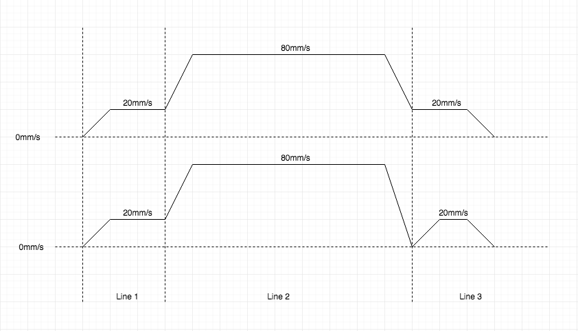
First graph show how it really goes, and second how LA interprets it and pushing some extra filament on beginning of second slow segment like if it was starting from zero. I don't know (yet) if this is what happen, but this my suggestion.
So, seems You're right - there should be no advance at beginning of second slow segment.
So, definitely, we need to log all LA_* values at start and end of each segment. This will give us more information on what's going on.
sbasmanov
on 27 May 2020
Hmm.. that's good question. In my understanding, there should be no advance at all at beginning of second slow segment, as we are already at cruise speed and extruder feeds proper amount of filament.
Not 100% sure, but yeah. Looks like there's a problem.
First graph show how it really goes, and second how LA interprets it and pushing some extra filament on beginning of second slow segment like if it was starting from zero. I don't know (yet) if this is what happen, but this my suggestion.
That's a nice way to visualize it.
XDA-Bam
on 27 May 2020
So, this is what I see in planner:
            #if ENABLED(LIN_ADVANCE)
              if (block->use_advance_lead) {
                const float comp = block->e_D_ratio * extruder_advance_K[active_extruder] * settings.axis_steps_per_mm[E_AXIS];
                block->max_adv_steps = current_nominal_speed * comp;
                block->final_adv_steps = next_entry_speed * comp;
              }
            #endif
and in stepper:
      // Initialize the trapezoid generator from the current block.
      #if ENABLED(LIN_ADVANCE)
        #if DISABLED(MIXING_EXTRUDER) && E_STEPPERS > 1
          // If the now active extruder wasn't in use during the last move, its pressure is most likely gone.
          if (stepper_extruder != last_moved_extruder) LA_current_adv_steps = 0;
        #endif
        if ((LA_use_advance_lead = current_block->use_advance_lead)) {
          LA_final_adv_steps = current_block->final_adv_steps;
          LA_max_adv_steps = current_block->max_adv_steps;
          initiateLA(); // Start the ISR
          LA_isr_rate = current_block->advance_speed;
        }
        else LA_isr_rate = LA_ADV_NEVER;
      #endif
So, final_adv_steps of fast segment must be same as max_adv_steps of last slow segment. In this case no extra E steps will be executed. But how we can check if this is true?
And yes, it seems that LA_current_adv_steps always starts from zero. Somehow, it must inherit value from previous block.
sbasmanov
on 27 May 2020
Is there any place at stepper/planner where we can pull LA_current_adv_steps from previous block?
sbasmanov
on 27 May 2020
s there any place at stepper/planner where we can pull LA_current_adv_steps from previous block?
No.
LA_current_adv_steps is a privat from stepper class - it's existing only once.
Maybe you can save it to an new variable when leaving/deleting or entering a block.

The second graph is looking as if the third block is not properly connected to the second. This will (for example) happen when the second block is already stepped when the third is planned (planner buffer not full enough).
 AnHardt
on 27 May 2020
AnHardt
on 27 May 2020
is a privat from stepper class.
Maybe you can save it to an new variable when leaving/deleting a block.
Memory scope is always confuse me:( So, is it keeps its value since initialized at startup? Or being reset to zero each time? And if reset - when this happen? I can't find any assignment in code except declaration.
As to second graph - it is my vision of how advance is calculated. This blob looks like more E steps was executed at beginning of last segment as if it was starting from zero speed (with acceleration). So, it's not reflecting real motion :)
sbasmanov
on 27 May 2020
      #if ENABLED(LIN_ADVANCE)
        #if DISABLED(MIXING_EXTRUDER) && E_STEPPERS > 1
          // If the now active extruder wasn't in use during the last move, its pressure is most likely gone.
          if (stepper_extruder != last_moved_extruder) LA_current_adv_steps = 0;
        #endif
When setting up a new block LA_current_adv_steps should have the value left over from the previous.
AnHardt
on 27 May 2020
When setting up a new block LA_current_adv_steps should have the value left over from the previous.
Yes, that's what I thought. But here (https://marlinfw.org/docs/features/lin_advance.html) it says:
Therefore, for example, we might not reach the final pressure at end of move perfectly but that’s not important as this error will not cumulate.
That means to me that LA_current_adv_steps is being reset every block. Or am I getting it wrong? There is no other place in code where it sets value of LA_current_adv_steps. So, how do I find out value of LA_current_adv_steps at block setup? If I properly understand how things work, at beginning of last slow segment LA_current_adv_steps must equal LA_max_adv_steps so no extra E steps executed. But not sure if this is true.
sbasmanov
on 27 May 2020
Yes, that's what I thought. But here (https://marlinfw.org/docs/features/lin_advance.html) it says:
Don't go by what the documentation says it should do. Go by what the code is actually doing 😉
When setting up a new block
LA_current_adv_stepsshould have the value left over from the previous.
In that case, it's probably best to check whether this is actually the case when printing the LA test pattern. So, as @sbasmanov suggested, we need to debug it while running. I'm still waiting for a cable to be able to set this up on my printer, so I can't help with that right now.
XDA-Bam
on 27 May 2020
My guess is that the error is not accumulating because the error is transferred to the new block via LA_current_adv_steps. In the new block that number of additional steps is done to reach the new value. (At least, i guess, that is the plan.)
AnHardt
on 27 May 2020
I'm still waiting for skr board, as mine (original) behave very strange - after two-three times I update firmware it may stop booting at all, so I have to connect Pi, erase, flash bootloader and only after it will work again. So, I don't want to touch it while it works :)
But I think we can try to simulate this situation if we can figure out at block setup if we already at cruise speed and there is no need to accelerate. If this is possible, we can put 'LA_current_adv_steps=LA_max_adv_steps' right after setup, after line 2150: https://github.com/MarlinFirmware/Marlin/blob/6c994002af1ef13004490b5e15501e6cdc70dd88/Marlin/src/module/stepper.cpp#L2150
sbasmanov
on 27 May 2020
In the new block that number of additional steps is done to reach the new value. (At least, i guess, that is the plan.)
That looks like real. So, probably in case when no acceleration is needed and head already at cruising speed, we don't want these extra steps to be executed. Am I right? That means LA_current_adv_steps==LA_max_adv_steps must be true.
sbasmanov
on 27 May 2020
My guess is that the error is not accumulating because the error is transferred to the new block via
LA_current_adv_steps. In the new block that number of additional steps is done to reach the new value. (At least, i guess, that is the plan.)
I think it doesn't accumulate, because we increase LA_current_adv_steps until we reach LA_max_adv_steps in _each_ block. At that point, the error will be zero again. Maybe we're saying the same thing, not sure.
However, regardless of the error we start out with at the beginning of a block (which is only non-zero, if LA_final_adv_steps has not been reached), the code always increases LA_current_adv_steps until the desired value is reached. So, if LA_final_adv_steps has not been reached in the last block, LA_current_adv_steps will be too high in the current one - and we will also begin to increase it right away. In that case, our advance will be consistently too high from some point in the deceleration phase of the last block, until a couple of steps _after_ we reach LA_max_adv_steps in our current block. That's not good.
I assume that the opposite case - LA_final_adv_steps being undercut and LA_current_adv_steps being too low at the start of the next block - should never happen. At least I don't currently see how it could.
XDA-Bam
on 27 May 2020
So, if LA_final_adv_steps has not been reached in the last block, LA_current_adv_steps will be too high in the current one - and we will also begin to increase it right away.
It will not increase as it will increment only when LA_current_adv_steps < LA_max_adv_steps and LA_max_adv_steps should be same as LA_final_adv_steps from previous block.
Anyway, I think that value of LA_current_adv_steps is not root of problem. Remember, when You decreased it twice faster? It was definitely reaching LA_final_adv_steps before end of block. And that didn't affected blob significantly. That means, even if LA_current_adv_steps reached LA_final_adv_steps and next block have same value of LA_max_adv_steps (so no extra E steps), there is still too much pressure in nozzle. And this is where I think that pressure should go lower than needed in next block. Here is what I mean:
May be we should adjust final_adv_steps in planner, so it is less than max_adv_steps of next block?
              if (block->use_advance_lead) {
                const float comp = block->e_D_ratio * extruder_advance_K[active_extruder] * settings.axis_steps_per_mm[E_AXIS];
                block->max_adv_steps = current_nominal_speed * comp;
                block->final_adv_steps = next_entry_speed * comp;
For test it could be:
if(next_entry_speed < current_nominal_speed) block->final_adv_steps = next_entry_speed * comp * 0.5;
else block->final_adv_steps = next_entry_speed * comp;
At least we will see how it will affect blob (and where).
sbasmanov
on 27 May 2020
It will not increase as it will increment only when LA_current_adv_steps < LA_max_adv_steps and LA_max_adv_steps should be same as LA_final_adv_steps from previous block.
True, in our case it should not increase it further. LA_current_adv_steps might still be too high (>LA_max_adv_steps), though. This was more of a general idea - it might not happen in our case, but it looks like a possible bug in LA.
Anyway, I think that value of LA_current_adv_steps is not root of problem. Remember, when You decreased it twice faster? It was definitely reaching LA_final_adv_steps before end of block. And that didn't affected blob significantly.
True. But that only tells us that LA_current_adv_steps = LA_final_adv_steps is reached at the end of the fast block. It does not tell us what happens to LA_current_adv_steps at the beginning of the second slow block. I still think that our problem originates there.
That means, even if LA_current_adv_steps reached LA_final_adv_steps and next block have same value of LA_max_adv_steps (so no extra E steps), there is still too much pressure in nozzle.
But my tests also show, that LA_current_adv_steps seems to be increased at the beginning of the last slow block, because halving the increase rate got rid of the blobs 🤔 It shouldn't happen - you're right. But it seems to me, that it does happen nonetheless. Maybe you should test it, too. Maybe there was a problem with my machine or test method.
XDA-Bam
on 27 May 2020
True. But that only tells us that LA_current_adv_steps = LA_final_adv_steps is reached at the end of the fast block. It does not tell us what happens to LA_current_adv_steps at the beginning of the second slow block. I still think that our problem originates there.
If I understand properly, Stepper class is not initialized on start of each block. It means that LA_current_adv_steps keeps its value where it was at end of previous block. And look at planner, how it calculates values for current block:
                block->max_adv_steps = current_nominal_speed * comp;
                block->final_adv_steps = next_entry_speed * comp;
So, for fast block, final_adv_steps will be same as max_adv_steps for slow block, when it will come to this point at planner. So, here will be no additional E steps.
But my tests also show, that LA_current_adv_steps seems to be increased at the beginning of the last slow block, because halving the increase rate got rid of the blobs 🤔 It shouldn't happen - you're right. But it seems to me, that it does happen nonetheless. Maybe you should test it, too. Maybe there was a problem with my machine or test method.
Well, we don't know if it increasing or not until we log this values. Now we can only guess :) Here is what I think about this: when accelerating, we increase E speed in advance, that means more filament coming to extruder. To handle this, more heat is needed to melt increased amount of filament. This raises nozzle temperature to compensate this. When we slowing down, we lowering extrusion speed, but nozzle (and filament) can't cool down with same speed. So, extra filament still coming from nozzle even if we are at right (slower) extruder speed. What I'm trying to say, that K for advance when accelerating and K when decelerating is not same. We should reduce extrusion amount slightly more than we added in advance on acceleration. I think it will be small difference in K1,K2 on direct setup, but significant on Bowden.
Here is how I think pressure (blue line) is rising and lowering when E speed is changed:
And there is another caveat - isr interval is calculated at planner for entire block. If we want to try decreasing LA_current_adv_steps with different speed (compared to how it was increased), we should adjust this interval as well, to let isr count down to `LA_final_adv_steps'.
ps: I'll definitely do my tests as soon as I get my skr board. As I mentioned before, my creality board behaves very strange, so I don't want to brick it now, when I don't have replacement. So, if You have time for tests, try to change final_adv_steps value calculation as I proposed above? Oh, and here https://github.com/MarlinFirmware/Marlin/blob/6c994002af1ef13004490b5e15501e6cdc70dd88/Marlin/src/module/stepper.cpp#L2267 we need to adjust decrement, to reach lowered LA_final_adv_steps. I think it could be:
if (step_events_completed > decelerate_after && LA_current_adv_steps > LA_final_adv_steps) {
        if (step_events_completed % 2 == 0) {
           LA_steps-=2;
           LA_current_adv_steps-=2;
        } else {
           LA_steps--;
           LA_current_adv_steps--;
        }
        interval = LA_isr_rate;
      }
Yes, it will reach LA_final_adv_steps faster than needed, but for test may be will work :)
sbasmanov
on 27 May 2020
So, for fast block, final_adv_steps will be same as max_adv_steps for slow block, when it will come to this point at planner. So, here will be no additional E steps.
I agree that this should be the case. That's what I would expect seeing the code. Also agree that we need to debug to see if it is as expected when actually printing.
What I'm trying to say, that K for advance when accelerating and K when decelerating is not same. We should reduce extrusion amount slightly more than we added in advance on acceleration. I think it will be small difference in K1,K2 on direct setup, but significant on Bowden.
Mostly agree. Not sure if this will "cure" the blobs, but we will see.
So, if You have time for tests, try to change final_adv_steps value calculation as I proposed above?
Tested it a couple of weeks ago. I forced K +-0.4 and +-0.5 (more or less randomly chosen) for the deceleration phase only. Both changes seemed to make the blobs worse and had unwanted side effects (slow lines super thin or super thick). I'm not totally happy with the tests though. Might repeat them in the coming days.
The 'LA_steps-=2;'-stuff is also something I tested and which resulted in this image. So, a little better but not solved.
Looking forward to your new board and my damn cable 😀
XDA-Bam
on 27 May 2020
The 'LA_steps-=2;'-stuff is also something I tested and which resulted in this image. So, a little better but not solved.
Seems twice faster is too much. We need to decrease LA_steps with something like x0.8 x1.2 of normal speed or fire isr more frequently. But this will have effect only with lowering of LA_final_adv_steps for fast segment, so at end we remove little more pressure than needed. And because LA_current_adv_steps will be low as well, it will start incrementing at beginning of slow segment to get to proper level.
Anyway, my board arrive in two weeks (I hope), so there is enough time to think :)
sbasmanov
on 27 May 2020
Got the cable and did some initial testing. This is what LA_current_adv_steps looks like for each call of Stepper::advance_isr during printing a pretty typical test pattern (20/40/20 mm segment length, 20 mm/s slow, 80 mm/s fast, accel. 750 mm/s², K=0 - 2.0 in 0.2 steps):
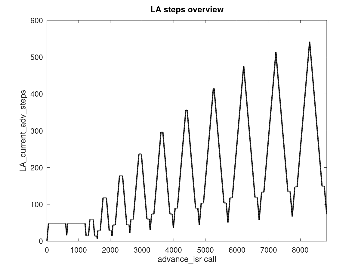
The two long plateaus at the beginning should be the nozzle purging / priming. Notice that there are 11 calibration lines (K=0 to 2.0), but only 10 peaks follow - I guess K=0 does not produce any changes to LA_current_adv_steps, which kind of makes sense. Other than the fact that the lowest LA_current_adv_steps reached inbetween each of the calibration lines increases continously, it looks good to me.
Now, investigating one peak in more detail. Let's pick the second one after the plateaus, which should be K=0.4:
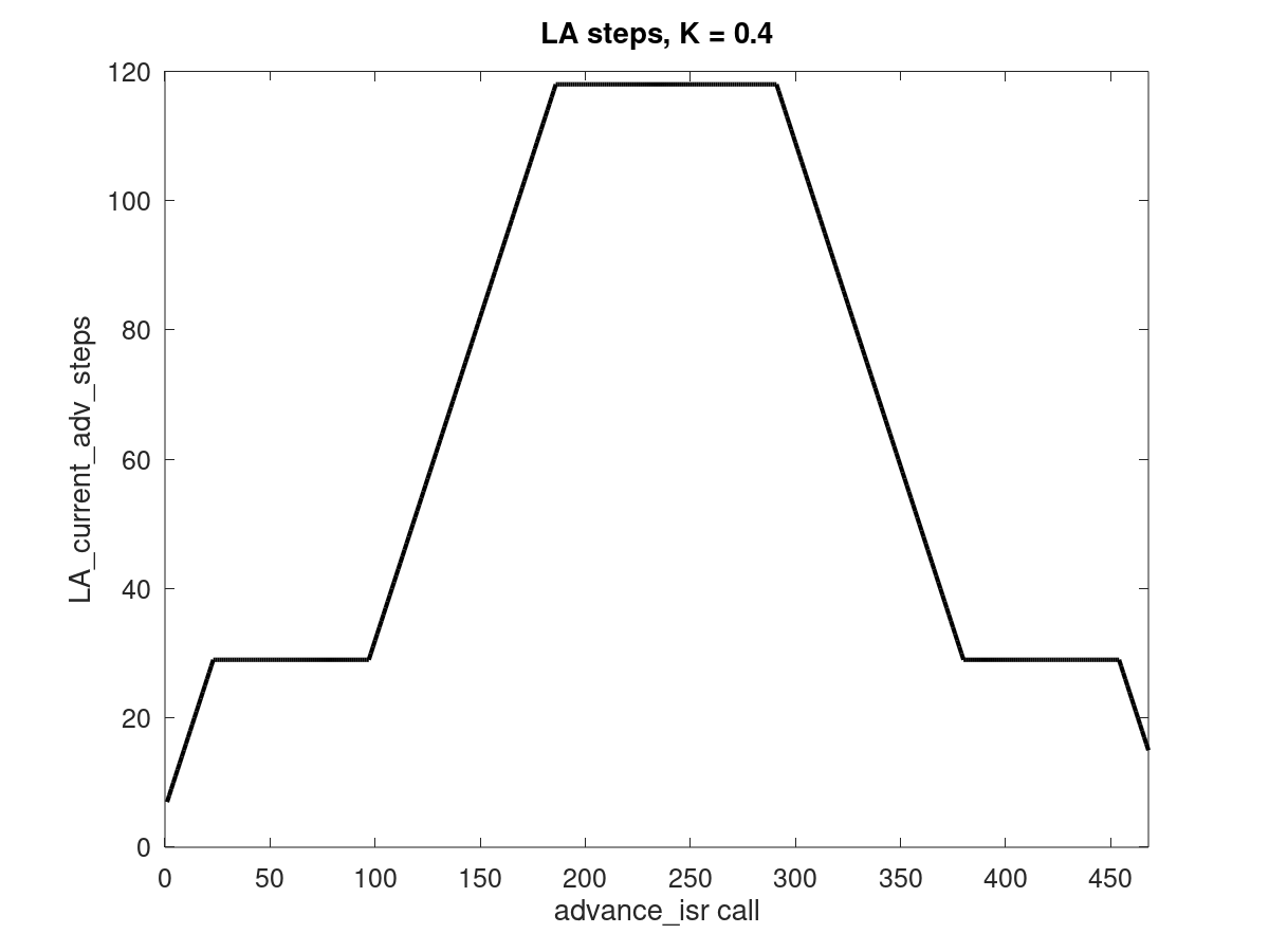
I have to say - this is more boring than expected 😄 Looks to me as it should. No unexpected increases, no bumps or drops, all good.
The value of the low plateaus before and after the peak, corresponding to the slow segments, are both "29". Therefore, LA_current_adv_steps seems to reach LA_final_adv_steps just fine. It's also pretty clear that it reaches LA_max_adv_steps for the first couple of peaks and probably doesn't for the later ones - there is no visible plateau at the top of those.
XDA-Bam
on 29 May 2020
Oh, such useful information. Many thanks. I expected something similar :) While I still digging back & forth in code to get understanding in details, here is what I found so far:
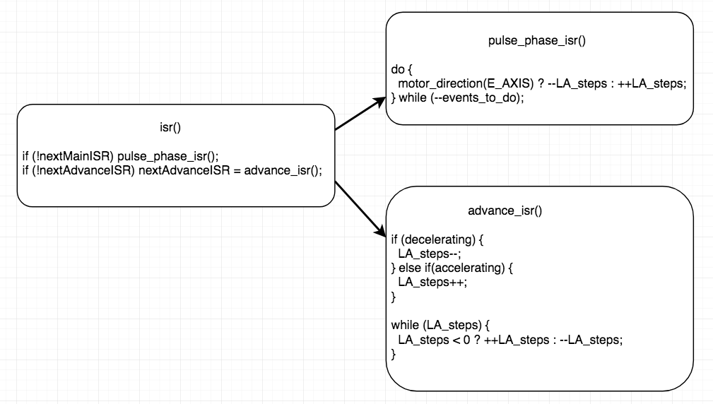
So, pulse_phase_isr is just altering LA_steps and not doing actual pulses. Next, advance_isr is called and this is where it fires all pending pulses. In case we're accelerating/decelerating it additionally alters LA_steps adding/removing extra pulses. While cruising, LA_steps altered only at pulse_phase_isr.
Ok, another thing. There is advance_speed that is being calculated using K (and lot of other stuff). And according to this speed, advance_isr frequency is set. And of course, this speed is absolutely same for acceleration and deceleration. And this is where I think problem comes from: on acceleration we fed a lot of filament in Bowden tube and now, when we lowering speed, this filament straightens up which is resulting in that bulge. I'm still thinking we could try setting final_adv_steps to x0.8 (with if(next_entry_speed < current_nominal_speed) ) value and see if LA_current_adv_steps will count down to it. https://github.com/MarlinFirmware/Marlin/issues/16880#issuecomment-634761609
ps: what cable, board and software you're using to get values from running board? I definitely need same :)
sbasmanov
on 29 May 2020
It's also pretty clear that it reaches LA_max_adv_steps for the first couple of peaks and probably doesn't for the later ones - there is no visible plateau at the top of those.
Yes, with higher K it starts going down without reaching cruise value. With high enough K it starts retracting (LA_steps becomes negative).
sbasmanov
on 29 May 2020
ps: what cable, board and software you're using to get values from running board? I definitely need same :)
I'm running a stock Ender 3 Pro (Creality Melzi v1.1.4 board, ATMega 1284p, A4988 drivers) and got a no-name USB-ASP as programmer. Serial console is done via the regular Ender 3 mini USB port. "The cable" I was waiting for was a USB extender, so I don't have to lay my printer flat to reach my PC's front USB 😉
XDA-Bam
on 29 May 2020
Ok, so, flashed my board with two different values. Once, avrdude lost connection right in the middle. But this time boot loader survived, so I restarted flashing :)
if(next_entry_speed < current_nominal_speed) \
 block->final_adv_steps = next_entry_speed * comp * 0.8;
else block->final_adv_steps = next_entry_speed * comp;
And
if(next_entry_speed < current_nominal_speed) \
  block->final_adv_steps = next_entry_speed * comp * 0.5;
else block->final_adv_steps = next_entry_speed * comp;
I wonder, how far I can go? x0.1? :)
sbasmanov
on 29 May 2020
Go limbo 😉
But looks like the bulge is mostly unchanged, but slow second segment just becomes thicker and thicker. Mostly like in my old tests. I suppose LA_current_adv_steps is increased immediately after the second slow segment begins, because at that moment, it is lower than LA_max_adv_steps. Will also debug this soon.
XDA-Bam
on 29 May 2020
Just want to weigh in.
I had this issue and it was bad.
I have now changed filament and thereby changed the retraction, temperature, adjusted flowrate a bit etc.
now the bulge is almost gone.
The machine has not been altered in the meantime, which makes me believe that it is possible to change settings/filament and achieve fine results in the calibration pattern.
BUT, the bulge is still there - it is just very small now.
Don’t know what was causing it of all the changes.
Pizzahd88
on 29 May 2020
But looks like the bulge is mostly unchanged, but slow second segment just becomes thicker and thicker. Mostly like in my old tests. I suppose LA_current_adv_steps is increased immediately after the second slow segment begins, because at that moment, it is lower than LA_max_adv_steps. Will also debug this soon.
Seems I know why it doesn't affect bulge. Because LA_current_adv_steps never reach such low final_adv_steps. We should definitely change advance_speed to higher value when decelerating. And this https://github.com/MarlinFirmware/Marlin/blob/6c994002af1ef13004490b5e15501e6cdc70dd88/Marlin/src/module/stepper.cpp#L1917 seems right place to do it.
sbasmanov
on 29 May 2020
Next test.
if(next_entry_speed < current_nominal_speed) \
 block->final_adv_steps = next_entry_speed * comp * 0.8;
else block->final_adv_steps = next_entry_speed * comp;
and
LA_isr_rate = (int) (current_block->advance_speed * 0.8);
We're on right way? :)
ps: how to log LA_ values from isr?
sbasmanov
on 29 May 2020
Looks promising!
ps: how to log LA_ values from isr?
Just add
SERIAL_ECHO(LA_current_adv_steps);
SERIAL_EOL();
or
SERIAL_ECHOPAIR("Final steps: ",LA_final_adv_steps);
SERIAL_EOL();
after those have been set/changed.
XDA-Bam
on 29 May 2020
Shouldn't it be LA_isr_rate = (int) (current_block->advance_speed * 1.25);, meaning /0.8 instead of *0.8? We want LA to reduce the steps quicker not slower, right?
XDA-Bam
on 29 May 2020
I set values to x0.5 and made two pictures:
Here is visible places with bad adhesion - probably not enough filament.
And this how it looks after I took it off from bed:
Notice last 5 lines - it makes under extrusion with K >1.5 :)
So, on last pic lines 0.9 and 1.0 look like it should be.
Shouldn't it be LA_isr_rate = (int) (current_block->advance_speed * 1.25);, meaning /0.8 instead of *0.8? We want LA to reduce the steps quicker not slower, right?
This is timer interval, so shorter values mean more frequent call. May be I made mistake when been talking about speeds :)
sbasmanov
on 29 May 2020
OK, makes sense. Maybe we should not correct so hard (0.5 seems quite extreme). Could be cleaner to use a factor of 0.7 or so and additionally slow down the increase of LA_current_adv_steps in the following segment by adding
else if (step_events_completed < decelerate_after && LA_current_adv_steps < LA_max_adv_steps) {
  LA_steps++;
  LA_current_adv_steps++;
  if (current_block->initial_rate == current_block->nominal_rate)
    interval = (int)  (LA_isr_rate * 1.428f); // =1/0.7f
  else
    interval = LA_isr_rate;
}
So, the bottom line: it seems that on Bowden setups pressure drops slower than increasing, so extra E steps should be executed (comparing to acceleration). I think solution is:
- adding second K, let's say Kd (deceleration)
- adding
deceleration_advance_speedto block structure - calculating
final_adv_stepswith Kd - setting
advance_isr()rate withdeceleration_advance_speedon deceleration to match steps withfinal_adv_steps
I think there is another way to check pressure drop speed: print 3 segments with K=0, 20-40-20 with same feedrate (F) but with different line width, let's say 0.8 (means more E steps) in middle. Then measure distance, where last segment become normal width. I bet it will be somewhere at ~18mm from end :)
OK, makes sense. Maybe we should not correct so hard (0.5 seems quite extreme). Could be cleaner to use a factor of 0.7 or so and additionally slow down the increase of LA_current_adv_steps in the following segment by adding
I took 0.5 to get contrast.
Hmm.. Not sure if increasing isr intervals will do the trick, but worth trying. May be together this will produce expected result. But anyway, this changes have to be user adjustable. We can't just hardcode them :)
sbasmanov
on 29 May 2020
But anyway, this changes have to be user adjustable. We can't just hardcode them :)
Of course. Also, I'd argue that this is a hysteresis behaviour, so I would introduce something like K_hyst and define K_accel = K as well as K_decel = K-K_hyst. Other vars as you suggested. That way, K_hyst can default to zero for all configs and users only need to tune it, if The Blob ™️ appears.
XDA-Bam
on 29 May 2020
I think there is another way to check pressure drop speed: print 3 segments with K=0, 20-40-20 with same feedrate (F) but with different line width, let's say 0.8 (means more E steps) in middle. Then measure distance, where last segment become normal width. I bet it will be somewhere at ~18mm from end :)
Either I don't understand how G-code works, or I don't understand something else :) Tried to print this code:
G1 E3 F1500 ; un-retract
G1 X85 Y37.5 E0.7982 F1200 ; print line
G1 X125 Y37.5 E3.193 F1200 ; print line
G1 X145 Y37.5 E0.7982 F1200 ; print line
G1 E-3 F1500 ; retract
with E for middle part twice more, but got this result:
But even if it tried to push twice more filament into middle segment, I don't see where it ends :)
Of course. Also, I'd argue that this is a hysteresis behaviour, so I would introduce something like K_hyst and define K_accel = K as well as K_decel = K-K_hyst.
Well, this can be any way. I was thinking about second K: 0 < K < 1 And it will 1 by default. Math is not my strongest side, so may be somebody with more math skills will give us advice :)
The Blob ™️
The LA Blob ™️ - most famous blob :)
So, what to do next? Writing patch or looking for other ways to solve this? I admit that I may be getting things wrong, so may be there are more proper and elegant way to fix the blob.
sbasmanov
on 29 May 2020
I'd say next step would be to program a "clean" solution and make a pull request to bugfix-2.0.x branch.
But I also just tried your changes with a factor of 0.7 and got the following result:
I think that doesn't look like it should. Also, either my extruder or my X stepper sounds really unhealthy on the lines with K>0. Maybe we are disrespecting some acceleration or jerk limit by hardcoding these values? 🤔
Just to be sure, this is what I changed: In planner.cpp, I changed line 1182 to
if(next_entry_speed < current_nominal_speed)
  block->final_adv_steps = next_entry_speed * comp * 0.7f;
else
  block->final_adv_steps = next_entry_speed * comp;
In stepper.cpp, I changed line 1917 to
LA_isr_rate = (int) (current_block->advance_speed * 0.7f);
That should be equal to your changes, right?
XDA-Bam
on 29 May 2020
Hmm.. Yes, changes are same, but totally different picture. Why there are blobs in the beginning and at the end of fast segment? I can't explain this. As to sound, make sure there is no backlash on X axis. Extruder usually clicking when can't feed filament.
Only difference I see that I'm running 2.0.x branch, not bugfix. And I have different jerk/acceleration settings:
M201 X1500 Y1500 Z100 E1500
M203 X500.00 Y500.00 Z10.00 E50.00
M204 P800.00 R500.00 T800.00
M205 S0.00 T0.00 B20000 X20.00 Y20.00 Z0.40 E20.00
I put this in test script just before G92 E0. And of course, filament & temperature makes sense. I'm using transparent petg at 240C. May be for your filament you need something like 0.9 ? Seems viscosity greatly affects how pressure changes. Oh, and try to print from 0.4 to 0.6 with 0.02 increment?
What E jerk you have? Because LA respects this, it will limit execution speed for entire block. This is why your first line (K=0) is solid. Mine is always broken because of fast acceleration.
sbasmanov
on 30 May 2020
I have now changed filament and thereby changed the retraction, temperature, adjusted flowrate a bit etc.
now the bulge is almost gone.
Pizzahd88, yes, this is true. Different filaments & settings produce different results. But we want to print with any filament, right? :) Not to stick to just one, but be able to use anything and adjust printer accordingly.
sbasmanov
on 30 May 2020
Yeah, our settings are different. For testing, I'm running the default config:
#define DEFAULT_AXIS_STEPS_PER_UNIT   { 80, 80, 400, 93 }
#define DEFAULT_MAX_FEEDRATE          { 500, 500, 5, 25 }
#define DEFAULT_MAX_ACCELERATION      { 500, 500, 100, 5000 }
#define DEFAULT_ACCELERATION          500
#define DEFAULT_RETRACT_ACCELERATION  500
#define DEFAULT_TRAVEL_ACCELERATION   500
#define DEFAULT_EJERK    5.0
That means, my E-jerk is way too low. Forgot that, sorry 🤦♂️ I'll test again, probably tomorrow.
XDA-Bam
on 30 May 2020
Have you adjusted e-steps as well? That makes significant difference. So, try my settings (just put them in script) and see how that will work.
sbasmanov
on 30 May 2020
This is funny: I found that M900 have second parameter L - other_extruder_advance_K which exists only in M900 and configuration_store. Looks like unfinished work or it is reserved for something else? May be it was planned as K for deceleration?
sbasmanov
on 30 May 2020
Another interesting thing. Planner, _populate_block()
accel = CEIL((esteps ? settings.acceleration : settings.travel_acceleration) * steps_per_mm);
block->acceleration = accel / steps_per_mm;
block->advance_speed = (STEPPER_TIMER_RATE) / (extruder_advance_K[active_extruder] * block->e_D_ratio * block->acceleration * settings.axis_steps_per_mm[E_AXIS_N(extruder)]);
I wonder, why it might be using travel acceleration in advance_speed? Anyway, field advance_speed should be renamed to something more meaningful (like prusa did):
block->comp_speed = (STEPPER_TIMER_RATE) / (extruder_comp_K[active_extruder] * block->e_D_ratio * settings.acceleration * settings.axis_steps_per_mm[E_AXIS_N(extruder)]);
block->decomp_speed = (STEPPER_TIMER_RATE) / (extruder_decomp_K[active_extruder] * block->e_D_ratio * settings.acceleration * settings.axis_steps_per_mm[E_AXIS_N(extruder)]);
So, comp_speed means compression speed and decomp_speed - decompression speed. Similar with K. Makes sense?
sbasmanov
on 30 May 2020
So, comp_speed means compression speed and decomp_speed - decompression speed. Similar with K. Makes sense?
Sounds good. We do need to check, whether extruder max. speed, max. accel and jerk are still being respected. For example, this line needs to be adapted for the two K factors:
https://github.com/MarlinFirmware/Marlin/blob/6c994002af1ef13004490b5e15501e6cdc70dd88/Marlin/src/module/planner.cpp#L2186
It should be possible to split it and allow seperate max accel and max decel. There's probably more places where similar checks are run and need to be changed.
Update on my testing: The rattling / ringing sound is still there, but it actually does not seem to come from the steppers directly. It sounds like something on the X-carriage or the hotend cage is picking up vibrations from harsh stepping. At the given speed, it seems to be occasionally hitting a resonance frequency 🤷♂️
Setting the correct extruder jerk and trying multiple factors from 0.8 down to 0.4 lead to this for 0.4:
You can see: I'm beginning to get slight underextrusion just before the second slow segment and the blob. That's already starting to show a tiny bit at a factor of 0.5, so going down below ~0.55 is not useful for me and the solution as it is now won't eliminate the blob without introducing strong underextrusion in front of it.
I think we also need to intervene in the beginning of the second slow segment. Because as it is now, we successfully reduce pressure before the 60 mm mark during the deceleration phase. At that point, LA_current_adv_steps = LA_final_adv_steps(segm. 2). But immediatley after the 60 mm mark, LA_max_adv_steps(segm. 3) becomes our target value and LA_max_adv_steps(segm. 3) > LA_final_adv_steps(segm. 2). That means LA is starting to increase LA_current_adv_steps again, thereby increasing pressure and producing The Blob ™️.
XDA-Bam
on 30 May 2020
OK, I tested some more, running a factor of 0.6 on deceleration K and the deceleration ISR:
- Reducing the frequency of
LA_steps++andLA_current_adv_steps++here by a factor of 2 or 4 for blocks which start at cruising speed helps very little. - Totally eliminating
LA_steps++andLA_current_adv_steps++for blocks which start at cruising speed reduces the thickness of the last slow segment, but even then, the blobs are still there! - Doubling or quadrupling the stepper ISR interval here also has little effect on the blob and at the higher value (4x) thins out the last slow segment.
I think, in the end the problem is that we are extruding too much filament overall. Any solution that eventually increases LA_current_adv_steps back to the default LA value , even if it does so slower or later, won't fix our problem. We need to add a "retract" motion at the end of the deceleration phase, which takes the tension out of the filament inside the bowden tube. For a later acceleration, we would then have to "un-retract" the same amount to tension the filament inside the tube again.
XDA-Bam
on 30 May 2020
Huh, just got back home :)
We do need to check, whether extruder max. speed, max. accel and jerk are still being respected. For example, this line needs to be adapted for the two K factors:
It should be possible to split it and allow seperate max accel and max decel. There's probably more places where similar checks are run and need to be changed.
I didn't noticed that accel updated with respect to ejerk. Anyway, we don't have to care about anything related to acceleration, as we keep this part as is. The only change is deceleration, do no need to worry about ejerk and other stuff. Because advance_speed set only in one place in planner, we can do following:
  #if ENABLED(LIN_ADVANCE)
    if (block->use_advance_lead) {
      #if ENABLED(LIN_ADVANCE_SECOND_K)
        block->comp_speed = (STEPPER_TIMER_RATE) / (extruder_comp_K[active_extruder] * block->e_D_ratio * block->acceleration * settings.axis_steps_per_mm[E_AXIS_N(extruder)]);
        block->decomp_speed = (STEPPER_TIMER_RATE) / (extruder_decomp_K[active_extruder] * block->e_D_ratio * block->acceleration * settings.axis_steps_per_mm[E_AXIS_N(extruder)]);
      #else
        block->comp_speed = block->decomp_speed = (STEPPER_TIMER_RATE) / (extruder_comp_K[active_extruder] * block->e_D_ratio * block->acceleration * settings.axis_steps_per_mm[E_AXIS_N(extruder)]);
      #endif
      #if ENABLED(LA_DEBUG)
        if (extruder_advance_K[active_extruder] * block->e_D_ratio * block->acceleration * 2 < SQRT(block->nominal_speed_sqr) * block->e_D_ratio)
          SERIAL_ECHOLNPGM("More than 2 steps per eISR loop executed.");
        if (block->advance_speed < 200)
          SERIAL_ECHOLNPGM("eISR running at > 10kHz.");
      #endif
    }
  #endif
After this, we have to update code where final_adv_steps and LA_isr_rate is set and that's it. When no second K defined - it will use same values. I'll write diff later today.
The rattling / ringing sound is still there, but it actually does not seem to come from the steppers directly. It sounds like something on the X-carriage or the hotend cage is picking up vibrations from harsh stepping. At the given speed, it seems to be occasionally hitting a resonance frequency
Yes, there are few speeds that create that resonance. Check backlash of X-carriage. May be it is too tight or little loose. I tried to tighten/loose bottom wheel with micro steps and found place where it is not resonating on common speeds.
I think, in the end the problem is that we are extruding too much filament overall. Any solution that eventually increases LA_current_adv_steps back to the default LA value , even if it does so slower or later, won't fix our problem. We need to add a "retract" motion at the end of the deceleration phase, which takes the tension out of the filament inside the bowden tube. For a later acceleration, we would then have to "un-retract" the same amount to tension the filament inside the tube again.
Well, I seen few places where advance_speed of current block compared to stored value and if different (block changed?) it fires advance_isr() to fire queued pulses. May be this is where blob produced. I'll try later today to dump LA_steps value just before while() loop in isr and see how it changes. Seems we are getting some extra E steps from somewhere else. So, I have few ideas to check, will do that later today and post results here.
As to retract - I would like to avoid it completely. I've tried to print on higher speeds with high enough K and it was retracting at end of every segment. E motor was spinning like hell and clicking like crazy. So, retract is last resort.
sbasmanov
on 30 May 2020
The rattling / ringing sound is still there, but it actually does not seem to come from the steppers directly. It sounds like something on the X-carriage or the hotend cage is picking up vibrations from harsh stepping. At the given speed, it seems to be occasionally hitting a resonance frequency
Now I know what you mean :) After adding ECHO in interrupt, it sounds very scary :) UART operations are very expensive, so this slows everything.
Ok, so, here is what I see in log:
Beginning of first segment:
block_phase_isr(): final_adv_steps=15 max_adv_steps=15 isr_rate=3283
advance_isr(): current_adv_steps=7 steps=1 - counting from 7 (previous block) to 15. step either 1 or 0.
Then it goes like this for entire line:
advance_isr(): current_adv_steps=15 steps=1 (E steps added in main isr())
Beginning of fast segment:
block_phase_isr(): final_adv_steps=60 max_adv_steps=60 isr_rate=3283
advance_isr(): current_adv_steps=16 steps=1 - starts incrementing up to 60, steps value 1 or 2.
So, most interesting part - deceleration:
block_phase_isr(): final_adv_steps=15 max_adv_steps=60 isr_rate=3283
and advance_isr():
current_adv_steps=59 steps=-1
current_adv_steps=58 steps=-1
current_adv_steps=57 steps=0
current_adv_steps=56 steps=-1
current_adv_steps=55 steps=0
current_adv_steps=54 steps=-1
current_adv_steps=53 steps=0
current_adv_steps=52 steps=-1
current_adv_steps=51 steps=0
current_adv_steps=50 steps=-1
current_adv_steps=49 steps=0
current_adv_steps=48 steps=-1
current_adv_steps=47 steps=0
current_adv_steps=46 steps=-1
current_adv_steps=45 steps=0
current_adv_steps=44 steps=-1
current_adv_steps=43 steps=-1
current_adv_steps=42 steps=0
current_adv_steps=41 steps=-1
current_adv_steps=40 steps=0
current_adv_steps=39 steps=-1
current_adv_steps=38 steps=-1
current_adv_steps=37 steps=0
current_adv_steps=36 steps=-1
current_adv_steps=35 steps=-1
current_adv_steps=34 steps=0
current_adv_steps=33 steps=-1
current_adv_steps=32 steps=-1
current_adv_steps=31 steps=-1
current_adv_steps=30 steps=0
current_adv_steps=29 steps=-1
current_adv_steps=28 steps=-1
current_adv_steps=27 steps=-1
current_adv_steps=26 steps=-1
current_adv_steps=25 steps=0
current_adv_steps=24 steps=-1
current_adv_steps=23 steps=-1
current_adv_steps=22 steps=-1
current_adv_steps=21 steps=-1
current_adv_steps=20 steps=-1
current_adv_steps=19 steps=-1
current_adv_steps=18 steps=0
current_adv_steps=17 steps=-1
current_adv_steps=16 steps=-1
current_adv_steps=15 steps=-1
block_phase_isr(): final_adv_steps=15 max_adv_steps=15 isr_rate=3283
current_adv_steps=15 steps=0
current_adv_steps=15 steps=1
and third slow segment continue...
So, look at how it decelerates - it giving reverse direction impulses interleaving with zero (empty) steps. Zero comes from main isr still incrementing LA_steps, while LA decrementing. That means it actually retracting. It was line with K=0.1.
For line with K somewhere near 1, values are:
final_adv_steps=243 max_adv_steps=243 isr_rate=1048
and when it counting down, even if not reached final_adv_steps:
current_adv_steps=67 steps=-1
current_adv_steps=66 steps=-1
current_adv_steps=65 steps=-1
isr final_adv_steps=60 max_adv_steps=60 isr_rate=1048
current_adv_steps=65 steps=0
current_adv_steps=65 steps=1
current_adv_steps=65 steps=1
current_adv_steps=65 steps=1
current_adv_steps=65 steps=1
it makes no extra steps on slow segment. So, logic is correct and it works as expected.
I think, in the end the problem is that we are extruding too much filament overall. Any solution that eventually increases LA_current_adv_steps back to the default LA value , even if it does so slower or later, won't fix our problem. We need to add a "retract" motion at the end of the deceleration phase, which takes the tension out of the filament inside the bowden tube. For a later acceleration, we would then have to "un-retract" the same amount to tension the filament inside the tube again.
So, as you can see it is already retracting. What we can do is to continue this retraction on beginning of slow segment. This can be done only by changing final_adv_steps to lower value and executing advance_isr more frequently (in proportion to max_adv_step-final_adv_steps difference). I don't see any other way. May be somebody else will have better ideas?
With two K we can print two test patterns, on first change both K to same value, on second pattern - only second K (having first K chosen with best value). This way it's possible to find point, where line will straight and no bulbs.
sbasmanov
on 31 May 2020
Ok, here is some news:
- got white petg filament
- updated code so it is using same K to lower final_adv_steps as well
planner.h
  // Advance extrusion
  #if ENABLED(LIN_ADVANCE)
    bool use_advance_lead;
    uint16_t advance_speed,                 // STEP timer value for extruder speed offset ISR
             max_adv_steps,                 // max. advance steps to get cruising speed pressure (not always nominal_speed!)
             final_adv_steps;               // advance steps due to exit speed
    float e_D_ratio;
    float decomp_isr_K;
  #endif
planner.cpp
            #if ENABLED(LIN_ADVANCE)
              if (block->use_advance_lead) {
                const float comp = block->e_D_ratio * extruder_advance_K[active_extruder] * settings.axis_steps_per_mm[E_AXIS];
                block->max_adv_steps = current_nominal_speed * comp;
                block->final_adv_steps = next_entry_speed * comp;
                if(current_nominal_speed >= next_entry_speed) {
                  block->decomp_isr_K = (block->max_adv_steps - block->final_adv_steps) / (block->max_adv_steps - block->final_adv_steps * extruder_advance_K[active_extruder]);
                  block->final_adv_steps = next_entry_speed * comp * extruder_advance_K[active_extruder];
                } else {
                  block->decomp_isr_K = 1;
                }
              }
            #endif
Added isr K to update isr rate at deceleration in stepper.cpp:
        #if ENABLED(LIN_ADVANCE)
          if (LA_use_advance_lead) {
            // Wake up eISR on first deceleration loop and fire ISR if final adv_rate is reached
            if (step_events_completed <= decelerate_after + steps_per_isr || (LA_steps && LA_isr_rate != current_block->advance_speed)) {
              initiateLA();
              if(current_block->decomp_isr_K) {
                LA_isr_rate = current_block->advance_speed * current_block->decomp_isr_K;
              } else {
                LA_isr_rate = current_block->advance_speed;
              }
            }
          }
          else if (LA_steps) initiateLA();
        #endif
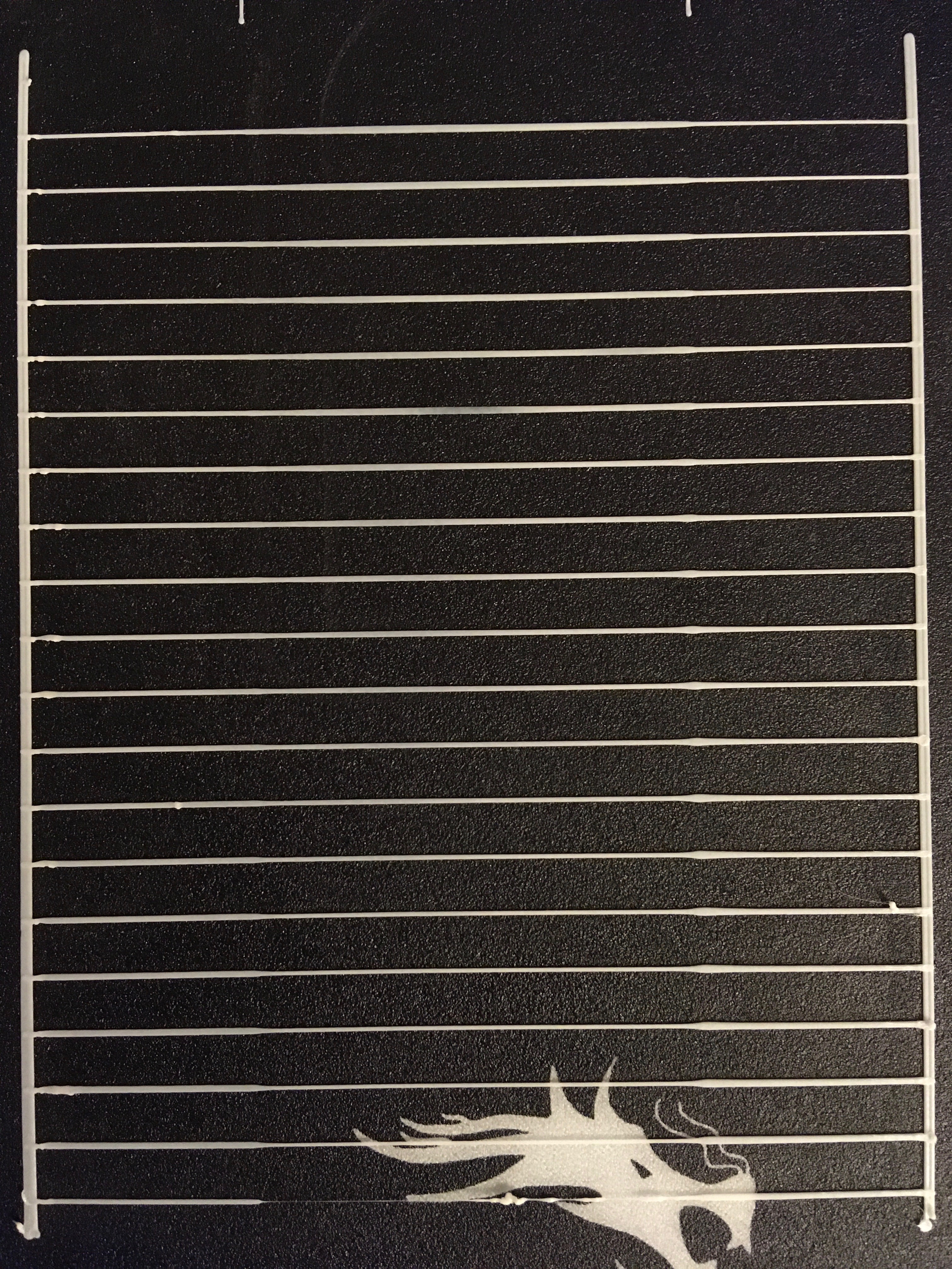
And what I got so far:
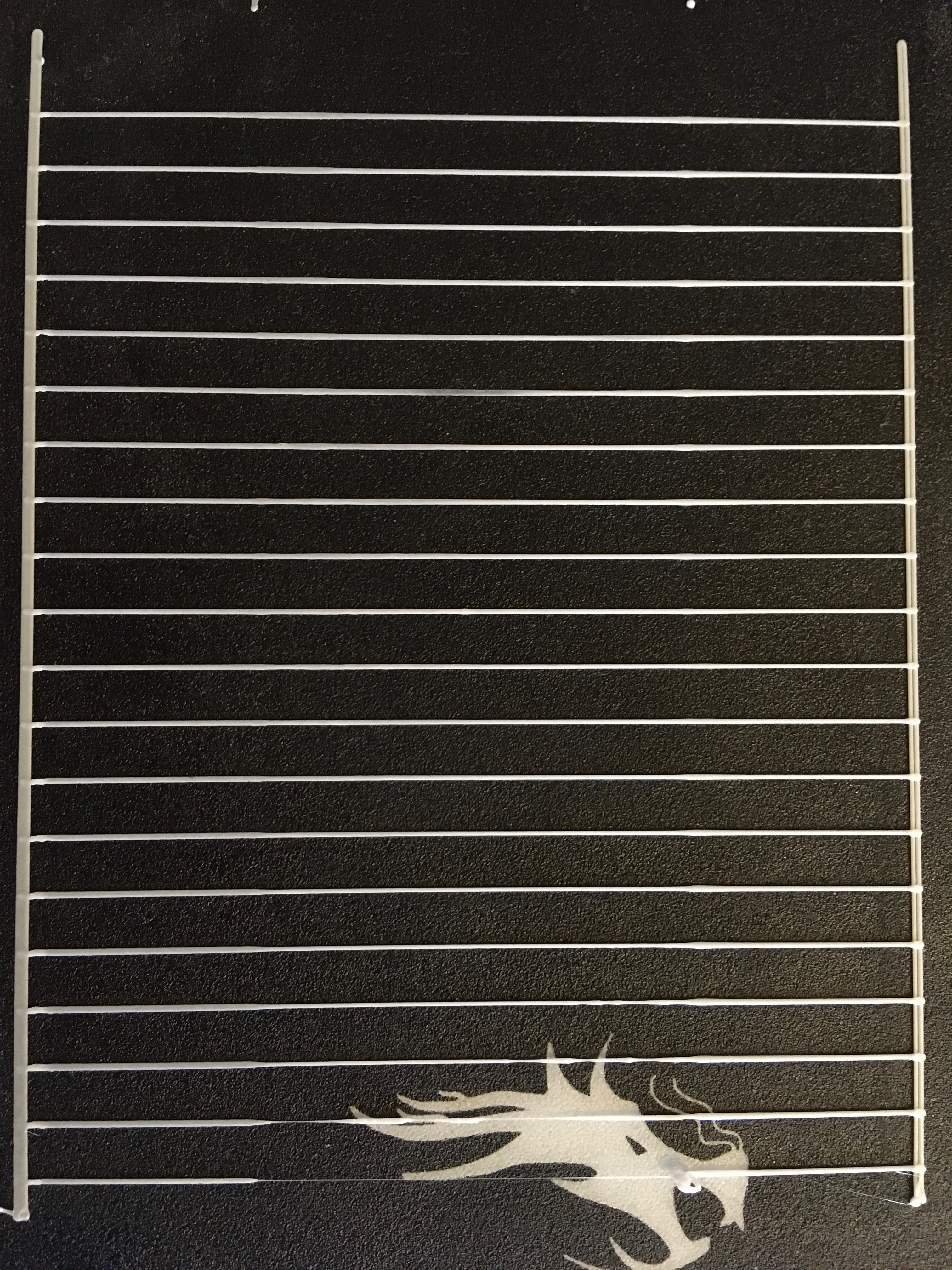
K from 0 to 2, step 0.1. Line with K=0.9 looks perfect :)
So, for me it proves the need of second, independent K that will affect how far final_adv_steps of current block will go beyond max_adv_steps of next block. And definitely it must count back to max_adv_steps in next block to avoid this:
Any thoughts?
sbasmanov
on 31 May 2020
I did more different tests and now I see three ways to fight with bulge :)
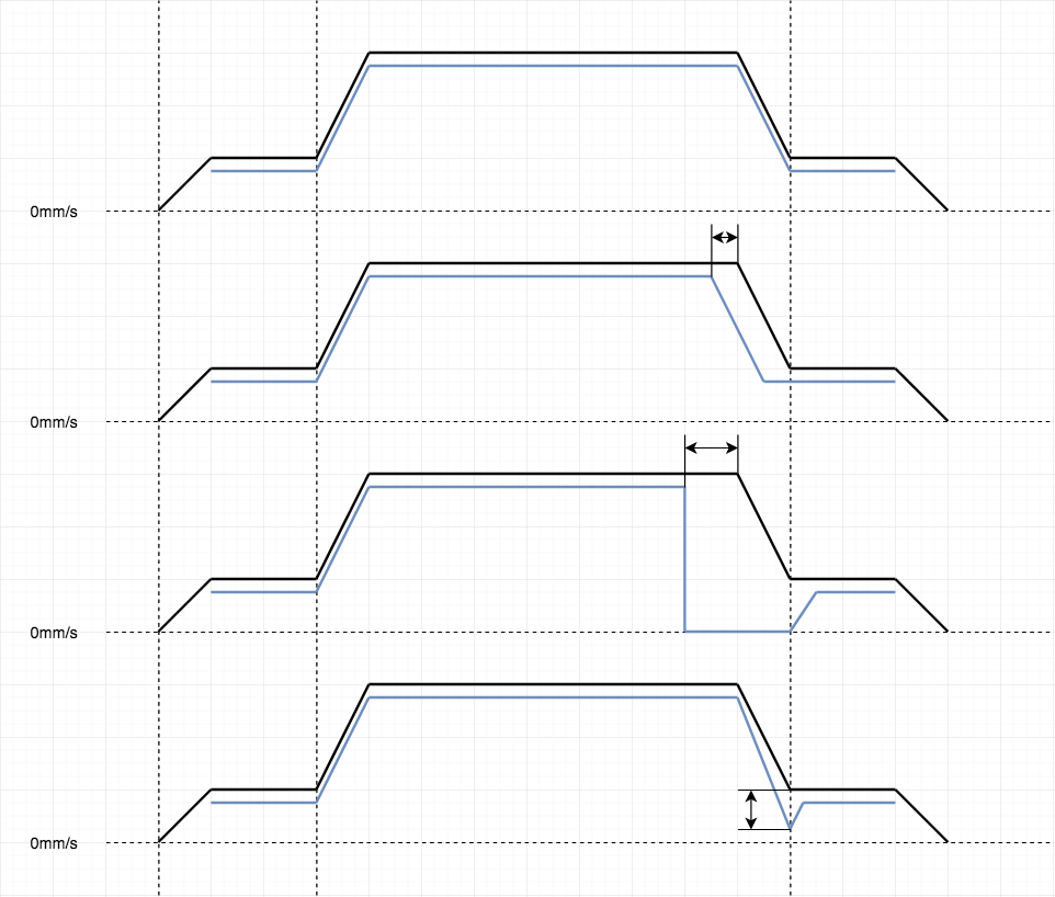
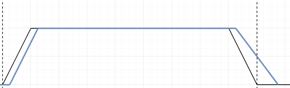
So, graphs - black line is axis speed, blue line is E speed. Not real, just for illustration.
- This is how LA works right now. Adding more E pulses on acceleration and more -E (reverse) on deceleration. Same amount, symmetry.
- We can try start LA decompression (issuing -E pulses) slightly before axis deceleration. May be this will work.
- We can completely stop E before axis deceleration, so no retraction will be made at all. This (partially) works for straight lines, but needs precise calculation.
- This is what I tried to test with lower final_adv_steps and it somehow works, but I'm not sure about corners and chained segments with same speed. Needs more testing.
So, may be somebody else have other ideas? May be I missing something?
But in any case I think we need to rewrite LA code first, to split acceleration & deceleration parts completely, so they can be adjusted independently.
sbasmanov
on 31 May 2020
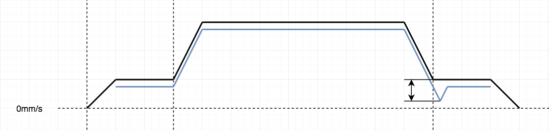
Very nice. There's certainly many other possibilities, but one I already thought about is the following (sorry, no nice graphs 😄 ):
- Reduce LA steps like in original LA (your 1.), but keep reducing into the slow segment. Then, there could be a short hold period, where LA setps are kept constant. This is optional and maybe useless. Afterwards, we allow LA to increase steps to the default again. This would look similar to your 4., but the lowpoint of LA steps would be a bit inside the last slow segment.
I think this (5.) will be very effective against the bulge. But I didn't have the time to test, yet. It would be very cool if you could check that, too. Otherwise, I will see if I get to it next week.
I also think that all methods, where we change LA setps earlier or later than LA does now will be tricky to implement in a robust way. Especially on very short segments, things will begin to overlap and we have to decide which logic (i.e. original LA increasing steps, where we would already decrease) has higher priority.
XDA-Bam
on 31 May 2020
Well, to implement this logic (5) we have to add extra isr code that will detect, should it do normal acceleration/cruise or continue retract. This looks very complex, so this is why I tried to stay within single block. But why not to try (5). Anyway, this will require additional K and completely rewrite LA code. So, I’ll try to make a test in next few days and post results here.
Oh, nice graph :)
sbasmanov
on 1 Jun 2020
Oh, nice graph :)
Indeed 👍
It may not require "total rewrite". Might be enough to define an offset LA_offset_steps, which is calculated only if the block has a deceleration phase (zero otherwise). The offset is then substracted from LA_final_adv_steps and LA_max_adv_steps (which are identical for the problematic case) to set our new, lower target for LA_current_adv_steps. As soon as LA_current_adv_steps reaches this target, the offset is reset to zero, which causes the steps to increase again.
If it works like this, it's not gonna too complex. But I may have overlooked some potential pitfalls.
XDA-Bam
on 1 Jun 2020
which is calculated only if the block has a deceleration phase (zero otherwise).
Not only. Don't forget about corners, when two blocks with same speed, but different direction. I see that the only case when we don't need this compensation - when next block have higher speed. Probably we could add condition in advance_isr() if this offset is not zero, it will decrement LA_steps. Otherwise regular logic will work. Ok, I'll try this.
sbasmanov
on 1 Jun 2020
Here is code:
https://github.com/MarlinFirmware/Marlin/blob/e4d8336175ee09b28d23220f446d07451ca3de43/Marlin/src/module/planner.cpp#L1143
            #if ENABLED(LIN_ADVANCE)
              if (block->use_advance_lead) {
                const float comp = block->e_D_ratio * extruder_advance_K[active_extruder] * settings.axis_steps_per_mm[E_AXIS];
                block->max_adv_steps = current_nominal_speed * comp;
                block->final_adv_steps = next_entry_speed * comp;
                if(current_nominal_speed >= next_entry_speed) {
                  block->advance_offset = next_entry_speed * (extruder_advance_K[active_extruder] < 1 ? extruder_advance_K[active_extruder] : 1);
                } else {
                  block->advance_offset = 0;
                }
              }
            #endif
Used same K just because don't have another K in M900 yet. Just multiply next_entry_speed by K, while it 0 < K < 1. Not sure if this is correct way, but will go for test.
https://github.com/MarlinFirmware/Marlin/blob/e4d8336175ee09b28d23220f446d07451ca3de43/Marlin/src/module/stepper.cpp#L1735
        #if ENABLED(LIN_ADVANCE)
          if (LA_use_advance_lead) {
            // Wake up eISR on first deceleration loop and fire ISR if final adv_rate is reached
            if (step_events_completed <= decelerate_after + steps_per_isr || (LA_steps && LA_isr_rate != current_block->advance_speed)) {
              initiateLA();
              LA_isr_rate = current_block->advance_speed;
              LA_offset_steps = current_block->advance_offset;
            }
          }
          else if (LA_steps) initiateLA();
        #endif
    if (LA_use_advance_lead) {
      if (step_events_completed > decelerate_after && LA_current_adv_steps > LA_final_adv_steps) {
        LA_steps--;
        LA_current_adv_steps--;
        interval = LA_isr_rate;
      }
      else if(LA_offset_steps > 0) {
        LA_offset_steps--;
        LA_steps--;
        LA_current_adv_steps--;
        interval = LA_isr_rate;
      }
      else if (step_events_completed < decelerate_after && LA_current_adv_steps < LA_max_adv_steps) {
             //step_events_completed <= (uint32_t)accelerate_until) {
        LA_steps++;
        LA_current_adv_steps++;
        interval = LA_isr_rate;
      }
      else
        interval = LA_isr_rate = LA_ADV_NEVER;
    }
    else
      interval = LA_ADV_NEVER;
And result
So if I didn’t make any mistakes in code, seems it affects bulge with K close to 1.
sbasmanov
on 1 Jun 2020
And this is with
block->advance_offset = next_entry_speed;
-E steps being accumulated, so there is no filament at all :)
sbasmanov
on 1 Jun 2020
OK, I also found the time to test this. I implemented it a little bit differently. After line
https://github.com/MarlinFirmware/Marlin/blob/6c994002af1ef13004490b5e15501e6cdc70dd88/Marlin/src/module/planner.cpp#L1182
I added
if(next_entry_speed < current_nominal_speed)
  block->advance_offset = block->final_adv_steps * 0.25f;
else
  block->advance_offset = 0;
Thereby, the offset is always a fraction of final_adv_steps. Allowable range is [0,1]. For this test, K is the same for accel and decel. But effectively, this offset is the equivalent of a smaller K for deceleration. In stepper.cpp I then extended
https://github.com/MarlinFirmware/Marlin/blob/6c994002af1ef13004490b5e15501e6cdc70dd88/Marlin/src/module/stepper.cpp#L1917
by
LA_offset_steps = current_block->advance_offset;
just like you did. But the main stepping logic at
https://github.com/MarlinFirmware/Marlin/blob/6c994002af1ef13004490b5e15501e6cdc70dd88/Marlin/src/module/stepper.cpp#L2267
looks a bit different:
if (step_events_completed > decelerate_after && LA_current_adv_steps > LA_final_adv_steps - LA_offset_steps) {
  LA_steps--;
  LA_current_adv_steps--;
  interval = LA_isr_rate;
}
else if (step_events_completed < decelerate_after && LA_offset_steps > 0) {
  LA_steps--;
  LA_current_adv_steps--;
  LA_offset_steps--;
  interval = LA_isr_rate;
}
else if (step_events_completed < decelerate_after && LA_current_adv_steps < LA_max_adv_steps) {
...
Basically, it allows the advance steps to already be less than LA_final_adv_steps in the fast segment, but this does not come into play unless LA_isr_rate is modified. With this setup, results for an offset factor of 0.25f look like this:
That looks okay-ish, but the slow segment is a bit on the thin side. Also, there seems to be some effect during the acceleration phase of the fast segment. I don't understand how that could happen, because the offset shouldn't affect it.
Ignoring this problem, I then went on to tinker with LA_isr_rate like you did in your version (1.). I changed
https://github.com/MarlinFirmware/Marlin/blob/6c994002af1ef13004490b5e15501e6cdc70dd88/Marlin/src/module/stepper.cpp#L1917
to
LA_isr_rate = (int) (current_block->advance_speed * 0.9f);
and lowered my offset factor to 0.20f. That means that LA_current_adv_steps < LA_final_adv_steps should already be reached slightly before the end of the fast segment. It should continue to go lower a couple steps into the slow segment and then rise again. The result looks like this:
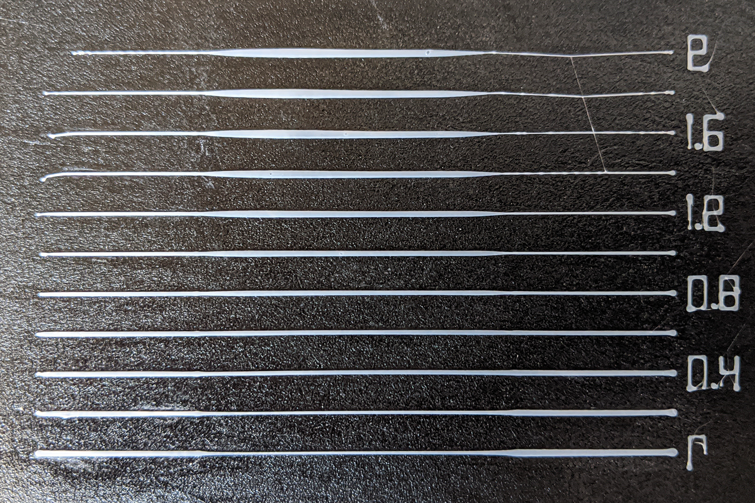
I'd say that is pretty damn good for K around 0.6. With a tiny bit more tuning, maybe an LA_isr_rate factor of 0.93f or something and an offset factor of 0.22f it's probably bang on.
I'm pretty optimistic about this solution. It kinda combines the best of two worlds: Your approach (1.) and my offset 😄 It needs two factors to work instead of one, so it will be harder to tune. But the results look very promising. You should try it! 👍
XDA-Bam
on 1 Jun 2020
Yeah, this looks good. Meanwhile, I added second K to parser, so we can run scripts with different settings, instead of hardcoding them. Not storing into EEPROM but enough for tests.
Here is diff. Sorry, just put changed files to single folder, because in work folder I touched many files, so no extra garbage will go to diff. This is from 2.0.x, but I think will apply to bugfix with some fuzz.
M900.diff.zip
I'll try your code later today.
sbasmanov
on 1 Jun 2020
if (step_events_completed > decelerate_after && LA_current_adv_steps > LA_final_adv_steps - LA_offset_steps) {
this is same as if you do block->final_adv_steps-=offset in planner but little more expensive. And yes, timer have to be adjusted. I just calculated it dumb way:
block->decomp_isr_K = (block->max_adv_steps - block->final_adv_steps) / (block->max_adv_steps - block->final_adv_steps * extruder_advance_Kd[active_extruder]);
I don't know how, but seems this
else if (step_events_completed < decelerate_after && LA_offset_steps > 0) {
may affect fast block. Needs investigation. In my code the idea was that first if() will do its usual work for normal deceleration, second else if(LA_offset_steps > 0) will start working after first finished (step_events_completed > decelerate_after && LA_current_adv_steps > LA_final_adv_steps is not true anymore) and after LA_offset_steps will go down to zero, third if() start adding E steps. So, by adding final_adv_steps-offset in first condition, together with adjusting timer, you just implemented (4). So, I tried combining 4 & 5 like this:
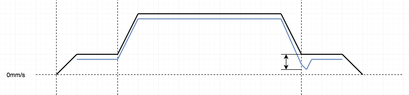
And it was retracting very hard, so after few lines it stopped feeding filament at all :) Probably I messed with K somewhere and this is why I got this result. I will review my calculations and try again.
sbasmanov
on 1 Jun 2020
I don't know how, but seems this
else if (step_events_completed < decelerate_after && LA_offset_steps > 0) {
may affect fast block.
Yeah, could be. I thought that LA_offset_steps should still be zero from the first block and would only change during the second once
LA_offset_steps = current_block->advance_offset;
is run, but maybe there's something I'm overlooking. We could probably define something like block->previous_did_decelerate in the planner, copy to LA_previous_did_decelerate in the stepper and then add to the check:
else if (step_events_completed < decelerate_after && LA_offset_steps > 0 && LA_previous_did_decelerate) {
We could probably define something like block->previous_did_decelerate in the planner, copy to LA_previous_did_decelerate in the stepper and then add to the check
This is overkill :) Look at original conditions: first always evaluated to true when decelerating. After deceleration finished, second condition start evaluating to true on acceleration. All we have to do is put our if(LA_offset_steps > 0) in the middle. This way it will always evaluate to true if we're not decelerating and there is some steps left. And because we add offset only if(current_nominal_speed >= next_entry_speed) this will never affect acceleration of next block.
sbasmanov
on 1 Jun 2020
So, I think we can try this calculations in planner:
                block->max_adv_steps = current_nominal_speed * comp;
                block->final_adv_steps = next_entry_speed * comp;
                if(current_nominal_speed >= next_entry_speed) {
                  block->final_adv_steps -= block->final_adv_steps * extruder_advance_Kd[active_extruder];
                  block->decomp_isr_K = (block->max_adv_steps - next_entry_speed * comp) / (block->max_adv_steps - block->final_adv_steps);
                  block->advance_offset = next_entry_speed * comp * extruder_advance_Kd[active_extruder];;
                } else {
                  block->advance_offset = 0;
                  block->decomp_isr_K = 1;
                }
First, we decreasing final_adv_steps with Kd growing, while adding advance_offset as well. So, finally it will go to new final_adv_steps (which is lower than original) and then will count offset steps also (on beginning of next block).
sbasmanov
on 1 Jun 2020
This is overkill :) Look at original conditions: first always evaluated to true when decelerating.
Maybe.
After deceleration finished, second condition start evaluating to true on acceleration. All we have to do is put our if(LA_offset_steps > 0) in the middle. This way it will always evaluate to true if we're not decelerating and there is some steps left. And because we add offset only if(current_nominal_speed >= next_entry_speed) this will never affect acceleration of next block.
I think I'm basically doing that right now - but I'll wait for your solution. If it works as expected, I'll not invest the time to debug my hacky code 😄
Concerning your new solution:
block->decomp_isr_K = (block->max_adv_steps - next_entry_speed * comp) / (block->max_adv_steps - block->final_adv_steps);
This risks a divide by zero, in case the block ends cruising and thereby max_adv_steps == final_adv_steps. Not relevant for test pattern, but will occur in practice. You could check for equality, or seperate into
if(current_nominal_speed > next_entry_speed){
...
} else if(current_nominal_speed == next_entry_speed) {
...
} else ...
So, I did test with K=0.9 and 0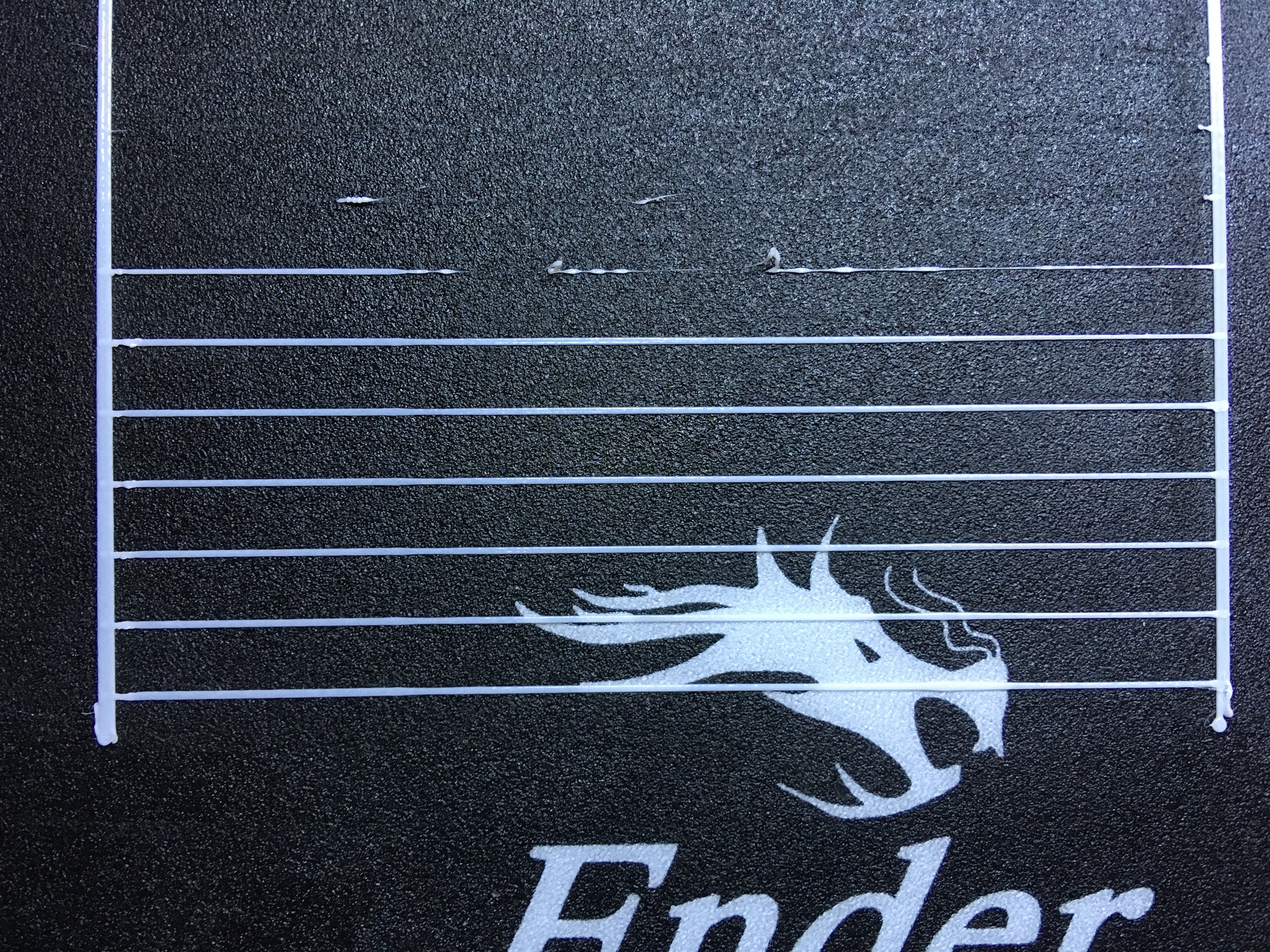
Way too much :) Extruder start clicking on retract after third line. But line with D=0.15 and D=0.2 looks good :)
his risks a divide by zero, in case the block ends cruising and thereby max_adv_steps == final_adv_steps. Not relevant for test pattern, but will occur in practice.
Yes, absolutely possible. This is very expensive math, should be changed to something more faster. Probably new timer interval can be calculated much easier way :) I just didn't look at this yet.
Adding diff with 2.0.x, run from src.
LA.diff.zip
sbasmanov
on 1 Jun 2020
Way too much :) Extruder start clicking on retract after third line. But line with D=0.15 and D=0.2 looks good :)
There's also that underextrusion at the beginning of the fast segment. Looks like it's also reducing steps, there.
XDA-Bam
on 1 Jun 2020
There's also that underextrusion at the beginning of the fast segment. Looks like it's also reducing steps, there.
Probably because of K=0.9, may be I need higher value. This underextrusion exists on first line, where D=0.
sbasmanov
on 1 Jun 2020
Ok, seems I have more or less, but stable result:
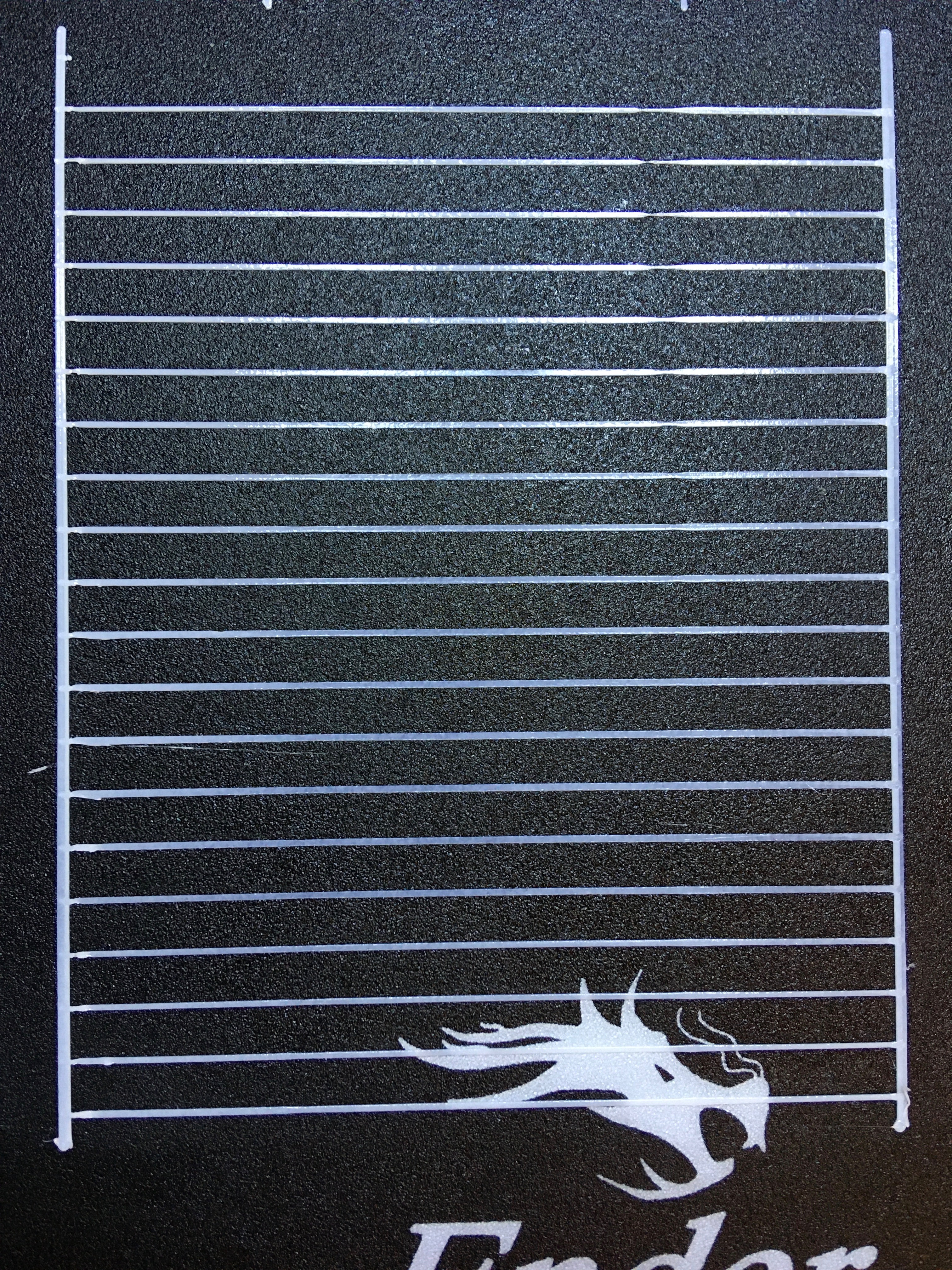
Idea is simple, still graph (4). I just took your idea how to change final_adv_steps :)
So, here is main changes in planner:
                block->max_adv_steps = current_nominal_speed * comp;
                block->final_adv_steps = next_entry_speed * comp;
                block->final_adv_steps -= block->final_adv_steps * extruder_advance_Kd[active_extruder];
and
      block->advance_speed = block->decomp_speed = (STEPPER_TIMER_RATE) / (extruder_advance_K[active_extruder] * block->e_D_ratio * block->acceleration * settings.axis_steps_per_mm[E_AXIS_N(extruder)]);
      block->decomp_speed -= block->advance_speed * extruder_advance_Kd[active_extruder];
Accordingly, in stepper:
            if (step_events_completed <= decelerate_after + steps_per_isr || (LA_steps && LA_isr_rate != current_block->decomp_speed)) {
              initiateLA();
              LA_isr_rate = current_block->decomp_speed;
All this produce very extreme values with D close to 1:
advance_speed:1048 decomp_speed:52
comp:3.43 max_advance_steps:274 final_adv_steps:12
Definitely, this math should be changed to something more safe. Having interval 52 (instead of 1048) is not good idea. But now I feel I'm on right way :) Only thing I can't do is this formulas. Would be really great, if somebody will help with this, to get proper calculations without -= and so on.
Or may be simply multiply by Kd ? Make it from 0.5 to 1. So:
block->final_adv_steps = next_entry_speed * comp * extruder_advance_Kd[active_extruder];
and
block->decomp_speed = block->advance_speed * extruder_advance_Kd[active_extruder];
When it 1 - no correction, when it 0.5 - maximum correction.
sbasmanov
on 2 Jun 2020
Ok, after re-leveling bed I realized that final_adv_steps alone don't fix bulge completely. So, I added offset back and here is result:
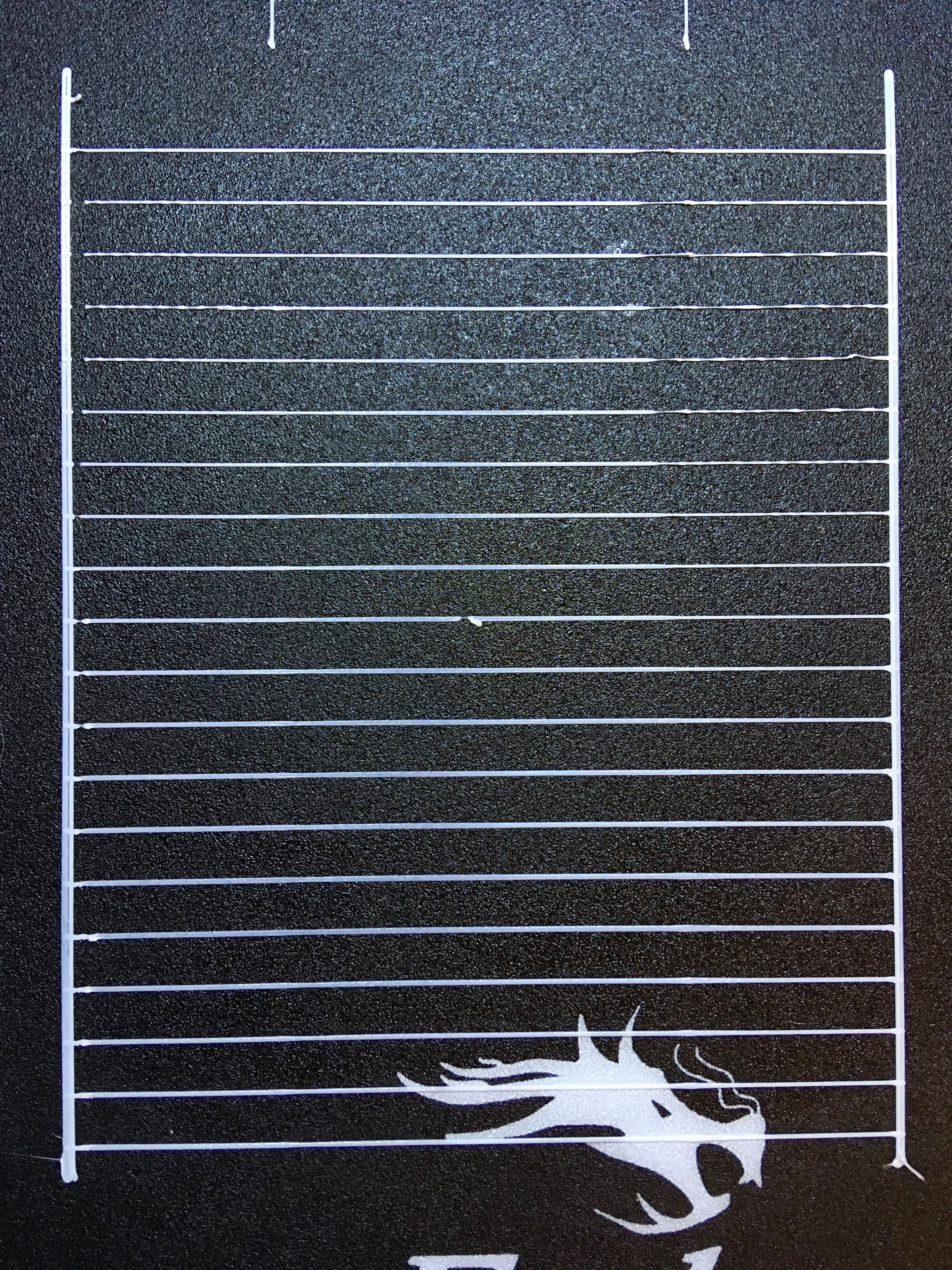
This looks much better :)
So, attached diff against 2.0.x and debug log. Debug points are commented out SERIAL_ECHOLNPAIR in stepper and planner. Tried to keep serial TX as short as possible, so this is why this abbreviations :)
Would be great, if somebody else try this on 2.0.x. Test consists of two parts:
- print normal LA test pattern from site, choose which K is good
- manually modify gcode with test pattern replacing M900 Kxxx with chosen K and adding D from 0 to 0.9. For example: M900 K0.9 D0.05 Warning! Never go higher than D=0.95.
LA_test.zip
ps: in zip my D test pattern for ender3 with D from 0 to 0.95. If all other settings is ok, just replace K0.9 with another value.
sbasmanov
on 2 Jun 2020
Both look good. But with the offset directly coupled to Kd, I think we're missing a second tuning parameter. On your current test pattern, there is either a small bit of the blob left, or the last slow segment is too thin. I also had that problem when the offset was too large.
I think we need to decouple the variable which speeds up the advance ISR to reduce steps faster from the variable which determines the number of offset steps. Those need to be two tunables.
XDA-Bam
on 2 Jun 2020
I think we need to decouple the variable which speeds up the advance ISR to reduce steps faster from the variable which determines the number of offset steps. Those need to be two tunables.
ISR interval for deceleration must be calculated from new final_adv_steps, so it will fire at proper intervals and decrement LA_curent_adv_steps to new final_adv_steps value. I mean it should not be calculated using Kd, but new steps amount instead. After this, Kd will affect only how low final_adv_steps will be and how much offset steps. So, this:
And this is where I have problems with math. I don't know how to calculate new interval properly (decomp_speed in my code).
sbasmanov
on 2 Jun 2020
Tried to print test cube. Even that test looks fine, real print goes nuts :) First, with K0.9 D0.3
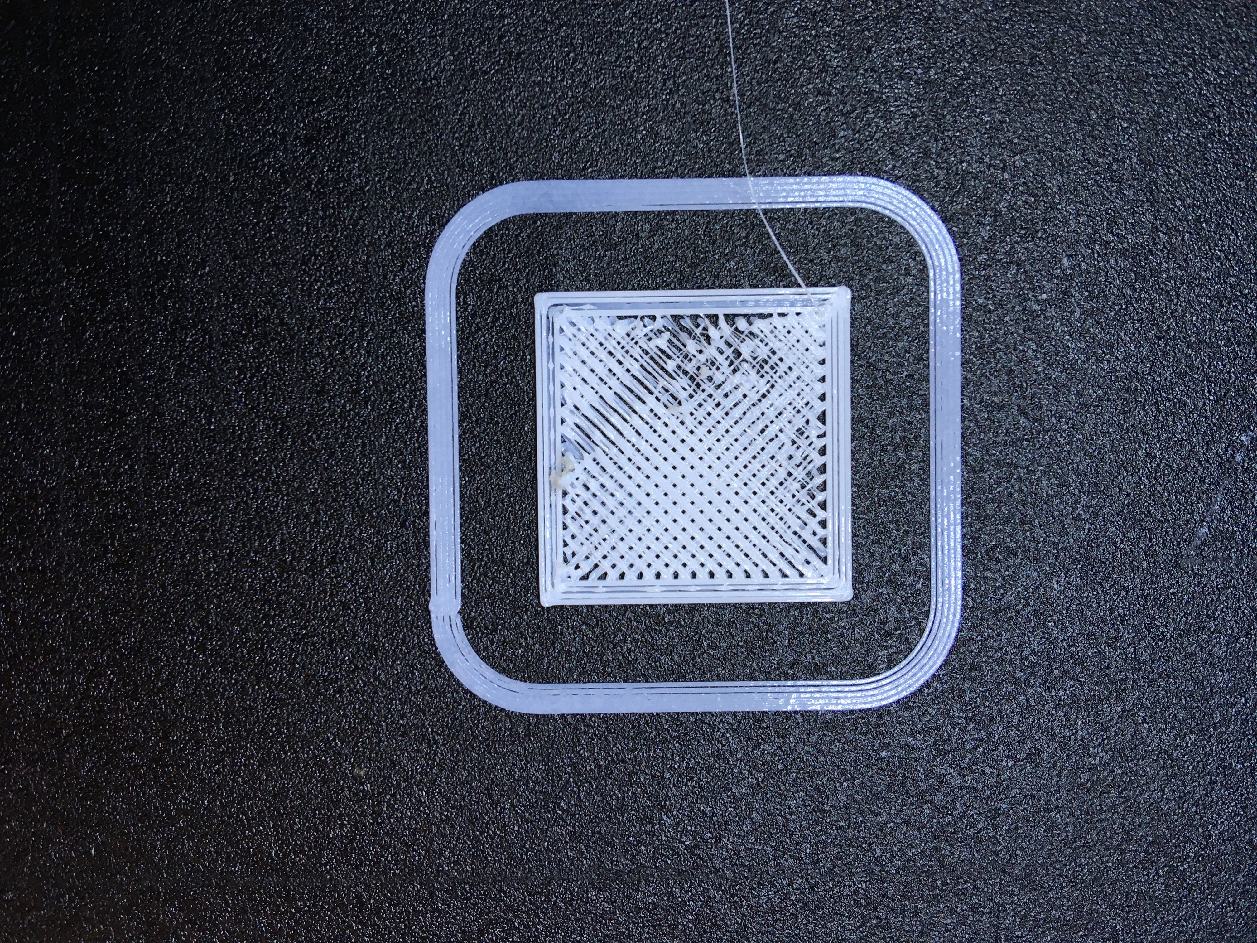
Strong underextrusions on short lines, gets better in middle. So, K0.9 D0.2:
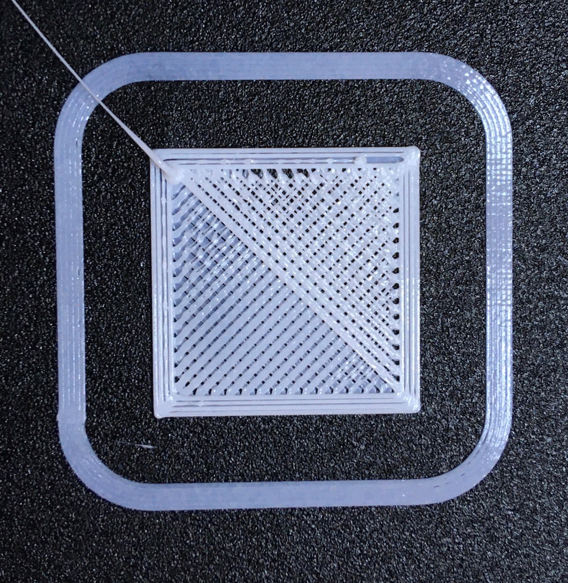
Little better, but still problems. Next K0.9 D0.1 Stopped after a while, to see what's inside.
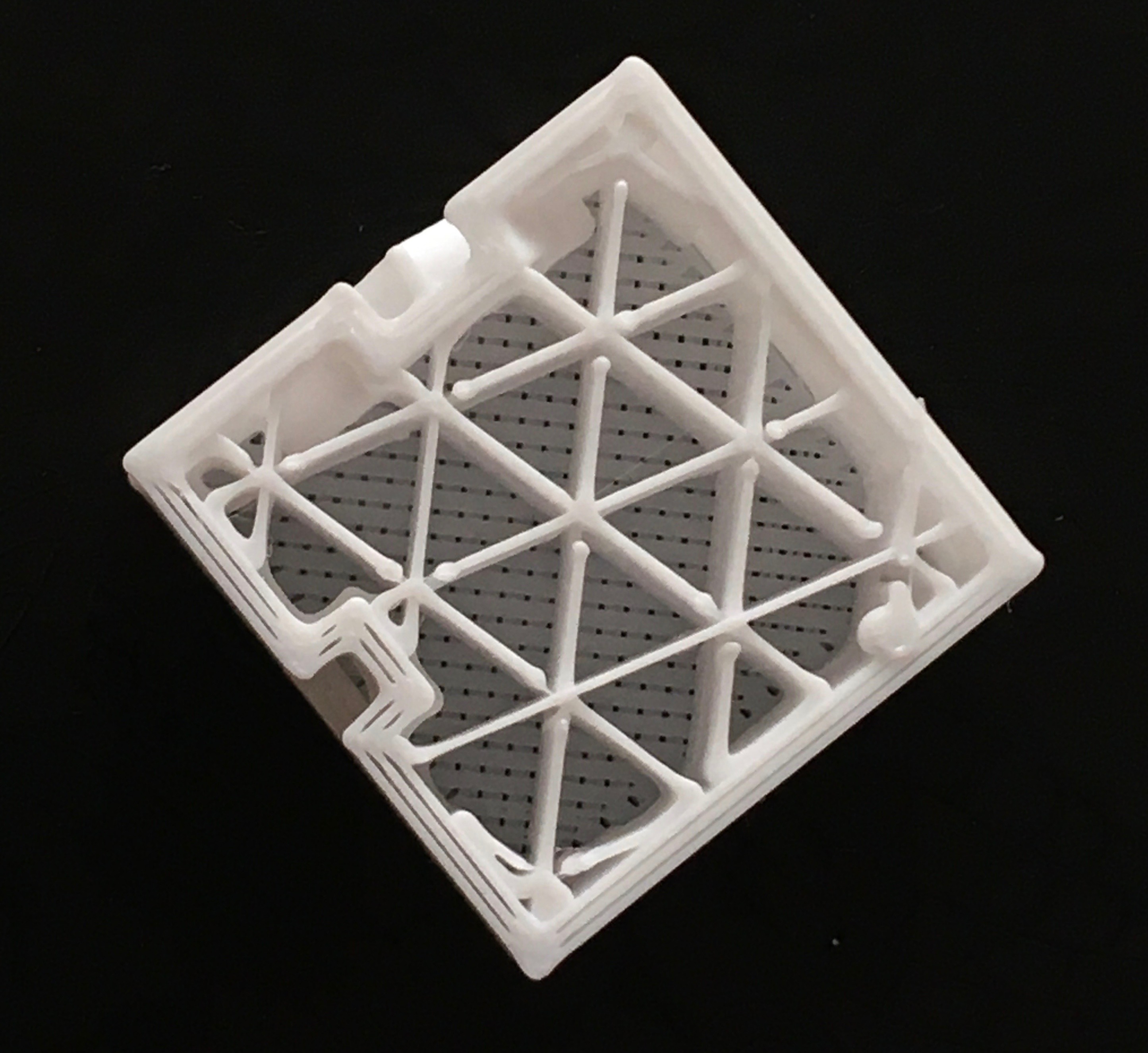
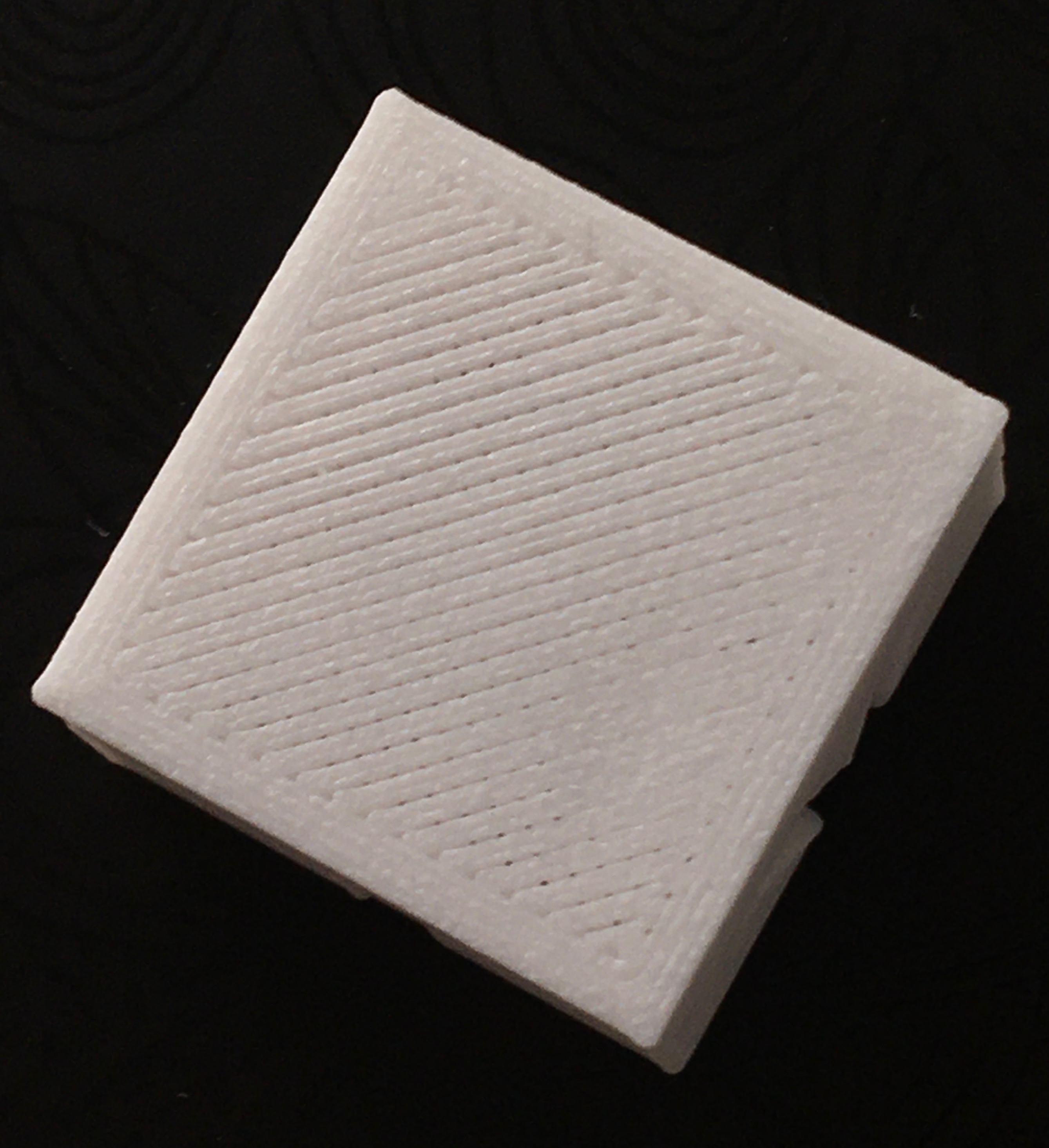
Strange line on X:
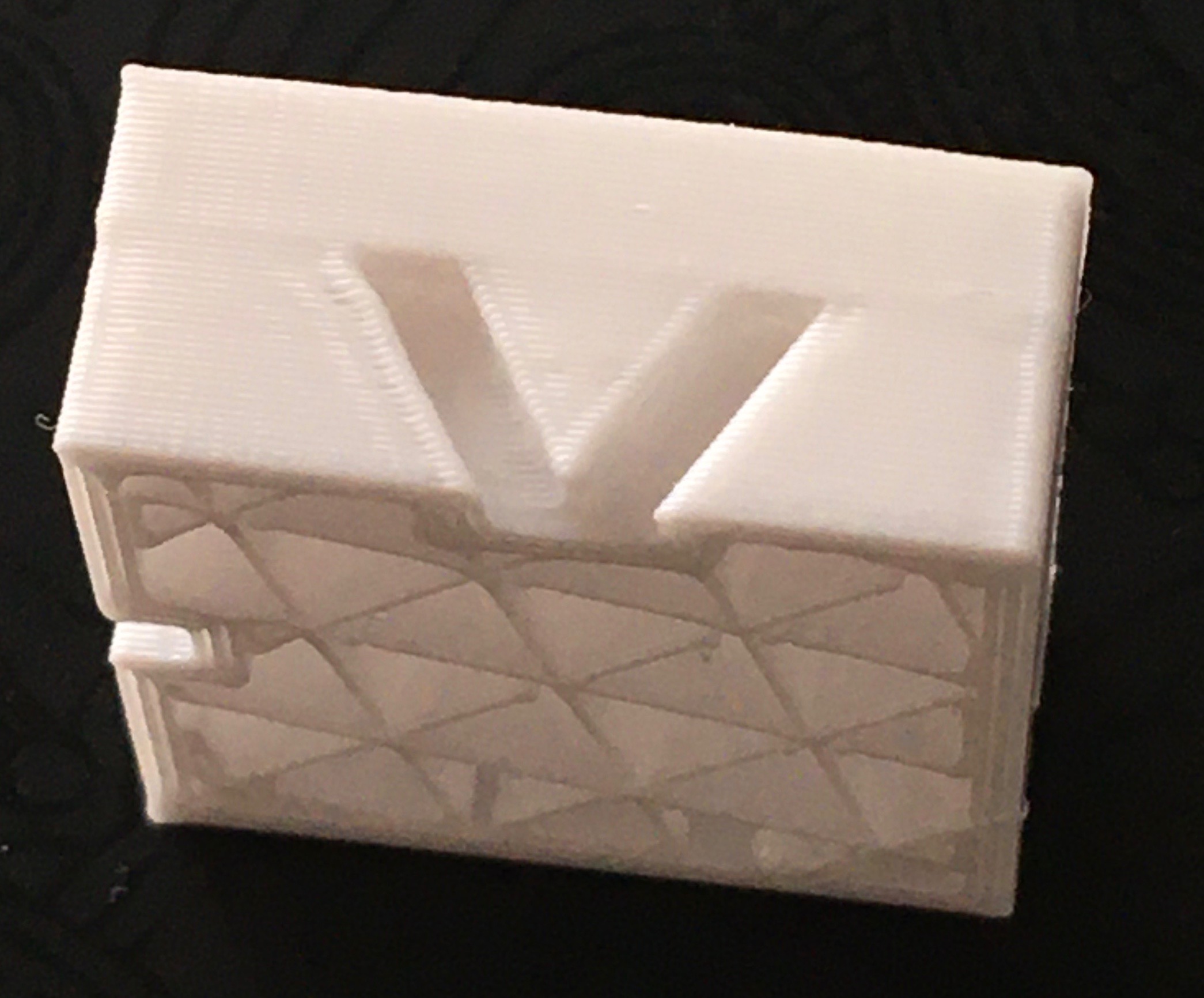
And geometry change when perimeter changed:
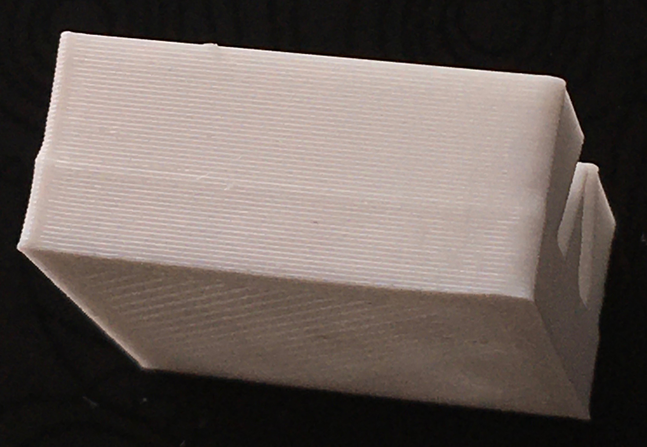
So, we have something to work with. First, timer interval must be calculated properly. Need help with this. Then we can play with Kd and offset and see how it works.
sbasmanov
on 2 Jun 2020
The strange line on the X happens to me with the original LA, so that's not new.
Edit: And it isn't an X, Y or Z binding on my part, because it doesn't show up on other prints.
@sbasmanov Or the gcode was fine with the old LA?
qwewer0
on 2 Jun 2020
So, we have something to work with. First, timer interval must be calculated properly. Need help with this. Then we can play with Kd and offset and see how it works.
I can take a look. What exactly is problematic with the timer? What`s your target interval?
XDA-Bam
on 2 Jun 2020
The strange line on the X happens to me with the original LA, so that's not new.
Edit: And it isn't an X, Y or Z binding on my part, because it doesn't show up on other prints.
@sbasmanov Or the gcode was fine with the old LA?
This is cube I printed this morning, after https://github.com/MarlinFirmware/Marlin/issues/16880#issuecomment-637186909
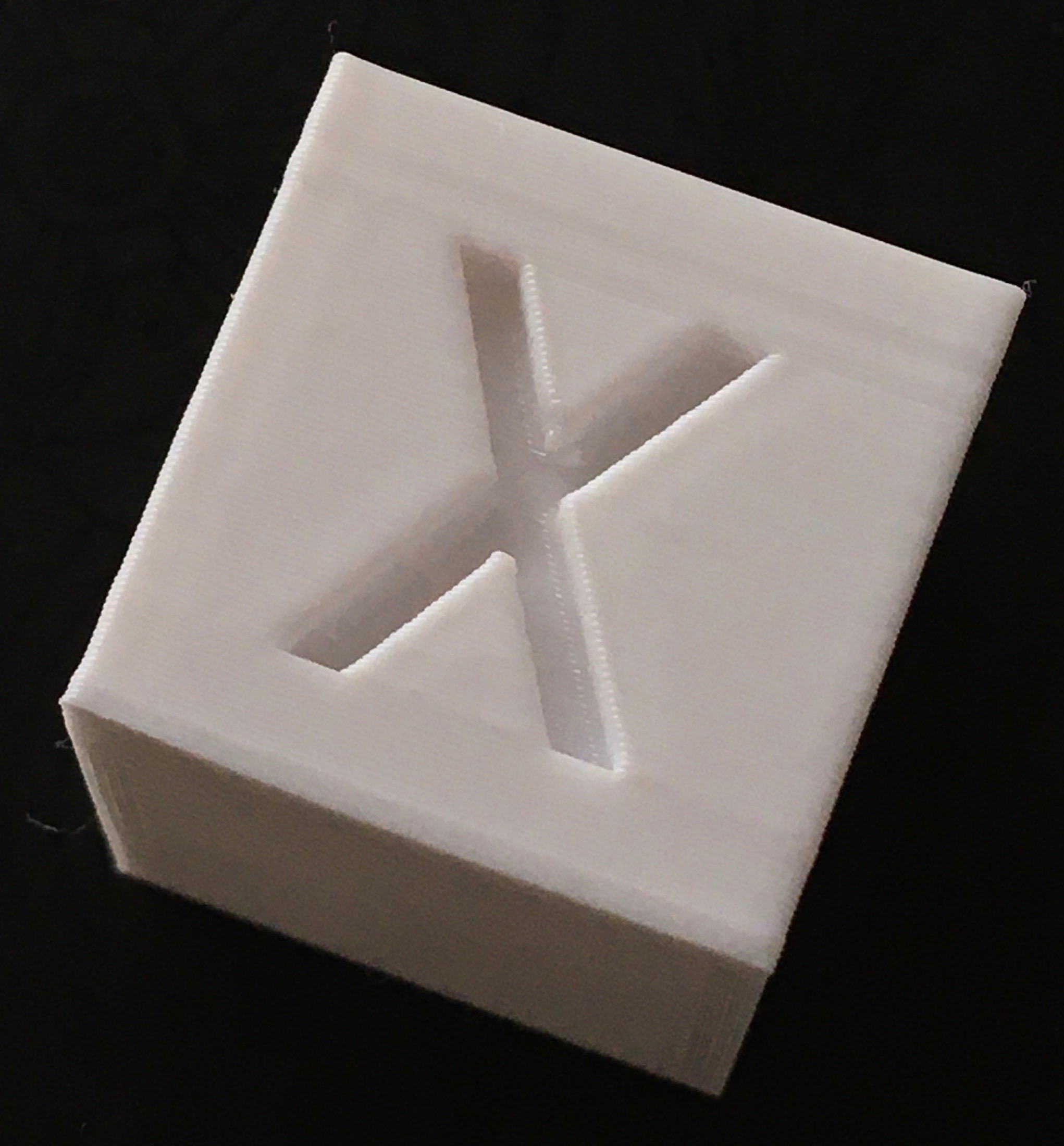
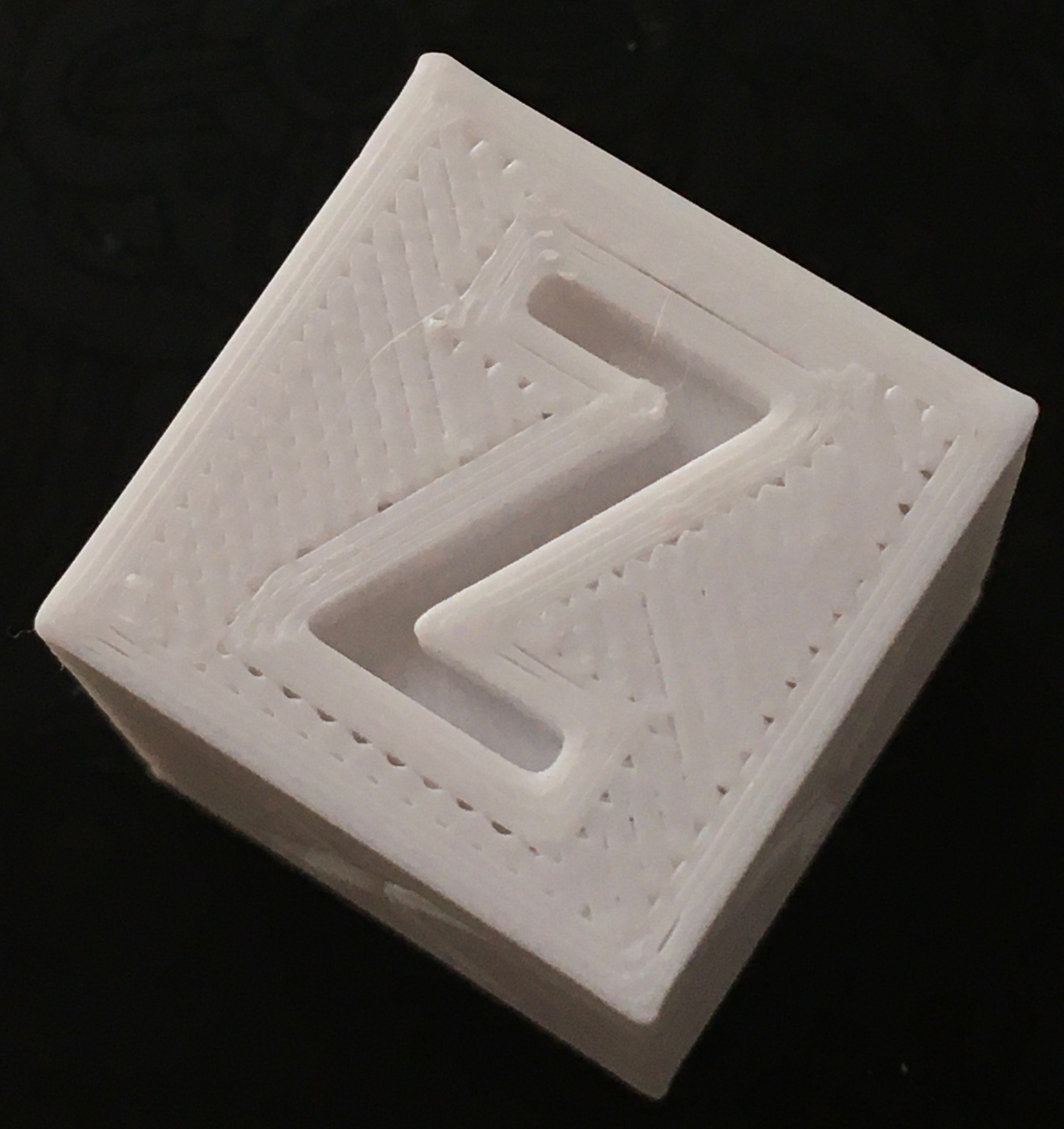
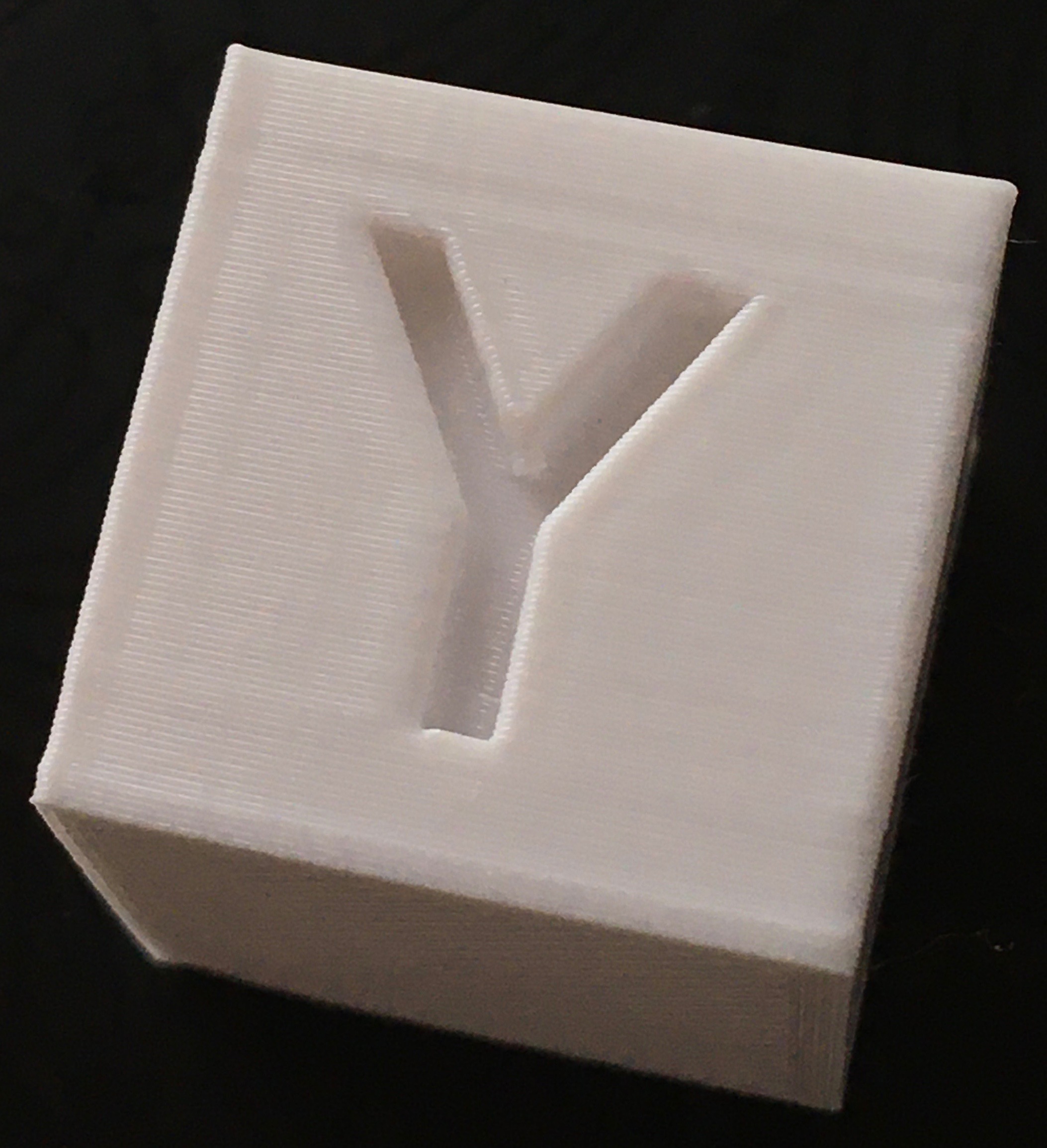
And this is what I have now, with K0.9 D0.1 and retraction in Cura reduced from 6.5 to 3.
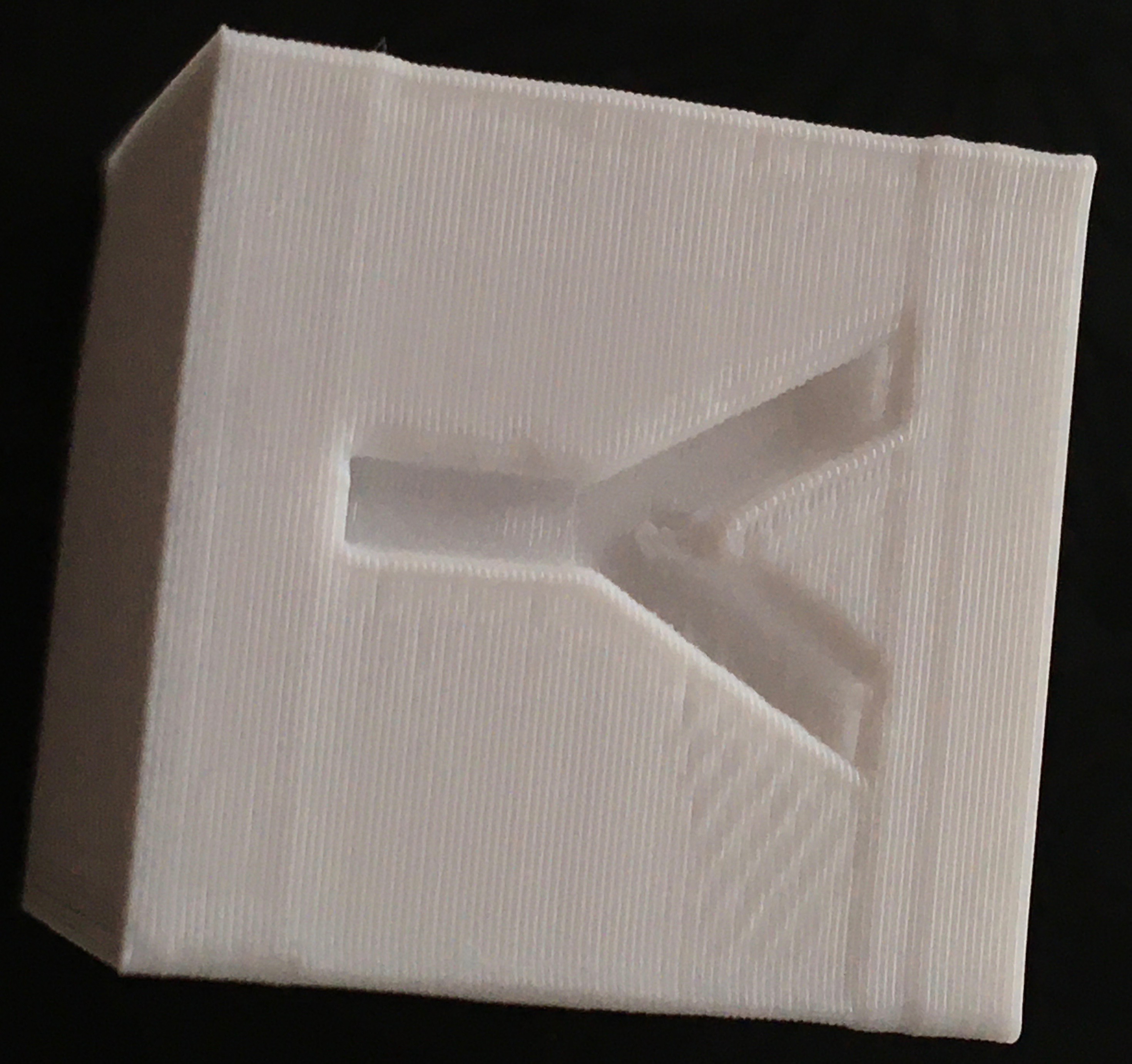
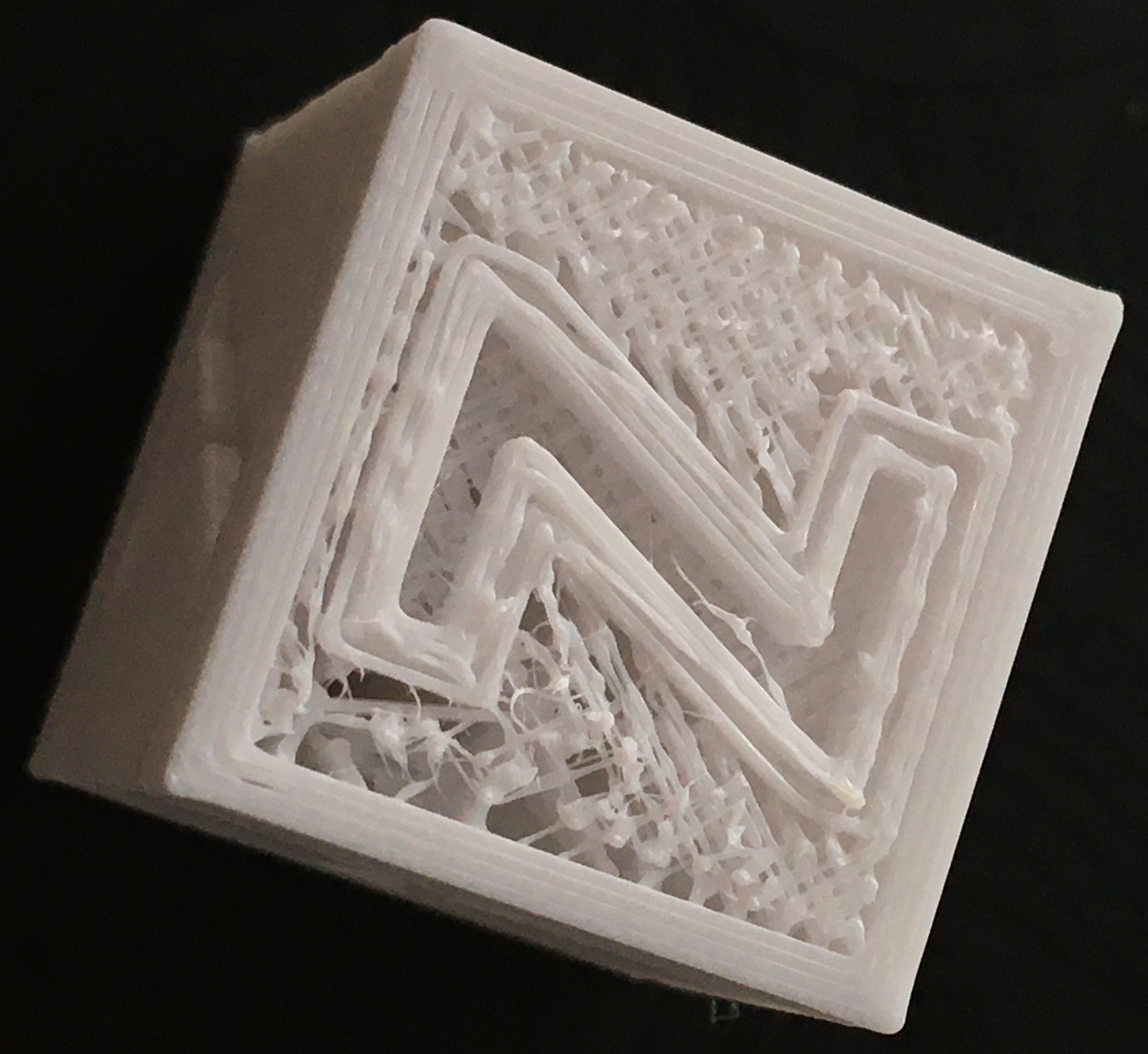
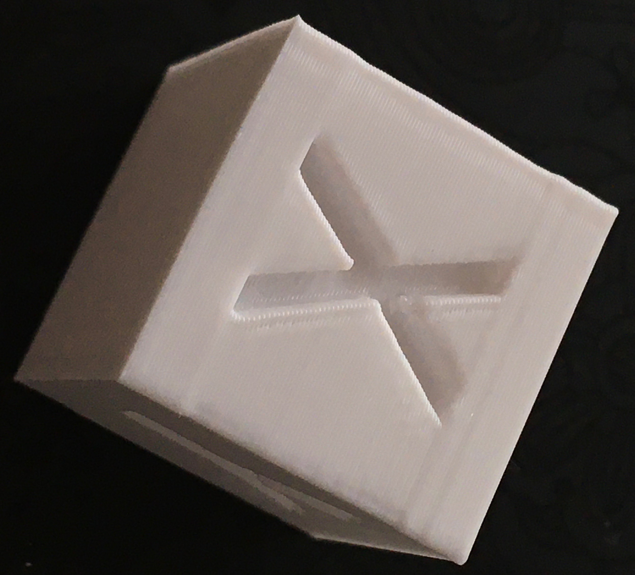
Feel the difference :)
So, seems I haven't seen this problem before.
I was watching how it prints and all lines after small areas filled with zig-zag was suffering from under extrusion. This is what you can see on top with Z - a lot small zig-zag pieces. Feels like retraction steps being accumulated somewhere, so it almost completely pulls filament out of nozzle.
sbasmanov
on 2 Jun 2020
I can take a look. What exactly is problematic with the timer? What`s your target interval?
Well, now it sets interval (block->advance_speed in planner) so it's more or less precisely counts steps from max_adv_steps down to final_adv_steps. If we change final_adv_steps to lower value, we need to make timer interval shorter, so it still count down to final_adv_steps (distance increased, more steps needed). And I feel there should be science way to do this, instead of extracting piece from advance_speed in proportion to Kd :)
sbasmanov
on 2 Jun 2020
I added third parameter to M900 - O :) for offset.
Test pattern with K0.9 D0.2 0 < O < 0.95 (hmm.. better change to something else :)
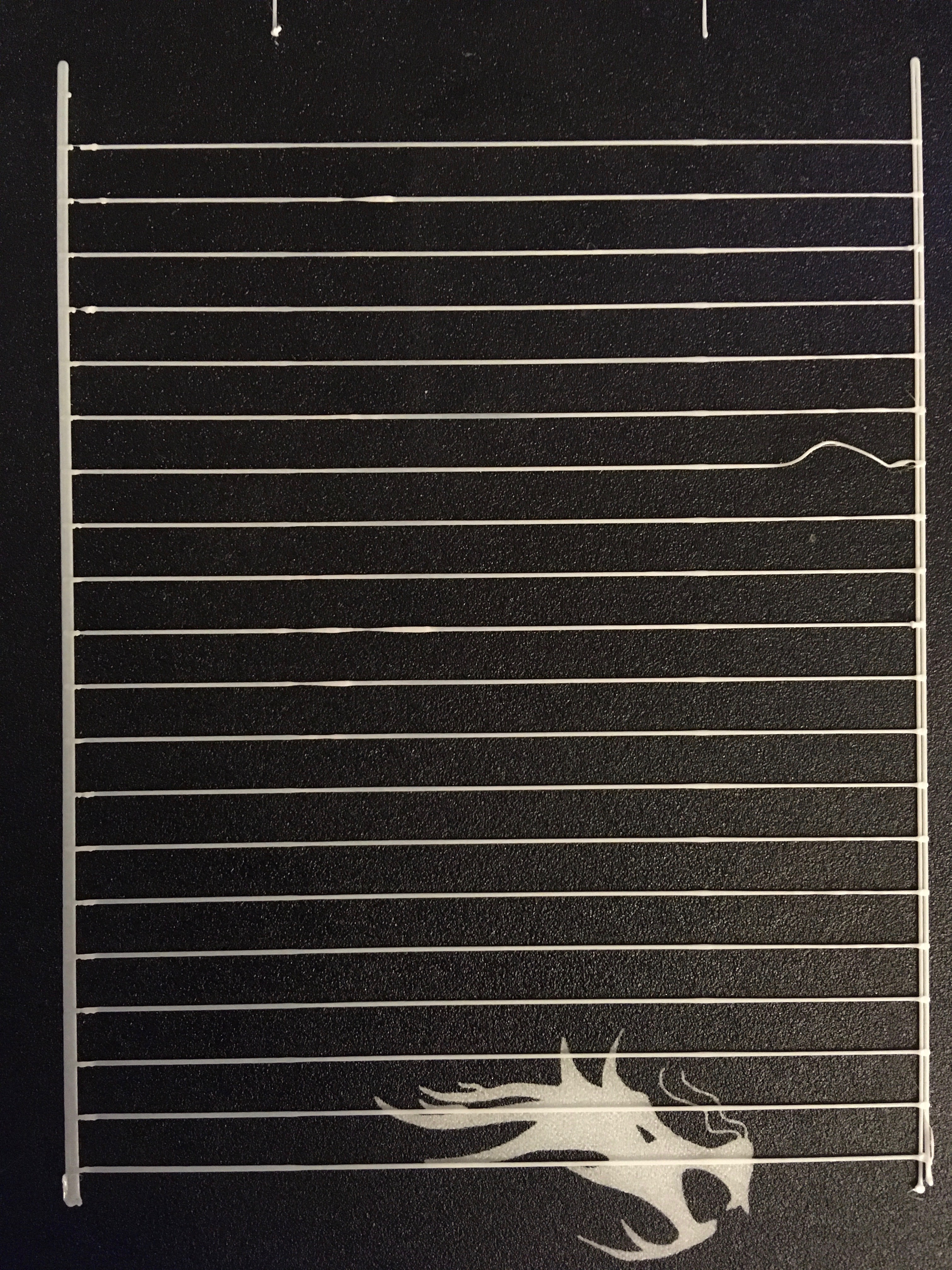
Same pattern, but K0.9 D0 and 0 < O < 0.95
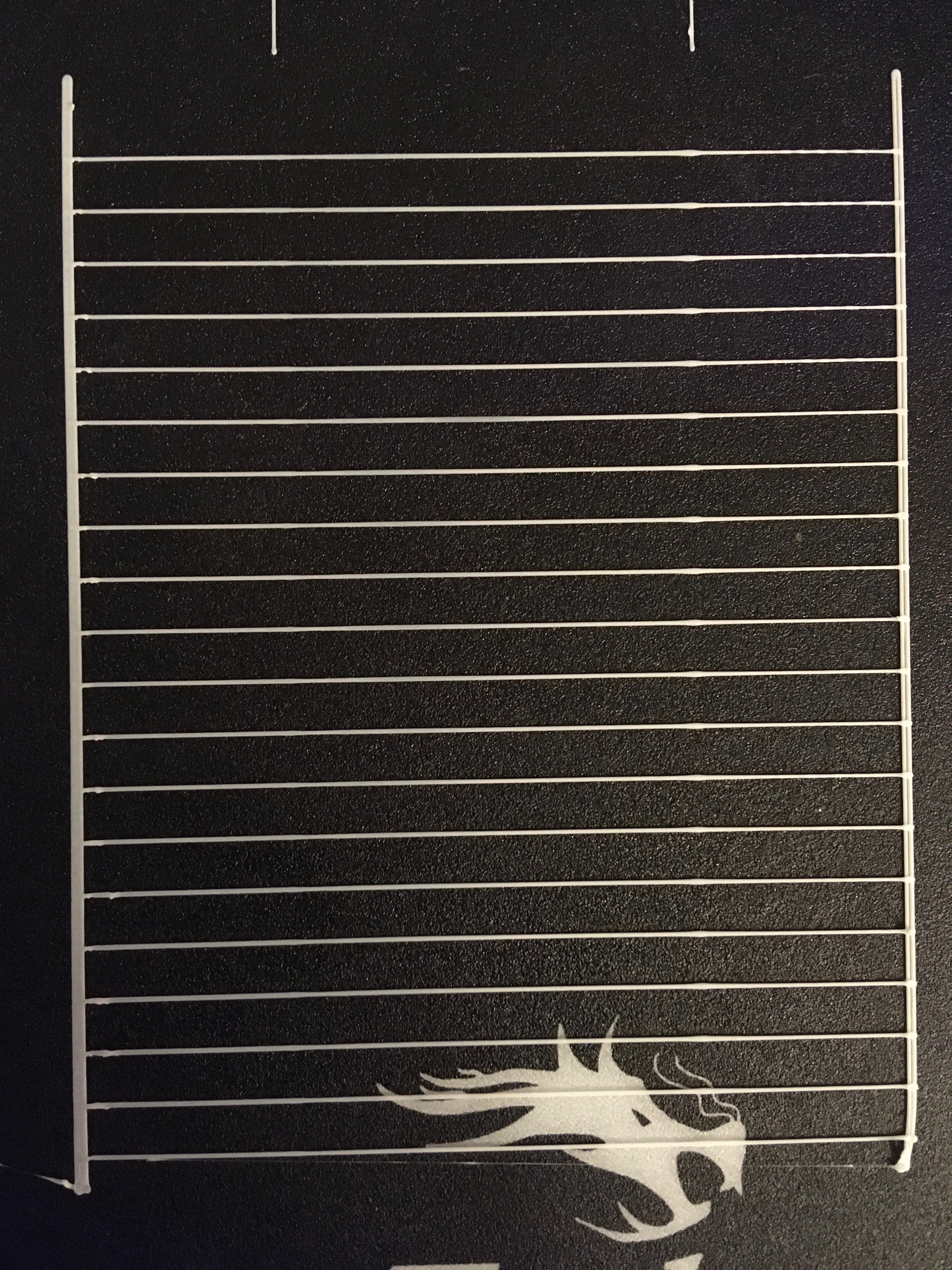
Diff:
LA.diff.zip
sbasmanov
on 2 Jun 2020
Your diff shows, that currently the following is done:
block->advance_speed = block->decomp_speed = (STEPPER_TIMER_RATE) / (extruder_advance_K[active_extruder] * block->e_D_ratio * block->acceleration * settings.axis_steps_per_mm[E_AXIS_N(extruder)]);
block->decomp_speed -= block->advance_speed * extruder_advance_Kd[active_extruder];
and
block->final_adv_steps = next_entry_speed * comp;
block->final_adv_steps -= block->final_adv_steps * extruder_advance_Kd[active_extruder];
if(current_nominal_speed >= next_entry_speed) {
  block->decomp_offset = block->final_adv_steps * extruder_advance_Kd[active_extruder];
} else {
  block->decomp_offset = 0;
}
If you want to reach LA_final_adv_steps at the end of the fast segment, you need to do
block->advance_speed = (STEPPER_TIMER_RATE) / (extruder_advance_K[active_extruder] * block->e_D_ratio * block->acceleration * settings.axis_steps_per_mm[E_AXIS_N(extruder)]);
block->decomp_speed = block->advance_speed * extruder_advance_K[active_extruder] / extruder_advance_Kd[active_extruder];
and
block->final_adv_steps = block->decomp_offset = next_entry_speed * comp; // decomp_offset  is used as temporary storage here
block->final_adv_steps = block->final_adv_steps * extruder_advance_Kd[active_extruder] / extruder_advance_K[active_extruder];
if(current_nominal_speed >= next_entry_speed) {
  block->decomp_offset -= block->final_adv_steps;
} else {
  block->decomp_offset = 0;
}
This works as intended for KdLA_current_adv_steps == LA_max_adv_steps - decomp_offset will be fullfilled and steps will increase immediately.
I hope that's what you're looking for. However, that's not what I intended with the offset: The idea was to reduce LA_current_adv_steps a bit faster, but not so fast that the lowpoint is reached in the fast segment. It should be a little bit into the second slow one.
XDA-Bam
on 2 Jun 2020
Okay, seems we have to split this into two pieces: deceleration and offset.
Deceleration: imagine that at deceleration point (fast block) we have values: max_adv_steps=100 and final_adv_steps=50. We decelerate within 1 second. This means, we have to fire 50 interrupts to decrement current_adv_steps by 50 steps. This will issue 50 negative pulses on E. Now, we change final_adv_steps=40. This means we have to fire 60 interrupts within same second to decrement current_adv_steps by 60 to issue 60 negative pulses on E. Timer should be adjusted by this change, so it will fire exactly (+/-) 60 interrupts. Next.
Offset: after fast block finished, we counting offset steps at the beginning, decrementing LA_steps, so it will result in negative or zero E pulses (probably zero, because we're at cruise and there is just normal positive pulses (increments of LA_steps) from main isr).
Now this two pieces can be controlled with each own parameter of M900.
If you want Kd to be in range [0,1] it would look different - let me know.
I'm not sure what it should be. In general - doesn't matter. Whatever is more suitable for calculations and understanding.
However, that's not what I intended with the offset: The idea was to reduce LA_current_adv_steps a bit faster, but not so fast that the lowpoint is reached in the fast segment. It should be a little bit into the second slow one.
If just decrement LA_current_adv_steps faster, without changing anything, it will reach final_adv_steps before segment complete and LA_steps will not be decremented after this point, until next segment started. So, probably stepper will do nothing for this time. Then, when new segment started, offset logic will start decrementing LA_steps. And notice, in my code I don't touch LA_current_adv_steps when LA_offset works, otherwise it will overflow as it is unsigned. Generally, LA_current_adv_steps is just counter that floats around and being decremented/incremented from different parts and used to compare with other adv_steps variables to catch proper moment. It doesn't affect real execution of extruder.
So, let me know what do you think? Am I correct or you see it different way?
sbasmanov
on 2 Jun 2020
So, let me know what do you think? Am I correct or you see it different way?
I think we have the same idea now. Let me know if I can help further.
If you have some more or less working code, I would advise to do a PR to the bugfix-2.0.x branch. It is _much_ easier to compare and comment the code in a PR than it is in a handful of DIFF-files. A PR does not have to be final, it can just as well be a "work in progress".
XDA-Bam
on 2 Jun 2020
I think we have the same idea now. Let me know if I can help further.
Ok, great. So, back to timer. In your comment you say that this will work while Kd And what letter is better for offset parameter in M900 ? If you have some more or less working code, I would advise to do a PR to the bugfix-2.0.x branch. It is much easier to compare and comment the code in a PR than it is in a handful of DIFF-files. A PR does not have to be final, it can just as well be a "work in progress". So, I just make pull request, apply my changes and push them back? I'm not familiar with git, used it occasionally for my own needs.
sbasmanov
on 2 Jun 2020
Ok, great. So, back to timer. In your comment you say that this will work while Kd
I was incorrect. It is useful for Kd > K (that is, faster deceleration). It works for all Kd (except zero of course), but for Kd < K, we will decelerate slower. Not useful, but if someone wants to configure their printer like this, they can try. Won't hurt, will just give bigger blobs 😄
If Kd will be like K, we will look at it like: K is compression coefficient and Kd is decompression coefficient. So, normally they're same, but can be adjusted separately if needed.
Exactly. Let's just go with that for now. It will be easy to change if anyone want's it different, but it's gotta be working, first.
And what letter is better for offset parameter in M900 ?
"O"? 😄 I seriously don't know. Take your pick.
So, I just make pull request, apply my changes and push them back? I'm not familiar with git, used it occasionally for my own needs.
It's best to create a clean branch locally. Check your upstream for the Marlin repository:
git remote -v
If Marlin is missing, do
git remote add upstream https://github.com/MarlinFirmware/Marlin.git
Then create your local branch based on Marlin/bugfix-2.0.x by
git fetch upstream
git checkout -b newBranch upstream/bugfix-2.0.x
Apply all changes to that branch, commit them and push them to your own Github
git push -u origin newBranch
After that, login on the Github website. Go to the Marlin repository main page - there, you will see a "Create pull request?"-banner at the top. Click it and choose branch bugfix-2.0.x.
XDA-Bam
on 2 Jun 2020
I was incorrect. It is useful for Kd > K (that is, faster deceleration). It works for all Kd (except zero of course), but for Kd < K, we will decelerate slower. Not useful, but if someone wants to configure their printer like this, they can try. Won't hurt, will just give bigger blobs 😄
Got it. Will use your code. If Kd=0 probably should make it equal K ?
Exactly. Let's just go with that for now. It will be easy to change if anyone want's it different, but it's gotta be working, first.
Always trying to make things right at the beginning, so less changes later :) So, my idea is:
C - compression, D - decompression, H - steps we hold extruder. Because it seems to me that offset is not fully describing of what we're doing. Or may be: S - shift ? And to keep compatibility with existing software, setting K will make K=C=D and H/S=0.
It's best to create a clean branch locally. Check your upstream for the Marlin repository:
I got the idea. Thank you. For details I'll do rtfm :)
sbasmanov
on 2 Jun 2020
Got it. Will use your code. If Kd=0 probably should make it equal K ?
I would throw a warning. Equal would be unexpected behaviour (jump 0 -> K).
Always trying to make things right at the beginning, so less changes later :) So, my idea is:
C - compression, D - decompression, H - steps we hold extruder. Because it seems to me that offset is not fully describing of what we're doing. Or may be: S - shift ? And to keep compatibility with existing software, setting K will make K=C=D and H/S=0.
Yes. Maybe best name for offset /shift would be "additional decompression" -> Kad or AD?
XDA-Bam
on 2 Jun 2020
Yes. Maybe best name for offset /shift would be "additional decompression" -> Kad or AD?
Parameter to gcode is char, so AD is not possible. Don't want to use O because it looks like 0, so hard to read O0.01 :) So, let's use A if you don't mind :)
ps: how usually deal with changed config.h ? It will be uploaded on commit as well. Should I add to .gitignore or there is better solution?
sbasmanov
on 2 Jun 2020
After that, login on the Github website. Go to the Marlin repository main page - there, you will see a "Create pull request?"-banner at the top. Click it and choose branch bugfix-2.0.x.
Created branch, haven't issued pull request yet. Need to check if it works at all :)
https://github.com/sbasmanov/Marlin/tree/LA-finetune
sbasmanov
on 2 Jun 2020
Ok, after switching to bugfix, I realized that LA works slightly different and my code produce strange results. After doing more tests, thinking/coffee/whatever, I got another idea. So, it's graph time :)
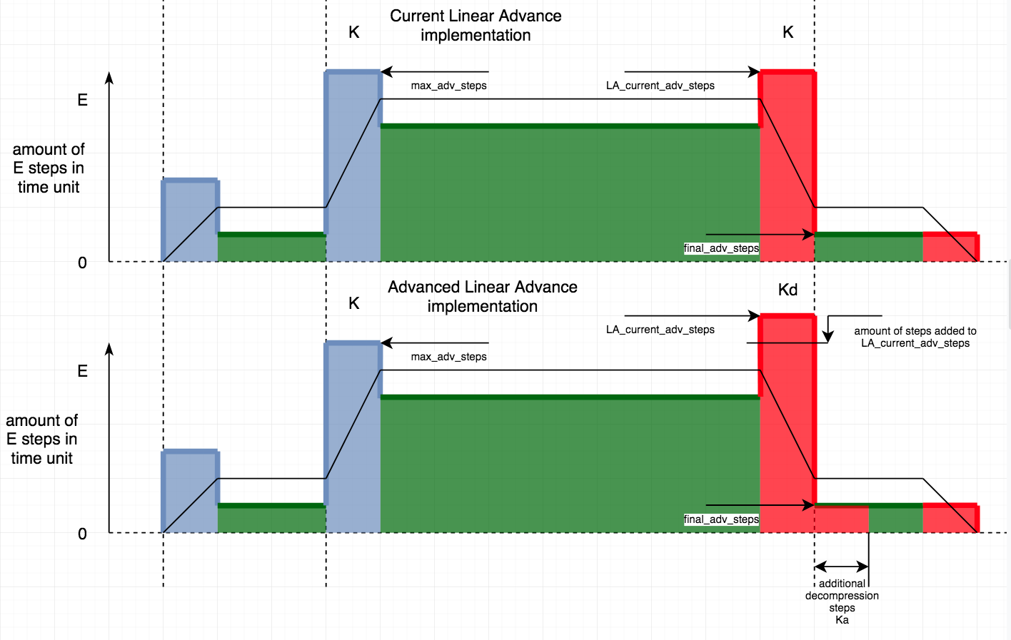
So, blue area is positive E pulses on acceleration, green - positive E pulses while cruising (LA_steps incremented from main isr) and red area - negative E pulses on deceleration. This is amount of steps (pulses) per time interval (like steps/second). Higher bar on graph - more pulses per second issued. Proportions is not real, just for illustration.
After acceleration, our LA_current_adv_steps reached block->max_adv_steps and stays at this value while cruising. In current LA, when block start deceleration, LA_current_adv_steps will be decremented until it reach block->final_adv_steps. I thought: why we're trying to change final_adv_steps that is unsigned int and can easily overflow when subtracting greater values? The easy way is just add required amount (*Kd) of steps to LA_current_adv_steps at deceleration point and adjust interval accordingly. That's it.
Additional decompression part require only setting value at deceleration, so those steps will be executed at beginning of next block with intervals (speed) of next block. So, the only question: how calculate values? I mean, what to use as reference for calculation and then apply Kd & Ka? For Ka may be we should calculate amount of steps based on block length?
sbasmanov
on 3 Jun 2020
why we're trying to change final_adv_steps that is unsigned int and can easily overflow when subtracting greater values?
True, we have to check and limit it to zero. Nonetheless, we should have the option to reach zero, if that much correction is required.
The easy way is just add required amount (*Kd) of steps to LA_current_adv_steps at deceleration point and adjust interval accordingly. That's it.
Additional decompression part require only setting value at deceleration, so those steps will be executed at beginning of next block with intervals (speed) of next block.
Yes, that's an easier way. But also less clean. And if we do it like this, we have to make sure those steps we add on each deceleration don't add up over mutliple segments. Especially for short segmens, where the additional decompression might not finish, we accumulate steps. May not be critical, I'm not sure.
So, the only question: how calculate values? I mean, what to use as reference for calculation and then apply Kd & Ka? For Ka may be we should calculate amount of steps based on block length?
I would use the same logic: Use a fraction of LA_final_adv_steps. But now, we add it to LA_current_adv_steps instead of substracting it from final. Might look like
block->final_adv_steps = next_entry_speed * comp;
if(current_nominal_speed >= next_entry_speed) {
  block->decomp_offset = block->final_adv_steps * (extruder_advance_Kd[active_extruder] - extruder_advance_K[active_extruder]) / extruder_advance_K[active_extruder];
  // Or without divide:
  // block->decomp_offset = next_entry_speed * block->e_D_ratio * (extruder_advance_Kd[active_extruder] - extruder_advance_K[active_extruder]) * settings.axis_steps_per_mm[E_AXIS];
  NOMORE(block->decomp_offset, block->final_adv_steps);
} else {
  block->decomp_offset = 0;
}
in planner. Works for Kd>K, so this should be checked during compiling. In stepper, it stays the same as before
block->decomp_speed = block->advance_speed * extruder_advance_K[active_extruder] / extruder_advance_Kd[active_extruder];
and we add decomp_offset to LA_current_adv_steps. Example: If K = 1 Kd = 1.5 , we get
// In planner.cpp:
block->decomp_offset = block->final_adv_steps * 0.5;
// -> Total decompression results in final_adv_steps + 0.5 * final_adv_steps, which were added to LA_current_adv_steps.
// In stepper.cpp, we get
block->decomp_speed = block->advance_speed * 1/1.5;
// Which is what it needs to be for full decompression. 1.5x faster than before.
Additional thoughts: If we define Kd as multiplier for K (Kd = 2.0 -> Kd_internal = K * 2.0), the math becomes easier, but it will be harder to tune for users - if you change K, you indirectly also change Kd. Same is true if we define it as a surplus / offset (Kd = 2.0 -> Kd_internal = K + 2.0). That's bad.
I currently think it's better to have easier tuning and slightly more expensive math. If it's frustrating to tune, it's not gonna be used much. But we want people to use it, because it's awesome 😄
XDA-Bam
on 3 Jun 2020
Hmm.. I went different way.
Yes, that's an easier way. But also less clean. And if we do it like this, we have to make sure those steps we add on each deceleration don't add up over mutliple segments. Especially for short segmens, where the additional decompression might not finish, we accumulate steps. May not be critical, I'm not sure.
As we're adjusting timer accordingly, all extra steps will be executed.
I currently think it's better to have easier tuning and slightly more expensive math. If it's frustrating to tune, it's not gonna be used much. But we want people to use it, because it's awesome
So, I changed approach and committed to my branch. Idea is still simple: K still works for acceleration, Kd works same way but for deceleration and Ka works same way, but for beginning of next segment. Additional steps are difference between max_adv_steps with K and max_adv_steps with Kd. So, if Kd>K there will be positive difference, If Kd
Same thing with additional steps - calculated same way as max_adv_steps for acceleration, but instead we issue negative E pulses. Think of it like it is deceleration with Ka at beginning of block. I seen somewhere in code, that K is a compression coefficient in mm of filament. So, I think we should keep meaning of this coefficients.
sbasmanov
on 3 Jun 2020
Oh, another explanation of what I do: on second graph, imagine that we adjust LA_current_adv_steps like if we decelerate from higher speed (let's say 100 instead of 80). So, we accelerated from 20 to 80, then decelerate from 100 to 20 :) And additionally decelerate at beginning of slow segment, same value as if it would be acceleration with Ka coefficient and timer intervals of cruise speed.
ps: is there any way to get source code of pattern generator from marlinfw.org? I tired changing values in gcode manually :)
sbasmanov
on 3 Jun 2020
ps: is there any way to get source code of pattern generator from marlinfw.org? I tired changing values in gcode manually :)
https://github.com/MarlinFirmware/MarlinDocumentation/tree/master/_tools/lin_advance
XDA-Bam
on 3 Jun 2020
https://github.com/MarlinFirmware/MarlinDocumentation/tree/master/_tools/lin_advance
Many thanks. Havent's seen this tree.
Ok, so, here is results:
- K0.7 A0 D0.7-> K0.7 A0 D1.65, step 0.05
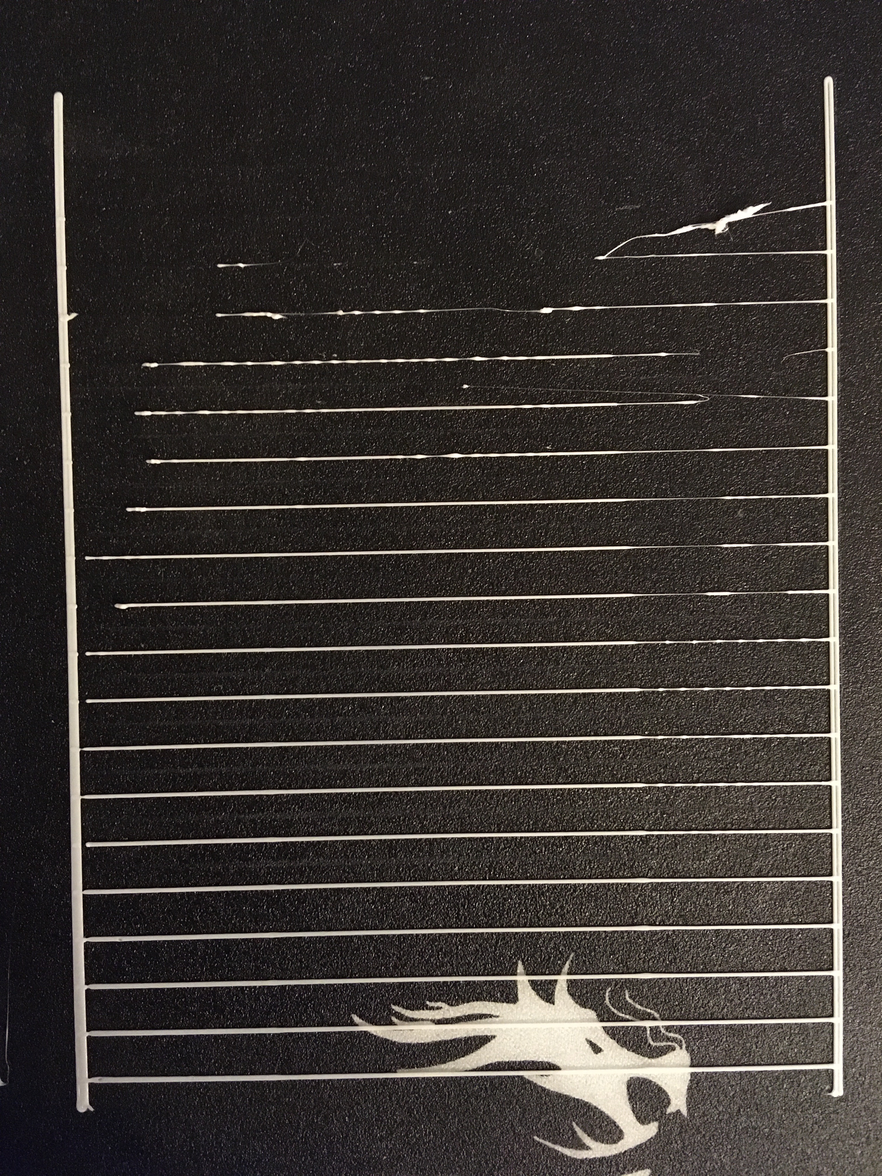
Broken upper lines in the beginning because of retract 6.5mm.
- C0.7 D0.7 A0 -> C0.7 D0.7 A0.95, step 0.05 (avoiding K as resets D&A to defaults).
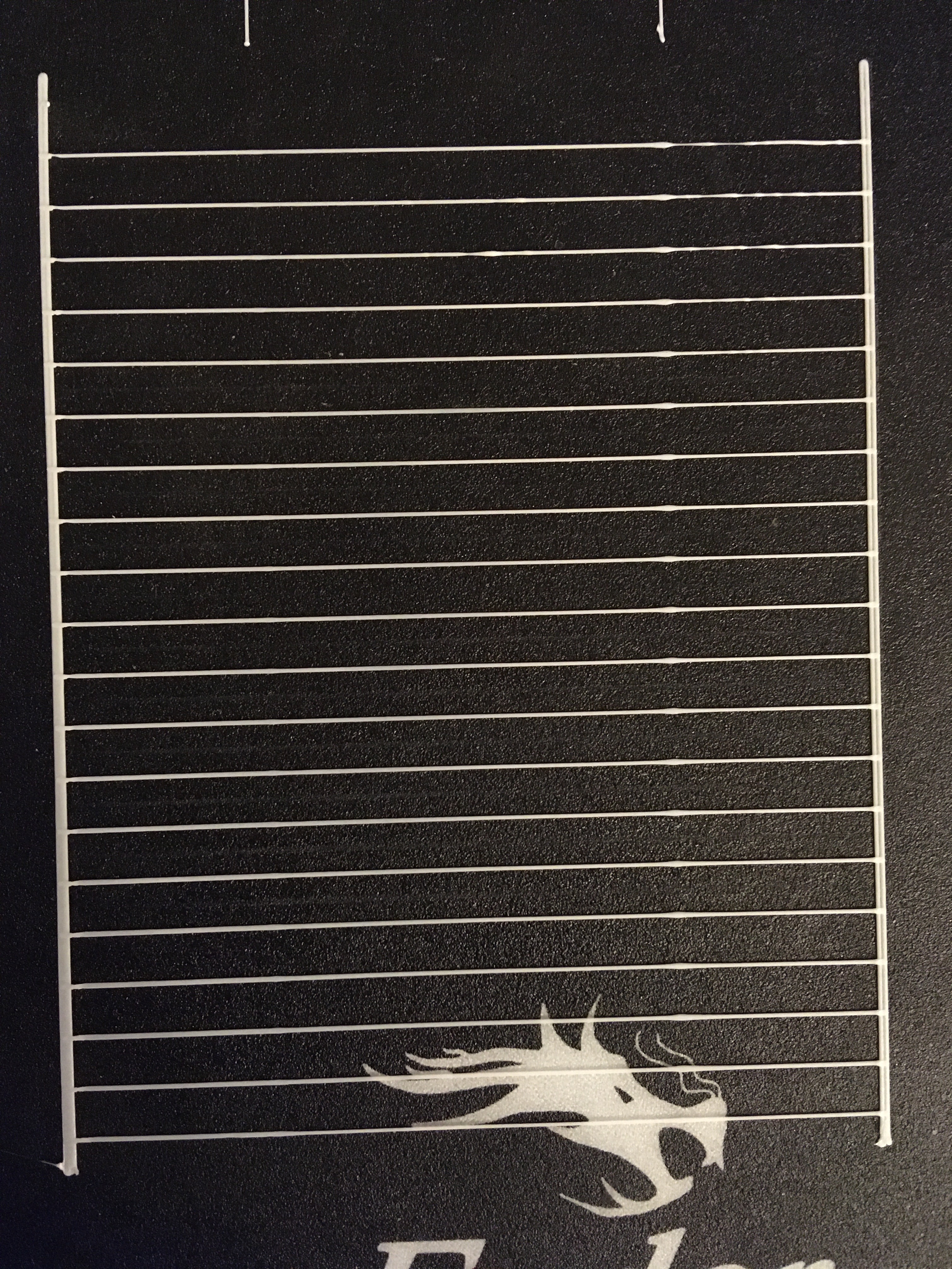
Seems it's possible that Ka will be needed in opposite way - to compensate previous retract :)
sbasmanov
on 3 Jun 2020
What I think I should try is shifting deceleration point for E to be earlier than block decelerate_after and adjust max_adv_steps if they overlap. So, scrolling back to my graphs, this is number 2.
sbasmanov
on 3 Jun 2020
What I think I should try is shifting deceleration point for E to be earlier than block decelerate_after and adjust max_adv_steps if they overlap. So, scrolling back to my graphs, this is number 2.
In some cases, for short blocks, there will be no cruising phase. We accelerate, reach peak speed and immediately decelerate. For this to work, you also have to check that your steps are above accelerate_until.
I also don't see the advantage - if you decompress 100 LA steps over a longer range instead of faster (current idea), you will still decompress 100 LA steps. The result/pressure should be close to identical. I'd rather invest a bit more time in tuning the current solution.
XDA-Bam
on 3 Jun 2020
I also don't see the advantage - if you decompress 100 LA steps over a longer range instead of faster (current idea), you will still decompress 100 LA steps. The result/pressure should be close to identical. I'd rather invest a bit more time in tuning the current solution.
Well, I can add one more parameter S that will define shift as (decelerate_after - accelerate_until) * S, where S from 0 to 1. If negative, it will limit max_adv_steps. Idea is to decompress 100 LA steps over same time as before, but do this early, so after decompression it will cruise at next_entry_speed until block ends. Yes, sounds complex, so may be try it later.
So, but what to do with current results? If we decelerate faster & more steps, it retracts way too much for next segment. Holding extruder at beginning of block doesn't help - bulge appears before slow segment. So, may be make if Ka is negative, it will add E steps instead of decrement?
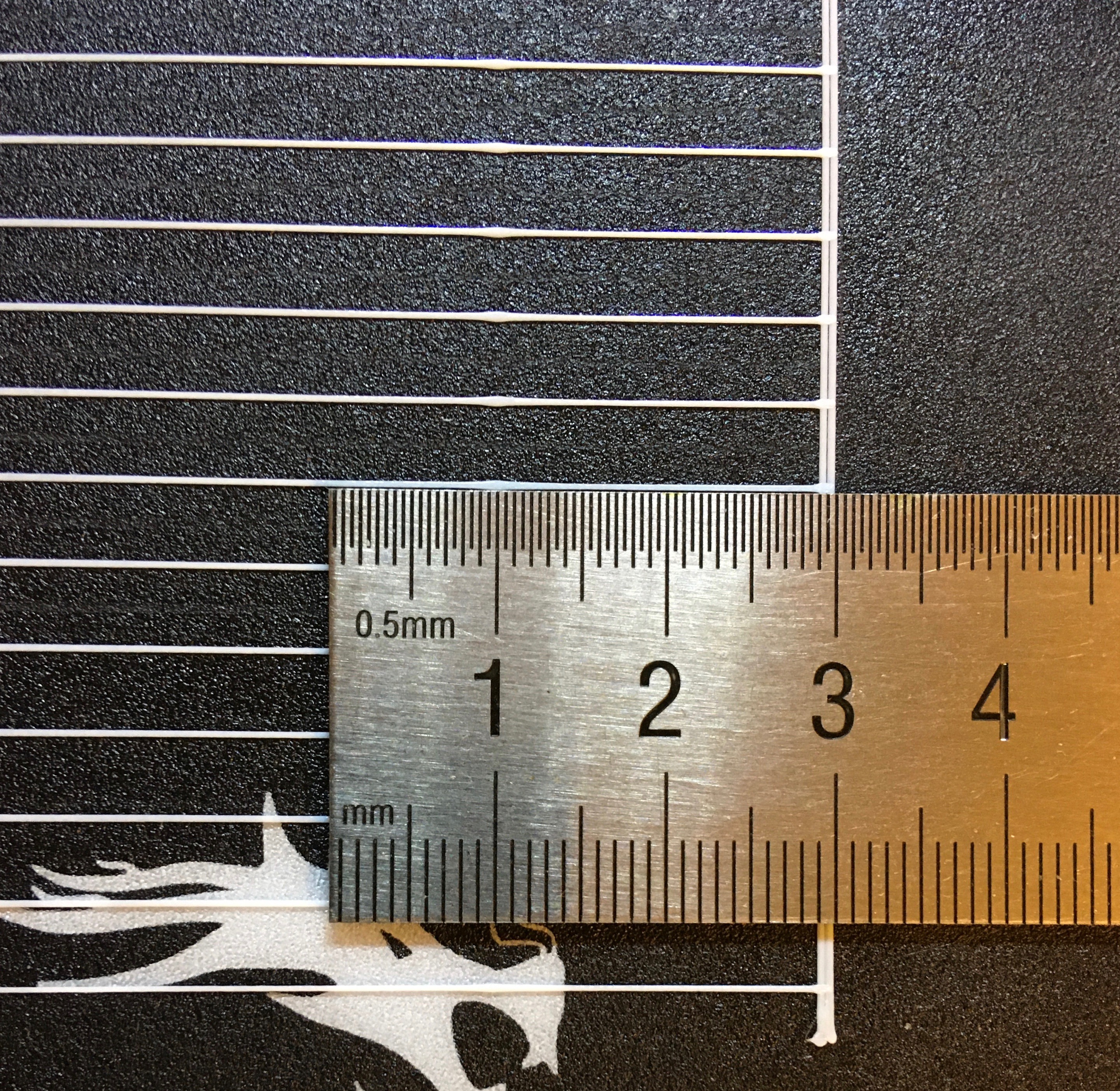
sbasmanov
on 3 Jun 2020
Well, I can add one more parameter S that will define shift...
May help, but will be tricky to cover all possible cases. And on segments where it should be applied but which are too short, results might be strange.
So, may be make if Ka is negative, it will add E steps instead of decrement?
Worth a shot. Kd higher, Ka negative to compensate.
XDA-Bam
on 3 Jun 2020
Committed last changes, added small txt with information. Result with C0.7 D0.95 A0-0.95 with 0.05 step:
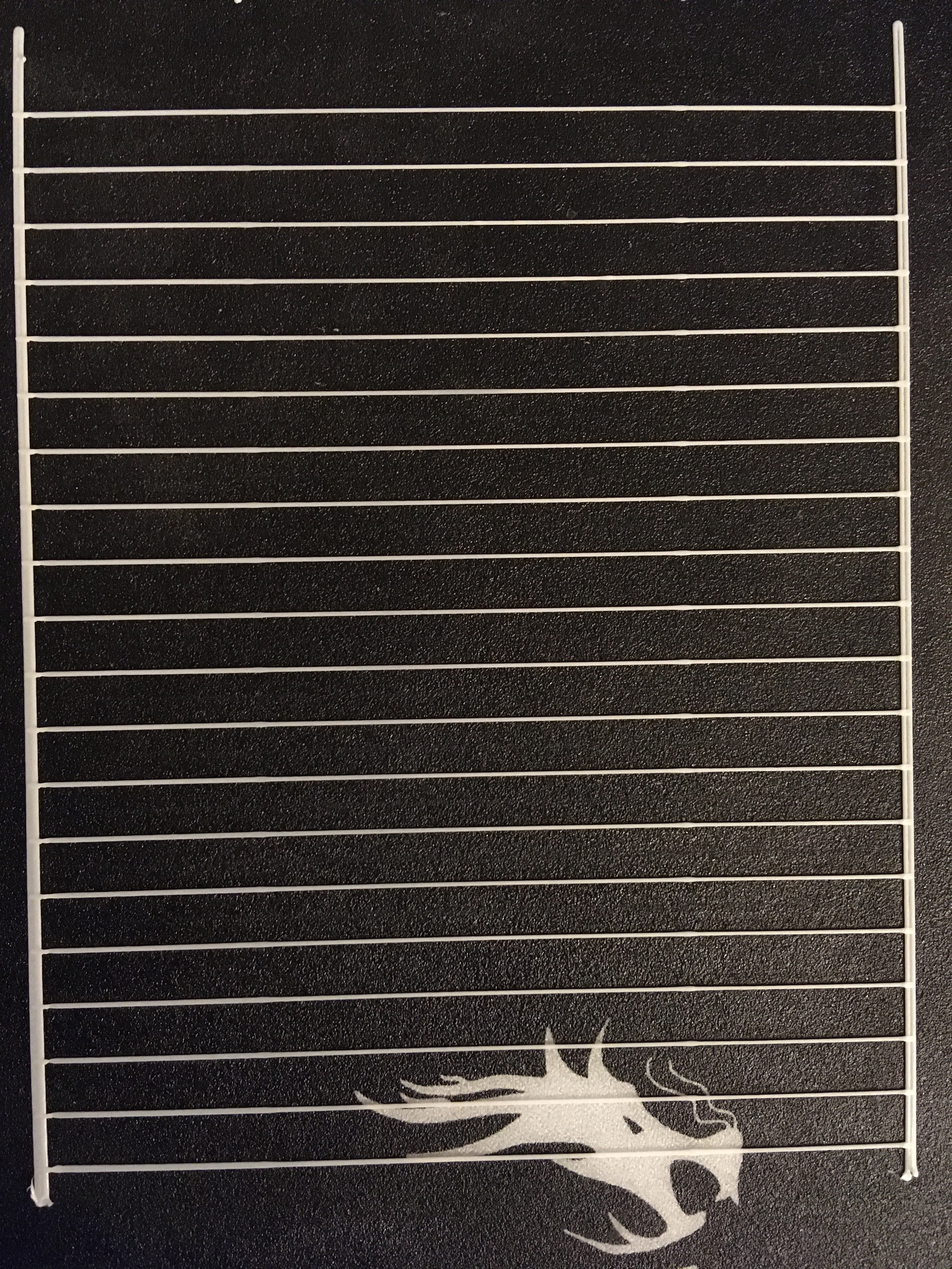
So, all this needs testing on different printers with different filaments & temperatures. Otherwise hard to say if works or not.
Worth a shot. Kd higher, Ka negative to compensate.
Reverted to be more logical - A>0 extrusion, A<0 - retraction.
sbasmanov
on 3 Jun 2020
I've tested your c74d955 today. Setting parameters seems to be working, printing is OK, nothing out of the ordinary But I'm seeing slight underextrusion at the very beginning of each line and at the beginning of the fast segments. It seems that the D coefficient still influences acceleration regions, although it shouldn't. Or maybe A is somehow working in reverse during acceleration?
I tried quite a number of patterns, but until we fix this, it's impossible to tune correctly.
XDA-Bam
on 4 Jun 2020
I think the problem is related to the fact that for the first, slow segment, next_entry_speed == current_nominal_speed is true in
if(next_entry_speed <= current_nominal_speed) {
  block->add_decomp_steps = next_entry_speed * extruder_advance_Ka[active_extruder] * step_mult;
} else {
  block->add_decomp_steps = 0;
}
and thereby, add_decomp_steps is not zero at the beginning of the fast segment. Then, in the stepper,
else if(LA_add_decomp_steps) {
  if(LA_add_decomp_steps > 0) {
    LA_add_decomp_steps--;
    LA_steps++;
  } else {
    LA_add_decomp_steps++;
    LA_steps--;
  }
  //Don't change LA_current_adv_steps here!
  interval = LA_isr_rate;
}
will run, although it should not. Instead, the last option should be run like in any "normal" acceleration phase:
else if (step_events_completed < decelerate_after && LA_current_adv_steps < LA_max_adv_steps) {
  LA_steps++;
  LA_current_adv_steps++;
  interval = LA_isr_rate;
}
I think the problem is related to the fact that for the first, slow segment, next_entry_speed == current_nominal_speed is true in
Hmm.. You're right. Just checked log and for slow->fast block new_entry_speed is current speed. So, yes, this add unneeded steps at acceleration. But that's very strange. next_entry_speed have to be real speed of next block. This is what planner does:
P: comp:3.43 mas:68 fas:68 nes:20.00 ads:0
P: comp:3.43 mas:68 fas:68 nes:20.00 ads:0
P: comp:3.43 mas:68 fas:68 nes:20.00 ads:0
P: comp:3.43 mas:68 fas:68 nes:20.00 ads:0
P: comp:3.43 mas:274 fas:255 nes:74.65 ads:0
P: comp:3.43 mas:274 fas:264 nes:77.28 ads:0
P: comp:3.43 mas:274 fas:255 nes:74.65 ads:0
P: comp:3.43 mas:274 fas:274 nes:80.00 ads:0
P: comp:3.43 mas:274 fas:255 nes:74.65 ads:0
P: comp:3.43 mas:274 fas:274 nes:80.00 ads:0
P: comp:3.43 mas:274 fas:255 nes:74.65 ads:0
P: comp:3.43 mas:274 fas:274 nes:80.00 ads:0
P: comp:3.43 mas:274 fas:255 nes:74.65 ads:0
P: comp:3.43 mas:274 fas:274 nes:80.00 ads:0
P: comp:3.43 mas:274 fas:255 nes:74.65 ads:0
P: comp:3.43 mas:274 fas:274 nes:80.00 ads:0
P: comp:3.43 mas:274 fas:255 nes:74.65 ads:0
P: comp:3.43 mas:274 fas:264 nes:77.28 ads:0
P: comp:3.43 mas:274 fas:68 nes:20.00 ads:0
P: comp:3.43 mas:68 fas:68 nes:20.00 ads:0
P: comp:3.43 mas:68 fas:68 nes:20.00 ads:0
P: comp:3.43 mas:68 fas:68 nes:20.00 ads:0
P: comp:3.43 mas:68 fas:68 nes:20.00 ads:0
Ok, will fix it. So, I did more tests and prints and I'm little disappointed. I tried to print test cube with C0.7 D0.8 A0. When it prints long enough lines - everything is fine. When it starts filling 20x20mm area with zig-zag - underextrusion accumulates on small lines, so it stop extrusion at all. When it start printing walls (after zig-zag) extrusion slowly restore. So, seems the problem somewhere else, but I don't see where exactly. Everything seems correct, but something wrong :( And another interesting thing. Initially, I used stable 2.0.x and tried LA here without success - it was printing slower and quality degraded. So, I disabled it completely. Yesterday I printed test cube with basic K0.7 (no extra params) and it was much better than I seen before. That means something changed in bugfix, that greatly affects how LA works. I will try to collect debug log when printing cube, may it will help to find where the problem is.
sbasmanov
on 4 Jun 2020
When it starts filling 20x20mm area with zig-zag - underextrusion accumulates on small lines, so it stop extrusion at all
I think this may be related: If we always run the if(LA_add_decomp_steps > 0) {-part during acceleration, LA_current_adv_steps++ isn't executed, so this counter is wrong most of the time. That will have unforeseen consequences and the error might accumulate over time, especially on consecutive short segments.
XDA-Bam
on 4 Jun 2020
When A0 this never gets executed, as block->add_decomp_steps = next_entry_speed * extruder_advance_Ka[active_extruder] * step_mult;. And I tried to print with A0 - got underextrusion. So, seems something happen with faster decompression on very short segments. Probably only debug log will show what exactly. So, I updated code, now You can try setting A alone, without setting D, so just M900 Kxx Ayy.
sbasmanov
on 4 Jun 2020
Tested your latest fix today. Underextrusion at the beginning of each line and the beginning of the fast segments is still present. Seems unchanged. That is with A=0. Increasing A improves the unerextrusion a bit (as expected).
I think in stepper around line 1914
LA_current_adv_steps += current_block->decomp_steps;
LA_isr_rate = current_block->decomp_speed;
LA_add_decomp_steps = current_block->add_decomp_steps;
is run waaay before it should be. But I didn't check via serial, yet. Might dig into that later.
XDA-Bam
on 5 Jun 2020
is run waaay before it should be. But I didn't check via serial, yet. Might dig into that later.
This place executed exactly on first deceleration isr. I checked it before. I don't see underextrusion until it starts to fill areas with short lines. This where it starts and recovers only on long lines. Looks like when segment is very short, new interval value and amount of steps being incorrectly calculated. Had no chance to debug yet.
sbasmanov
on 5 Jun 2020
This place executed exactly on first deceleration isr. I checked it before.
I know it should be. The code is clear. But the results I'm getting make it look like it's not. But maybe the source of the underextrusion is something totally different. Just looks similar.
This is on the most recent commit of LA-finetune (fd3a52d), running C0.65 D0.75:0.1:1.15 A0 for bottom five lines and C0.75 D0.85:0.1:1.25 A0 for top lines:
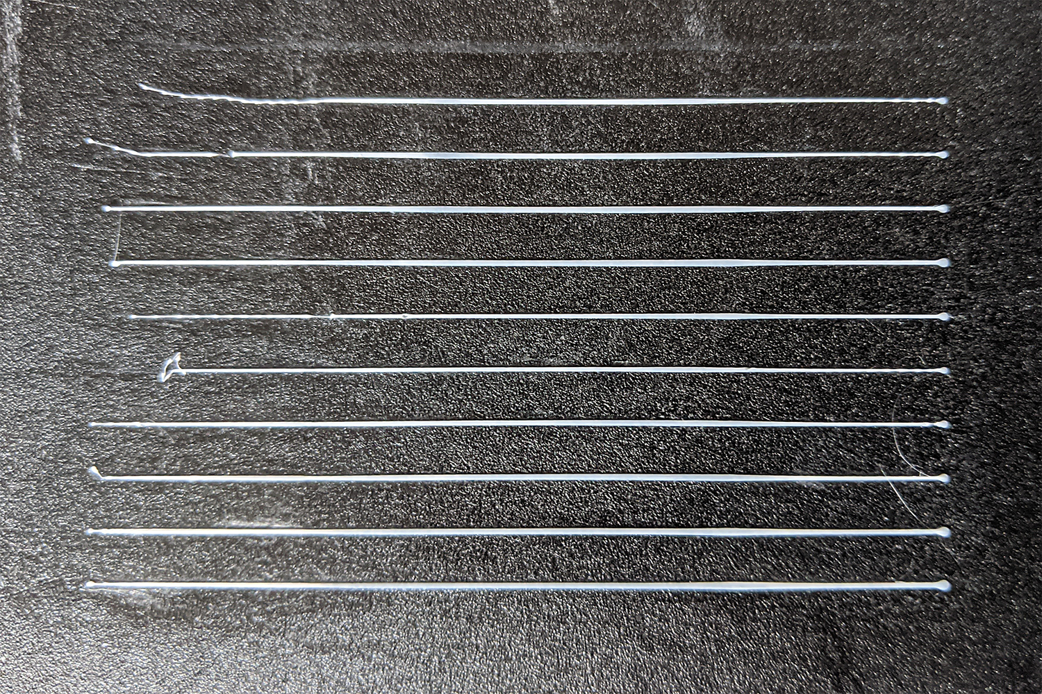
Severe underextrusion at the beginning of the line, slight underextrusion after first speed change. You may not notice this, if you're running with A>0, because that improves the underextrusion. Try it with A=0.
XDA-Bam
on 5 Jun 2020
Hmm.. Because line end looks normal, I think this is retract between lines. Have you changed it? I printed cube with K0.7 and retract 2mm instead of 6.5mm and there were no stringing and other problems. If line finish with almost zero pressure, extra retract pulls filament way too much, this is why you get problems at beginning of next line. Try same pattern with 1 or 2mm retract?
sbasmanov
on 5 Jun 2020
The one above is with 3 mm of retract. I will try it with less.
XDA-Bam
on 5 Jun 2020
The one above is with 3 mm of retract. I will try it with less.
This should be enough. So, definitely, this needs debugging. I don't understand, what happen after last line and retract, so next line gets this underextrusion.
So, if lines go like this: seg1,seg2,seg3,retract,travel,seg1,seg2,seg3,... and we added extra steps to LA_current_adv_steps at deceleration of seg2, next time when LA gets chance to do anything is when seg1 of next line being executed. But in this case, we should see normal line beginning and underextrusion in middle of seg1. But instead, we see opposite - underextrusion in beginning of seg1 and it becomes normal close to ending. So, what happen after seg3,retract,travel? Probably we need to count real E steps somewhere to see how total extruded amount is changing after each block and retract. Or may be separately - count positive and negative pulses for each block and dump values to serial just before block discarded?
sbasmanov
on 5 Jun 2020
Just tested 1 mm retract and it didn't change anything. But I just realized that retracts are G1 moves - each retract & un-retract is a block/segment. block->use_advance_lead is false for retracts, but true for un-retracts! I don't know what block->e_D_ratio evaluates to in this case, since the divisor (block->millimeters) is zero. But next_entry_speed < current_nominal_speed will be true for the un-retract, because
current_nominal_speed = sqrt(block->nominal_speed_sqr);
// with
block->nominal_speed_sqr = sq(block->millimeters * inverse_secs);
// and
block->millimeters = 0 + ABS(steps_dist_mm.e);
// for X, Y and Z steps below MIN_STEPS_PER_SEGMENT
That means
block->add_decomp_steps = next_entry_speed * extruder_advance_Ka[active_extruder] * step_mult;
will be run with whatever value resulted for step_mult in the un-retract move. In the stepper, I am not sure what happens, because I'm not sure what accelerate_until and decelerate_after eval to for an exclusive extruder move (retract or un-retract). I guess those will just describe the extruder accel and decel in this case?
That would mean that the extruder movement during the un-retract move has some unpredictable influence on advance steps, which then change the extruder movement during that same un-retract. Seems like this could be our problem!
XDA-Bam
on 5 Jun 2020
Hmm.. Sounds interesting. I think it's possible to check this idea - remove retracts/unretracts from test pattern gcode at all. Yes, this will result in some stringing, but at least we will see if that was unretract affecting LA.
sbasmanov
on 5 Jun 2020
Good idea to remove the retracts. I just tested it and surpisingly, it did not improve. If anything, it's a tiny bit worse than with retracts 🤔
XDA-Bam
on 5 Jun 2020
I start thinking that in total, we retract more than extrude and this being accumulated. If this is true, that means that entire idea doing extra retraction steps is wrong. But what to do instead?
How I understand this: extruder have time lag comparing to axis. To compensate this, we choose K big enough, so we have right amount of filament at right place. Same thing probably happen at deceleration - axis is already at lower speed, but extruder still pushing filament (plus, Bowden works like spring here). So, somehow this have to be compensated as well. But total amount added minus subtracted should zero. If we add more retraction steps on deceleration, this leads to situation, where we added 100 steps, but subtracted 110, so in total -10 steps for segment. And with every other segment, total amount slowly decreasing. Probably, adding steps with A should help, but this being executed only if next block is slower and if block is short, there is not enough time to execute all extra (A) steps, because execution speed is cruise speed, not acceleration speed.
Could be true?
sbasmanov
on 5 Jun 2020
I start thinking that in total, we retract more than extrude and this being accumulated. If this is true, that means that entire idea doing extra retraction steps is wrong. But what to do instead?
That should be the case, if D>C and A<D-C. For A>D-C, I think we actually extrude overall more than requested. We might want to fix something like A=D-C, which would rub us of one tuning parameter.
Probably, adding steps with A should help, but this being executed only if next block is slower and if block is short, there is not enough time to execute all extra (A) steps, because execution speed is cruise speed, not acceleration speed.
Could be true?
I've tested with A>D-C and still got some underextrusion, but that was also after a couple of lines with A<=D-C, so maybe the error accumulated there and still caused the issue in the later lines. I'll test it again, but excluding A<D-C this time.
EDIT: The relation of A and D-C is actually more complicated than I've explained above, , because A and D are calculated with different speeds. That means, A=D-C will only be "neutral", if the speed within a segment is constant - which is not a typical use case.
XDA-Bam
on 5 Jun 2020
Maybe we should go back to "the old way" of influencing LA by changing the boundary conditions and not by just adding stuff to LA_current_adv_steps. When doing the latter, it's really hard to predict what happens once we do not reach final_adv_steps or max_adv_steps in a segment. And as I said before, errors might accumulate, especially on consecutive short segments.
XDA-Bam
on 5 Jun 2020
Maybe we should go back to "the old way" of influencing LA by changing the boundary conditions and not by just adding stuff to LA_current_adv_steps
May be this is true. I don't know. Until I collect debug log, it's hard to say what's wrong. But I have another interesting result. Today was in shop and got 1.9 ptfe tube. So, installed new tube, made it little shorter than original one and installed insert in hotend, decoupling from main ptfe tube. This is standard test 0-2, 20-80-20. Only forgot to turn on bed leveling, so lines little wider :) And retract was 2mm, too short for K<1.

So, this shows that bulge issue 100% related to bowden length. Shorter and more tight tube - different result.
sbasmanov
on 7 Jun 2020
Quick update: I've been re-working your code the past days and have set up three different ways to influence LA in three branches:
- Fast decompression + additional decompression steps in the following segment
- Fast decompression + offset to begin decompression before deceleration
- Fast decompression + fast recompression
All three use math which is different from your approach in that they don't manipulate LA_current_adv_steps, but use it as a normal counter, just like regular LA. Limits are applied in planner, ensuring that nothing underflows or overflows. Also, the decompression steps are computed based on the speed difference (current nominal vs. next entry), which saves a divide and makes it overall more logical, I think.
I'm getting solid results with the "decompression before deceleration"-approach. Overall, though, I can produce pretty test patterns, but in real prints, the results (corner bulging, etc.) are not visibly improved using sensible tuning parameters.
When using more extreme parameters, approach (1) starts to give underextrusion after corners (not surprising), approach (2) starts to give underextrusion before _and_ after corners (probably re-compression too slow?) and approach (3) is indeed giving slightly sharper corners but creates underextrusion on the very first layer (still investigating).
All in all, no clear winner amongst these three, but (1) seems to be useless outside of test patterns. I think (3) is very hopeful, but I have to figure out where I'm loosing that filament on the first layer.
XDA-Bam
on 9 Jun 2020

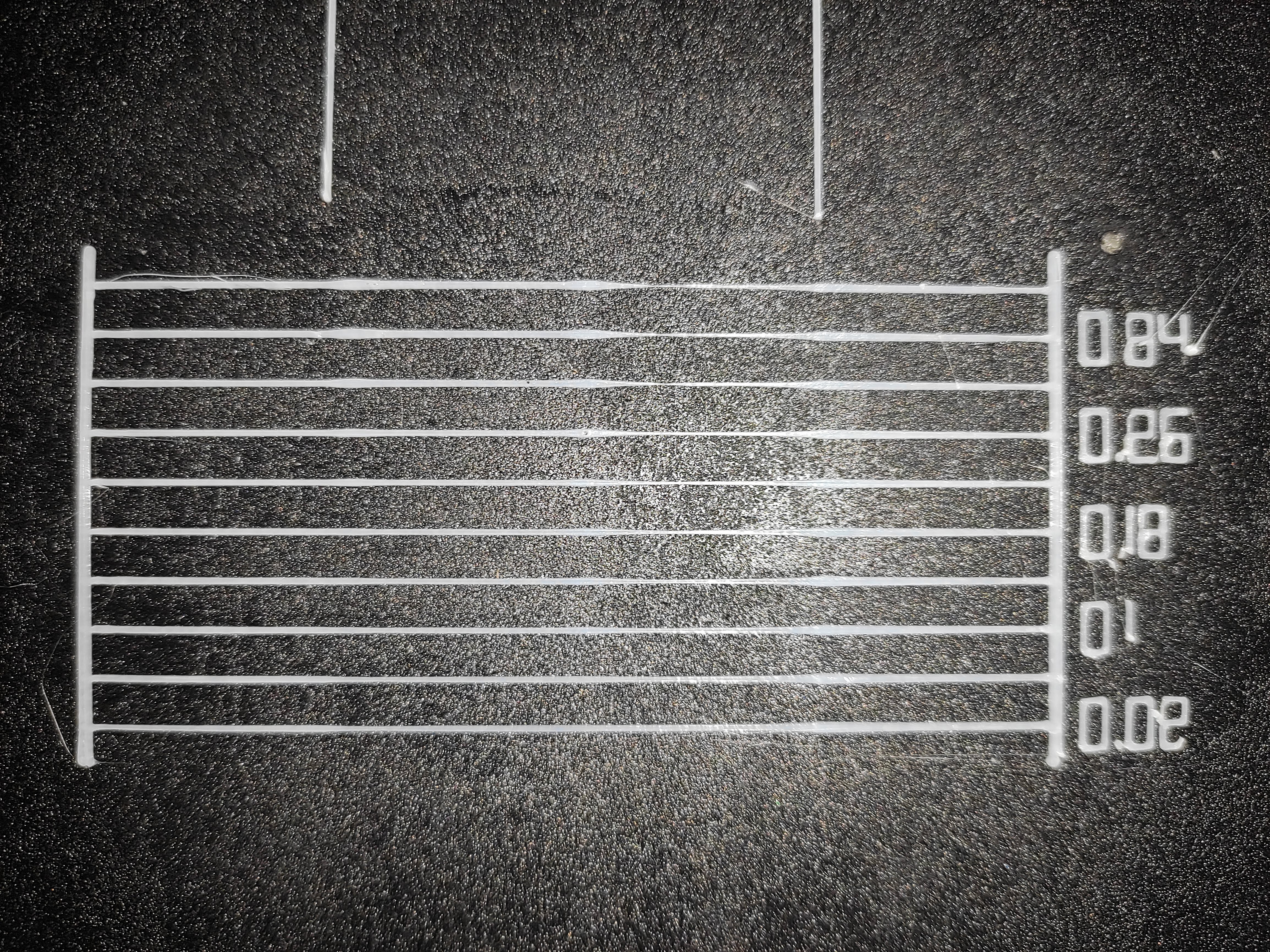
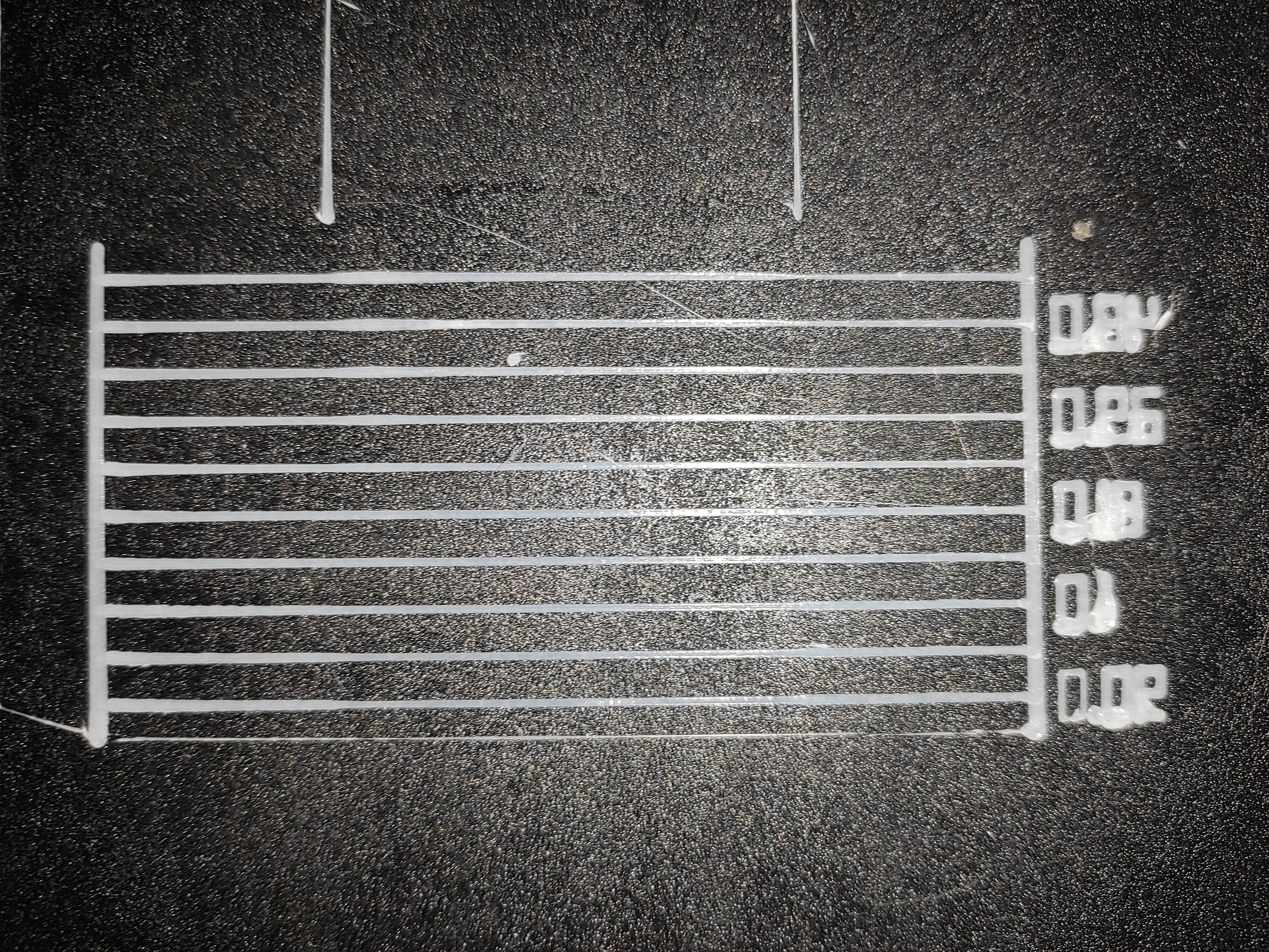
Original

qwewer0
on 9 Jun 2020
XDA-Bam, interesting ideas. I'll try it on my printer soon. Regular work came back, so two month holidays is over :(
qwewer0, is it direct extruder?
sbasmanov
on 9 Jun 2020
Yes, it is a direct extruder. My usual K value is 0.18
qwewer0
on 9 Jun 2020
If only bowden-setups are affected by the blob an effect described by Alex Kenis - Fancy Bowden couplings and fake tubing tests - hysteresis testing is likely to be a dominant reason.
In short:
It takes some time until the bowden-tube returns to its original shape after releasing a stretching force. The effect is highly nonlinear.
AnHardt
on 9 Jun 2020
@qwewer0 Thanks for trying it out. Could you edit the post to show, which settings were varied for which print?
If you also varied K: Basically, the way to tune this would be to first tune K (=C) to perfection, without setting D and O or A. So, the default, auto-generated test pattern would still be the way to go. As soon as you know K (=C), you can start to tune D:
M900 C0.2 D0.2 A0
// Test pattern line 1
M900 C0.2 D0.22 A0
// Test pattern line 2
M900 C0.2 D0.24 A0
// Test pattern line 3
...
If D looks decent, A/O can be tuned:
M900 C0.2 D0.24 A0.05 // or O0.25 for offset (needs higher values than A)
// Test pattern line 1
M900 C0.2 D0.24 A0.1
// Test pattern line 2
M900 C0.2 D0.24 A0.15
// Test pattern line 3
...
When increasing A or O, it might be necessary to slightly decrease D to compensate. But D should never be below C, otherwise you will get even bigger blobs. For version (3), there is no A or O, you just tune C, then tune D.
AnHardt:
If only bowden-setups are affected by the blob an effect described by Alex Kenis - Fancy Bowden couplings and fake tubing tests - hysteresis testing is likely to be a dominant reason.
In short:
It takes some time until the bowden-tube returns to its original shape after releasing a stretching force. The effect is highly nonlinear.
Yes, that's what I would have expected. Nice test and explanation in the video. There's also additional factors such as filament "folding" inside the tube, as it's inner diameter is wider than the filament itself. Any linear solution will overcompensate and undercompensate at different times during the decompression and compression phases.
Nonetheless, I think a first order linear correction of the current behaviour can still reduce the mean pressure deviation from our virtual target pressure in the nozzle. Also, any non-linear solution will definitely overburden each and every AVR board - when running LA + JD on bugfix-2.0.x, reactions to inputs on my printer are already delayed massively and sometimes fully lost.
XDA-Bam
on 9 Jun 2020
@XDA-Bam My bad, I used the default pattern calibration, so only K is used. I will retest everything when my print is done in 10-11 hours.
qwewer0
on 9 Jun 2020
@XDA-Bam My bad, I used the default pattern calibration, so only K is used. I will retest everything when my print is done in 10-11 hours.
Interesting nonetheless, because in this case, all patterns should look like the original. (1) does, but (2) and (3) do not. So, good test. Gotta fix that.
EDIT: (1) also does not, but it's harder to see. Probably a bug in updating/storing the coefficients.
XDA-Bam
on 9 Jun 2020
Hi everyone. Sorry, had very busy time, so didn't test all code yet. But finally I did small update to printer and got this result:

Standard test from 0 to 1 with 0.1 step. The only difference is this:

1.9 ptfe tube almost twice shorter than original. Now I have to calibrate retract and can go with K=0.3. So, tube greatly affects. I'll try to adjust other params to see if that will remove bulge completely.
sbasmanov
on 17 Jun 2020
@Liger0 still an issue?
 boelle
on 21 Jun 2020
boelle
on 21 Jun 2020
On the latest stable firmware, of course.
I haven't followed this test discussion because my printer is actually broken to do any test.
Liger0
on 21 Jun 2020
On the latest stable firmware, of course.
Please test the bugfix-2.0.x branch to see where it stands. If the problem has been resolved then we can close this issue. If the issue isn't resolved yet, then we should investigate further.
thinkyhead
on 21 Jun 2020
Quick update: I have pushed the latest commits today and will stop working on this for now. It's quite possible to massively improve the bulge on the test pattern. But in actual prints, those settings then lead to slight underextrusion before or in some cases before _and_ after corners. What looks good in the pattern is "overtuned" in practice - and less aggressive settings have very little effect on actual prints.
The offset approach was the most promising, because with unchanged decompression (D = C), this essentially implemented coasting in LA. When tuned right - in my case around O = 4 - this lead to slightly sharper corners without many issues. But considering the tiny gains this approach is giving me and how crudely it affects LA, I can't see it being implemented in Marlin.
Until some major changes are applied to the planner, which allow us to look ahead a handful of mm and plan out LA across multiple blocks, I don't think there's much to improve. Until then, I support @sbasmanov in opting for hardware tuning:
- Shorten your bowden tubes
- Switch to PTFE with 1.9 mm inner diameter (instead of 2.0)
- Perform the washer mod on the hotend
XDA-Bam
on 29 Jun 2020
I agree with @XDA-Bam - what looks good on test pattern, leads to bad results in real prints. Especially on small segments (zig-zag skin). To better understand what's going on, very verbose uart debugging is needed, which is not possible on avr platform. I'm still waiting for my skr mini :(
As to hardware mod - this seems to provide much better results comparing to software tuning. I'll post complete ender 3 guide when finish my work.
sbasmanov
on 30 Jun 2020
I have a stock Ender 3 with Bowden tube setup (the original tube in fact) and I have also got the bulges at acceleration/deceleration in the K-factor calibration test. My filament is not the greatest, AMZ3D White PLA, which has been exposed to significant humidity in the past but has been stored in a dry box for last two weeks.
With LA enabled, the quality of small circular features (e.g. M6 hole/post) is significantly worse than when LA is disabled. I'd describe it as bulges at different points around the circumference on each layer, leading to a very rough look. This seems to correlate with very uneven speed/acceleration of the hotend as it goes around the circumference of the circle, as compared to when LA is disabled. With LA enabled, it seems to speed up for a segment of the circle and then slow down for the rest of the circle.
I'm using the latest TH3D Unified Firmware. I don't know how well synchronized that is with this repo.
 doxxx
on 7 Jul 2020
doxxx
on 7 Jul 2020
This issue is stale because it has been open 30 days with no activity. Remove stale label / comment or this will be closed in 5 days.
![github-actions[bot] picture](https://avatars2.githubusercontent.com/in/15368?v=4&s=40) github-actions[bot]
on 7 Aug 2020
github-actions[bot]
on 7 Aug 2020
This issue has been automatically locked since there has not been any recent activity after it was closed. Please open a new issue for related bugs.
github-actions[bot]
on 12 Oct 2020
Related issues
 pubalan12
·
4Comments
pubalan12
·
4Comments
 Bobsta6
·
3Comments
Bobsta6
·
3Comments
 manianac
·
4Comments
manianac
·
4Comments
 spanner888
·
4Comments
spanner888
·
4Comments
 modem7
·
3Comments
modem7
·
3Comments
Most helpful comment
I did more different tests and now I see three ways to fight with bulge :)

So, graphs - black line is axis speed, blue line is E speed. Not real, just for illustration.
So, may be somebody else have other ideas? May be I missing something?
But in any case I think we need to rewrite LA code first, to split acceleration & deceleration parts completely, so they can be adjusted independently.