Marlin: [FR] Working TOUCH_UI_FTDI_EVE support
Bug Description
The TOUCH_UI_FTDI_EVE does not work on marlin 2.0.1 or 2.0.x
i tried on Ramps, Arduino, SKR Pro, Fysetc S6 and SKR 1.3
the compiling issue https://github.com/MarlinFirmware/Marlin/issues/16534 is sloved.
but now only the display back light is on. i tried a lot different configurations but the result was every time the same.
Green screen while booting and after this backlight is on and display black.
Only if disconnect the MISO pin, on the display is the notification Release to begin screen calibration


with the marlin version from fysetc the display works pefect.
https://github.com/FYSETC/Marlin-2.0.x-FYSETC/tree/S6/BUG-FIX-CLCD

i also copied the folder ftdi_eve_touch_ui from fysetcs marlin in the marlin 2.0.1 branch after this the display works also but only with s6 board and SKR pro.
copy the ftdi_eve_touch_ui folder to the actual bugfix version does not work because there comes a lot of errors.
My Configurations
here are my configs that i actual work on my printer. (TOUCH_ui Folder is from fysetc)
Config_SKRPRO_MMU2_FTDI2.0.1WithFysetcTouchUI.zip
Steps to Reproduce
- download marlin 2.0.1
- use my config and connect a ftdi display to the board
- compile it with original
ftdi_eve_touch_uifolder from the marlin branch Expected behavior: [Display doesnt work] - compile it again with fysetc
ftdi_eve_touch_uifrom the marlin branch Expected behavior: [Display does work]
Additional Information
I also noticed that the #defines from the cofiguration.adv are not taken over.
As an example you select //#define CLCD_USE_SOFT_SPI in config.adv but the display still works with the normal SPI pins on EXP2.
but if you change it as follows in the pin_mappings.h
#ifdef SKR_PRO_TFT_PINMAP
  #ifndef __MARLIN_FIRMWARE__
    #error This pin mapping requires Marlin.
  #endif

  #define CLCD_SPI_CS PG10 //PD11
  #define CLCD_MOD_RESET PF11 //PG2

  //#define CLCD_USE_SOFT_SPI
    // #define CLCD_SOFT_SPI_MOSI PG3
    //#define CLCD_SOFT_SPI_MISO PG4
    //#define CLCD_SOFT_SPI_SCLK PA8 // PORTA3 Pin 7
#endif
the display is now controlled by the defined pins (backlight goes on) but unfortunately not correctly because the display is only switched on but nothing is displayed. so Software_SPI isnt work correctly
the same problem even if the CS and PD pin is only defined in config.adv the display is not controlled at all.
also this must happen in pin_mappings.h as mentioned above.
define CLCD_SPI_CS PG10 //PD11
define CLCD_MOD_RESET PF11 //PG2
`
next problem is now
if we use the LCD on the hardware spi bus we cant connect a sd card module.
as soon as i have connected the sd card module to the spi bus of the display the display shows only strange things
is it possible to use sd card modul with software spi?
I hope this is written understandably.
 TB1405
All 179 comments
Someone will have to finish porting support for this display into bugfix-2.0.x using the FYSETC fork as a reference.
 thinkyhead
on 22 Jan 2020
thinkyhead
on 22 Jan 2020
@thinkyhead maybe you have any idea because the issue with sd card ?
EDIT: My SD Card modul is the problem i connect the sd card modul from the smart discount controller and it works.
and one more question will this display be supported in the future if for example new submenus are created. As far as I know these would have to be created in the FTDI Eve program.
TB1405
on 22 Jan 2020
I don't know whether this thread is still active, but I suggest putting a resistor on the MISO line, as someone else had run into problems without one. If in fact there is a software fix, I would find it to be interesting and worth additional investigation.
 marciot
on 24 Feb 2020
marciot
on 24 Feb 2020
My SD Card modul is the problem i connect the sd card modul from the smart discount controller and it works.
Interesting. I do not recommend sharing the SPI bus between the FTDI display and the SD card. If you need to use an SD card, connect it to the SPI pins and run the FTDI display off some other pins using the software SPI option.
one more question will this display be supported in the future if for example new submenus are created. As far as I know these would have to be created in the FTDI Eve program.
No, the display code was developed at LulzBot (I wrote it). We could not use FTDI's closed-source tools so we wrote our own code from scratch. Some menus might get added in the future if anyone pays me to do it. Like right now I doing some work for CocoaPress :)
marciot
on 24 Feb 2020
I don't know whether this thread is still active, but I suggest putting a resistor on the MISO line, as someone else had run into problems without one. If in fact there is a software fix, I would find it to be interesting and worth additional investigation.
I’m watching this issue since I have an FT810 that I couldn’t get working with Marlin’s version on an SKR 1.3 & 1.4 (never tried Fysetc’s fork/don’t have an S6 board).
Edit: Here's the related issue with more info and what some of us have tried in the past to get these panels working: https://github.com/MarlinFirmware/Marlin/issues/16534
 thisiskeithb
on 24 Feb 2020
thisiskeithb
on 24 Feb 2020
my touch_eve is arrived (Fysetc 5" (https://es.aliexpress.com/item/4000628057351.html)). i want to test it in a SKR E3 DIP and Ramps+ReARM
~~~
define TOUCH_UI_FTDI_EVE
define LCD_HAOYU_FT810CB
~~~
my first test i have hit the error https://github.com/MarlinFirmware/Marlin/issues/16534#issuecomment-573382828. add
~~~patch
diff --git a/Marlin/src/HAL/STM32F1/HAL.h b/Marlin/src/HAL/STM32F1/HAL.h
index ff42beb92..48c9e8605 100644
--- a/Marlin/src/HAL/STM32F1/HAL.h
+++ b/Marlin/src/HAL/STM32F1/HAL.h
@@ -47,6 +47,9 @@
#include "msc_sd.h"
#endif
+
+#define pgm_read_ptr_near(addr) pgm_read_ptr(addr)
+
// ------------------------
// Defines
// ------------------------
~~~
in src/HAL/STM32F1/HAL.h seems silence the error
now set a custom pin map
add
~~~patch
diff --git a/Marlin/src/pins/stm32f1/pins_BTT_SKR_E3_DIP.h b/Marlin/src/pins/stm32f1/pins_BTT_SKR_E3_DIP.h
index fef8eeb61..13f87a099 100644
--- a/Marlin/src/pins/stm32f1/pins_BTT_SKR_E3_DIP.h
+++ b/Marlin/src/pins/stm32f1/pins_BTT_SKR_E3_DIP.h
@@ -220,6 +220,15 @@
#endif // HAS_SPI_LCD
+#if ENABLED(TOUCH_UI_FTDI_EVE)
- #define CLCD_USE_SOFT_SPI
- #define CLCD_MOD_RESET EXPA1_08_PIN
- #define CLCD_SPI_CS EXPA1_04_PIN
- #define CLCD_SOFT_SPI_MOSI EXPA1_03_PIN
- #define CLCD_SOFT_SPI_MISO EXPA1_09_PIN
- #define CLCD_SOFT_SPI_SCLK EXPA1_05_PIN
+#endif // TOUCH_UI_FTDI_EVE
+
//
// SD Support
//
~~~
after this now fail in:
~~
Marlin/src/lcd/extui/lib/ftdi_eve_touch_ui/screens/advanced_settings_menu.cpp:141:8: error: macro "GET_TEXT" passed 4 arguments, but takes just 1
))
^
Compiling .pio/build/STM32F103RE_btt/src/src/lcd/extui/lib/ftdi_eve_touch_ui/screens/confirm_start_print_dialog_box.cpp.o
Compiling .pio/build/STM32F103RE_btt/src/src/lcd/extui/lib/ftdi_eve_touch_ui/screens/confirm_user_request_alert_box.cpp.o
Compiling .pio/build/STM32F103RE_btt/src/src/lcd/extui/lib/ftdi_eve_touch_ui/screens/default_acceleration_screen.cpp.o
In file included from /home/sl1pkn07/.platformio/packages/framework-arduinoststm32-maple/STM32F1/cores/maple/WString.h:29:0,
from /home/sl1pkn07/.platformio/packages/framework-arduinoststm32-maple/STM32F1/cores/maple/wirish.h:47,
from /home/sl1pkn07/.platformio/packages/framework-arduinoststm32-maple/STM32F1/cores/maple/Arduino.h:30,
from Marlin/src/lcd/extui/lib/ftdi_eve_touch_ui/screens/../../../../../inc/../HAL/./STM32F1/../shared/Marduino.h:36,
from Marlin/src/lcd/extui/lib/ftdi_eve_touch_ui/screens/../../../../../inc/../HAL/./STM32F1/HAL.h:32,
from Marlin/src/lcd/extui/lib/ftdi_eve_touch_ui/screens/../../../../../inc/../HAL/HAL.h:26,
from Marlin/src/lcd/extui/lib/ftdi_eve_touch_ui/screens/../../../../../inc/MarlinConfig.h:30,
from Marlin/src/lcd/extui/lib/ftdi_eve_touch_ui/screens/../../../ui_api.h:45,
from Marlin/src/lcd/extui/lib/ftdi_eve_touch_ui/screens/../compat.h:31,
from Marlin/src/lcd/extui/lib/ftdi_eve_touch_ui/screens/../config.h:24,
from Marlin/src/lcd/extui/lib/ftdi_eve_touch_ui/screens/about_screen.cpp:23:
Marlin/src/lcd/extui/lib/ftdi_eve_touch_ui/screens/about_screen.cpp: In static member function 'static void AboutScreen::onRedraw(draw_mode_t)':
Marlin/src/lcd/extui/lib/ftdi_eve_touch_ui/screens/about_screen.cpp:60:14: error: 'TOOLHEAD_NAME' was not declared in this scope
strlen_P(TOOLHEAD_NAME) + 1
^
/home/sl1pkn07/.platformio/packages/framework-arduinoststm32-maple/STM32F1/cores/maple/avr/pgmspace.h:27:29: note: in definition of macro 'strlen_P'
#define strlen_P(a) strlen((a))
^
Compiling .pio/build/STM32F103RE_btt/src/src/lcd/extui/lib/ftdi_eve_touch_ui/screens/developer_menu.cpp.o
Marlin/src/lcd/extui/lib/ftdi_eve_touch_ui/screens/about_screen.cpp:70:14: error: 'about_str' was not declared in this scope
strcpy_P(about_str, GET_TEXT(MSG_ABOUT_TOUCH_PANEL_2));
^
/home/sl1pkn07/.platformio/packages/framework-arduinoststm32-maple/STM32F1/cores/maple/avr/pgmspace.h:23:37: note: in definition of macro 'strcpy_P'
#define strcpy_P(dest, src) strcpy((dest), (src))
^
Compiling .pio/build/STM32F103RE_btt/src/src/lcd/extui/lib/ftdi_eve_touch_ui/screens/dialog_box_base_class.cpp.o
Compiling .pio/build/STM32F103RE_btt/src/src/lcd/extui/lib/ftdi_eve_touch_ui/screens/display_tuning_screen.cpp.o
Compiling .pio/build/STM32F103RE_btt/src/src/lcd/extui/lib/ftdi_eve_touch_ui/screens/endstop_state_screen.cpp.o
In file included from Marlin/src/lcd/extui/lib/ftdi_eve_touch_ui/screens/../../../../../inc/../core/language.h:382:0,
from Marlin/src/lcd/extui/lib/ftdi_eve_touch_ui/screens/../../../../../inc/MarlinConfig.h:44,
from Marlin/src/lcd/extui/lib/ftdi_eve_touch_ui/screens/../../../ui_api.h:45,
from Marlin/src/lcd/extui/lib/ftdi_eve_touch_ui/screens/../compat.h:31,
from Marlin/src/lcd/extui/lib/ftdi_eve_touch_ui/screens/../config.h:24,
from Marlin/src/lcd/extui/lib/ftdi_eve_touch_ui/screens/advanced_settings_menu.cpp:23:
Marlin/src/lcd/extui/lib/ftdi_eve_touch_ui/screens/advanced_settings_menu.cpp: In static member function 'static void AdvancedSettingsMenu::onRedraw(draw_mode_t)':
Marlin/src/lcd/extui/lib/ftdi_eve_touch_ui/screens/../../../../../inc/../core/multi_language.h:77:53: error: 'GET_TEXT' was not declared in this scope
#define GET_TEXT_F(MSG) (const __FlashStringHelper)GET_TEXT(MSG)
^
Marlin/src/lcd/extui/lib/ftdi_eve_touch_ui/screens/advanced_settings_menu.cpp:135:48: note: in expansion of macro 'GET_TEXT_F'
.tag(7) .button( JERK_POS, GET_TEXT_F(
^~~~ [.pio/build/STM32F103RE_btt/src/src/lcd/extui/lib/ftdi_eve_touch_ui/screens/about_screen.cpp.o] Error 1
* [.pio/build/STM32F103RE_btt/src/src/lcd/extui/lib/ftdi_eve_touch_ui/screens/advanced_settings_menu.cpp.o] Error 1
~
anyone know how fix this?
greetings
 sl1pkn07
on 14 Apr 2020
sl1pkn07
on 14 Apr 2020
@sl1pkn07: Yah, it's a mistake in "src/src/lcd/extui/lib/ftdi_eve_touch_ui/screens/advanced_settings_menu.cpp"
The lines starting on line 135 which read:
.tag(7) .button( JERK_POS, GET_TEXT_F(
#if DISABLED(CLASSIC_JERK)
MSG_JUNCTION_DEVIATION
#else
JERK_POS
#endif
))
Should be:
.tag(7) .button( JERK_POS, GET_TEXT_F(
#if DISABLED(CLASSIC_JERK)
MSG_JUNCTION_DEVIATION
#else
MSG_JERK
#endif
))
And in "src/lcd/extui/lib/ftdi_eve_touch_ui/screens/about_screen.cpp"
char about_str[
strlen_P(GET_TEXT(MSG_ABOUT_TOUCH_PANEL_2)) +
strlen_P(TOOLHEAD_NAME) + 1
];
Should be:
char about_str[
strlen_P(GET_TEXT(MSG_ABOUT_TOUCH_PANEL_2)) +
#ifdef TOOLHEAD_NAME
strlen_P(TOOLHEAD_NAME) +
#endfi
1
];
I'll submit a patch.
marciot
on 14 Apr 2020
I’d be interested if you can get this working on that board because I could never get it working on an SKR 1.3/1.4 or E3 series.
thisiskeithb
on 14 Apr 2020
Thanks @marciot now build without problem!
now, the true's hour. flash the firmware....
i've edited my post with s litte changes about the pinout when use the cr10_tft_pinmap. @thisiskeithb looking with your eyes, is ok?
greetings
sl1pkn07
on 14 Apr 2020
hardware conected and not works :/
anyone have the pinout of this screen? @GerogeFu ?
sl1pkn07
on 14 Apr 2020
@sl1pkn07: Try one of two things:
1) Power on the board with your finger on the display. Hold it there for a few seconds while the board starts up. This enables a failsafe mode which may help (especially if the display is dimmed all the way).
2) If that does not do the trick, enable TOUCH_UI_DEBUG in "src/lcd/extui/lib/ftdi_eve_touch_ui/config.h" and look for errors in the serial console.
marciot
on 14 Apr 2020
nope the 1). the 2) IDK how get the serial console
one question. in the S6, is need to conect in EXP2, rigth?
i fount this:


but for example, in the E3 DIP, the connector is flipped

flip the connector (disassemple in the cord and turn 180º) seems now have the rigth connect (at least, the +5/gnd). but the screen is still blank
sl1pkn07
on 14 Apr 2020
Without having this board myself, I can' really offer much guidance. There are pin specific configuration options in:
- src\lcd\extui\libftdi_eve_touch_ui\ftdi_eve_lib\config.h
- src\lcd\extui\libftdi_eve_touch_ui\ftdi_eve_lib\pin_mappings.h
Also, there are board and display specific configurations in:
- src\lcd\extui\libftdi_eve_touch_ui\ftdi_eve_lib\basic\boards.h
- src\lcd\extui\libftdi_eve_touch_ui\ftdi_eve_lib\basic\resolutions.h
All these things need to line up correctly for the display to work. If anyone wants to donate one of these displays, I can figure out how to make it work, otherwise this is pretty much all the guidance I can offer.
marciot
on 14 Apr 2020
@marciot: If I can get you some SKR boards, would you be able to help get this TFT/screen type working in 2.0.x?
thisiskeithb
on 14 Apr 2020
i also create a custom adapter with dupont wires
~~~
/** Fysect Touch EVE 5" display pinout
- _____
- MISO | 1 2 | SCK
- MOD_RESET | 3 4 | SD_CS
- LCD_CS | 5 6 MOSI
- SD_DET | 7 8 | RESET
- GND | 9 10| 5V
- -----
- EXP1
*/
~~~
from Fysect S6 EXP2 pinout and CR10_TFT_PINMAP logic in pin_mappings.h
not works
i also make a diff betwen https://github.com/FYSETC/Marlin-2.0.x-FYSETC/tree/S6/MASTER and marlin-bugfix-2.0.x and i not see related difference with respect the Touch_EVE
Diff_fysect_s6_marlin_bugfix-2.0.x.diff.txt
maybe need a more power?
greetings
sl1pkn07
on 14 Apr 2020
@marciot: If I can get you some SKR boards, would you be able to help get this TFT/screen type working in
2.0.x?
If you were willing to donate an SKR board and a TFT panel of the type you need working, I could look into getting it supported. My guess is that there are parameters that aren't quite right.
marciot
on 14 Apr 2020
Try disabling SD_SUPPORT. At least for starters. It might be an incompatibility there.
marciot
on 14 Apr 2020
I’ll ping BigTreeTech about the boards and get back to you.
I only have one FTDI EVE FT810 at the moment and I’m not even sure if it works since I could never get anything to display on the screen.
thisiskeithb
on 14 Apr 2020
@thisiskeithb: It's better to take things one step at a time. There are some Arduino sketches here that should light up the display:
https://github.com/marciot/drunken-octopus-marlin/tree/master/extras-tools/ftdi-eve-lib-examples
If you can get that to work, then the next step is to try getting it to work in Marlin and on the LPC chip.
marciot
on 14 Apr 2020
not works for me (logo demo) with Arduino mega (Taurino).
build ok. pins wired. the sketch is upload ok. but zero messages in serial console and no light in the LCD

the chipset

EBRT FT810Q
https://www.mouser.es/ProductDetail/Bridgetek/FT810Q-T
https://www.mouser.es/datasheet/2/880/DS_FT81x-1140609.pdf
if help
sl1pkn07
on 14 Apr 2020
Did you change the pin definitions in "logo_demo/src/config.h"?
marciot
on 14 Apr 2020
Also, what display board are you defining here?
//#define LCD_FTDI_VM800B35A // FTDI 3.5" 320x240 with FT800
//#define LCD_4DSYSTEMS_4DLCD_FT843 // 4D Systems 4.3" 480x272
//#define LCD_HAOYU_FT800CB // Haoyu with 4.3" or 5" 480x272
//#define LCD_HAOYU_FT810CB // Haoyu with 5" 800x480
//#define LCD_ALEPHOBJECTS_CLCD_UI // Aleph Objects Color LCD User Interface
I have left it untouched (is already set in LCD_HAOYU_FT810CB, i also seti it marlin in my test)
sl1pkn07
on 15 Apr 2020
tested with software spi (#define CLCD_USE_SOFT_SPI pins 11,12,13), hardware spi (//#define CLCD_USE_SOFT_SPI pins 50,51,52, include ICSP pins). no works
only do a little thing when feed the lcd with external power (dc-dc 24v->5v). the speaker sound with one little pulse when plug the power
sl1pkn07
on 15 Apr 2020
Works with @RudolphRiedel FT800-FT813 examples https://github.com/RudolphRiedel/FT800-FT813.git (the only not works is the touch, and emit a wreid sounf from the speaker)

only tested as-sis the tft configured is EVE_CFAF800480E0_050SC, change to EVE_FT810CB_HY50HD not works
sl1pkn07
on 15 Apr 2020
The difference is that the HY50HD has a crystal populated.
Try commenting out the "#define EVE_HAS_CRYSTAL" in EVE_config.h für the EVE_FT810CB_HY50HD.
That may or may not be the issue then with Marlin as well.
The touch can not work with the EVE_CFAF800480E0_050SC settings since this one is patched to use a different touch controller.
Which reminds me that I wanted to play some more with Marlin to make my Fysetc Cheetah connect to an EVE based display.
The Cheetah has a hardware SPI on the display connector.
 RudolphRiedel
on 15 Apr 2020
RudolphRiedel
on 15 Apr 2020
The difference is that the HY50HD has a crystal populated.
I was thinking about that too. When trying unsupported displays, be sure to try LCD_ALEPHOBJECTS_CLCD_UI as well as LCD_HAOYU_FT810CB. The former has a crystal while the latter does not. So trying both options might allow other boards to work. The "boards.h" file defines this and other attributes.
marciot
on 15 Apr 2020
Hi
tested you changes and works except the touch and the same sound in the speaker
sl1pkn07
on 15 Apr 2020
Has Fysetc released a schematic for the display?
I briefly thought about buying one of these but it is only resistive touch and only has a FT810.
RudolphRiedel
on 15 Apr 2020
If anyone wants to buy me one of those Fysetc TFT81050 for me, I'll make it work :)
marciot
on 15 Apr 2020
oh!

the touch still not works (with Nintendo DS stylus neither xd)
@thisiskeithb you know if the SPI pins in the E3 DIP (display port) is hardware spi?
Has Fysetc released a schematic for the display?
I briefly thought about buying one of these but it is only resistive touch and only has a FT810.
@GerogeFu... (I only know this guy from FYSETC)
sl1pkn07
on 15 Apr 2020
with hardware SPI
~
Compiling .pio/build/STM32F103RE_btt/src/src/lcd/extui/lib/ftdi_eve_touch_ui/screens/base_numeric_adjustment_screen.cpp.o
Marlin/src/lcd/extui/lib/ftdi_eve_touch_ui/ftdi_eve_lib/basic/spi.cpp: In function 'void FTDI::SPI::spi_read_bulk(void, uint16_t)':
Marlin/src/lcd/extui/lib/ftdi_eve_touch_ui/ftdi_eve_lib/basic/spi.cpp:101:28: error: no matching function for call to 'SPIClass::transfer(uint8_t&, uint16_t&)'
::SPI.transfer(p, len);
^
In file included from Marlin/src/lcd/extui/lib/ftdi_eve_touch_ui/ftdi_eve_lib/basic/spi.h:26:0,
from Marlin/src/lcd/extui/lib/ftdi_eve_touch_ui/ftdi_eve_lib/basic/ftdi_basic.h:37,
from Marlin/src/lcd/extui/lib/ftdi_eve_touch_ui/ftdi_eve_lib/basic/spi.cpp:23:
Compiling .pio/build/STM32F103RE_btt/src/src/lcd/extui/lib/ftdi_eve_touch_ui/screens/base_screen.cpp.o
Marlin/src/HAL/STM32F1/SPI.h:268:11: note: candidate: uint8_t SPIClass::transfer(uint8_t) const
uint8_t transfer(uint8_t data) const;
^~
Marlin/src/HAL/STM32F1/SPI.h:268:11: note: candidate expects 1 argument, 2 provided
~~~
sl1pkn07
on 15 Apr 2020
I tried to reconstruct the display paramers for TOUCH_UI_800x480 from Marlin.
resolutions.h
#define COMPUTE_REGS_FROM_DATASHEET \
constexpr uint16_t Hoffset = thfp + thb - 1; \
constexpr uint16_t Hcycle = th; \
constexpr uint16_t Hsync0 = thfp - 1 ; \
constexpr uint16_t Hsync1 = thfp + thpw - 1; \
constexpr uint16_t Voffset = tvfp + tvb - 1; \
constexpr uint16_t Vcycle = tv; \
constexpr uint16_t Vsync0 = tvfp - 1; \
constexpr uint16_t Vsync1 = tvfp + tvpw - 1; \
static_assert(thfp + thb + Hsize == th, "Mismatch in display th"); \
static_assert(tvfp + tvb + Vsize == tv, "Mismatch in display tv");
#elif defined(TOUCH_UI_800x480)
namespace FTDI {
constexpr uint8_t Pclk = 3;
constexpr uint8_t Pclkpol = 1;
constexpr uint16_t Hsize = 800;
constexpr uint16_t Vsize = 480;
constexpr uint16_t th = 1056; // One horizontal line
constexpr uint16_t thfp = 210; // HS Front porch
constexpr uint16_t thb = 46; // HS Back porch (blanking)
constexpr uint16_t thpw = 23; // HS pulse width
constexpr uint16_t tv = 525; // Vertical period time
constexpr uint16_t tvfp = 22; // VS Front porch
constexpr uint16_t tvb = 23; // VS Back porch (blanking)
constexpr uint16_t tvpw = 10; // VS pulse width
Is this really working for any 800x480 display? These are the most exotic settings I have seen so far.
VSYNC0 = 21
VSYNC1 = 32
VOFFSET = 44
VCYLCE = 525
HYNC0 = 209
HYSNC1 = 232
HOFFSET = 255
HCYCLE = 1056
This might be working better, this is a lot closer to the 20+ displays I support with my library:
#elif defined(TOUCH_UI_800x480)
namespace FTDI {
constexpr uint8_t Pclk = 2;
constexpr uint8_t Pclkpol = 1;
constexpr uint16_t Hsize = 800;
constexpr uint16_t Vsize = 480;
constexpr uint16_t Vsync0 = 0;
constexpr uint16_t Vsync1 = 2;
constexpr uint16_t Voffset = 32;
constexpr uint16_t Vcycle = 525;
constexpr uint16_t Hsync0 = 0;
constexpr uint16_t Hsync1 = 48;
constexpr uint16_t Hoffset = 88;
constexpr uint16_t Hcycle = 928;
constexpr uint32_t default_transform_a = 0x0000D8B9;
constexpr uint32_t default_transform_b = 0x00000124;
constexpr uint32_t default_transform_c = 0xFFE23926;
constexpr uint32_t default_transform_d = 0xFFFFFF51;
constexpr uint32_t default_transform_e = 0xFFFF7E4F;
constexpr uint32_t default_transform_f = 0x01F0AF70;
}
Hi again. now the touchscreen works. seems need calibrate first (keep press with the finger at boot and the follow the instructions in the screen (push some dots around the display))
seems the UI is unusable. and when press the butons do nothing. only sound click in the speaker
i have made this changes in the main marlin if anyone can check it if is ok (based on bugfix-2.0.x)
~~~patch
diff --git a/Marlin/Configuration.h b/Marlin/Configuration.h
index b0a0f8ebb..49db01a4a 100644
--- a/Marlin/Configuration.h
+++ b/Marlin/Configuration.h
@@ -104,13 +104,13 @@
*
- :[-1, 0, 1, 2, 3, 4, 5, 6, 7]
*/
-#define SERIAL_PORT 0
+#define SERIAL_PORT -1
/**
- Select a secondary serial port on the board to use for communication with the host.
- :[-1, 0, 1, 2, 3, 4, 5, 6, 7]
*/
-//#define SERIAL_PORT_2 -1
+#define SERIAL_PORT_2 2
/**
- This setting determines the communication speed of the printer.
@@ -128,7 +128,7 @@
// Choose the name from boards.h that matches your setup
#ifndef MOTHERBOARD
- #define MOTHERBOARD BOARD_RAMPS_14_EFB
+ #define MOTHERBOARD BOARD_BTT_SKR_E3_DIP
#endif
// Name displayed in the LCD "Ready" message and Info menu
@@ -1656,7 +1656,7 @@
- you must uncomment the following option or it won't work.
*
*/
-//#define SDSUPPORT
+#define SDSUPPORT
/**
- SD CARD: SPI SPEED
@@ -2077,7 +2077,7 @@
// Touch UI for FTDI EVE (FT800/FT810) displays
// See Configuration_adv.h for all configuration options.
//
-//#define TOUCH_UI_FTDI_EVE
+#define TOUCH_UI_FTDI_EVE
//
// Third-party or vendor-customized controller interfaces.
diff --git a/Marlin/Configuration_adv.h b/Marlin/Configuration_adv.h
index fbfe63036..15dae8689 100644
--- a/Marlin/Configuration_adv.h
+++ b/Marlin/Configuration_adv.h
@@ -1101,7 +1101,7 @@
* - SDSORT_CACHE_NAMES will retain the sorted file listing in RAM. (Expensive!)
* - SDSORT_DYNAMIC_RAM only uses RAM when the SD menu is visible. (Use with caution!)
*/
- //#define SDCARD_SORT_ALPHA
+ #define SDCARD_SORT_ALPHA
// SD Card Sorting options
#if ENABLED(SDCARD_SORT_ALPHA)
@@ -1204,7 +1204,7 @@
*
* :[ 'LCD', 'ONBOARD', 'CUSTOM_CABLE' ]
*/
- //#define SDCARD_CONNECTION LCD
+ #define SDCARD_CONNECTION ONBOARD
#endif // SDSUPPORT
@@ -1343,7 +1343,7 @@
//#define LCD_4DSYSTEMS_4DLCD_FT843 // 4D Systems 4.3" (480x272)
//#define LCD_HAOYU_FT800CB // Haoyu with 4.3" or 5" (480x272)
//#define LCD_HAOYU_FT810CB // Haoyu with 5" (800x480)
- //#define LCD_ALEPHOBJECTS_CLCD_UI // Aleph Objects Color LCD UI
+ #define LCD_ALEPHOBJECTS_CLCD_UI // Aleph Objects Color LCD UI
// Correct the resolution if not using the stock TFT panel.
//#define TOUCH_UI_320x240
@@ -1355,6 +1355,7 @@
//#define AO_EXP2_PINMAP // AlephObjects CLCD UI EXP2 mapping
//#define CR10_TFT_PINMAP // Rudolph Riedel's CR10 pin mapping
//#define S6_TFT_PINMAP // FYSETC S6 pin mapping
- #define SKR_E3_PINMAP // BIGTREETECH SKR E3 board series pin mapping
//#define OTHER_PIN_LAYOUT // Define pins manually below
#if ENABLED(OTHER_PIN_LAYOUT)
@@ -1405,10 +1406,10 @@
#define TOUCH_UI_FIT_TEXT
// Allow language selection from menu at run-time (otherwise use LCD_LANGUAGE)
- //#define LCD_LANGUAGE_1 en
+ #define LCD_LANGUAGE_1 en
//#define LCD_LANGUAGE_2 fr
//#define LCD_LANGUAGE_3 de
- //#define LCD_LANGUAGE_4 es
+ #define LCD_LANGUAGE_4 es
//#define LCD_LANGUAGE_5 it
// Use a numeric passcode for "Screen lock" keypad.
@@ -1416,10 +1417,10 @@
//#define TOUCH_UI_PASSCODE
// Output extra debug info for Touch UI events
- //#define TOUCH_UI_DEBUG
+ #define TOUCH_UI_DEBUG
// Developer menu (accessed by touching "About Printer" copyright text)
- //#define TOUCH_UI_DEVELOPER_MENU
+ #define TOUCH_UI_DEVELOPER_MENU
#endif
//
diff --git a/Marlin/src/HAL/STM32F1/HAL.h b/Marlin/src/HAL/STM32F1/HAL.h
index ff42beb92..85845694e 100644
--- a/Marlin/src/HAL/STM32F1/HAL.h
+++ b/Marlin/src/HAL/STM32F1/HAL.h
@@ -47,6 +47,9 @@
#include "msc_sd.h"
#endif
+
+#define pgm_read_ptr_near(addr) pgm_read_ptr(addr)
+
// ------------------------
// Defines
// ------------------------
diff --git a/Marlin/src/core/multi_language.h b/Marlin/src/core/multi_language.h
index ce8ce94fd..e1cd2f308 100644
--- a/Marlin/src/core/multi_language.h
+++ b/Marlin/src/core/multi_language.h
@@ -76,7 +76,7 @@ typedef const char Language_Str[];
#endif
#define GET_TEXT_F(MSG) (const __FlashStringHelper*)GET_TEXT(MSG)
-#define MSG_CONCAT(A,B) pgm_p_pair_t(GET_TEXT(A),GET_TEXT(B))
+#define GET_LANGUAGE_NAME(INDEX) GET_LANG(LCD_LANGUAGE_##INDEX)::LANGUAGE
#define MSG_1_LINE(A) A "\0" "\0"
#define MSG_2_LINE(A,B) A "\0" B "\0"
diff --git a/Marlin/src/lcd/extui/lib/ftdi_eve_touch_ui/pin_mappings.h b/Marlin/src/lcd/extui/lib/ftdi_eve_touch_ui/pin_mappings.h
index 1780c587e..c7129cecb 100644
--- a/Marlin/src/lcd/extui/lib/ftdi_eve_touch_ui/pin_mappings.h
+++ b/Marlin/src/lcd/extui/lib/ftdi_eve_touch_ui/pin_mappings.h
@@ -154,3 +154,17 @@
#define CLCD_SPI_EXTRA_CS SDSS
#endif
#endif
+
+#ifdef SKR_E3_PINMAP
- #ifndef __MARLIN_FIRMWARE__
- #error "This pin mapping requires Marlin."
- #endif
+ - #define CLCD_MOD_RESET BTN_EN1
- #define CLCD_SPI_CS LCD_PINS_RS
+ - #define CLCD_USE_SOFT_SPI
- #define CLCD_SOFT_SPI_MOSI LCD_PINS_ENABLE
- #define CLCD_SOFT_SPI_MISO BTN_ENC
- #define CLCD_SOFT_SPI_SCLK LCD_PINS_D4
+#endif
diff --git a/Marlin/src/lcd/extui/lib/ftdi_eve_touch_ui/screens/about_screen.cpp b/Marlin/src/lcd/extui/lib/ftdi_eve_touch_ui/screens/about_screen.cpp
index 70acc0907..4364cdeaa 100644
--- a/Marlin/src/lcd/extui/lib/ftdi_eve_touch_ui/screens/about_screen.cpp
+++ b/Marlin/src/lcd/extui/lib/ftdi_eve_touch_ui/screens/about_screen.cpp
@@ -57,7 +57,10 @@ void AboutScreen::onRedraw(draw_mode_t) {
char about_str[
strlen_P(GET_TEXT(MSG_ABOUT_TOUCH_PANEL_2)) +
- strlen_P(TOOLHEAD_NAME) + 1
+ #ifdef TOOLHEAD_NAME
+ strlen_P(TOOLHEAD_NAME) +
+ #endif
+ 1
];
#ifdef TOOLHEAD_NAME
// If MSG_ABOUT_TOUCH_PANEL_2 has %s, substitute in the toolhead name.
diff --git a/Marlin/src/lcd/extui/lib/ftdi_eve_touch_ui/screens/advanced_settings_menu.cpp b/Marlin/src/lcd/extui/lib/ftdi_eve_touch_ui/screens/advanced_settings_menu.cpp
index 57137c5d4..c5f69504d 100644
--- a/Marlin/src/lcd/extui/lib/ftdi_eve_touch_ui/screens/advanced_settings_menu.cpp
+++ b/Marlin/src/lcd/extui/lib/ftdi_eve_touch_ui/screens/advanced_settings_menu.cpp
@@ -136,7 +136,7 @@ void AdvancedSettingsMenu::onRedraw(draw_mode_t what) {
#if DISABLED(CLASSIC_JERK)
MSG_JUNCTION_DEVIATION
#else
- JERK_POS
+ MSG_JERK
#endif
))
.enabled(
diff --git a/Marlin/src/pins/stm32f1/pins_BTT_SKR_E3_DIP.h b/Marlin/src/pins/stm32f1/pins_BTT_SKR_E3_DIP.h
index fef8eeb61..bea55b341 100644
--- a/Marlin/src/pins/stm32f1/pins_BTT_SKR_E3_DIP.h
+++ b/Marlin/src/pins/stm32f1/pins_BTT_SKR_E3_DIP.h
@@ -181,7 +181,8 @@
#define EXPA1_09_PIN PB6
#define EXPA1_10_PIN PA15
-#if HAS_SPI_LCD
+#if HAS_SPI_LCD || ENABLED(TOUCH_UI_FTDI_EVE)
+
#define BTN_ENC EXPA1_09_PIN
#define BTN_EN1 EXPA1_08_PIN
#define BTN_EN2 EXPA1_06_PIN
@@ -190,6 +191,10 @@
#define BEEPER_PIN EXPA1_10_PIN
- #endif
+ if EITHER(CR10_STOCKDISPLAY, TOUCH_UI_FTDI_EVE)
+
#define LCD_PINS_RS EXPA1_04_PIN
#define LCD_PINS_ENABLE EXPA1_03_PIN
#define LCD_PINS_D4 EXPA1_05_PIN
@@ -215,10 +220,10 @@
#define LCD_BACKLIGHT_PIN -1else
- #error "Only CR10_STOCKDISPLAY, ENDER2_STOCKDISPLAY, and MKS_MINI_12864 are currently supported on the BIGTREE_SKR_E3_DIP."
- #error "Only CR10_STOCKDISPLAY, TOUCH_UI_FTDI_EVE, ENDER2_STOCKDISPLAY, and MKS_MINI_12864 are currently supported on the BIGTREE_SKR_E3_DIP."
#endif
-#endif // HAS_SPI_LCD
+#endif // HAS_SPI_LCD || ENABLED(TOUCH_UI_FTDI_EVE)
//
// SD Support
diff --git a/platformio.ini b/platformio.ini
index 38e3065f2..377c5f2d4 100644
--- a/platformio.ini
+++ b/platformio.ini
@@ -18,7 +18,7 @@
[platformio]
src_dir = Marlin
boards_dir = buildroot/share/PlatformIO/boards
-default_envs = mega2560
+default_envs = STM32F103RE_btt
[common]
default_src_filter = +
~~~
adapter:
~~~
SKR E3 DIP pinout Fysect Touch EVE 5" display pinout
_____ _____
5V | 1 2 | GND (BTN_ENC) MISO | 1 2 | SCK (LCD_D4)
(LCD_EN) PB7 | 3 4 | PB8 (LCD_RS) (BTN_EN1) MOD_RESET | 3 4 | SD_CS
(LCD_D4) PB9 | 5 6 PA10 (LCD_RS) LCD_CS | 5 6 MOSI (LCD_EN)
RESET | 7 8 | PA9 (BTN_EN1) SD_DET | 7 8 | RESET
(BTN_ENC) PB6 | 9 10| PA15 GND | 9 10| 5V
----- -----
EXP1 EXP1
Adapter
_________
1 ----- 10
2 ----- 9
3 ----- 6
4 ----- 5
5 ----- 2
6 -X
7 -X
8 ----- 3
9 ----- 1
10 -X
~~~
greetings
sl1pkn07
on 15 Apr 2020
// Allow language selection from menu at run-time (otherwise use LCD_LANGUAGE)
//#define LCD_LANGUAGE_1 en
//#define LCD_LANGUAGE_2 fr
//#define LCD_LANGUAGE_3 de
#define LCD_LANGUAGE_4 es
//#define LCD_LANGUAGE_5 it
Marlin/src/lcd/extui/lib/ftdi_eve_touch_ui/screens/language_menu.cpp: In static member function 'static void LanguageMenu::onRedraw(draw_mode_t)':
Marlin/src/lcd/extui/lib/ftdi_eve_touch_ui/screens/language_menu.cpp:43:50: error: 'GET_LANGUAGE_NAME' was not declared in this scope
cmd.tag(1).button(BTN_POS(1,1), BTN_SIZE(1,1), GET_LANGUAGE_NAME(1));
^~~~~~~~~~~~~~~~~
Compiling .pio/build/STM32F103RE_btt/src/src/lcd/extui/lib/ftdi_eve_touch_ui/screens/stepper_bump_sensitivity_screen.cpp.o
Marlin/src/lcd/extui/lib/ftdi_eve_touch_ui/screens/language_menu.cpp:43:50: note: suggested alternative: 'LCD_LANGUAGE_3'
cmd.tag(1).button(BTN_POS(1,1), BTN_SIZE(1,1), GET_LANGUAGE_NAME(1));
^~~~~~~~~~~~~~~~~
LCD_LANGUAGE_3
same error when add some languages
sl1pkn07
on 15 Apr 2020
with hardware SPI
Marlin/src/HAL/STM32F1/SPI.h:268:11: note: candidate: uint8_t SPIClass::transfer(uint8_t) const uint8_t transfer(uint8_t data) const; ^~~~~~~~ Marlin/src/HAL/STM32F1/SPI.h:268:11: note: candidate expects 1 argument, 2 provided
It looks like the function for transferring multiple bytes is missing in the STM32F1 HAL. Someone needs to write it.
marciot
on 16 Apr 2020
Marlin/src/lcd/extui/lib/ftdi_eve_touch_ui/screens/language_menu.cpp:43:50: error: 'GET_LANGUAGE_NAME' was not declared in this scope
same error when add some languages
@sl1pkn07: I originally wrote the multi-language support but it has received very little testing. Looks like some thing got lost in translation (i.e. some code got lost). See commit 6126c9b for the fix.
marciot
on 16 Apr 2020
hardware conected and not works :/
anyone have the pinout of this screen? @GerogeFu ?
I just read my email , here is the info : https://github.com/FYSETC/TFT81050
And i just make PR to make people to use this screen more clear and easiler : https://github.com/MarlinFirmware/Marlin/pull/17568/commits/e293cc1a5747e2ba93a53316942c4ee171d87f1f
 GerogeFu
on 16 Apr 2020
GerogeFu
on 16 Apr 2020
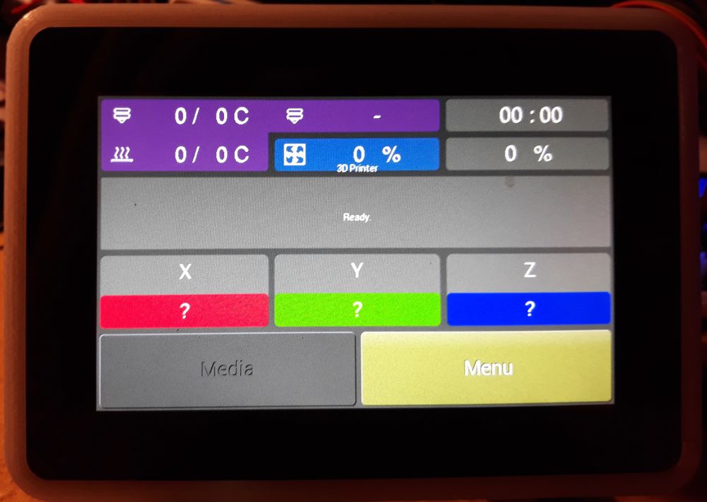
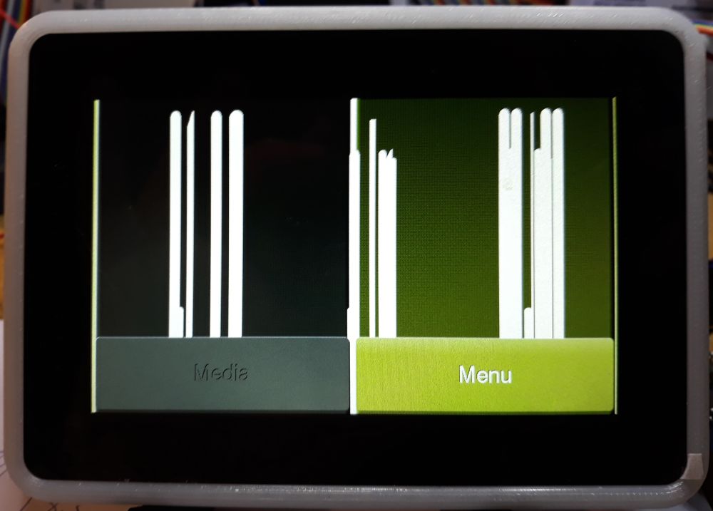
very thanks @GerogeFu for the schemas/specs! but unfortunately, the config exposes in https://github.com/MarlinFirmware/Marlin/pull/17568 is the same config as LCD_ALEPHOBJECTS_CLCD_UI have, which i have test and i get this


if press Media:

if press menu do suind click but nothing in the display
@marciot i also test your octupus examples. all works except the UTF8 example
< offtopic>
~
In file included from /tmp/arduino_build_349971/sketch/src/ftdi_eve_lib/extended/unicode/../../basic/ftdi_basic.h:35:0,
from /tmp/arduino_build_349971/sketch/src/ftdi_eve_lib/extended/unicode/../ftdi_extended.h:26,
from /tmp/arduino_build_349971/sketch/src/ftdi_eve_lib/extended/unicode/western_char_set.cpp:22:
/tmp/arduino_build_349971/sketch/src/ftdi_eve_lib/extended/unicode/../../basic/boards.h:164:8: warning: this use of "defined" may not be portable [-Wexpansion-to-defined]
#if !HAS_RESOLUTION
^~~~
/tmp/arduino_build_349971/sketch/src/ftdi_eve_lib/extended/unicode/../../basic/boards.h:164:8: warning: this use of "defined" may not be portable [-Wexpansion-to-defined]
/tmp/arduino_build_349971/sketch/src/ftdi_eve_lib/extended/unicode/../../basic/boards.h:164:8: warning: this use of "defined" may not be portable [-Wexpansion-to-defined]
In file included from /tmp/arduino_build_349971/sketch/src/ftdi_eve_lib/extended/unicode/../../basic/ftdi_basic.h:35:0,
from /tmp/arduino_build_349971/sketch/src/ftdi_eve_lib/extended/unicode/../ftdi_extended.h:26,
from /tmp/arduino_build_349971/sketch/src/ftdi_eve_lib/extended/unicode/standard_char_set.cpp:22:
/tmp/arduino_build_349971/sketch/src/ftdi_eve_lib/extended/unicode/../../basic/boards.h:164:8: warning: this use of "defined" may not be portable [-Wexpansion-to-defined]
#if !HAS_RESOLUTION
^~~~
/tmp/arduino_build_349971/sketch/src/ftdi_eve_lib/extended/unicode/../../basic/boards.h:164:8: warning: this use of "defined" may not be portable [-Wexpansion-to-defined]
/tmp/arduino_build_349971/sketch/src/ftdi_eve_lib/extended/unicode/../../basic/boards.h:164:8: warning: this use of "defined" may not be portable [-Wexpansion-to-defined]
In file included from /tmp/arduino_build_349971/sketch/src/ftdi_eve_lib/extended/../basic/ftdi_basic.h:35:0,
from /tmp/arduino_build_349971/sketch/src/ftdi_eve_lib/extended/ftdi_extended.h:26,
from /tmp/arduino_build_349971/sketch/src/ftdi_eve_lib/extended/event_loop.cpp:23:
/tmp/arduino_build_349971/sketch/src/ftdi_eve_lib/extended/../basic/boards.h:164:8: warning: this use of "defined" may not be portable [-Wexpansion-to-defined]
#if !HAS_RESOLUTION
^~~~
/tmp/arduino_build_349971/sketch/src/ftdi_eve_lib/extended/../basic/boards.h:164:8: warning: this use of "defined" may not be portable [-Wexpansion-to-defined]
/tmp/arduino_build_349971/sketch/src/ftdi_eve_lib/extended/../basic/boards.h:164:8: warning: this use of "defined" may not be portable [-Wexpansion-to-defined]
In file included from /tmp/arduino_build_349971/sketch/src/ftdi_eve_lib/basic/ftdi_basic.h:35:0,
from /tmp/arduino_build_349971/sketch/src/ftdi_eve_lib/basic/spi.cpp:23:
/tmp/arduino_build_349971/sketch/src/ftdi_eve_lib/basic/boards.h:164:8: warning: this use of "defined" may not be portable [-Wexpansion-to-defined]
#if !HAS_RESOLUTION
^~~~
/tmp/arduino_build_349971/sketch/src/ftdi_eve_lib/basic/boards.h:164:8: warning: this use of "defined" may not be portable [-Wexpansion-to-defined]
/tmp/arduino_build_349971/sketch/src/ftdi_eve_lib/basic/boards.h:164:8: warning: this use of "defined" may not be portable [-Wexpansion-to-defined]
In file included from /tmp/arduino_build_349971/sketch/src/ftdi_eve_lib/basic/ftdi_basic.h:35:0,
from /tmp/arduino_build_349971/sketch/src/ftdi_eve_lib/basic/commands.cpp:23:
/tmp/arduino_build_349971/sketch/src/ftdi_eve_lib/basic/boards.h:164:8: warning: this use of "defined" may not be portable [-Wexpansion-to-defined]
#if !HAS_RESOLUTION
^~~~
/tmp/arduino_build_349971/sketch/src/ftdi_eve_lib/basic/boards.h:164:8: warning: this use of "defined" may not be portable [-Wexpansion-to-defined]
/tmp/arduino_build_349971/sketch/src/ftdi_eve_lib/basic/boards.h:164:8: warning: this use of "defined" may not be portable [-Wexpansion-to-defined]
In file included from /tmp/arduino_build_349971/sketch/src/ftdi_eve_lib/extended/../basic/ftdi_basic.h:35:0,
from /tmp/arduino_build_349971/sketch/src/ftdi_eve_lib/extended/ftdi_extended.h:26,
from /tmp/arduino_build_349971/sketch/src/ftdi_eve_lib/extended/sound_player.cpp:22:
/tmp/arduino_build_349971/sketch/src/ftdi_eve_lib/extended/../basic/boards.h:164:8: warning: this use of "defined" may not be portable [-Wexpansion-to-defined]
#if !HAS_RESOLUTION
^~~~
/tmp/arduino_build_349971/sketch/src/ftdi_eve_lib/extended/../basic/boards.h:164:8: warning: this use of "defined" may not be portable [-Wexpansion-to-defined]
/tmp/arduino_build_349971/sketch/src/ftdi_eve_lib/extended/../basic/boards.h:164:8: warning: this use of "defined" may not be portable [-Wexpansion-to-defined]
In file included from /tmp/arduino_build_349971/sketch/src/ftdi_eve_lib/extended/../basic/ftdi_basic.h:35:0,
from /tmp/arduino_build_349971/sketch/src/ftdi_eve_lib/extended/ftdi_extended.h:26,
from /tmp/arduino_build_349971/sketch/src/ftdi_eve_lib/extended/screen_types.cpp:22:
/tmp/arduino_build_349971/sketch/src/ftdi_eve_lib/extended/../basic/boards.h:164:8: warning: this use of "defined" may not be portable [-Wexpansion-to-defined]
#if !HAS_RESOLUTION
^~~~
/tmp/arduino_build_349971/sketch/src/ftdi_eve_lib/extended/../basic/boards.h:164:8: warning: this use of "defined" may not be portable [-Wexpansion-to-defined]
/tmp/arduino_build_349971/sketch/src/ftdi_eve_lib/extended/../basic/boards.h:164:8: warning: this use of "defined" may not be portable [-Wexpansion-to-defined]
In file included from /tmp/arduino_build_349971/sketch/src/ftdi_eve_lib/extended/../basic/ftdi_basic.h:35:0,
from /tmp/arduino_build_349971/sketch/src/ftdi_eve_lib/extended/ftdi_extended.h:26,
from /tmp/arduino_build_349971/sketch/src/ftdi_eve_lib/extended/command_processor.cpp:22:
/tmp/arduino_build_349971/sketch/src/ftdi_eve_lib/extended/../basic/boards.h:164:8: warning: this use of "defined" may not be portable [-Wexpansion-to-defined]
#if !HAS_RESOLUTION
^~~~
/tmp/arduino_build_349971/sketch/src/ftdi_eve_lib/extended/../basic/boards.h:164:8: warning: this use of "defined" may not be portable [-Wexpansion-to-defined]
/tmp/arduino_build_349971/sketch/src/ftdi_eve_lib/extended/../basic/boards.h:164:8: warning: this use of "defined" may not be portable [-Wexpansion-to-defined]
In file included from /tmp/arduino_build_349971/sketch/src/ftdi_eve_lib/extended/unicode/../../basic/ftdi_basic.h:35:0,
from /tmp/arduino_build_349971/sketch/src/ftdi_eve_lib/extended/unicode/../ftdi_extended.h:26,
from /tmp/arduino_build_349971/sketch/src/ftdi_eve_lib/extended/unicode/font_bitmaps.cpp:22:
/tmp/arduino_build_349971/sketch/src/ftdi_eve_lib/extended/unicode/../../basic/boards.h:164:8: warning: this use of "defined" may not be portable [-Wexpansion-to-defined]
#if !HAS_RESOLUTION
^~~~
/tmp/arduino_build_349971/sketch/src/ftdi_eve_lib/extended/unicode/../../basic/boards.h:164:8: warning: this use of "defined" may not be portable [-Wexpansion-to-defined]
/tmp/arduino_build_349971/sketch/src/ftdi_eve_lib/extended/unicode/../../basic/boards.h:164:8: warning: this use of "defined" may not be portable [-Wexpansion-to-defined]
In file included from /tmp/arduino_build_349971/sketch/src/ftdi_eve_lib/extended/../basic/ftdi_basic.h:35:0,
from /tmp/arduino_build_349971/sketch/src/ftdi_eve_lib/extended/ftdi_extended.h:26,
from /tmp/arduino_build_349971/sketch/src/ftdi_eve_lib/extended/tiny_timer.cpp:22:
/tmp/arduino_build_349971/sketch/src/ftdi_eve_lib/extended/../basic/boards.h:164:8: warning: this use of "defined" may not be portable [-Wexpansion-to-defined]
#if !HAS_RESOLUTION
^~~~
/tmp/arduino_build_349971/sketch/src/ftdi_eve_lib/extended/../basic/boards.h:164:8: warning: this use of "defined" may not be portable [-Wexpansion-to-defined]
/tmp/arduino_build_349971/sketch/src/ftdi_eve_lib/extended/../basic/boards.h:164:8: warning: this use of "defined" may not be portable [-Wexpansion-to-defined]
In file included from /tmp/arduino_build_349971/sketch/src/ftdi_eve_lib/extended/../basic/ftdi_basic.h:35:0,
from /tmp/arduino_build_349971/sketch/src/ftdi_eve_lib/extended/ftdi_extended.h:26,
from /tmp/arduino_build_349971/sketch/src/ftdi_eve_lib/extended/text_box.cpp:22:
/tmp/arduino_build_349971/sketch/src/ftdi_eve_lib/extended/../basic/boards.h:164:8: warning: this use of "defined" may not be portable [-Wexpansion-to-defined]
#if !HAS_RESOLUTION
^~~~
/tmp/arduino_build_349971/sketch/src/ftdi_eve_lib/extended/../basic/boards.h:164:8: warning: this use of "defined" may not be portable [-Wexpansion-to-defined]
/tmp/arduino_build_349971/sketch/src/ftdi_eve_lib/extended/../basic/boards.h:164:8: warning: this use of "defined" may not be portable [-Wexpansion-to-defined]
In file included from /tmp/arduino_build_349971/sketch/src/ftdi_eve_lib/extended/unicode/../../basic/ftdi_basic.h:35:0,
from /tmp/arduino_build_349971/sketch/src/ftdi_eve_lib/extended/unicode/../ftdi_extended.h:26,
from /tmp/arduino_build_349971/sketch/src/ftdi_eve_lib/extended/unicode/unicode.cpp:22:
/tmp/arduino_build_349971/sketch/src/ftdi_eve_lib/extended/unicode/../../basic/boards.h:164:8: warning: this use of "defined" may not be portable [-Wexpansion-to-defined]
#if !HAS_RESOLUTION
^~~~
/tmp/arduino_build_349971/sketch/src/ftdi_eve_lib/extended/unicode/../../basic/boards.h:164:8: warning: this use of "defined" may not be portable [-Wexpansion-to-defined]
/tmp/arduino_build_349971/sketch/src/ftdi_eve_lib/extended/unicode/../../basic/boards.h:164:8: warning: this use of "defined" may not be portable [-Wexpansion-to-defined]
In file included from /tmp/arduino_build_349971/sketch/src/ftdi_eve_lib/extended/unicode/../../basic/ftdi_basic.h:35:0,
from /tmp/arduino_build_349971/sketch/src/ftdi_eve_lib/extended/unicode/../ftdi_extended.h:26,
from /tmp/arduino_build_349971/sketch/src/ftdi_eve_lib/extended/unicode/font_size_t.cpp:22:
/tmp/arduino_build_349971/sketch/src/ftdi_eve_lib/extended/unicode/../../basic/boards.h:164:8: warning: this use of "defined" may not be portable [-Wexpansion-to-defined]
#if !HAS_RESOLUTION
^~~~
/tmp/arduino_build_349971/sketch/src/ftdi_eve_lib/extended/unicode/../../basic/boards.h:164:8: warning: this use of "defined" may not be portable [-Wexpansion-to-defined]
/tmp/arduino_build_349971/sketch/src/ftdi_eve_lib/extended/unicode/../../basic/boards.h:164:8: warning: this use of "defined" may not be portable [-Wexpansion-to-defined]
In file included from /tmp/arduino_build_349971/sketch/src/ftdi_eve_lib/extended/../basic/ftdi_basic.h:35:0,
from /tmp/arduino_build_349971/sketch/src/ftdi_eve_lib/extended/ftdi_extended.h:26,
from /tmp/arduino_build_349971/sketch/src/ftdi_eve_lib/extended/dl_cache.cpp:23:
/tmp/arduino_build_349971/sketch/src/ftdi_eve_lib/extended/../basic/boards.h:164:8: warning: this use of "defined" may not be portable [-Wexpansion-to-defined]
#if !HAS_RESOLUTION
^~~~
/tmp/arduino_build_349971/sketch/src/ftdi_eve_lib/extended/../basic/boards.h:164:8: warning: this use of "defined" may not be portable [-Wexpansion-to-defined]
/tmp/arduino_build_349971/sketch/src/ftdi_eve_lib/extended/../basic/boards.h:164:8: warning: this use of "defined" may not be portable [-Wexpansion-to-defined]
In file included from /tmp/arduino_build_349971/sketch/src/ftdi_eve_lib/basic/../compat.h:20:0,
from /tmp/arduino_build_349971/sketch/src/ftdi_eve_lib/basic/ftdi_basic.h:25,
from /tmp/arduino_build_349971/sketch/src/ftdi_eve_lib/basic/spi.cpp:23:
/tmp/arduino_build_349971/sketch/src/ftdi_eve_lib/basic/../../config.h:101:34: error: 'SPI_SPEED' was not declared in this scope
#define SPI_FREQUENCY 8000000 >> SPI_SPEED
^
/tmp/arduino_build_349971/sketch/src/ftdi_eve_lib/basic/spi.cpp:31:35: note: in expansion of macro 'SPI_FREQUENCY'
SPISettings SPI::spi_settings(SPI_FREQUENCY, MSBFIRST, SPI_MODE0);
^~~
/tmp/arduino_build_349971/sketch/src/ftdi_eve_lib/basic/../../config.h:101:34: note: suggested alternative: 'SPI_MODE0'
#define SPI_FREQUENCY 8000000 >> SPI_SPEED
^
/tmp/arduino_build_349971/sketch/src/ftdi_eve_lib/basic/spi.cpp:31:35: note: in expansion of macro 'SPI_FREQUENCY'
SPISettings SPI::spi_settings(SPI_FREQUENCY, MSBFIRST, SPI_MODE0);
^~~~~
/tmp/arduino_build_349971/sketch/src/ftdi_eve_lib/extended/event_loop.cpp: In static member function 'static uint8_t UIData::get_persistent_data_mask()':
/tmp/arduino_build_349971/sketch/src/ftdi_eve_lib/extended/event_loop.cpp:47:3: warning: missing initializer for member 'UIData::flags_t::
};
^
/tmp/arduino_build_349971/sketch/src/ftdi_eve_lib/extended/event_loop.cpp:47:3: warning: missing initializer for member 'UIData::flags_t::
/tmp/arduino_build_349971/sketch/src/ftdi_eve_lib/extended/event_loop.cpp:47:3: warning: missing initializer for member 'UIData::flags_t::
/tmp/arduino_build_349971/sketch/src/ftdi_eve_lib/extended/event_loop.cpp: In static member function 'static void UIData::reset_persistent_data()':
/tmp/arduino_build_349971/sketch/src/ftdi_eve_lib/extended/event_loop.cpp:62:3: warning: missing initializer for member 'UIData::flags_t::
};
^
/tmp/arduino_build_349971/sketch/src/ftdi_eve_lib/extended/unicode/western_char_set.cpp: In static member function 'static void FTDI::WesternCharSet::load_data(uint32_t)':
/tmp/arduino_build_349971/sketch/src/ftdi_eve_lib/extended/unicode/western_char_set.cpp:342:14: error: 'i' was not declared in this scope
LOOP_L_N(i, 127)
^
/tmp/arduino_build_349971/sketch/src/ftdi_eve_lib/extended/unicode/western_char_set.cpp:342:5: error: 'LOOP_L_N' was not declared in this scope
LOOP_L_N(i, 127)
^~~~
/tmp/arduino_build_349971/sketch/src/ftdi_eve_lib/extended/unicode/western_char_set.cpp: In static member function 'static bool FTDI::WesternCharSet::render_glyph(CommandProcessor*, int&, int&, FTDI::font_size_t, FTDI::utf8_char_t)':
/tmp/arduino_build_349971/sketch/src/ftdi_eve_lib/extended/unicode/western_char_set.cpp:434:34: warning: enumeral and non-enumeral type in conditional expression [-Wextra]
base_char = base_special ? NO_DOT_I : std_char;
~~~^~~~~
~
if comment #define TOUCH_UI_UTF8_WESTERN_CHARSET (and the thig SPI_SPEED) builds ok
tested with the octopus and bugfix-2.0.x ftdi_eve library
but the same config in marlin works ok
< /offtopic>
greetings
sl1pkn07
on 16 Apr 2020
I just read my email , here is the info : https://github.com/FYSETC/TFT81050
@GerogeFu Please post the exact modell of the TFT in use or even better a datasheet for it.
RudolphRiedel
on 16 Apr 2020
This might be working better, this is a lot closer to the 20+ displays I support with my library:
#elif defined(TOUCH_UI_800x480) namespace FTDI { constexpr uint8_t Pclk = 2; constexpr uint8_t Pclkpol = 1; constexpr uint16_t Hsize = 800; constexpr uint16_t Vsize = 480; constexpr uint16_t Vsync0 = 0; constexpr uint16_t Vsync1 = 2; constexpr uint16_t Voffset = 32; constexpr uint16_t Vcycle = 525; constexpr uint16_t Hsync0 = 0; constexpr uint16_t Hsync1 = 48; constexpr uint16_t Hoffset = 88; constexpr uint16_t Hcycle = 928; constexpr uint32_t default_transform_a = 0x0000D8B9; constexpr uint32_t default_transform_b = 0x00000124; constexpr uint32_t default_transform_c = 0xFFE23926; constexpr uint32_t default_transform_d = 0xFFFFFF51; constexpr uint32_t default_transform_e = 0xFFFF7E4F; constexpr uint32_t default_transform_f = 0x01F0AF70; }
Hi, i have test this
~~~patch
diff --git a/Marlin/src/lcd/extui/lib/ftdi_eve_touch_ui/ftdi_eve_lib/basic/resolutions.h b/Marlin/src/lcd/extui/lib/ftdi_eve_touch_ui/ftdi_eve_lib/basic/resolutions.h
index 471530cad..a89009ff7 100644
--- a/Marlin/src/lcd/extui/lib/ftdi_eve_touch_ui/ftdi_eve_lib/basic/resolutions.h
+++ b/Marlin/src/lcd/extui/lib/ftdi_eve_touch_ui/ftdi_eve_lib/basic/resolutions.h
@@ -43,8 +43,8 @@
constexpr uint16_t Vcycle = tv; \
constexpr uint16_t Vsync0 = tvfp - 1; \
constexpr uint16_t Vsync1 = tvfp + tvpw - 1; \
- static_assert(thfp + thb + Hsize == th, "Mismatch in display th"); \
- static_assert(tvfp + tvb + Vsize == tv, "Mismatch in display tv");
- /*static_assert(thfp + thb + Hsize == th, "Mismatch in display th"); \
- static_assert(tvfp + tvb + Vsize == tv, "Mismatch in display tv"); */
#ifdef TOUCH_UI_320x240
namespace FTDI {
@@ -98,20 +98,20 @@
#elif defined(TOUCH_UI_800x480)
namespace FTDI {
- constexpr uint8_t Pclk = 3;
+ constexpr uint8_t Pclk = 2;
constexpr uint8_t Pclkpol = 1;
constexpr uint16_t Hsize = 800;
constexpr uint16_t Vsize = 480;
- constexpr uint16_t th = 1056; // One horizontal line
- constexpr uint16_t thfp = 210; // HS Front porch
- constexpr uint16_t thb = 46; // HS Back porch (blanking)
- constexpr uint16_t thpw = 23; // HS pulse width
- constexpr uint16_t th = 928; // One horizontal line
- constexpr uint16_t thfp = 1; // HS Front porch
- constexpr uint16_t thb = 88; // HS Back porch (blanking)
constexpr uint16_t thpw = 48; // HS pulse width
constexpr uint16_t tv = 525; // Vertical period time
- constexpr uint16_t tvfp = 22; // VS Front porch
- constexpr uint16_t tvb = 23; // VS Back porch (blanking)
- constexpr uint16_t tvpw = 10; // VS pulse width
- constexpr uint16_t tvfp = 1; // VS Front porch
- constexpr uint16_t tvb = 32; // VS Back porch (blanking)
constexpr uint16_t tvpw = 2; // VS pulse width
COMPUTE_REGS_FROM_DATASHEET
~~~
i can't see any visible difference. is a cosmetic change more than funcional change?
greetings
sl1pkn07
on 16 Apr 2020
i can't see any visible difference.
Hmm, okay.
is a cosmetic change more than funcional change?
It is a functional change if the display timings are changed to what they are supposed to be.
This is why I asked for the datasheet of the panel that FYSECT is using.
But then I also do not have this data for the Lulzbot display.
Here have a look at the 800x480 display timings for EVE modules that I gathered so far:
Display_Parameter_800x480.xlsx
The only one really sticking out there is the one from Marlin.
RudolphRiedel
on 16 Apr 2020
About lulzbot tft
https://ohai.lulzbot.com/project/touch-screen-assembly/quiver/
1x [EL-MS0552] Display, 5" BOE VTFT050MRNT01, WVGA TFT with resistive touch panel

but i can't find the datasheet :(.
I've contact with BOEVX for if can send me the datasheet, but i think is not to be success :/
greetings
sl1pkn07
on 16 Apr 2020
In any case, the display parameters look odd to me but they are not exactly wrong or otherwise it would not look as nice as it does.
That is not the real issue.
RudolphRiedel
on 16 Apr 2020
It looks like the function for transferring multiple bytes is missing in the STM32F1 HAL. Someone needs to write it.
It looks like the SPI classes call this write and not transfer.
thinkyhead
on 17 Apr 2020
I even have more basic issues trying to compile with "#define TOUCH_UI_FTDI_EVE" in Configuration.h active:
In file included from Marlin\src\lcd\extui\libftdi_eve_touch_ui\archim2-flash../ftdi_eve_lib/extended/ftdi_extended.h:47:0,
from Marlin\src\lcd\extui\libftdi_eve_touch_ui\archim2-flash../ftdi_eve_lib/ftdi_eve_lib.h:27,
from Marlin\src\lcd\extui\libftdi_eve_touch_ui\archim2-flash\flash_storage.cpp:27:
Marlin\src\lcd\extui\libftdi_eve_touch_ui\archim2-flash../ftdi_eve_lib/extended/sound_list.h: In static member function 'static const char* SoundList::name(uint8_t)':
Marlin\src\lcd\extui\libftdi_eve_touch_ui\archim2-flash../ftdi_eve_lib/extended/sound_list.h:33:29: error: 'pgm_read_ptr_near' was not declared in this scope
return (const char* ) pgm_read_ptr_near(&list[val].name);
My target is STM32F103RC_fysetc and not AVR, so it should not even try to use any of the AVRlibc memory functions.
RudolphRiedel
on 17 Apr 2020
in that error I set this in the HAL.h file
~~~patch
diff --git a/Marlin/src/HAL/STM32F1/HAL.h b/Marlin/src/HAL/STM32F1/HAL.h
index ff42beb92..48c9e8605 100644
--- a/Marlin/src/HAL/STM32F1/HAL.h
+++ b/Marlin/src/HAL/STM32F1/HAL.h
@@ -47,6 +47,9 @@
#include "msc_sd.h"
#endif
+
+#define pgm_read_ptr_near(addr) pgm_read_ptr(addr)
+
// ------------------------
// Defines
// ------------------------
~~~
(if see the parameters in $HOME/.platformio/packages/framework-arduinoststm32-maple/STM32F1/cores/maple/avr/pgmspace.h, all of them uses (addr)
is a simply C&P like do in https://github.com/MarlinFirmware/Marlin/issues/16534#issuecomment-573382828, but only define pgm_read_ptr_near because the rest is already defined
maybe this is why my tft looks wreid in my setup?
greetings
sl1pkn07
on 17 Apr 2020
I changed that pgm_read_ptr_near() in sound_list.h to pgm_read_ptr_far().
That pgm_read_ptr_near() would be wrong even for AVR, or which 64k AVR runs MARLIN?
RudolphRiedel
on 17 Apr 2020
i'm not coder, so idk
greetings
sl1pkn07
on 17 Apr 2020
pgm_read_ptr_near() is for 16 bit adresses
RudolphRiedel
on 17 Apr 2020
Hmm, next issue, the EXP1 header on my board is connected to SPI_2 but it looks like TOUCH_UI_FTDI_EVE is hardcoded to use SPI_1.
RudolphRiedel
on 17 Apr 2020
Okay, I modified spi.cpp and spi.h from Marlin\src\lcd\extui\libftdi_eve_touch_ui\ftdi_eve_lib\basic a little: Marlin_EVE_SPI.zip
I put an instance of the SPIClass into the FTDI namespace that is initialised to the spiPortNumber defined with CLCD_SPI_BUS.
And then I changed a bunch of calls to use EVE_SPI instead of ::SPI.
Oh yes, I also changed it to use .write().
I am just hacking away here, I am in no way confident enough to put this in a PR.
And instancing the class like this will probably only work with the STM32 HAL, with the special version of the STM32 HAL that is included in MARLIN.
The Arduino core from ST is using a different constructor, so is the SAMD core.
I also added this to my pins_FYSETC_CHEETAH.h:
if ENABLED(TOUCH_UI_FTDI_EVE)
#define CLCD_SPI_BUS 2
#define CLCD_MOD_RESET PC9
#define CLCD_SPI_CS PB12
//#define CLCD_USE_SOFT_SPI
#if ENABLED(CLCD_USE_SOFT_SPI)
#define CLCD_SOFT_SPI_MOSI PB15
#define CLCD_SOFT_SPI_MISO PB14
#define CLCD_SOFT_SPI_SCLK PB13
#endif
endif
And at least my Logik Analyzer is showing 8MHz traffic now.
I still need to hook up a display to my board though to see if it works.
RudolphRiedel
on 17 Apr 2020
I tried both an EVE2_50G and an EVE3_50G and they are both displaying the main screen.
Both do flicker a little though.
And I do not have touch yet as both of these use GT911 capacitive touch controllers.
But I have a Marlin Bugfix 2.0x working with a 800x4800 TOUCH_UI_FTDI_EVE display running on a FYSETC Cheetah V1.1 which is a lot closer to the TFT81050 and the FYSETC S6 than using some test-code on an Arduino.
RudolphRiedel
on 17 Apr 2020
Okay, I replaced the timing settings and the flickering is gone.
I activated the GT911 touch controller for the EVE3-50G and now I can use the GUI.
Is TOUCH_UI_FTDI_EVE really supposed to be in working condition?
Well, maybe the issues I have are because I only have the display connected to the board and nothing else.
But a couple of things do look a bit strange.
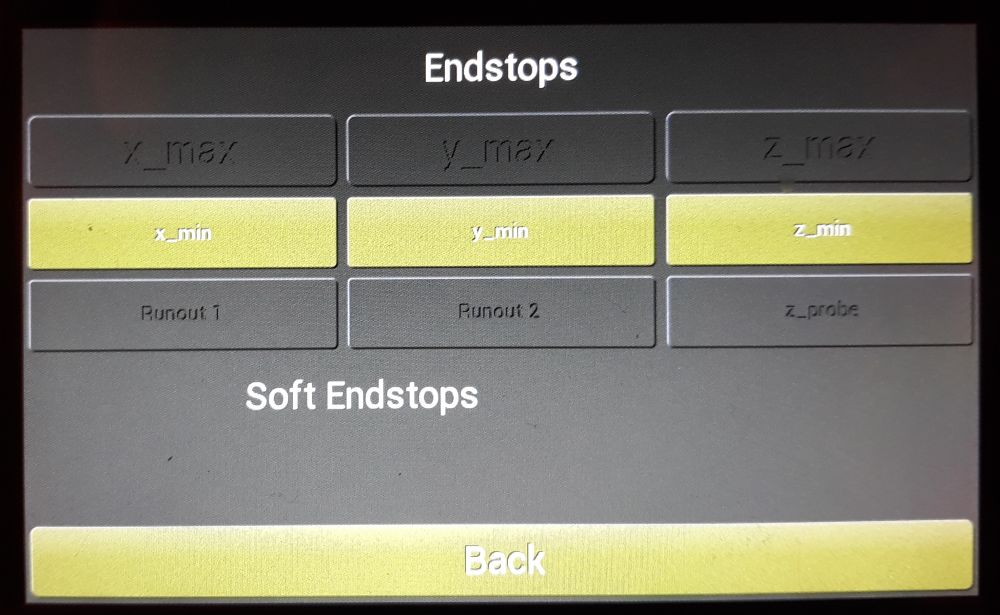
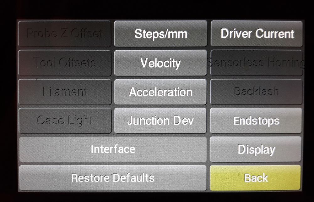
Apart from the wrong font-size for the "Sensorless Homing" button on the "Advanced Settings" menu, using the button "Interface" makes it hang.
I just switched to Software-SPI and that is not working at all, hmm.
RudolphRiedel
on 17 Apr 2020
@RudolphRiedel: Yeah, that looks pretty messed up. The portrait mode with a 800x480 resolution is the only one I regularly test and the only one that is used commercially. This means the other orientation and resolutions often get messed up, which seems to be what happened here.
marciot
on 17 Apr 2020
then only works with hardware SPI? because with you changes, i'm stuck in my first image i posted (deface background, only show 2 buttons)
the SKR E3 DIP uses the hardware SPI for stepers, the SD, and the SPI pinheader
i need set this #define CLCD_SPI_BUS 2 ? what value i need set in my case?
greeetinsg and wreat work!
sl1pkn07
on 17 Apr 2020
It just got a whole lot more interesting:
When switching back to hardware SPI I found out that my FFC cable was defective.
And after I replaced it with a fresh one this is what I get with software SPI.
@marciot
Okay, I check the portrait mode.
RudolphRiedel
on 17 Apr 2020
@RudolphRiedel: Those kinds of artifacts often happen when the FTDI does not have enough time to go through the display list during each scanline. Reducing the display clock rate will solve that problem.
marciot
on 17 Apr 2020
I don't have time right now, but I'll try fixing the landscape mode later. What resolution screen are you using?
marciot
on 17 Apr 2020
@RudolphRiedel: Those kinds of artifacts often happen when the FTDI does not have enough time to go through the display list during each scanline. Reducing the display clock rate will solve that problem.
I never encountered these types of artifacts before.
And apart from that there is not really much happening there, it works with hardware SPI using the exact same display settings.
The screen has 800x480 and so far I am a bit struggeling to find the switch for portrait mode.
RudolphRiedel
on 17 Apr 2020
is in configuration_adv.h
sl1pkn07
on 17 Apr 2020
Yup, found it, still building though...
RudolphRiedel
on 17 Apr 2020
marciot
on 17 Apr 2020
Well, it is in portrait mode now.
But now I have horizontal stripes.
RudolphRiedel
on 17 Apr 2020
HORA HORA HORA!!
rudolph's SPI changes
#define CLCD_SPI_BUS 1 hardware SPI1 (SPI pinheader)
#define TOUCH_UI_PORTRAIT
my adapter seems is a little bit defective (sometimes i get black screen (led works))
sl1pkn07
on 17 Apr 2020
Okay, I switched back to hardware SPI and portrait mode is also not okay.
Practically the same isses as in landscape mode.
Whatever, I switch back to software SPI and try to fix that.
RudolphRiedel
on 17 Apr 2020
Playing with the external TFT SD card (Hardware SPI mode)
https://github.com/sl1pkn07/Marlin/commit/01985ae3584d27b5045c481e1a13d38e03950273
When set SDCARD_CONNECTION LCD, Disable the onboard SD and enable the TFT SD card
problems:
- If boot the board with the TFT SD plugged, the UI is defaced, plug the SD after boot, works normally.
- When plug the SD and unplug it, the speaker sounds "ping" twice (after unplug, plug and unplug the card again sounds "ping" twice again), if plug the SD, pulse the media button, and back to menu, when unplug the SD, sounds "ping" normally
i'm not coder, so i can't fix it with my knowledge
greetings
sl1pkn07
on 18 Apr 2020
SD initialization is one of those things that has needed special attention, because you may have onboard SD that contains EEPROM data, so it needs to be mounted early, or the SD device might be on the LCD, in which case (customarily) the card is mounted during the LCD update (after SPI is initialized), when the SD detect pin state changes. LCD units sometimes get garbled by SD access, so re-init of the screen is also done for some displays on SD mount/unmount. I've been trying to clean up SD card management lately, so the CardReader::manage_media method is current the place to look for SD mounting behavior.
thinkyhead
on 18 Apr 2020
Well, the way I enabled the hardware SPI for the display now was to give it a private instance of the SPIClass.
That seemed to be the natural thing to do since I was focussing on the display and my module here does not even have a SD-card interface.
The more correct way to do this would be to to share an object that Marlin initialised and which also is used to access the SD-card interface - but that rabbit hole really is a little too deep for me.
I know these displays but I am not this familiar with Marlin.
RudolphRiedel
on 18 Apr 2020
I fixed software SPI.
As it turned out, the STM32 is reading MISO too late and therefore reading was shifted by 1 bit.
spi.cpp:
#ifdef CLCD_USE_SOFT_SPI
uint8_t SPI::_soft_spi_xfer (uint8_t spiOutByte) {
uint8_t spiIndex = 0x80;
uint8_t spiInByte = 0;
uint8_t k;
  noInterrupts();
  for (k = 0; k < 8; k++) {  // Output and Read each bit of spiOutByte and spiInByte
    WRITE(CLCD_SOFT_SPI_MOSI, (spiOutByte & spiIndex) ? 1 : 0); // Output MOSI Bit
    WRITE(CLCD_SOFT_SPI_SCLK, 1);   // Pulse Clock
    if (READ(CLCD_SOFT_SPI_MISO)) spiInByte |= spiIndex; // MISO changes on the falling edge of clock, so sample it before
    WRITE(CLCD_SOFT_SPI_SCLK, 0);
    spiIndex >>= 1;
  }
  interrupts();
  return spiInByte;
}
#endif
To my surprise the interface looks and works better with software SPI.
The main menu is displayed correctly, "About Printer" is displayed correctly and the "Interface" from "Advanced Settings" works now as well.
RudolphRiedel
on 18 Apr 2020
Whatever is going on with hardware SPI, it does not seem to be related to the speed.
I went thru the options down to SPI_SIXTEENTH_SPEED, so 8MHz, 4MHz, 2MHz, 1MHz and 0.5MHz.
And the issues are the same, something else gets broken when not using software SPI.
RudolphRiedel
on 18 Apr 2020
Thanks for the patch @RudolphRiedel . yes, works better
Question for everyone : I can assign sofware SPI pins to SD pins (same LCD pins) in a STM32F1 invironment?. the TFT SD works with hardware SPI but not in software SPI
sl1pkn07
on 18 Apr 2020
I am in a STM32F1 enviroment.
As I posted above, I added the definitions to my pins_FYSETC_CHEETAH.h file.
RudolphRiedel
on 18 Apr 2020
sorry, are a general for everyone question, no only for you
sorry :S
I also have questions about SDSS, SS_PIN and LCD_SDSS. i can't see where is provided and whre can use it
sl1pkn07
on 18 Apr 2020
Sorry, I totally misread the question.
RudolphRiedel
on 18 Apr 2020
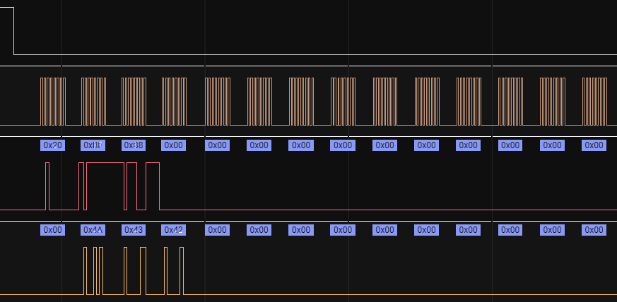
I analyzed Logic-Analyzer traces of the first few seconds with hardware SPI and software SPI.
And the first thing is, I would call this broken in how inefficent it is.
But that is besides the point here.
Up to the first call of this function the SPI traffic is identical:
void CLCD::FontMetrics::load(const uint8_t font) {
static_assert(sizeof(FontMetrics) == 148, "Sizeof font metrics is incorrect");
uint32_t rom_fontroot = mem_read_32(MAP::ROM_FONT_ADDR);
mem_read_bulk(rom_fontroot + 148 * (font - 16), (uint8_t*) this, 148);
}
But then something strange happens.
Hardware Software
MOSI MISO MOSI MISO
0x2F | 0x00 | | 0x2F | 0x00 | read
0xFF | 0x4A | | 0xFF | 0x4A | 0x2fffffc ROM_FONT_ADR
0xFC | 0x43 | | 0xFC | 0x43 |
0x00 | 0x42 | | 0x00 | 0x42 |
0x00 | 0x34 | | 0x00 | 0x34 |
0x00 | 0xB8 | | 0x00 | 0xB8 |
0x00 | 0x20 | | 0x00 | 0x20 |
0x00 | 0x00 | | 0x00 | 0x00 |
0x20 | 0x00 | | 0x20 | 0x00 | read
0xBF | 0x4A | | 0xBF | 0x4A | 0x20bfb8
0xB8 | 0x43 | | 0xB8 | 0x43 |
0x00 | 0x42 | | 0x00 | 0x42 |
0x00 | 0x00 | | 0x00 | 0x00 |
0x00 | 0x00 | | 0x00 | 0x00 |
0x00 | 0x00 | | 0x00 | 0x00 |
0x00 | 0x00 | | 0x00 | 0x00 |
0x78 | 0x00 | | 0x00 | 0x00 |
0x25 | 0x00 | | 0x00 | 0x00 |
0x30 | 0x00 | | 0x00 | 0x00 |
0x00 | 0x00 | | 0x00 | 0x00 |
0xFE | 0x00 | | 0x00 | 0x00 |
0x7F | 0x00 | | 0x00 | 0x00 |
0xF7 | 0x00 | | 0x00 | 0x00 |
0xFF | 0x00 | | 0x00 | 0x00 |
0xFE | 0x00 | | 0x00 | 0x00 |
Look at the first column.
The last entries should all be 0x00 like in the MOSI column for software SPI as this is a mem_read_bulk() for 148 bytes in total.
// Write 4-Byte Address, Read Multiple Bytes
void CLCD::mem_read_bulk (uint32_t reg_address, uint8_t *data, uint16_t len) {
spi_ftdi_select();
spi_read_addr(reg_address);
spi_read_bulk (data, len);
spi_ftdi_deselect();
}
void SPI::spi_read_bulk (void data, uint16_t len) {
uint8_t p = (uint8_t *)data;
#ifndef CLCD_USE_SOFT_SPI
EVE_SPI.write(p, len);
#else
while (len--) *p++ = spi_recv();
#endif
}
inline uint8_t spi_recv() {
  #ifdef CLCD_USE_SOFT_SPI
    return _soft_spi_xfer(0x00);
  #else
    return EVE_SPI.transfer(0x00);
  #endif
};
So this is supposed to send out 148 Zero Bytes in order to read a ROM table from the display.
How does it end up sending out anything else than zeroes?
The data from the display on the MISO line is the same, so this bit-garbage on the MOSI line is only a sympton.
But after that the next command is a read-access to CMD_READ and somehow the result is different now for hardware SPI and software SPI.
RudolphRiedel
on 18 Apr 2020
I am just trying to figure out why it takes forever before the first screen is displayed and found annother bug:
// Write 3-Byte Address, Write 2-Bytes Data
void CLCD::mem_write_16 (uint32_t reg_address, uint16_t data) {
using namespace SPI::least_significant_byte_first;
spi_ftdi_select();
spi_write_addr(reg_address);
spi_write_32(data);
spi_ftdi_deselect();
}
That should be using spi_write_16(data); .
RudolphRiedel
on 18 Apr 2020
@marciot exist a conversor, or something for convert and test regular midi (o tabs) to extui midi sound format?
greetings
sl1pkn07
on 18 Apr 2020
@sl1pkn07: No, there isn't. The FTDI chips are not polyphonic, so playing MIDI files on them would be impossible. For the songs I added to the Marlin code, I looked for Synthesia YouTube videos and manually typed in the notes.
marciot
on 18 Apr 2020
You can also use GCODE to play songs using M300. It currently is hard coded to use the organ instrument. The Imperial March GCODE sounds amazing.
marciot
on 18 Apr 2020
I have inserted a tone in the ending script en my slicer, is played ok through the CR10 stock display speaker. but not sound in the tft speaker, only sound a tone harcoded(?) in the extui when the print is ended ("Tuu tu tu tuuuUUU")
my code is this
~
M300 S2349 P53
M300 S0 P53
M300 S2349 P53
M300 S0 P53
M300 S2349 P53
M300 S0 P53
M300 S2349 P428
M300 S932 P428
M300 S2093 P428
M300 S2349 P107
M300 S0 P214
M300 S2093 P107
M300 S2349 P857
~
sl1pkn07
on 18 Apr 2020
problem when dimm brightness
vid: https://www.youtube.com/watch?v=lBTm6yYQe6k
EDIT: turn up the volume
sl1pkn07
on 19 Apr 2020
I am not sure what the issue is.
I can not tell from the video if dimming is really working or not.
But it works for me, my only complaint would be that I can dim all the way down to no dimming.
Using the slider?
That also works fine for me but then I do use a capacitive touch display.
If that is the issue try using a smal blunt object, like the handle of a plastic tea spoon.
The touch itself is one of the reason why I do not buy resistive touch modules.
The other reason is that the glas front of a cap-touch module results in a sharper image and is easier to clean.
RudolphRiedel
on 19 Apr 2020
the sound when dim. the control is bad because i have controlled with one hand when the display is free on the table xd
sl1pkn07
on 19 Apr 2020
Oh, it makes a sound, yes, that may be a property of the rather low backlight PWM frequency bleeding into the sound.
Go to commands.cpp: void CLCD::init()
There is this line:
mem_write_16(REG::PWM_HZ, 0x00FA);
Change it to:
mem_write_16(REG::PWM_HZ, 10000);
And check if that makes a difference.
That is the maximum value for this register.
While you are there you can also disable the
CommandFifo::reset();
a couple of lines down to speed up the start by 0.4s with no ill effect since this line does nothing usefull at this point in the initialisation.
RudolphRiedel
on 19 Apr 2020
yep. the sound now is inaudible (0x2710) (still exist, but only can make crazy to the dogs)
~~~patch
diff --git a/Marlin/src/lcd/extui/lib/ftdi_eve_touch_ui/ftdi_eve_lib/basic/commands.cpp b/Marlin/src/lcd/extui/lib/ftdi_eve_touch_ui/ftdi_eve_lib/basic/commands.cpp
index 45693eca1..a00fcb1ed 100644
--- a/Marlin/src/lcd/extui/lib/ftdi_eve_touch_ui/ftdi_eve_lib/basic/commands.cpp
+++ b/Marlin/src/lcd/extui/lib/ftdi_eve_touch_ui/ftdi_eve_lib/basic/commands.cpp
@@ -1131,7 +1131,7 @@ void CLCD::init() {
mem_write_8(REG::PCLK, Pclk); // Turns on Clock by setting PCLK Register to the value necessary for the module
- mem_write_16(REG::PWM_HZ, 0x00FA);
mem_write_16(REG::PWM_HZ, 0x2710);
// Turning off dithering seems to help prevent horizontal line artifacts on certain colors
mem_write_8(REG::DITHER, 0);
~~~
tnx!
sl1pkn07
on 19 Apr 2020
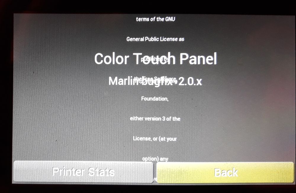
fix for Developer menu trigger
~~~patch
diff --git a/Marlin/src/lcd/extui/lib/ftdi_eve_touch_ui/screens/about_screen.cpp b/Marlin/src/lcd/extui/lib/ftdi_eve_touch_ui/screens/about_screen.cpp
index 5ddc4b650..48b65608f 100644
--- a/Marlin/src/lcd/extui/lib/ftdi_eve_touch_ui/screens/about_screen.cpp
+++ b/Marlin/src/lcd/extui/lib/ftdi_eve_touch_ui/screens/about_screen.cpp
@@ -82,7 +82,7 @@ void AboutScreen::onRedraw(draw_mode_t) {
);
draw_text_box(cmd, FW_VERS_POS, progmem_str(getFirmwareName_str()), OPT_CENTER, font_medium);
draw_text_box(cmd, FW_INFO_POS, about_str, OPT_CENTER, font_medium);
- draw_text_box(cmd, INSET_POS(LICENSE_POS), GET_TEXT_F(MSG_LICENSE), OPT_CENTER, font_tiny);
+ draw_text_box(cmd.tag(3), INSET_POS(LICENSE_POS), GET_TEXT_F(MSG_LICENSE), OPT_CENTER, font_tiny);
cmd.font(font_medium)
.colors(normal_btn)
~~~
sl1pkn07
on 19 Apr 2020
@marciot: Would it be possible to change the screen without actually displaying it?
Something like NEXT_SREEN(screen); instead of GOTO_SCREEN(screen);
The purpose would be to have the next EventLoop::loop() switch to it.
And I still have no idea why hardware SPI fails.
RudolphRiedel
on 19 Apr 2020
Damn, I missed the obvious thing to do:
void SPI::spi_read_bulk (void data, uint16_t len) {
uint8_t p = (uint8_t *)data;
// #ifndef CLCD_USE_SOFT_SPI
// EVE_SPI.write(p, len);
// #else
while (len--) *p++ = spi_recv();
// #endif
}
Hardware SPI works now at 8MHz.
Looks like using SPI.write(p,len) is at least not really an option for STM32F1.
This is the part where it started to fail before:
RudolphRiedel
on 19 Apr 2020
And it works in Landscape mode just fine now.
RudolphRiedel
on 19 Apr 2020
I just added pull-request #17611 for the minor issue that you can turn off the backlight completely in the setup dialog - just to start somewhere with pull-requests...
RudolphRiedel
on 19 Apr 2020
I have inserted a tone in the ending script en my slicer, is played ok through the CR10 stock display speaker. but not sound in the tft speaker, only sound a tone harcoded(?) in the extui when the print is ended ("Tuu tu tu tuuuUUU")
I'm not sure why M300 isn't working, but you can configure the end of print sound by going into Advanced Settings -> Interface -> Sounds. There are several sounds to choose from for print starting, print finished and print failed.
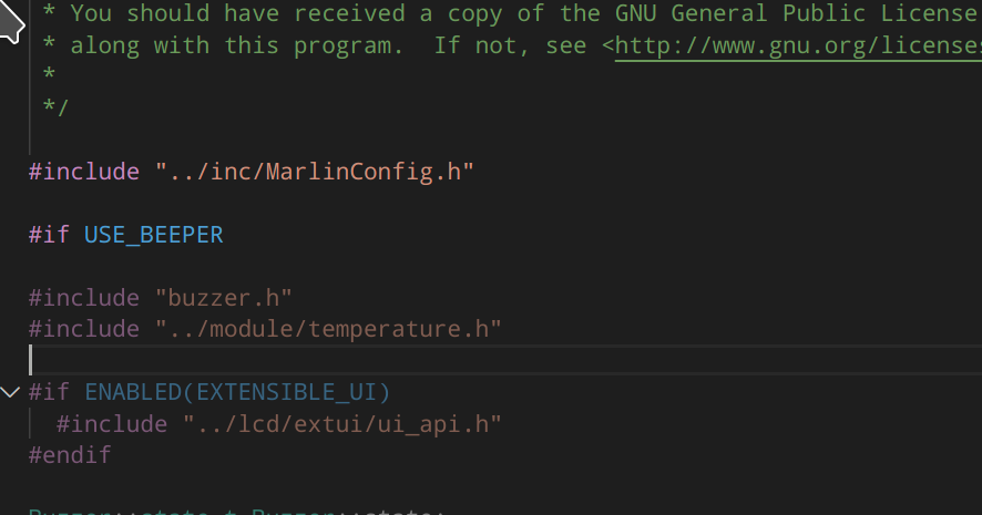
As for why M300 isn't working, here is the bit of code that sends the tone information to the ExtensibleUI:
    if (state.tone.frequency > 0) {
      #if ENABLED(EXTENSIBLE_UI)
        CRITICAL_SECTION_START();
        ExtUI::onPlayTone(state.tone.frequency, state.tone.duration);
        CRITICAL_SECTION_END();
      #elif ENABLED(SPEAKER)
        CRITICAL_SECTION_START();
        ::tone(BEEPER_PIN, state.tone.frequency, state.tone.duration);
        CRITICAL_SECTION_END();
      #else
        on();
      #endif
    }
It would be useful to know which code section is getting compiled. Normally I do this by adding "#error some message" to each of the different choices and seeing which one it actually active.
marciot
on 20 Apr 2020
oh . now know what happen.
all code of buzzer is disabled because I removed the buzzer pin (trying to work SD in software SPI) in the pins_board and because the conditional_post.h does its job
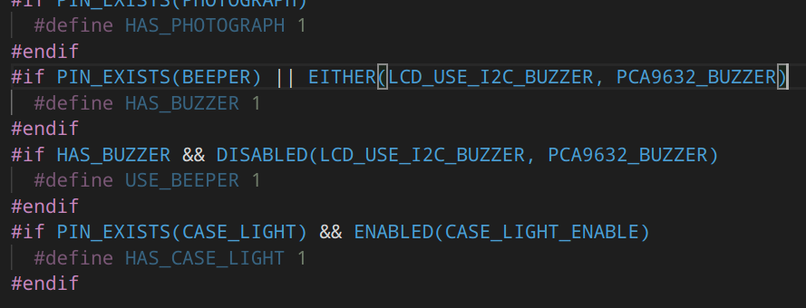
BEEPER_PIN -1 also not works and /dev/null pin no exist xd
I will try tomorrow the hardware SPI (tnx again Rudoplh!)
sl1pkn07
on 20 Apr 2020
done in hardware spi!
now with sound (need disable the sound of print finished because overlap)
note about this line:
void SPI::spi_read_bulk (void data, uint16_t len) {
should be as sis? because without touch is
void SPI::spi_read_bulk (void *data, uint16_t len) {
greetings
sl1pkn07
on 20 Apr 2020
Where does the first line come from?
RudolphRiedel
on 20 Apr 2020
you post
sl1pkn07
on 20 Apr 2020
So yes, this is correct:
void SPI::spi_read_bulk (void data, uint16_t len) {
uint8_t p = (uint8_t *)data;
while (len--) *p++ = spi_recv();
}
RudolphRiedel
on 20 Apr 2020
yes. works with `*data.
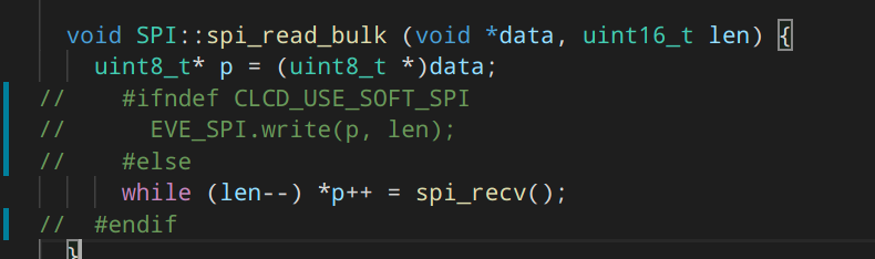
with data
~~
Compiling .pio/build/STM32F103RE_btt/src/src/lcd/extui/lib/ftdi_eve_touch_ui/screens/about_screen.cpp.o
Marlin/src/lcd/extui/lib/ftdi_eve_touch_ui/ftdi_eve_lib/basic/spi.cpp:100:33: error: invalid use of type 'void' in parameter declaration
void SPI::spi_read_bulk (void data, uint16_t len) {
^
Marlin/src/lcd/extui/lib/ftdi_eve_touch_ui/ftdi_eve_lib/basic/spi.cpp:100:51: error: 'void FTDI::SPI::spi_read_bulk(
void SPI::spi_read_bulk (void data, uint16_t len) {
^
~~~
my base is bugfix-2.0.x
sl1pkn07
on 20 Apr 2020
https://github.com/MarlinFirmware/Marlin/pull/17611
when touch the brightness slider, automagic the lights turn off (1)
sl1pkn07
on 20 Apr 2020
Wait, what is going on?
This is how this looks like in the file interface_settings_screen.cpp on my drive:
if(1 > screen_data.InterfaceSettingsScreen.brightness) { /* sanity check to not allow a value of zero */
screen_data.InterfaceSettingsScreen.brightness = 1;
}
Git is happy with that, nothing to commit, nothing to push.
And yet it looks different here:
https://github.com/RudolphRiedel/Marlin/blob/bugfix-2.0.x_extui/Marlin/src/lcd/extui/lib/ftdi_eve_touch_ui/screens/interface_settings_screen.cpp
What the heck?
RudolphRiedel
on 20 Apr 2020
oops i misread the link. sorry i don't know. maybe problems with the branches. i have a lots of problems when rebase the code and do commit --amend instead of rebase --continue
~
if(1 > screen_data.InterfaceSettingsScreen.brightness) { /* sanity check to not allow a value of zero */
screen_data.InterfaceSettingsScreen.brightness = 1;
}
~
do the same. when touch (only touch, no slide) the slider touns off the brightness
and my changes not works also. slide to 0 turns off completely the brightness (is impossible see the UI)
~~~patch
diff --git a/Marlin/src/lcd/extui/lib/ftdi_eve_touch_ui/screens/interface_settings_screen.cpp b/Marlin/src/lcd/extui/lib/ftdi_eve_touch_ui/screens/interface_settings_screen.cpp
index 2fb5478ee..693afad02 100644
--- a/Marlin/src/lcd/extui/lib/ftdi_eve_touch_ui/screens/interface_settings_screen.cpp
+++ b/Marlin/src/lcd/extui/lib/ftdi_eve_touch_ui/screens/interface_settings_screen.cpp
@@ -158,8 +158,9 @@ void InterfaceSettingsScreen::onIdle() {
switch (cmd.track_tag(value)) {
case 2:
screen_data.InterfaceSettingsScreen.brightness = float(value) * 128 / 0xFFFF;
- if (screen_data.InterfaceSettingsScreen.brightness < 1)
- screen_data.InterfaceSettingsScreen.brightness = 1;
- if (screen_data.InterfaceSettingsScreen.brightness < 11) {
- screen_data.InterfaceSettingsScreen.brightness = 11;
- }
CLCD::set_brightness(screen_data.InterfaceSettingsScreen.brightness);
SaveSettingsDialogBox::settingsChanged();
break;
~~~
this works with my tft. the minimum value is 10 (with 10 the light is off) with 11 is possible see the UI cleary
sl1pkn07
on 20 Apr 2020
Nice to see that now more people use FTDI screens.
I have created preheat button in my marlin config but i dont how to make pull request to add it in the firmware online.
Maybe somebody is able to do it with the next the next pull request.
i added this in the temperature_screen.cpp
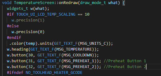
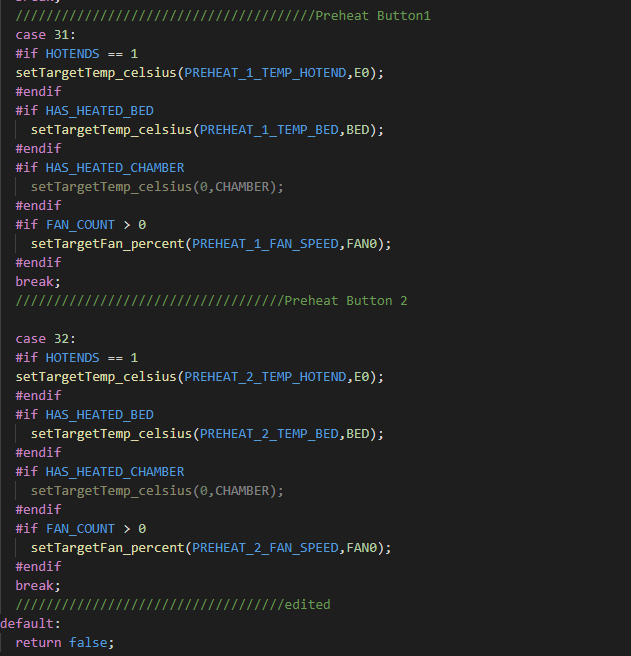
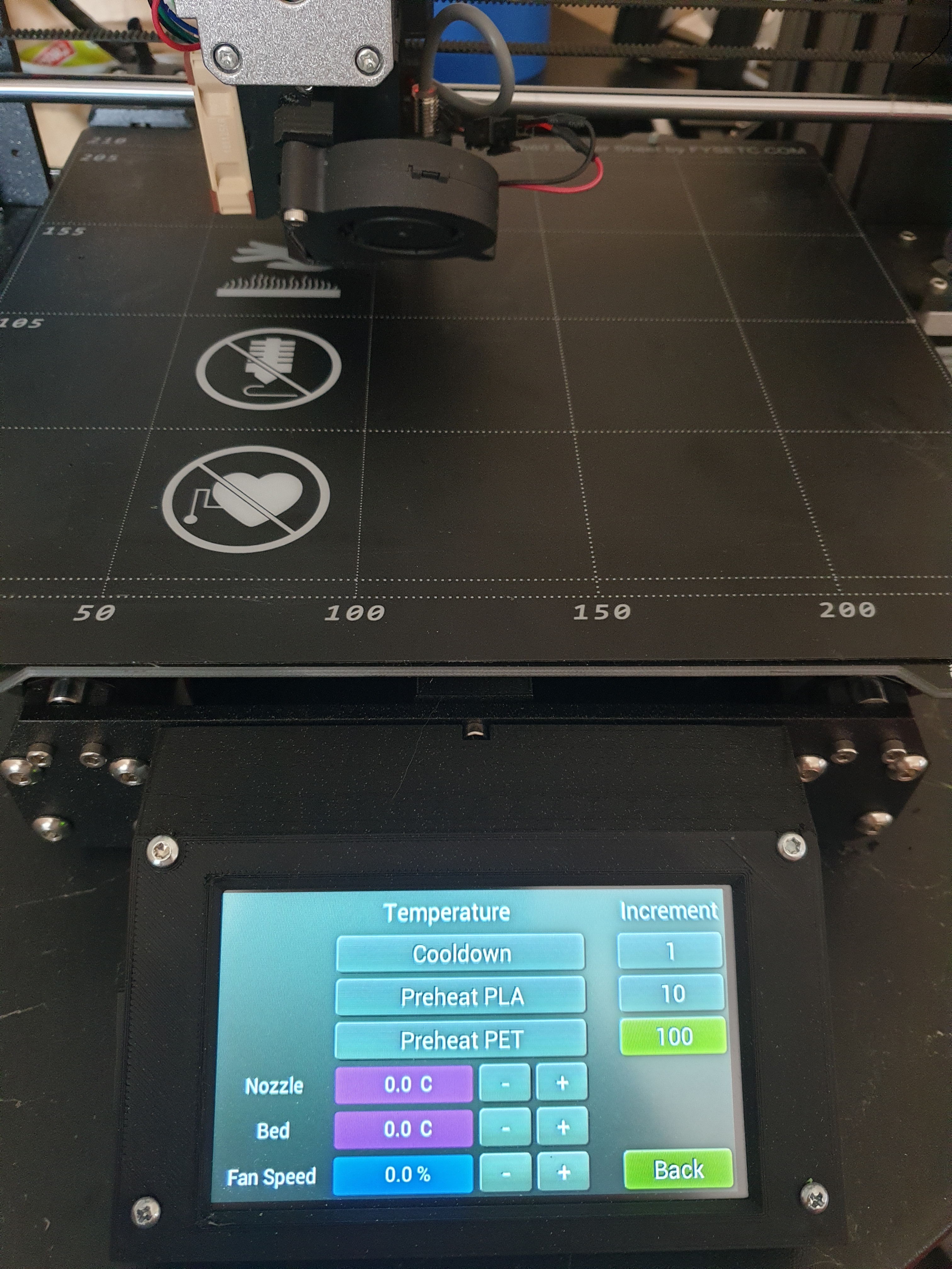
only need to import this file in the screens folder in the ftdi_eve_touc_ui folder
temperature_screen.zip
is somebody plan to use also the mmu2 unit with ftdi screen. i tried to import the mmu2 lcd mmu but i didnt have succes.
TB1405
on 21 Apr 2020
Which display is that? A ME812A-WH50R or a ME813A-WH50C?
After the VM800B I never got annother one of FTDIs own evaluation modules, mostly because they do cost a lot more than the alternatives.
I do have a rather large collection of modules as I am playing longer with EVE than I am 3D printing.
The one I attached to my Fysetc Cheetah Board is an EVE3-50G in a tablet-like casing with a signal converter board that I designed for the control-box of my CR-10.
The EVE3-50G has a BT815 on it which can make use of an external flash memory.
It directly supports UFT-8 with a custom font from this memory.
RudolphRiedel
on 21 Apr 2020
Hi
https://github.com/sl1pkn07/Marlin/commit/5beaad518f8525a6abcc7763b11ee0e5a5e137e9
Bring back support for Mega2560+RAMPS 1.4
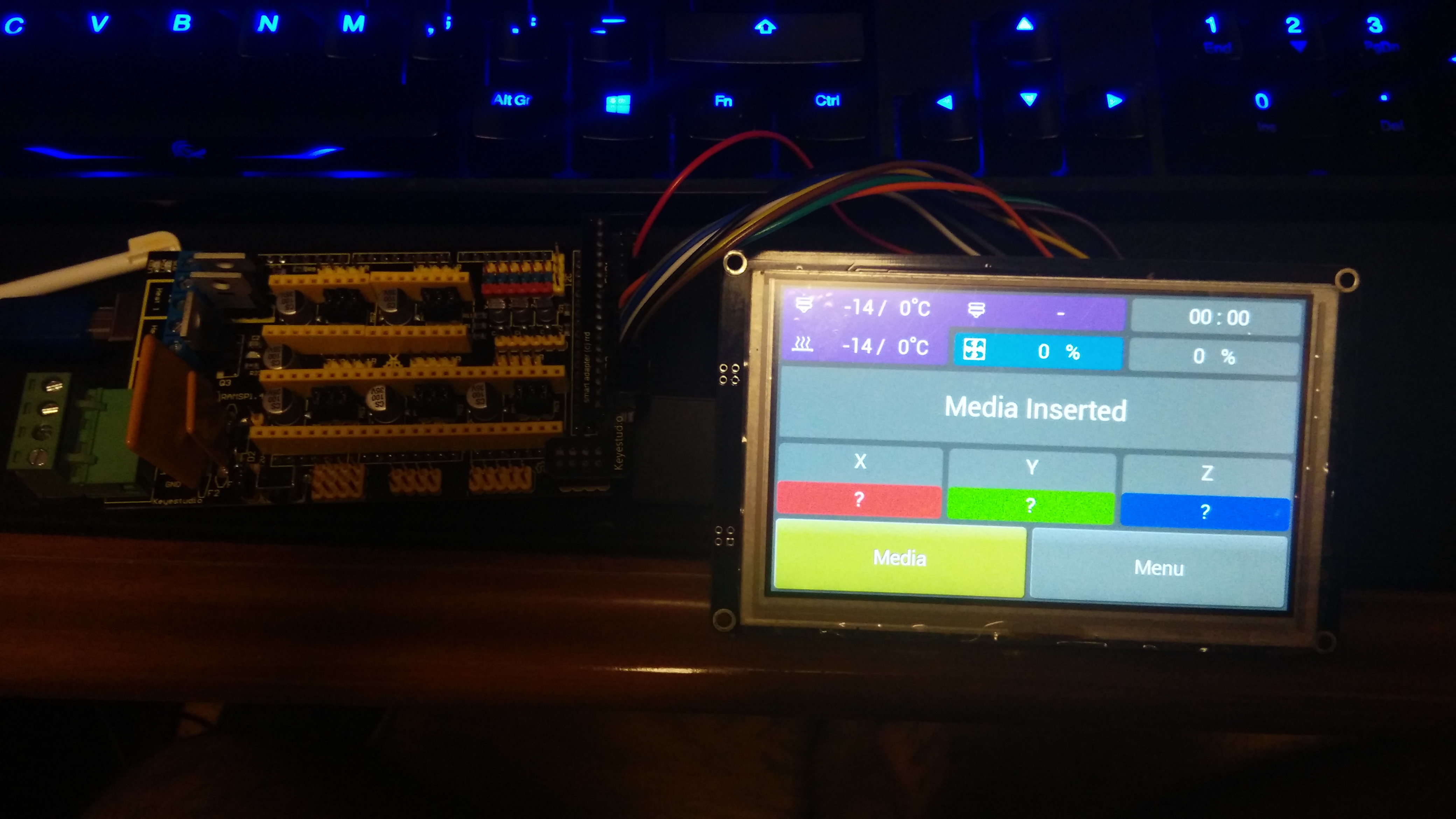
seems the AVR boards don't like the fixes for SoftwareSPI/HardwareSPI in STM32 platforms, so, i've insert the semaphore #ifdef __AVR__ for keep the code working with Mega256+RAMPS1.4 and when the platform is not __AVR__ do the HardwareSPI/SoftwareSPI STM32 changes
Mega2560+RAMPS1.4 needs a custom cable because the EXP2 connector, the +5V pin not exist, so i get it from EXP1 connector
LPC based boards not tested
sl1pkn07
on 22 Apr 2020
seems the AVR boards don't like the fixes for SoftwareSPI/HardwareSPI in STM32 platforms
This is exactly why I put this up for discussion, I know that not all Arduino cores are implemented alike but I certainly do not know all the various Arduino cores - even more so as I usually do not use Arduino at all.
RudolphRiedel
on 22 Apr 2020
And regading SPI and LPC based boards, does the Arduino core for the LPC boards even have hardware SPI support?
I only found this: https://github.com/p3p/pio-framework-arduino-lpc176x
RudolphRiedel
on 22 Apr 2020
Y en el caso de las placas basadas en SPI y LPC, ¿el núcleo Arduino para las placas LPC incluso tiene soporte SPI de hardware?
Solo encontré esto: https://github.com/p3p/pio-framework-arduino-lpc176x
yes, that is used by SKR 1.3, SKR 1.4, MSK Sbase, Panucatt REARM (i use this one), etc.
sl1pkn07
on 22 Apr 2020
What Arduino core does these use then?
The archive I linked only has software-spi but this is what is referenced.
RudolphRiedel
on 22 Apr 2020
after you comment, i'm not sure, maybe @p3p or other dev involved can you reply
is supposed all marlin work with arduino framework...
sl1pkn07
on 22 Apr 2020
Yes, indeed, all boards supported by Marlin use the Arduino framework.
But the implementation of the various Arduino cores is not the same.
RudolphRiedel
on 22 Apr 2020
I have AVR, SAM and should be receiving some SKR boards to play with soon. If you guys want me to review these changes, make a PR against drunken-octopus Marlin and I will review and make necessary adjustments for it to work with those boards.
marciot
on 23 Apr 2020
I am spending the day checking out the various board designs to find those that actually would allow hardware SPI for the TFT.
The list is rather short so far.
Fysetc Cheetah - @GerogeFu good job on this one, I like it even better now :-) I have an idea for a V2.
Fysetc S6
Bigtreetech SKR (EXP2 and no supply)
ARMED V1
Boards like SKR E3 DIP, Einsy Rambo, SKR PRO, Fysetc F6 or the CR-10/Ender 3 ones do not have a full hardware SPI routed to the connector.
So it looks like only a fraction of boards even could benefit from using hardware SPI.
But I am far from done, way too many boards...
RudolphRiedel
on 23 Apr 2020
in the skr e3dip (the mini e3 is more or less the same) i use the ISP port (i think is useless in this board, but now have a new use) near to EXP1 lcd. is a SPI1 port (shared with the onboard TF), so with custom cable is possible use with hardware SPI
raps board (mega2560) also have hardware SPI in the EXP2 connector, but the pin 10 is a NC, (the fysetc S6 the pin 10 is 5V) so need use the pin 10 in the EXP1 connector (or in other alternative point, or weld a wire between EXP2-10 to EXP1-10 in the LCD adapter, or connect directly to EXP3 and EXP4 pins)
sl1pkn07
on 23 Apr 2020
I am spending the day checking out the various board designs to find those that actually would allow hardware SPI for the TFT.
Recall that the FTDI with hardware SPI capability was developed by LulzBot for the Archim 2.0 board. Whether other boards could support it was not really a design consideration, although it's nice to know the software SPI option can be used as a fallback on some of these other boards.
marciot
on 23 Apr 2020
I am only checking the dedicated headers, you can patch a lot of stuff into working.
On the Creality Melzi boards for example I would only need two botch-wires to make it work.
And I was wrong about the Biggtreetech SKR, the EXP2 header is used for the SD-card and the EXP1 header is missing the MOSI pin.
Which header is used on the Archim Board? SC2?
This looks like a header for SD-card but then it also has a micro-sd connector.
SC1 looks like it could be working as well, need to check with the datasheet for the ATSAM3X8.
RudolphRiedel
on 23 Apr 2020
Which header is used on the Archim Board? SC2?
EXP2. The TAZ Pro daisy chains both the display and the USB board off EXP2, as follows:
 *     EXP2:      FTDI:   SD -or- USB:         ULTRA_LCD:
 *      1         MISO    MISO    MISO    -->  MISO
 *      2         SCLK    SCLK    SCLK    -->  SCLK
 *      3         PD_N      -      -      -->  BTN_EN2
 *      4          -      CS_N    CS_N    -->  SD_CSEL
 *      5         CS_N      -      -      -->  BTN_EN1
 *      6         MOSI    MOSI    MOSI    -->  MOSI
 *      7          -      SD_DET  INT     -->  SD_DET
 *      8         RESET     -     RESET   -->  RESET
 *      9         GND     GND     GND     -->  GND
 *     10         5V      5V      5V      -->  KILL [3]
The Archim 2.0 provides 5V on pin 10. This was a special modification we requested from UltiMachine.
marciot
on 23 Apr 2020
The SC1 header would work as well, it has MISO, MOSI and SCK from USART1.
Although at least the V2.2b is one of these with reversed headers.
The MKS Robin E3 could be using hardware SPI as well, interestingly it has SPI1 on the header and SPI2 for the SD-card while the Cheetah has it the other way around.
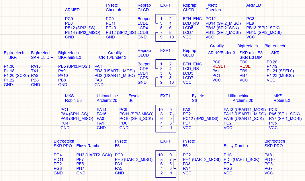
RudolphRiedel
on 23 Apr 2020
Just for clarity, which "Bigtreetech SKR" is this? There's the SKR 1.1, SKR 1.3, SKR 1.4 + Turbo, SKR Pro 1.1, etc...
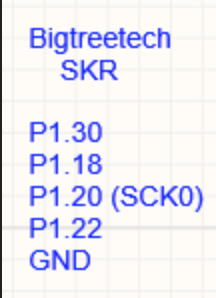
I assume one of the LPC-based SKRs due to the pin numbering, but I wanted to make sure.
thisiskeithb
on 23 Apr 2020
SKR V1.3 and V1.4
https://github.com/bigtreetech/BIGTREETECH-SKR-V1.3
RudolphRiedel
on 23 Apr 2020
Okay, I am done for now, time to finish my PCB.
If you miss one on the list, just ask.
I left out boards like the Duet since it only has 3.3V on the header.
Then I did not check any shield either.
For some boards I could not find anything usefull.
Others like QMP32B or Eryone_STM32 do not seem to exist in meaningfull numbers.
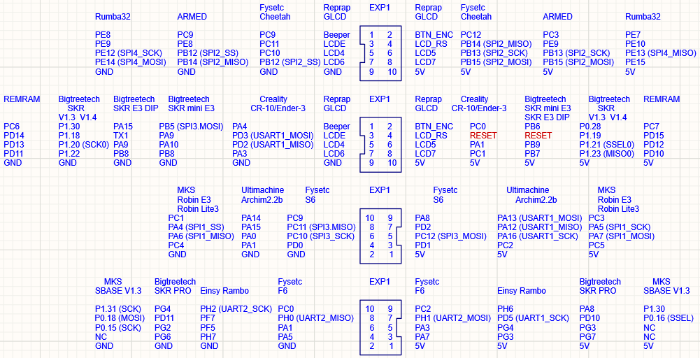
RudolphRiedel
on 23 Apr 2020
for note, in the S6 board, the fysetc TFT is connected directly in the EXP2 without any pin change
sl1pkn07
on 23 Apr 2020
Sure, I forgot about that, for some reason Fysetc designed the TFT for the S6,
that is SPI1 then.
And the conclusion so far is that the most boards that could use hardware SPI are based on STM32.
The one exception is the Archim2 board which is based on ATSAM3X8.
And while the Archim2 even uses the SC2 header for the TFT there still might be some more lines of code necessary to initialise the correct SPI object for this Arduino core.
None of the AVR or LPC boards I looked at would directly allow a hardware SPI for the display.
RudolphRiedel
on 23 Apr 2020
Mega2560+ramps also works
sl1pkn07
on 23 Apr 2020
Does it really? Out of the box on an EXP1 header?
This is btw. what I am up to right now:
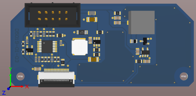
I need to order a couple, test them and if it works out I'll publish all the files.
This allows to connect quite a number of displays in different versions.
From 3.5" to 7", resistive and capacitive touch.
RudolphRiedel
on 24 Apr 2020
Does it really? Out of the box on an EXP1 header?
ramps board (mega2560) also have hardware SPI in the EXP2 connector, but the pin 10 is a NC, (the fysetc S6 the pin 10 is 5V) so need use the pin 10 in the EXP1 connector (or in other alternative point, or weld a wire between EXP2-10 to EXP1-10 in the LCD adapter, or connect directly to EXP3 and EXP4 pins)
https://github.com/MarlinFirmware/Marlin/issues/16628#issuecomment-617511620
why you need use in all situations the EXP1 port?, i think EXP2 can be used for this purpose, and a lot the boards can be compatibles (some AVR at least) the EXP2 have SPI port in it (used for the SD)
sl1pkn07
on 24 Apr 2020
I just limited my research to EXP1, I already reviewed way too many boards today.
In the end I found no common pinout anyways and just made my board 1:1 compatible
with the Fysetc Cheetah.
There is a SPI on the LCD connector, although normally no MISO.
One would think that board designers should be smart enough to put at least SCK and MOSI on there and always on the same pins. Bonus points for using MISO as I/O.
But then half the board designers can not even get the basic pinout right.
RudolphRiedel
on 24 Apr 2020
Some board (for not say "all") have in mind use the RepRapDiscount displays (LCD, encoder, SD, buzzer and reset), both use the scheme with 2 connector EXP1 and EXP2. other boards like creality only one (LCD+encoder), and others his own flex/serial/i2c/whatever connector. or the new MKS E3/D, wich have the RRD ports plus the creality CR10/E3 port
All RRD displays have the same pinout (reverse or not (cog mks cog)) oviously, can use diferent pin in the MCU, but not change the order. so i think all boards with EXP2 (if I can miss the shot) have the SPI hardware pins in it. but the problem (if can call problem) is the pin 10 of the EXT2, with not have 5v volts, only provided in the EXP1, or in EXP2 in some boards (S6 and archim2.0)
I think is better support the RRD EXT2 port than the RDD EXP1 or Creality EXP lcd. at least, only need modify one pin. in the "creality" lcd port, whell, the SKR E3/DIP... bad luck, need use the SPI port and the display port , but dunno, more or less all in here can do it without dificult. in the Cheetah, lucky, only need rearagle the pins order, and in the MKS E3/D , GP. can use both methods. (if i understand the schemes, have SPI1 and SPI2 in both connectors??)
greetings
sl1pkn07
on 24 Apr 2020
Anyways, this shows that some level of tinkering is required to use hardware SPI for the display.
RudolphRiedel
on 24 Apr 2020
I am diffing the latest files to check where I added something else.
commands.cpp:
void CLCD::default_display_orientation() {
  #if FTDI_API_LEVEL >= 810
    // Set the initial display orientation. On the FT810, we use the command
    // processor to do this since it will also update the transform matrices.
    if (FTDI::ftdi_chip >= 810) {
      CommandFifo cmd;
      cmd.setrotate(
          ENABLED(TOUCH_UI_MIRRORED) * 4
        + ENABLED(TOUCH_UI_PORTRAIT) * 2
        + ENABLED(TOUCH_UI_INVERTED) * 1
      );
      cmd.execute();
    }
    else
      TERN_(TOUCH_UI_INVERTED, mem_write_32(REG::ROTATE, 1));
  #elif ANY(TOUCH_UI_PORTRAIT, TOUCH_UI_MIRRORED)
    #error "PORTRAIT or MIRRORED orientation not supported on the FT800."
  #elif ENABLED(TOUCH_UI_INVERTED)
    mem_write_32(REG::ROTATE, 1);
  #endif
}
What exactly does "ENABLED(TOUCH_UI_MIRRORED) * 4" mean?
This is a macro with a macro with a macro with a macro.
Is "ENABLED(TOUCH_UI_MIRRORED)" really meant to be used as expression that either returns One or Zero?
What has been changed in this function did not need to be changed.
And what is wrong in this function is left untouched.
Where did this come from?
RudolphRiedel
on 25 Apr 2020
Where did this come from?
I'm doing various refactors, and you are correct: the ENABLED family of macros all evaluate as 1 or 0 and are usable within code context to check if Marlin features are enabled.
thinkyhead
on 26 Apr 2020
I am trying right now to create a branch for myself that is even with the latest Bugfix 2.0.x but also has the necessary changes to enable me testing it on my board and my display.
And seriously, I have no idea how you guys even do this, instead of doing anything real I am lost in all the changes trying to find these that I did to apply them to the files.
I am six files in and a little demotivated.
Respect.
I need to find a workflow that works, can't spend half a day every time I would like to contribute a couple of lines.
RudolphRiedel
on 26 Apr 2020
Okay, I just pushed a small batch of fixes.
But with some of the other changes lately something else got broken.
The GUI crashes when returning from the menu screen, it stops reacting to touch events.
RudolphRiedel
on 26 Apr 2020
I copied my folder from 2020-04-16 and copied over the files I just changed plus spi.cpp.
As it did not compile I also copied over the latest versions of motion.cpp, motion,h, scara.cpp and scara.h.
It compiles fine and works now.
Now the only question is what change(s) to one of the other files in ftdi_eve_touch_ui broke it.
Edit: the problem is in one of the 70 files in ftdi_eve_touch_ui/screens
RudolphRiedel
on 26 Apr 2020
The issue appears to be with ftdi_eve_lib/compat.h and its TERN_ macro.
When I do not update compat.h and also not update the 17 latest files from screens excluding interface_settings_screen.cpp, the GUI works.
RudolphRiedel
on 26 Apr 2020
I updated every file now except:
ftdi_eve_lib/compat.h
screens/base_screen.cpp
screens/bio_status_screen.cpp
screens/bio_tune_menu.cpp
screens/files_screen.cpp
screens/screens.cpp
screens/screens.h
screens/temperature_screen.cpp
And it still builds and works just fine.
RudolphRiedel
on 26 Apr 2020
So till now it only works with the fysetc Board?
 P-C-R
on 27 Apr 2020
P-C-R
on 27 Apr 2020
depend of your panel and board. can work (probably) with all with RRD and CR10/ender3 connectors. but need custom cable
sl1pkn07
on 27 Apr 2020
Hmm SKR 1.3
P-C-R
on 27 Apr 2020
What would be the wiring Diagramm? Making a custom cable would be no Problem.
Best
P-C-R
on 27 Apr 2020
The Fysetc Cheetah is what I am testing with and since I knew that it supports hardware-SPI I had to make this work as well.
A while ago I tested with the CR-10 board, limited to software-SPI.
The SKR 1.3 has a LPC1768 on it, so hardware SPI might not be quite there yet.
It has two headers:
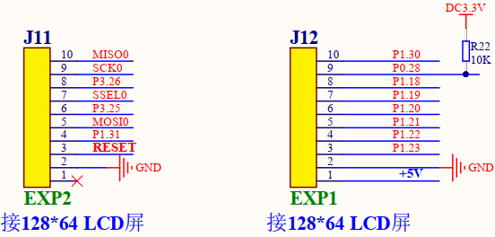
You can either use EXP1 with software-SPI or EXP2 with hardware-SPI.
In case of using EXP2 the header is missing the 5V, I would simply use a patch-wire on the bottom side of the board to fix that.
And then there is the display.
The FT810CB from HAOYU comes with a breakout-board and works with 5V or 3.3V:
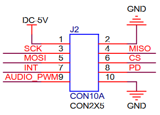
The Fysetc TFT8150 seems to be designed for the EXP2 header and is 3.3V only:
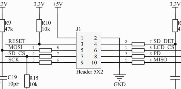
The Lulzbot CLCD2 display has three headers in the schematic and no signal names
next to the pins so I do not cut this out.
Looks like the CLCD2 is intended to be used with 3.3V signals but it might be working
with 5V as well. MISO is not buffered though.
And there is a lot more.
The eval boards from FTDI/BRT usually have pin headers like the VM810C, the VM816C, ME813A-WH50C.
The displays from Newhaven have a pin header as well, one example would be the NHD-5.0-800480FT-CTXL-CTP - but these need 3.3V as well, so an additional voltage regulator is required. And the signals are 3.3V only.
Riverdi has EVE displays as well, RVT50 series or RiTFT50 series for example.
These have a 20pin FFC but Riverdi has a "BREAK OUT BOARD 20" as well.
All the EVE displays from Riverdi need 3.3V and the signals are 3.3V only.
Matrix Orbital has the EVE2 and the EVE3 series, for example the EVE2-50A.
These have a 20pin FFC but Matrix Orbital has a "EVE2-SPI2BBC" as well.
All the EVE displays from Riverdi need 3.3V and the signals are 3.3V only.
The capacitive touch versions are not directly supported in Marlin (yet) as these
use a different touch controller chip - but I have code for that.
The PCB of the EVE3 series also has tinned pads so one could solder wires to it but I have not tried this and also would not recommend this.
Crystalfontz has the CFAF800480E0-050SC which uses a 30pin FFC.
There is the CFA10098 breakout board for it that also has an audio amplifier.
It also requires a 3.3V supply but works with 5V and 3.3V signals.
With most EVE displays available right now you do not get a speaker.
The TFT8150 and the CLCD2 or course have one as these are designed for 3D printers.
Also the FTDI/BRT eval boards usually have speakers.
The little board I designed, see above, has a 20pin FFC for both the Riverdi and the Matrix Orbital modules, it has a level-shifter/buffer to work with 5V or 3.3V signals, it has a 3.3V stepdown converter and a speaker with a driver circuit.
The mounting holes are 65 mm apart, like on the reprap graphics controller, I originally designed this board to use a 3.5" module with the control-box of my CR-10.
Finally a warning is necessary.
Always make sure your board can take the additional load on the power-supply.
A TFT can draw a lot of current, general rule, the bigger it is, the more it draws.
And some TFTs have special features like "sunlight readable", this draw even more current.
For example the Fysetc Cheetah plus EVE3-50G I have on my desk right now with nothing attached but the TFT, no sd-card either.
When I remove the 5V for the TFT it draws around 55mA from 10V and as there is a stepdown converter to 5V on the board, there are about 110mA drawn from this regulator.
When I connect the 5V for the TFT the current from the supply goes up to 220mA, this is at full brightness.
So the 5V regulator has to supply 440mA now.
As I am using a stepdown regulator on my adapter board to convert the 5V to 3.3V this means that the 330mA@5V for the TFT are [email protected].
Using a bigger display and/or a sunlight readable can easily increase that to >[email protected].
Using a smaller display can of course decrease the amount of current necessary.
RudolphRiedel
on 27 Apr 2020
I just realized this, why is the brightness setting for the TFT81050 disabled entirely?
RudolphRiedel
on 27 Apr 2020
Thats is because the sound priblem when dim is a 'no-go' with this display, only fixed when set from 9.9KHz up to 10KHz (PWM_HZ), but not less. and you say can damage the backlit if set over 1KHz (out of backlit chip controller specs), instead of screech teeths, is prefereable disabe it.
or this or need another type of fix, programably or hardware, if is hardware, then FYSETC need fix it, or change the backlit controller chip by DIY (SMD duh)(https://github.com/MarlinFirmware/Marlin/pull/17644#issuecomment-618010274)
The Fysetc TFT8150 seems to be designed for the EXP2 header and is 3.3V only:
mmm then boards like Ramps+mega, this can damage the panel? needs a special converter for each signal?
sl1pkn07
on 27 Apr 2020
You can dim the TFT81050 just fine as long as you keep the frequency below 1kHz.
Only if you go past the 1kHz dimming might shorten the life of the backlight since the soft-start is not working anymore.
You reversed the 10kHz frequency change so dimming is fine.
I would be a good idea for Fysetc to change the backlight driver, yes.
The Fysetc TFT8150 seems to be designed for the EXP2 header and is 3.3V only:
mmm then boards like Ramps+mega, this can damage the panel?
needs a special converter for each signal?
Okay, looks like I need to recheck this.
This is the complete interface for the TFT81050:
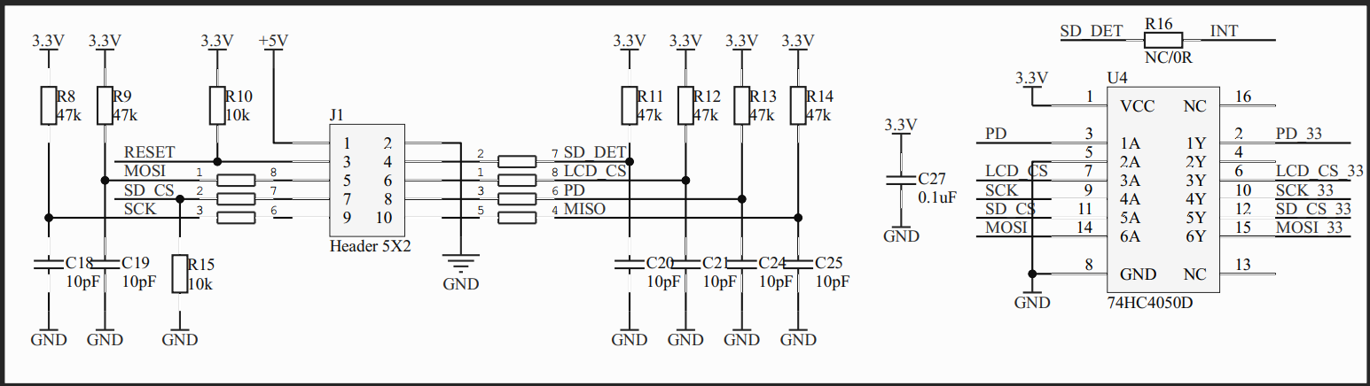
First of, it has the same flaw as the Lulzbot CLCD2, MISO is not buffered, so this 3.3V line is directly connected to the FT810.
Note that spi.cpp has this for software-spi: SET_INPUT_PULLUP(CLCD_SOFT_SPI_MISO);
So when you are using software-SPI you are putting 5V onto the MISO line of the FT810.
Oh yes, the MISO line also is connected to the SD on the TFT81050.
That should lead to less than 100µA due to the pullup-resistor but I do not like this.
Secondly it has quite a number of pullup-resistors to 3.3V.
The lowest one is R10 with 10k on the RESET line, this one serves no purpose at all.
Dangerous? No, at worst case this would mean 170µA between 3.3V and 5V.
Normally the current should be way lower since RESET is no connected to 5V directly.
The other pullups are 47k which means you have 36µA flowing from each pin that is high with a 5V level to 3.3V. Dangerous? Not so much.
So yes, you can use the TFT81050 with a RAMPS+MEGA at 5V but if you are not carefull and switch out MISO with any of the other signal you could end up killing the display.
If MISO would be buffered you would only risc killing the buffer.
If you know what you doing you are probably fine.
But, well, a lot out there seem to be just doing.
Upon closer inspection, someone at Fysetc might need to take a second look at the resistors.
R8/R9/R14 - not sure if these are even necessary, they might be for the SD-slot
R10 - this line is not used, why put a pullup resistor on it?
R15 - this is a pulldown on SD_CS, this really should be a pullup instead, µC Reset -> de-select
R11 - might not be necessary
R12 - this one is correct
R13 - this is a pullup on PD, this really should be a pulldown instead, µC Reset -> power-down
RudolphRiedel
on 27 Apr 2020
very thanks for the advise
@georgefu any thoughts?
@RudolphRiedel for the MISO "error", is possible add a external buffer or pullup, (or whatever need) for fix it (in thle cable or dongle) ?
EDIT: seems with 1N4148 diode can work (thanks to a friend which told me it)
sl1pkn07
on 27 Apr 2020
There are several issues with using a diode.
First is that you will not have a low signal anymore since there is a 5V pullup active in the AVR.
And if you deactivate the pullup you might not have a high signal since AVR need at least 0.6*VCC as a high signal when running on 5V.
This is 3.0V.
Now the 5V may be a bit higher than 5.0V and/or the 3.3V may be a bit lower than 3.3V
Also the output voltage of the FT810 usually is a bit lower than its supply.
If you add a diode to this it will not have much of a forward voltage since there should be almost no current flowing thru it. But this could be the difference from barely working to not working.
Sure, you can try this, maybe your 5V are 4.9V and the 3.3V are 3.4V or the AVR is just as happy with 2.8V as a high signal as it would be with 3.0V.
But this is anything but robust and still might fail when temperatures are a little higher for example.
It sure does protect the pin from getting grilled by a misplaced 5V.
I am using a buffer for this on my board:
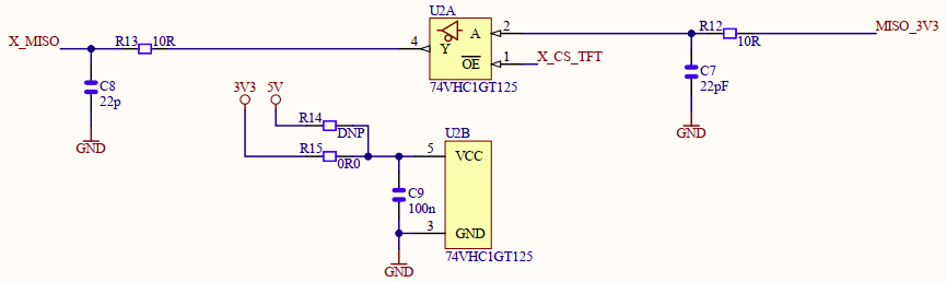
Note that CS is connected to the Output-Enable of this Buffer, if CS is high the output is disabled.
Adding this to the TFT81050 would be more complicated since there is a SD interface on the display as well with its own select pin but a shared MISO line.
RudolphRiedel
on 28 Apr 2020
I checked out all the latest files and it does not build anymore:
Compiling .pio\build\STM32F103RC_fysetc\src\src\lcd\extui\libftdi_eve_touch_ui\screens\bed_mesh_screen.cpp.o
Marlin\src\lcd\extui\libftdi_eve_touch_ui\screens\advanced_settings_menu.cpp: In static member function 'static void AdvancedSettingsMenu::onRedraw(draw_mode_t)':
Marlin\src\lcd\extui\libftdi_eve_touch_ui\screens\advanced_settings_menu.cpp:103:8: error: request for member 'enabled' in 'Language_en::MSG_RESET_BLTOUCH', which is
of non-class type 'const char [14]'
.enabled(EITHER(LIN_ADVANCE, FILAMENT_RUNOUT_SENSOR)
^~~
Marlin\src\lcd\extui\libftdi_eve_touch_ui\screens\advanced_settings_menu.cpp:113:8: error: request for member 'enabled' in 'Language_en::MSG_JUNCTION_DEVIATION', which is of non-class type 'const char [13]'
.enabled(ENABLED(BACKLASH_GCODE))
^~~
Compiling .pio\build\STM32F103RC_fysetc\src\src\lcd\extui\libftdi_eve_touch_ui\screens\bio_advanced_settings.cpp.o
* [.pio\build\STM32F103RC_fysetc\src\src\lcd\extui\libftdi_eve_touch_ui\screens\advanced_settings_menu.cpp.o] Error 1
RudolphRiedel
on 28 Apr 2020
seems MSG_JUNCTION_DEVIATION, MSG_JERK and MSG_OFFSETS_MENU
is not set in ftdi_eve_touch_ui/language/language_en.h
@marciot ?
edit; seems nope :/
sl1pkn07
on 28 Apr 2020
It has to do with the TERN macros. This was something @thinkyhead added to my PR prior to merging. There must be some bad interactions between TERN and GET_TEXT_F.
marciot
on 28 Apr 2020
I really don't get how the TERN macros work. There are no conditionals in them. They apparently work by black magic.
marciot
on 28 Apr 2020
I am glad it is not just me then. :-)
RudolphRiedel
on 28 Apr 2020
It looks like it works by inserting extra commas and using variadic macros. Really peculiar.
marciot
on 28 Apr 2020
I checked out all the latest files and it does not build anymore:
Compiling .pio\build\STM32F103RC_fysetc\src\src\lcd\extui\libftdi_eve_touch_ui\screens\bed_mesh_screen.cpp.o
Marlin\src\lcd\extui\libftdi_eve_touch_ui\screens\advanced_settings_menu.cpp: In static member function 'static void AdvancedSettingsMenu::onRedraw(draw_mode_t)':
Marlin\src\lcd\extui\libftdi_eve_touch_ui\screens\advanced_settings_menu.cpp:103:8: error: request for member 'enabled' in 'Language_en::MSG_RESET_BLTOUCH', which is
of non-class type 'const char [14]'
.enabled(EITHER(LIN_ADVANCE, FILAMENT_RUNOUT_SENSOR)
^~~
Marlin\src\lcd\extui\libftdi_eve_touch_ui\screens\advanced_settings_menu.cpp:113:8: error: request for member 'enabled' in 'Language_en::MSG_JUNCTION_DEVIATION', which is of non-class type 'const char [13]'
.enabled(ENABLED(BACKLASH_GCODE))
^~~
Compiling .pio\build\STM32F103RC_fysetc\src\src\lcd\extui\libftdi_eve_touch_ui\screens\bio_advanced_settings.cpp.o
* [.pio\build\STM32F103RC_fysetc\src\src\lcd\extui\libftdi_eve_touch_ui\screens\advanced_settings_menu.cpp.o] Error 1
Was this fixed? I was looking why those errors keep happening, and it looks like there are few missed closing brackets. And also one #defome, instead of #define.
 MESlammer
on 1 May 2020
MESlammer
on 1 May 2020
Nope, I just checked out all the latest files and it throws more errors at me now.
And I am not really sure what to do about this.
There is this old saying: when in Rome, do it like the Romans.
So reverting the changes that lead to the current issue is not really an option.
On the other hand I am a little irritated by some of the changes, like removal of braces.
And I am irritated by that when I make pull-requests for which I copied existing code to exactly replicate what is alread there, the code that ends up in the repository is changed.
I submitted this:
if (counter == 99) {
#if ENABLED(TOUCH_UI_DEBUG)
SERIAL_ECHO_START();
SERIAL_ECHOLNPAIR("Timeout waiting for resets status, should be 0x00, got ", reset_status);
#endif
}
And now it is this:
if (ENABLED(TOUCH_UI_DEBUG) && counter == 99) {
SERIAL_ECHO_START();
SERIAL_ECHOLNPAIR("Timeout waiting for reset status. Should be 0x00, got ", reset_status);
}
Why? This does not even make sense as now more code is added, or at least the optimizer has to deal with it instead of the pre-processor.
At the same time the code I copied to create this snippet is left untouched.
And a corrected version of this could be this:
#if ENABLED(TOUCH_UI_DEBUG)
if (counter == 99) {
SERIAL_ECHO_START();
SERIAL_ECHOLNPAIR("Timeout waiting for resets status, should be 0x00, got ", reset_status);
}
#endif
So I am really a bit lost here.
RudolphRiedel
on 1 May 2020
On the other hand I am a little irritated by some of the changes, like removal of braces.
And I am irritated by that when I make pull-requests for which I copied existing code to exactly replicate what is alread there, the code that ends up in the repository is changed.
@RudolphRiedel: I've been contributing to Marlin for a few years now and I feel your pain. @thinkyhead maintains Marlin andhas his own way of doing things. I don't always agree (I hate the braces and some of the macros), but I figure that he is the lead maintainer and the onus is on me to adjust. Here is the workflow I've adopted:
- When I want to change something, I make a fresh pull from the upstream repo.
- I then create a branch of "upstream/bugfix-2.0.x" for my change or improvement.
- Once my changes are complete, I push it and make a PR for it.
- At this point, I know @thinkyhead is going to fiddle with it and the changes will not look like what I submitted.
- Until he starts working on it, I may do additional commits (sometimes amending commits) to the PR, but I will not do other work outside of that branch.
- At some point, the PR gets merged into "upstream/bugfix-2.0.x" with @thinkyhead's modifications.
- I can now return to my main devel branch (which does not have any of the changes I made) and merge the changes he made from upstream cleanly.
- I am in sync and I can retest the code and start working on other things.
The key point is, if you submit a PR with changes you made and you keep those changes in your devel repo, you're in for a world of pain trying to merge them together. I've been there.
marciot
on 1 May 2020
I created a PR that fixes some of the issues mentioned in this thread:
https://github.com/MarlinFirmware/Marlin/pull/17825
The GET_TEXT_F problems were caused by mismatched parenthesis. With the new SPI changes, compilation for the Archim (SAM) board was broken. This is because the SPI wrapper class is only present in the HAL for the LPC1768 and STM32F1 and not present for all the other variants. Rather than check for each individually, I decided it is best to use the existence of CLCD_SPI_BUS as the determining factor on whether the wrapper class is used. Thoughts?
marciot
on 1 May 2020
The
GET_TEXT_Fproblems were caused by mismatched parenthesis. With the new SPI changes, compilation for the Archim (SAM) board was broken. This is because the SPI wrapper class is only present in the HAL for the LPC1768 and STM32F1 and not present for all the other variants. Rather than check for each individually, I decided it is best to use the existence of CLCD_SPI_BUS as the determining factor on whether the wrapper class is used. Thoughts?
I gave it a quick test on Arduino Due (they share the same ATSAM3X8E MCU, right?), it works on device, but during compilation there are a lot of warnings like:
Marlin\src\lcd\extui\lib\ftdi_eve_touch_ui\theme\../ftdi_eve_lib/../config.h:60:0: warning: "CLCD_MOD_RESET" redefined
and OTHER_PIN_LAYOUT settings are ignored, so CLCD_MOD_RESET and CLCD_SPI_CS always pins 9 and 10. Am I doing something wrong?
MESlammer
on 1 May 2020
@MESlammer: I updated the PR above with a fix for this. Thank you for reporting this bug!
marciot
on 1 May 2020
should it after this PR also work with SKR1.3 /1.4 than i would try this tomorrow
TB1405
on 1 May 2020
@marciot Thanks, I will rebase when this is thru then.
@TB1405 As you can test with the SKR 1.3/1.4, can you use EXP2+5V and switch to hardware-SPI for the LPC1768? I know EXP2 is on SPI0 with SSEL0 = P0.16, SCK0 = P0.15, MISO0 = P0.17 and MOSI0 = P0.18 - as the schematics says so.
But I have no idea how to configure it, after a quick look over HAL/LPC1768/HAL_SPI.cpp though I am afraid that a simple "SPIClass EVE_SPI(CLCD_SPI_BUS);" with CLCD_SPI_BUS = 0 will not do.
RudolphRiedel
on 1 May 2020
I checked it out but now SPI_FREQUENCY is missing in SPI.cpp.
It was in config.h and I suppose it should be in Configuration_adv.h?
RudolphRiedel
on 3 May 2020
Damn it, it builds now, the firmware is flashing but my Cheetah is dead.
Looks like the 5V regulator is toast, I need to repair the board before I can continue.
RudolphRiedel
on 3 May 2020
Where would be the best place to ask for UI changes and additions? Should i open a new feature request?
Best
P-C-R
on 3 May 2020
I tried to repair my Cheetah today and had to give up.
Long story short, something around the 5V stepdown and the TMC drivers is broken and I blame it on the design that supplies the board when plugging in USB.
@georgefu: Fysetc "owes" me a board - and if it were open source I would have a better chance to repair it.
Anyways, I cut of the 5V regulator and replaced D14 which connects USB_5V to 5V with a 0R0 resistor in order to supply my display from USB.
And as my 5" 800x480 was drawing too much current from the USB, I switched over to a 4.3" with 480x272.
I had to add a new entry to boards.h and also a new entry in resolutions.h.
Then I had to add my new "resolution" to fonts.h to make Marlin compile again.
This concept of separating "boards" and "resolutions" does not really work anymore when you expand the supported displays.
And with my new adapter-board I am using the original LCD-cable from Creality now:

It kind of works but now I have this timeout bug.
RudolphRiedel
on 4 May 2020
The problem with the timeout is this in base_screen.cpp:
void BaseScreen::reset_menu_timeout() {
TERN_(LCD_TIMEOUT_TO_STATUS, last_interaction = millis());
}
This is supposed to do the same as the old version:
void BaseScreen::reset_menu_timeout() {
#if LCD_TIMEOUT_TO_STATUS
last_interaction = millis();
#endif
}
But I really have no idea what TERN_ expands to in the end.
When I roll it back the timeout works just fine.
@thinkyhead I really do not get what the benefit of using these macros is other than obfuscation.
And if you insist on using these, fine, no problem, but please do at least test that your changes are working before committing them.
RudolphRiedel
on 4 May 2020
I tried to repair my Cheetah today and had to give up.
Long story short, something around the 5V stepdown _and_ the TMC drivers is broken and I blame it on the design that supplies the board when plugging in USB.
Sorry to hear this :(
This concept of separating "boards" and "resolutions" does not really work anymore when you expand the supported displays.
Having the resolution tied to the board does not work either, because in the past I've exchanged the TFT panels on boards to get different resolutions than the default. You can't do this is the board type is tied to a particular resolution.
The font size mapping is sort of a PITA, but it is meant to reduce the load on the CPU by determining font sizes at compile-time.
If you have CPU cycles to spare, enable TOUCH_UI_FIT_TEXT and then before drawing any string the code will measure the text and choose a font size that fits the buttons, no matter the display resolution. This is somewhat inefficient though, because it requires the looping through font metrics objects each time a string is drawn. We do use it on our 32-bit boards, with good results.
It kind of works but now I have this timeout bug.
I made a PR with fix for the timeout bug, for the moment, you can set LCD_TIMEOUT_TO_STATUS to 0 in Configuration_adv.h
marciot
on 4 May 2020
Why has pins_FYSETC_CHEETAH.h been modified for TOUCH_UI_FTDI_EVE?
This and any other pins_ file should be completely off-limits for this module.
And the obfuscation with additional layers of defines is not helping at all.
CLCD_MOD_RESET -> BTN_EN1 -> EXPA1_06_PIN -> PC11
CLCD_SPI_CS -> LCD_PINS_RS -> EXPA1_04_PIN -> PB12
CLCD_SOFT_SPI_MOSI -> LCD_PINS_ENABLE -> EXPA1_03_PIN -> PB15
CLCD_SOFT_SPI_MISO -> LCD_PINS_SCK -> EXPA1_07_PIN -> PB14
CLCD_SOFT_SPI_SCLK -> LCD_PINS_D4 -> EXPA1_05_PIN -> PB13
While the resulting pins are correct, the steps in between are all wrong.
-> this is working by chance rather than planned
The first thing is, the footprint of the header is wrong, that is not how the pins are defined for the Cheetah or the RepRap GLCD, that is just the wrong version from Creality.
 *             5V | 1 2 | GND
 *    (MOSI) PB15 | 3 4 | PB12 (LCD_EN)
 *     (SCK) PB13 | 5 6   PC11 (BTN_EN1)
 *  (LCD_RS) PB14 | 7 8 | PC10 (BTN_EN2)
 * (BTN_ENC) PC12 | 9 10| PC9  (BEEPER)
 *                 EXP1
Apart from the incorrect numbering of the pins, BTN_EN1 is connected to PC10 and
BTN_EN2 is connected to PC11 on the Cheetah.
LCD_RS and LCD_EN are the names from FYSETC for the pins in the Cheetah schematic.
If this is taken from the Cheetah schematic, why not use the pin numbers?
Without pins numbers the relation between function, RepRap and µC pin is like this:
CLCD_MOD_RESET -> LCD_PINS_ENABLE -> PC11
CLCD_SPI_CS -> LCD_PINS_D6 -> PB12
CLCD_SOFT_SPI_MOSI -> LCD_PINS_D7 -> PB15
CLCD_SOFT_SPI_MISO -> LCD_PINS_RS  -> PB14
CLCD_SOFT_SPI_SCLK -> LCD_PINS_D5 -> PB13
So how is anyone supposed to look at pin_mappings.h and know what pins are connected?
#define CLCD_MOD_RESET BTN_EN1
BTN_EN1 does not exist for RepRap on EXP1.
#define CLCD_SPI_CS LCD_PINS_RS
LCD_PINS_RS in RepRap Context would be PB14 for the Cheetah.
#define CLCD_SOFT_SPI_MOSI LCD_PINS_ENABLE
LCD_PINS_ENABLE in RepRap is LCDE, that would make it PC11 for the Cheetah.
#define CLCD_SOFT_SPI_MISO LCD_PINS_SCK
LCD_PINS_SCK does not exist for RepRap on EXP1.
#define CLCD_SOFT_SPI_SCLK LCD_PINS_D4
LCD_PINS_D4 in RepRap context would be PC10 for the Cheetah.
Please change this back to the original pins_FYSETC_CHEETAH.h and to whatever other pins_ file has been changed in this context.
And please change this back to my original simple re-mapping for the Cheetah in pin_mappings.h, although a bit modified:
#ifdef CHEETAH_TFT_PINMAP
  #ifndef __MARLIN_FIRMWARE__
    #error "This pin mapping requires Marlin."
  #endif

    #define CLCD_MOD_RESET  PC11
    #define CLCD_SPI_CS     PB12

    //#define CLCD_USE_SOFT_SPI
    #if ENABLED(CLCD_USE_SOFT_SPI)
      #define CLCD_SOFT_SPI_MOSI PB15
      #define CLCD_SOFT_SPI_MISO PB14
      #define CLCD_SOFT_SPI_SCLK PB13
    #else
      #define CLCD_SPI_BUS  2
    #endif
#endif
And the obfuscation with additional layers of defines is not helping at all.
CLCD_MOD_RESET -> BTN_EN1 -> EXPA1_06_PIN -> PC11
CLCD_SPI_CS -> LCD_PINS_RS -> EXPA1_04_PIN -> PB12
CLCD_SOFT_SPI_MOSI -> LCD_PINS_ENABLE -> EXPA1_03_PIN -> PB15
CLCD_SOFT_SPI_MISO -> LCD_PINS_SCK -> EXPA1_07_PIN -> PB14
CLCD_SOFT_SPI_SCLK -> LCD_PINS_D4 -> EXPA1_05_PIN -> PB13
@RudolphRiedel: I was not involved in the creation of pin mappings for FYSETC, so I can't speak to the current config, but I will chime in on why my initial pin_mappings for the Rambo and Archim used the RepRapDiscount pins as an intermediary. The reason for this is that many boards already had a 10 pin connector for the RepRapDiscount display and the AlephObjects display uses the same 10 pin connector for compatibility. AFAIK, it is the only board that uses that connector. By defining my new TFT interface pin out in terms of the old, there was at least a chance that the AlephObjects display could be used on any board with the same ribbon cable as used in the RepRapDiscount display, without having to come up with a new pin map. That was the idea, anyway, whether it works in practice I cannot know.
But yes, if you are using some non-AlephObjects controller, then the pin mapping could count as obfuscation. You certainly do not need to use it for new boards.
marciot
on 6 May 2020
That was not about using the RepRap names per se.
I defined the changes to pin_mappings.h for the Cheetah and it worked just fine.
Only the pin in use for CLCD_MOD_RESET was "in dispute" as I originally chose PC9 for it.
But I agreed to switch over to PC11.
The original defines like LCD_PINS_RS are not active anymore in pins_FYSETC_CHEETAH.h as HAS_SPI_LCD is not true anymore.
So "#define CLCD_SPI_CS PB12" works with the unchanged pins_FYSETC_CHEETAH.h but "#define CLCD_SPI_CS PB12 LCD_PINS_RS" does not.
Also LCD_PINS_RS does not serve any purpose anymore.
Then @sl1pkn07 stepped in and went overboard with it, changed pins_FYSETC_CHEETAH.h and put up annother layer of defines around the pin names - why?
This is unnecessary complex now.
And a bit scary as in the end the pins somehow still are assigned correctly to their function, despite bugs like the wrong numbering and the wrong assignment of BTN_EN1 and BTN_EN2.
RudolphRiedel
on 6 May 2020
first for all apologizes for all disturb
from the schemes

from pic of the board

the position of the pin cover is the same as other E3 board like the stock, BTT E3/DIP, so I flip the pinheader

because in all pin_foo files, the pinout draw use as reference the gap in the plastic in the right side and pin 1 in the upper left
is the same i use to draw the pin connector in the pins_cheetha.h

wich is the same used in BTT_SKR_E3_DIP in first time https://github.com/MarlinFirmware/Marlin/blob/04cea864bcc197a91a162f8cc48cd6588260f8af/Marlin/src/pins/stm32f1/pins_BTT_SKR_E3_DIP.h
now, in the cheetha schemas


so yes, the BTN_EN1 and BTN_EN2 is switched, is my enterely fault. sorry
about use pin alias instead of real pins. is because i follow the pin_mappings.h scheme, with use alias except the CR10 pinout (what CR10 board?). like the pins_BTT_SKR_E3_DIP.h/pins_BTT_SKR_MINI_E3.h (the board i own and can test. i brougth a cheetha 1.1 and MKS E3D boards for add support for the Fysetc TFT81050 display, but both is still in transit)
@marciot @thinkyhead is possible get rid the pins_mappings.h file and do the job in each compatible boards? like the other displays. also is posible reformat the pin scheme structure in all boards?, because all board have his own different structure, wich is difficult use one as reference
greetings
and again, apologizes for all disturb
sl1pkn07
on 7 May 2020
@marciot @thinkyhead is possible get rid the pins_mappings.h file and do the job in each compatible boards? like the other displays. also is posible reformat the pin scheme structure in all boards?, because all board have his own different structure, wich is difficult use one as reference
Of course it is possible. It is not even necessary to get rid of the "pin_mappings.h" file, as it won't come into play unless one of pin mapping constants is defined somewhere. So all you really need to do to implement what you want is to define the various CLCD_* variables in the pin map file for whatever board you are working with.
IMHO, the "pin_mapping.h" file should only be used for generic non-board specific pin maps which make use of the RepRapDiscount pin assignments as an intermediary. Specific setups for boards can and should happen in the pins file for the board itself.
marciot
on 7 May 2020
BTW, I like how you made the ASCII diagram with the gap to show the direction of the connector. Some board schematics define the pin numbers in reverse order, making things very confusing. Usually I have to look at the ground pin to figure out which direction the numbering is going.
marciot
on 7 May 2020
i'm not sure is the pin number order is the correct (ISO(?) standard), i only follow other examples. and yes. draw the connector (if have a ovbiously visual point of reference like this one ) is more concise than only enumerate the pins with names
greetings
sl1pkn07
on 7 May 2020
No, I feel a bit sorry for the noise I made but I felt this needs to be discussed.
sl1pkn07
from the schemes
from pic of the board
Yes, this is correct.
the position of the pin cover is the same as other E3 board like the stock,
BTT E3/DIP, so I flip the pinheader
And this is wrong, The Beeper pin is the top-left one in the board picture.
And the top left pin on all the E3 boards is pin 1.
Just one example from a datasheet for this type of connector:

Note the little triangle, it marks pin 1. You will also find it on the connector.
because in all pin_foo files, the pinout draw use as reference the gap in the plastic
in the right side and pin 1 in the upper left
I won't check all the files now but if this is the case, all the files are wrong.
But if the polarization gap is there that is at least a reference to resolve this.
In any case, documenting it differently as the manufacturer of the board could cause
serious confusion.
wich is the same used in BTT_SKR_E3_DIP in first time https://github.com/MarlinFirmware/Marlin/blob/04cea864bcc197a91a162f8cc48cd6588260f8af/Marlin/src/pins/stm32f1/pins_BTT_SKR_E3_DIP.h
Then this is wrong as well:

This is from the BTT-SKR-E3-DIP schematic.
Okay, this is not really helpfull as the 2x5 is drawn as 1x10, but the pin numbers do match the Fysetc board.
And there is this:

This is from the SKR-mini-E3 schematic:


Excellent, same connector, same pin-assignement, different numbering scheme.
My guess is, Creality messed up.
And as the mini-E3 is a drop-in replacement BTT copied the mistake.
But at least Fysetc did not fell for it.
i'm not sure is the pin number order is the correct (ISO(?) standard),
I am not sure if there is a standard either, I found DIN 41651 though but that might regulate only some special properties for these types of connectors.
But check this:
https://www.digikey.de/products/de/connectors-interconnects/rectangular-connectors-headers-male-pins/314?k=&pkeyword=&sv=0&pv7=2&pv7=3&sf=1&FV=69%7C411897%2C88%7C63986%2C90%7C121326%2C1790%7C9726%2C2024%7C9726%2C-8%7C314%2C2021%7C402177&quantity=&ColumnSort=0&page=1&pageSize=25
3M, TE, Hirose, Samtec, Molex, Harting, etc - they all use the same numbering scheme.
about use pin alias instead of real pins. is because i follow the pin_mappings.h scheme, with use >alias except the CR10 pinout (what CR10 board?).
like the pins_BTT_SKR_E3_DIP.h/pins_BTT_SKR_MINI_E3.h
The CR10 uses the same board as the Ender-3, the CR10S uses a different board.
And I do not object to the alias names per se, I object to use a scheme like this:
CLCD_MOD_RESET -> BTN_EN1 -> EXPA1_06_PIN -> PC11
CLCD_SPI_CS -> LCD_PINS_RS -> EXPA1_04_PIN -> PB12
CLCD_SOFT_SPI_MOSI -> LCD_PINS_ENABLE -> EXPA1_03_PIN -> PB15
CLCD_SOFT_SPI_MISO -> LCD_PINS_SCK -> EXPA1_07_PIN -> PB14
CLCD_SOFT_SPI_SCLK -> LCD_PINS_D4 -> EXPA1_05_PIN -> PB13
What is the benefit of trying to hide that CLCD_MOD_RESET is connected to PC11?
And you added the EXPA1_ defines as additional layer.
If you have this:
define CLCD_MOD_RESET PC11
You can hover with the mouse over CLCD_MOD and it will tell you that it is defined as PC11.
As it is now I can only see that it is defined as BTN_EN1.
And when I look up BTN_EN1 I find it in a different file and that it is defined as EXPA1_06_PIN.
Then I have to check the definition for EXAPA1_06_PIN.
That the pin assignment is currently wrong and that CLCD_MOD should be assigned to BTN_EN2 is an excellent showcase for how important it is to make things simple and not cover it in several layers of defines that are not even used anywhere.
marciot
IMHO, the "pin_mapping.h" file should only be used for generic non-board specific pin
maps which make use of the RepRapDiscount pin assignments as an intermediary.
Specific setups for boards can and should happen in the pins file for the board itself.
Okay, I made my point and you two would like to go in the opposite direction.
Fine, no problem, looks like we are going for the board specific files then.
And if the defines are removed from pin_mappings.h it should be a lot easier to read pins_xxx.h as this is all in one place then.
RudolphRiedel
on 7 May 2020
my point is also get out the file and o the work in each board pin file
about the pin numeration, https://github.com/thinkyhead/Marlin/commit/28008aced08ed187643a19a1931f1b6a060ae3bb. just i say, i only follow the existent code
the use of a tons of alias is because is used in the pins_mapping, but my start point is in the BTT E3 DIP file, wich have setted the EXPA1_FOO alias, the i use it in the other files i modified. in this point seems i make a mistake when i lead my initiative without thinking in other devs. sorry for that
but if i get rid the expa1/2 alias, i can do the same in the rest of pin files wich have seteed on?
Grep Output
~
───╼ grep -R EXPA[1,2]
Marlin/src/pins/lpc1768/pins_BTT_SKR_V1_3.h:#define EXPA1_03_PIN P1_23
Marlin/src/pins/lpc1768/pins_BTT_SKR_V1_3.h:#define EXPA1_04_PIN P1_22
Marlin/src/pins/lpc1768/pins_BTT_SKR_V1_3.h:#define EXPA1_05_PIN P1_21
Marlin/src/pins/lpc1768/pins_BTT_SKR_V1_3.h:#define EXPA1_06_PIN P1_20
Marlin/src/pins/lpc1768/pins_BTT_SKR_V1_3.h:#define EXPA1_07_PIN P1_19
Marlin/src/pins/lpc1768/pins_BTT_SKR_V1_3.h:#define EXPA1_08_PIN P1_18
Marlin/src/pins/lpc1768/pins_BTT_SKR_V1_3.h:#define EXPA1_09_PIN P0_28
Marlin/src/pins/lpc1768/pins_BTT_SKR_V1_3.h:#define EXPA1_10_PIN P1_30
Marlin/src/pins/lpc1768/pins_BTT_SKR_V1_3.h: #define LCD_PINS_RS EXPA1_03_PIN
Marlin/src/pins/lpc1768/pins_BTT_SKR_V1_3.h: #define BTN_EN1 EXPA1_06_PIN
Marlin/src/pins/lpc1768/pins_BTT_SKR_V1_3.h: #define BTN_EN2 EXPA1_04_PIN
Marlin/src/pins/lpc1768/pins_BTT_SKR_V1_3.h: #define BTN_ENC EXPA1_08_PIN
Marlin/src/pins/lpc1768/pins_BTT_SKR_V1_3.h: #define LCD_PINS_ENABLE EXPA1_05_PIN
Marlin/src/pins/lpc1768/pins_BTT_SKR_V1_3.h: #define LCD_PINS_D4 EXPA1_07_PIN
Marlin/src/pins/lpc1768/pins_BTT_SKR_V1_3.h: #define LCD_PINS_RS EXPA1_04_PIN
Marlin/src/pins/lpc1768/pins_BTT_SKR_V1_3.h: #define BTN_EN1 EXPA1_08_PIN
Marlin/src/pins/lpc1768/pins_BTT_SKR_V1_3.h: #define BTN_EN2 EXPA1_06_PIN
Marlin/src/pins/lpc1768/pins_BTT_SKR_V1_3.h: #define BTN_ENC EXPA1_09_PIN // (58) open-drain
Marlin/src/pins/lpc1768/pins_BTT_SKR_V1_3.h: #define LCD_PINS_ENABLE EXPA1_03_PIN
Marlin/src/pins/lpc1768/pins_BTT_SKR_V1_3.h: #define LCD_PINS_D4 EXPA1_05_PIN
Marlin/src/pins/lpc1768/pins_BTT_SKR_V1_3.h: #define LCD_PINS_RS EXPA1_07_PIN
Marlin/src/pins/lpc1768/pins_BTT_SKR_V1_3.h: #define BTN_ENC EXPA1_09_PIN // (58) open-drain
Marlin/src/pins/lpc1768/pins_BTT_SKR_V1_3.h: #define LCD_PINS_ENABLE EXPA1_08_PIN
Marlin/src/pins/lpc1768/pins_BTT_SKR_V1_3.h: #define LCD_PINS_D4 EXPA1_06_PIN
Marlin/src/pins/lpc1768/pins_BTT_SKR_V1_3.h: #define DOGLCD_CS EXPA1_08_PIN
Marlin/src/pins/lpc1768/pins_BTT_SKR_V1_3.h: #define DOGLCD_A0 EXPA1_07_PIN
Marlin/src/pins/lpc1768/pins_BTT_SKR_V1_3.h: #define LCD_RESET_PIN EXPA1_06_PIN // Must be high or open for LCD to operate normally.
Marlin/src/pins/lpc1768/pins_BTT_SKR_V1_3.h: #define RGB_LED_R_PIN EXPA1_05_PIN
Marlin/src/pins/lpc1768/pins_BTT_SKR_V1_3.h: #define RGB_LED_G_PIN EXPA1_04_PIN
Marlin/src/pins/lpc1768/pins_BTT_SKR_V1_3.h: #define RGB_LED_B_PIN EXPA1_03_PIN
Marlin/src/pins/lpc1768/pins_BTT_SKR_V1_3.h: #define NEOPIXEL_PIN EXPA1_05_PIN
Marlin/src/pins/lpc1768/pins_BTT_SKR_V1_3.h: #define DOGLCD_CS EXPA1_05_PIN
Marlin/src/pins/lpc1768/pins_BTT_SKR_V1_3.h: #define DOGLCD_A0 EXPA1_04_PIN
Marlin/src/pins/lpc1768/pins_BTT_SKR_V1_3.h: #define BTN_EN1 EXPA1_08_PIN
Marlin/src/pins/lpc1768/pins_BTT_SKR_V1_3.h: #define BTN_EN2 EXPA1_06_PIN
Marlin/src/pins/lpc1768/pins_BTT_SKR_V1_3.h: #define BTN_ENC EXPA1_09_PIN
Marlin/src/pins/lpc1768/pins_BTT_SKR_V1_3.h: #define DOGLCD_CS EXPA1_04_PIN
Marlin/src/pins/lpc1768/pins_BTT_SKR_V1_3.h: #define DOGLCD_A0 EXPA1_05_PIN
Marlin/src/pins/lpc1768/pins_BTT_SKR_V1_3.h: #define DOGLCD_SCK EXPA1_10_PIN
Marlin/src/pins/lpc1768/pins_BTT_SKR_V1_3.h: #define DOGLCD_MOSI EXPA1_03_PIN
Marlin/src/pins/lpc1768/pins_BTT_SKR_V1_3.h: #define LCD_PINS_D5 EXPA1_05_PIN
Marlin/src/pins/lpc1768/pins_BTT_SKR_V1_3.h: #define LCD_PINS_D6 EXPA1_04_PIN
Marlin/src/pins/lpc1768/pins_BTT_SKR_V1_3.h: #define LCD_PINS_D7 EXPA1_03_PIN
Marlin/src/pins/stm32f1/pins_BTT_SKR_MINI_E3.h:#define EXPA1_03_PIN PB7
Marlin/src/pins/stm32f1/pins_BTT_SKR_MINI_E3.h:#define EXPA1_04_PIN PB8
Marlin/src/pins/stm32f1/pins_BTT_SKR_MINI_E3.h:#define EXPA1_05_PIN PB9
Marlin/src/pins/stm32f1/pins_BTT_SKR_MINI_E3.h:#define EXPA1_06_PIN PA10
Marlin/src/pins/stm32f1/pins_BTT_SKR_MINI_E3.h:#define EXPA1_07_PIN -1
Marlin/src/pins/stm32f1/pins_BTT_SKR_MINI_E3.h:#define EXPA1_08_PIN PA9
Marlin/src/pins/stm32f1/pins_BTT_SKR_MINI_E3.h:#define EXPA1_09_PIN PB6
Marlin/src/pins/stm32f1/pins_BTT_SKR_MINI_E3.h:#define EXPA1_10_PIN PB5
Marlin/src/pins/stm32f1/pins_BTT_SKR_MINI_E3.h: #define BEEPER_PIN EXPA1_10_PIN
Marlin/src/pins/stm32f1/pins_BTT_SKR_MINI_E3.h: #define BTN_ENC EXPA1_09_PIN
Marlin/src/pins/stm32f1/pins_BTT_SKR_MINI_E3.h: #define BTN_EN1 EXPA1_08_PIN
Marlin/src/pins/stm32f1/pins_BTT_SKR_MINI_E3.h: #define BTN_EN2 EXPA1_06_PIN
Marlin/src/pins/stm32f1/pins_BTT_SKR_MINI_E3.h: #define LCD_PINS_RS EXPA1_04_PIN
Marlin/src/pins/stm32f1/pins_BTT_SKR_MINI_E3.h: #define LCD_PINS_ENABLE EXPA1_03_PIN
Marlin/src/pins/stm32f1/pins_BTT_SKR_MINI_E3.h: #define LCD_PINS_D4 EXPA1_05_PIN
Marlin/src/pins/stm32f1/pins_BTT_SKR_MINI_E3.h: #define LCD_PINS_RS EXPA1_05_PIN
Marlin/src/pins/stm32f1/pins_BTT_SKR_MINI_E3.h: #define LCD_PINS_ENABLE EXPA1_09_PIN
Marlin/src/pins/stm32f1/pins_BTT_SKR_MINI_E3.h: #define LCD_PINS_D4 EXPA1_04_PIN
Marlin/src/pins/stm32f1/pins_BTT_SKR_MINI_E3.h: #define LCD_PINS_D5 EXPA1_06_PIN
Marlin/src/pins/stm32f1/pins_BTT_SKR_MINI_E3.h: #define LCD_PINS_D6 EXPA1_08_PIN
Marlin/src/pins/stm32f1/pins_BTT_SKR_MINI_E3.h: #define LCD_PINS_D7 EXPA1_10_PIN
Marlin/src/pins/stm32f1/pins_BTT_SKR_MINI_E3.h: #define BTN_ENC EXPA1_09_PIN
Marlin/src/pins/stm32f1/pins_BTT_SKR_MINI_E3.h: #define BTN_EN1 EXPA1_08_PIN
Marlin/src/pins/stm32f1/pins_BTT_SKR_MINI_E3.h: #define BTN_EN2 EXPA1_06_PIN
Marlin/src/pins/stm32f1/pins_BTT_SKR_MINI_E3.h: #define DOGLCD_CS EXPA1_04_PIN
Marlin/src/pins/stm32f1/pins_BTT_SKR_MINI_E3.h: #define DOGLCD_A0 EXPA1_05_PIN
Marlin/src/pins/stm32f1/pins_BTT_SKR_MINI_E3.h: #define DOGLCD_SCK EXPA1_10_PIN
Marlin/src/pins/stm32f1/pins_BTT_SKR_MINI_E3.h: #define DOGLCD_MOSI EXPA1_03_PIN
Marlin/src/pins/stm32f1/pins_BTT_SKR_MINI_E3.h: #define BEEPER_PIN EXPA1_09_PIN
Marlin/src/pins/stm32f1/pins_BTT_SKR_MINI_E3.h: #define BTN_EN1 EXPA1_08_PIN
Marlin/src/pins/stm32f1/pins_BTT_SKR_MINI_E3.h: #define LCD_PINS_RS EXPA1_04_PIN
Marlin/src/pins/stm32f1/pins_BTT_SKR_MINI_E3.h: #define LCD_PINS_ENABLE EXPA1_03_PIN
Marlin/src/pins/stm32f1/pins_BTT_SKR_MINI_E3.h: #define LCD_PINS_D4 EXPA1_05_PIN
Marlin/src/pins/stm32f1/pins_BTT_SKR_MINI_E3.h: #define SD_DETECT_PIN EXPA1_10_PIN
Marlin/src/pins/stm32f1/pins_BTT_SKR_MINI_E3.h: #define SS_PIN EXPA1_06_PIN
Marlin/src/pins/stm32f1/pins_BTT_SKR_E3_DIP.h:#define EXPA1_03_PIN PB7
Marlin/src/pins/stm32f1/pins_BTT_SKR_E3_DIP.h:#define EXPA1_04_PIN PB8
Marlin/src/pins/stm32f1/pins_BTT_SKR_E3_DIP.h:#define EXPA1_05_PIN PB9
Marlin/src/pins/stm32f1/pins_BTT_SKR_E3_DIP.h:#define EXPA1_06_PIN PA10
Marlin/src/pins/stm32f1/pins_BTT_SKR_E3_DIP.h:#define EXPA1_07_PIN -1
Marlin/src/pins/stm32f1/pins_BTT_SKR_E3_DIP.h:#define EXPA1_08_PIN PA9
Marlin/src/pins/stm32f1/pins_BTT_SKR_E3_DIP.h:#define EXPA1_09_PIN PB6
Marlin/src/pins/stm32f1/pins_BTT_SKR_E3_DIP.h:#define EXPA1_10_PIN PA15
Marlin/src/pins/stm32f1/pins_BTT_SKR_E3_DIP.h: #define BEEPER_PIN EXPA1_10_PIN
Marlin/src/pins/stm32f1/pins_BTT_SKR_E3_DIP.h: #define BTN_ENC EXPA1_09_PIN
Marlin/src/pins/stm32f1/pins_BTT_SKR_E3_DIP.h: #define BTN_EN1 EXPA1_08_PIN
Marlin/src/pins/stm32f1/pins_BTT_SKR_E3_DIP.h: #define BTN_EN2 EXPA1_06_PIN
Marlin/src/pins/stm32f1/pins_BTT_SKR_E3_DIP.h: #define LCD_PINS_RS EXPA1_04_PIN
Marlin/src/pins/stm32f1/pins_BTT_SKR_E3_DIP.h: #define LCD_PINS_ENABLE EXPA1_03_PIN
Marlin/src/pins/stm32f1/pins_BTT_SKR_E3_DIP.h: #define LCD_PINS_D4 EXPA1_05_PIN
Marlin/src/pins/stm32f1/pins_BTT_SKR_E3_DIP.h: #define LCD_PINS_RS EXPA1_05_PIN
Marlin/src/pins/stm32f1/pins_BTT_SKR_E3_DIP.h: #define LCD_PINS_ENABLE EXPA1_09_PIN
Marlin/src/pins/stm32f1/pins_BTT_SKR_E3_DIP.h: #define LCD_PINS_D4 EXPA1_04_PIN
Marlin/src/pins/stm32f1/pins_BTT_SKR_E3_DIP.h: #define LCD_PINS_D5 EXPA1_06_PIN
Marlin/src/pins/stm32f1/pins_BTT_SKR_E3_DIP.h: #define LCD_PINS_D6 EXPA1_08_PIN
Marlin/src/pins/stm32f1/pins_BTT_SKR_E3_DIP.h: #define LCD_PINS_D7 EXPA1_10_PIN
Marlin/src/pins/stm32f1/pins_BTT_SKR_E3_DIP.h: #define BTN_ENC EXPA1_09_PIN
Marlin/src/pins/stm32f1/pins_BTT_SKR_E3_DIP.h: #define BTN_EN1 EXPA1_08_PIN
Marlin/src/pins/stm32f1/pins_BTT_SKR_E3_DIP.h: #define BTN_EN2 EXPA1_06_PIN
Marlin/src/pins/stm32f1/pins_BTT_SKR_E3_DIP.h: #define DOGLCD_CS EXPA1_04_PIN
Marlin/src/pins/stm32f1/pins_BTT_SKR_E3_DIP.h: #define DOGLCD_A0 EXPA1_05_PIN
Marlin/src/pins/stm32f1/pins_BTT_SKR_E3_DIP.h: #define DOGLCD_SCK EXPA1_10_PIN
Marlin/src/pins/stm32f1/pins_BTT_SKR_E3_DIP.h: #define DOGLCD_MOSI EXPA1_03_PIN
Marlin/src/pins/stm32f1/pins_BTT_SKR_E3_DIP.h: #define BEEPER_PIN EXPA1_09_PIN
Marlin/src/pins/stm32f1/pins_BTT_SKR_E3_DIP.h: #define BTN_EN1 EXPA1_08_PIN
Marlin/src/pins/stm32f1/pins_BTT_SKR_E3_DIP.h: #define LCD_PINS_RS EXPA1_04_PIN
Marlin/src/pins/stm32f1/pins_BTT_SKR_E3_DIP.h: #define SD_DETECT_PIN EXPA1_10_PIN
Marlin/src/pins/stm32f1/pins_BTT_SKR_E3_DIP.h: #define SS_PIN EXPA1_06_PIN
Marlin/src/pins/stm32f1/pins_FYSETC_CHEETAH.h:#define EXPA1_03_PIN PB15
Marlin/src/pins/stm32f1/pins_FYSETC_CHEETAH.h:#define EXPA1_04_PIN PB12
Marlin/src/pins/stm32f1/pins_FYSETC_CHEETAH.h:#define EXPA1_05_PIN PB13
Marlin/src/pins/stm32f1/pins_FYSETC_CHEETAH.h:#define EXPA1_06_PIN PC11
Marlin/src/pins/stm32f1/pins_FYSETC_CHEETAH.h:#define EXPA1_07_PIN PB14
Marlin/src/pins/stm32f1/pins_FYSETC_CHEETAH.h:#define EXPA1_08_PIN PC10
Marlin/src/pins/stm32f1/pins_FYSETC_CHEETAH.h:#define EXPA1_09_PIN PC12
Marlin/src/pins/stm32f1/pins_FYSETC_CHEETAH.h:#define EXPA1_10_PIN PC9
Marlin/src/pins/stm32f1/pins_FYSETC_CHEETAH.h: #define BEEPER_PIN EXPA1_10_PIN
Marlin/src/pins/stm32f1/pins_FYSETC_CHEETAH.h: #define DOGLCD_A0 EXPA1_07_PIN
Marlin/src/pins/stm32f1/pins_FYSETC_CHEETAH.h: #define DOGLCD_CS EXPA1_04_PIN
Marlin/src/pins/stm32f1/pins_FYSETC_CHEETAH.h: #define DOGLCD_SCK EXPA1_05_PIN
Marlin/src/pins/stm32f1/pins_FYSETC_CHEETAH.h: #define DOGLCD_MOSI EXPA1_03_PIN
Marlin/src/pins/stm32f1/pins_FYSETC_CHEETAH.h: #define LCD_PINS_RS EXPA1_04_PIN // CS -- SOFT SPI for ENDER3 LCD
Marlin/src/pins/stm32f1/pins_FYSETC_CHEETAH.h: #define LCD_PINS_D4 EXPA1_05_PIN // SCLK
Marlin/src/pins/stm32f1/pins_FYSETC_CHEETAH.h: #define LCD_PINS_ENABLE EXPA1_03_PIN // DATA MOSI
Marlin/src/pins/stm32f1/pins_FYSETC_CHEETAH.h: #define BTN_EN1 EXPA1_06_PIN
Marlin/src/pins/stm32f1/pins_FYSETC_CHEETAH.h: #define BTN_EN2 EXPA1_08_PIN
Marlin/src/pins/stm32f1/pins_FYSETC_CHEETAH.h: #define BTN_ENC EXPA1_09_PIN
Marlin/src/pins/stm32f1/pins_FYSETC_CHEETAH.h: #define BEEPER_PIN EXPA1_10_PIN
Marlin/src/pins/stm32f1/pins_FYSETC_CHEETAH.h: #define BTN_EN1 EXPA1_06_PIN
Marlin/src/pins/stm32f1/pins_FYSETC_CHEETAH.h: #define LCD_PINS_RS EXPA1_04_PIN
Marlin/src/pins/stm32f1/pins_FYSETC_CHEETAH.h: #define LCD_PINS_ENABLE EXPA1_03_PIN
Marlin/src/pins/stm32f1/pins_FYSETC_CHEETAH.h: #define LCD_PINS_SCK EXPA1_07_PIN
Marlin/src/pins/stm32f1/pins_FYSETC_CHEETAH.h: #define LCD_PINS_D4 EXPA1_05_PIN
Marlin/src/pins/lpc1768/pins_BTT_SKR_V1_3.h:#define EXPA2_03_PIN -1
Marlin/src/pins/lpc1768/pins_BTT_SKR_V1_3.h:#define EXPA2_04_PIN P1_31
Marlin/src/pins/lpc1768/pins_BTT_SKR_V1_3.h:#define EXPA2_05_PIN P0_18
Marlin/src/pins/lpc1768/pins_BTT_SKR_V1_3.h:#define EXPA2_06_PIN P3_25
Marlin/src/pins/lpc1768/pins_BTT_SKR_V1_3.h:#define EXPA2_07_PIN P0_16
Marlin/src/pins/lpc1768/pins_BTT_SKR_V1_3.h:#define EXPA2_08_PIN P3_26
Marlin/src/pins/lpc1768/pins_BTT_SKR_V1_3.h:#define EXPA2_09_PIN P0_15
Marlin/src/pins/lpc1768/pins_BTT_SKR_V1_3.h:#define EXPA2_10_PIN P0_17
Marlin/src/pins/lpc1768/pins_BTT_SKR_V1_3.h: #define BTN_EN1 EXPA2_08_PIN // (31) J3-2 & AUX-4
Marlin/src/pins/lpc1768/pins_BTT_SKR_V1_3.h: #define BTN_EN2 EXPA2_06_PIN // (33) J3-4 & AUX-4
Marlin/src/pins/lpc1768/pins_BTT_SKR_V1_3.h: #define LCD_SDSS EXPA2_07_PIN // (16) J3-7 & AUX-4
Marlin/src/pins/lpc1768/pins_BTT_SKR_V1_3.h: #define SD_DETECT_PIN EXPA2_04_PIN // (49) (NOT 5V tolerant)
Marlin/src/pins/lpc1768/pins_BTT_SKR_V1_3.h: #define DOGLCD_SCK EXPA2_09_PIN
Marlin/src/pins/lpc1768/pins_BTT_SKR_V1_3.h: #define DOGLCD_MOSI EXPA2_05_PIN
Marlin/src/pins/lpc1768/pins_BTT_SKR_V1_3.h: #define DOGLCD_SCK EXPA2_09_PIN
Marlin/src/pins/lpc1768/pins_BTT_SKR_V1_3.h: #define DOGLCD_MOSI EXPA2_05_PIN
Marlin/src/pins/lpc1768/pins_BTT_SKR_V1_3.h: #define SS_PIN EXPA2_07_PIN
~
@thinkyhead, is ok if remove the set up EXPA alias and set the pin name instead?
greetings
sl1pkn07
on 7 May 2020
Woa, okay, I would say you got me good there.
I do not have to like it to go with the flow. :-)
RudolphRiedel
on 7 May 2020
is ok if remove the set up EXPA alias and set the pin name instead?
Yes.
The point of any of these indirect header plug mappings is to make it easier to map different common display connectors to the EXP headers. However, in practice it doesn't always look as pretty or map as cleanly as we would like.
Can you imagine trying to make a single pins/pins_lcd.h file that contains just one mapping for each type of display? And the board-oriented pins files would just describe the plugs that displays are expected to use. At one time I thought that might be possible….
thinkyhead
on 10 May 2020
Okay, I just pushed #17935 which removes the special pinout for the Cheetah from pin_mappings.h and puts the necessary defines into pins_FYSETC_CHEETAH.h.
When I opened pins_FYSETC_CHEETAH.h I intended to keep the EXPA1_ definitions.
But I quickly realised what I noticed the first time already, these do not serve any purpose as these are not used anywhere else outside of that file.
The only thing that the EXPA1_ definitions really do is to obfuscate to which pin of a controller a function is actually assigned to.
For example when you are in spi.cpp and want to know to what pin CLCD_SOFT_SPI_MISO is assigned to, VSCode will now directly tell you it is PB14 if you use software-SPI with the Cheetah.
I also corrected the pinout for the connector and added a couple of lines to explain this.
IMHO these EXPA1_ definitions should be removed from the only three files using these, namely pins_BTT_SKR_V1_3.h, pins_BTT_SKR_E3_DIP.h and pins_BTT_SKR_MINI_E3.h.
But I do not have one of these and therefore can not test this.
RudolphRiedel
on 10 May 2020
This issue has been automatically locked since there has not been any recent activity after it was closed. Please open a new issue for related bugs.
![github-actions[bot] picture](https://avatars2.githubusercontent.com/in/15368?v=4&s=40) github-actions[bot]
on 13 Jul 2020
github-actions[bot]
on 13 Jul 2020
Related issues
 manianac
·
4Comments
manianac
·
4Comments
 Matts-Hub
·
3Comments
Matts-Hub
·
3Comments
 StefanBruens
·
4Comments
StefanBruens
·
4Comments
 Anion-anion
·
3Comments
Anion-anion
·
3Comments
 Kaibob2
·
4Comments
Kaibob2
·
4Comments
Most helpful comment
I fixed software SPI.
As it turned out, the STM32 is reading MISO too late and therefore reading was shifted by 1 bit.
spi.cpp:
#ifdef CLCD_USE_SOFT_SPI
uint8_t SPI::_soft_spi_xfer (uint8_t spiOutByte) {
uint8_t spiIndex = 0x80;
uint8_t spiInByte = 0;
uint8_t k;
#endif
To my surprise the interface looks and works better with software SPI.
The main menu is displayed correctly, "About Printer" is displayed correctly and the "Interface" from "Advanced Settings" works now as well.