Marlin: [BUG] [Bugfix-2.0.x] TMC2209 v3 is not seen by Marlin
Bug Description
I recently ordered TMC2209 stepsticks for my Anycubic i3 Mega and they finally arrived in my mailbox today. However, I recived v3.0 of them which is so fresh that the Internet hasn't really heard of it. There was a short changelog attached to the package (that you can also find here), but that's pretty much all that I know about them.
Unfortunately, I connected them the way the previous versions should be connected _(I tried using both the TX/RX pins, as well as using a 1K resistor connected to the RX pin for a TX input)_ yet Marlin cannot communicate with them for some reason, despite UART pins being set up correctly in the config. After executing M122 I'm presented with "Error: All LOW" and "Bad response"
So, I need help - what should I do to make them work and how do I debug it further?
My Configurations
The board is an 8-bit Trigorilla from an Anycubic i3 Mega.
My entire Marlin configuration can be found here.
Steps to Reproduce
- Install TMC2209 v3 (TX, RX and SP pins cut out from the bottom and not connected to the mainboard)
- Connect TX/RX pins to the pins on the board
- Flash Marlin with the correct configuration
- Run M122
Expected behavior: Connected stepsticks are reported as "OK"
Actual behavior: They're reported as "All LOW" and with a "Bad response"
Additional Information
 mLupine
All 37 comments
TX is labeled wrong on the silkscreen. TX is on the what the silkcreen says what the CLK pin is. See the "Note" section of your "Short data sheet" link.
I connected 4 of these exact V3 boards yesterday to Marlin on a LPC1768 based board and they work beautifully on UART. I would gues your board does not wire the pins correctly.
 atoomnetmarc
on 14 Dec 2019
atoomnetmarc
on 14 Dec 2019
@mLupine Did you check if you have jumpers affecting the MS1/MS2 legs? When setting my TMC2209 up (not from fysetc) I got this error because I hadn't noticed the 2209 can have multiple drivers under the same rx/tx pins with different slave addresses. So I basically had jumpers sitting there doing nothing for my previous drivers, which made my 2209 talk on the wrong slave address, resulting in this error. Just mentioning it because it is fairly easy to miss this.
 uorbe001
on 14 Dec 2019
uorbe001
on 14 Dec 2019
@atoomnetmarc would you be able to share what connections you made to the board & which board?
I have just got some v3.0 sticks and a skr 1.3 and not sure how to connect them etc...
I can see that on the v2.1 soldering was required, but think that the v3.0 means I don't but now sure and dont want to ruin the sticks.. I did raise an issue on the skr GitHub incase that has any info I've not provided....
Bigtreetech issue 167
 pbathuk
on 19 Dec 2019
pbathuk
on 19 Dec 2019
@pbathuk I have made a custom LPC1768 board for my Ultimaker 2 that fits the same space as the original board. I have made sure I could jumper all PDN pins.
The SKR1.3 lacks the correct pdn jumpers for the V3 2209 stepstick.

But judging from the SKR1.3 schematic and the stepstick layout, it could potentially work when connecting the RST and SLP pins of the stepstick (or pin 1 of the SPI jumper on the SKR) to pin 1 of the UART jumper. Please try so at your own risk.
atoomnetmarc
on 19 Dec 2019
Brilliant,
So to be clear (as I am currently using dupot to connect to the board as I can see the 4 pins in the middle seem in different order), the best aim is to take the TX and RX on the stepsticks and bind together?
Then from here put these combinded into M3 pin on the board?
I know that M3 is high when I have the UART jumper on the board, so seems to be using that pin for UART.
Wish I had read up more on step sticks before buying, as it seems they are all so different. :(
pbathuk
on 19 Dec 2019
Connecting to M3 would toggle the 'spread' function of the stepstick.
For example for the Extruder1 stepstick, connect on the stepstick E1UART pin 1 to E1SPI pin 1.
Use the schematic of the SKR1.3 to understand all connections: https://github.com/bigtreetech/BIGTREETECH-SKR-V1.3/blob/master/BTT%20SKR%20V1.3/hardware/SKR-V1.3-SCH.pdf
atoomnetmarc
on 19 Dec 2019
@atoomnetmarc you are a star..
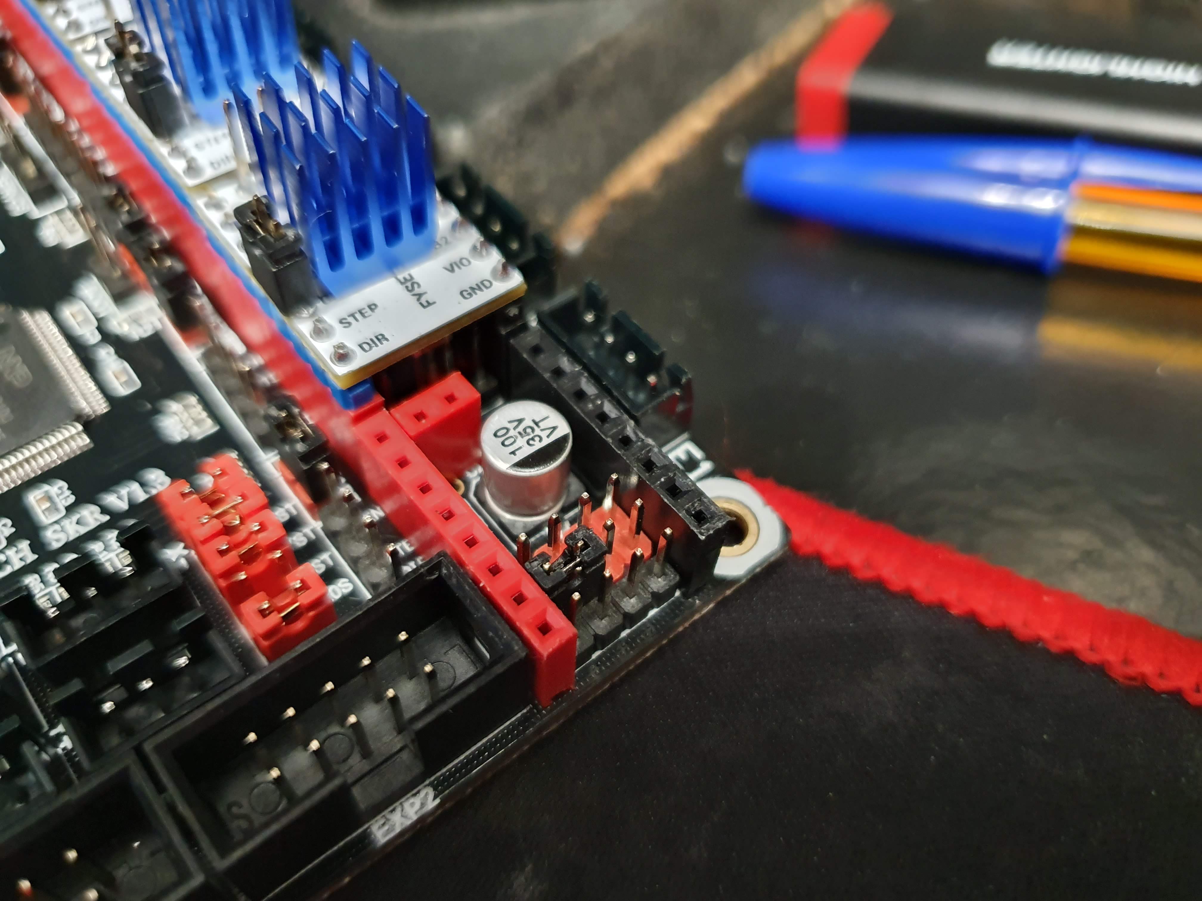
all working, had to connect 2 extra jumper:
TX to RX on the drivers (they have up facing pins):

and then bottom middle pin (under the driver in the block of 12 pin) to the next one up (which is for M3) pin. :
and now I have
Driver registers:
        X   0x80:08:00:00
        Y   0x80:0C:00:C0
        Z   0x80:0C:00:00
        Z2  0xC0:0C:00:00
        E   0x80:0C:00:00
Testing X connection... OK
Testing Y connection... OK
Testing Z connection... OK
Testing Z2 connection... OK
Testing E connection... OK
Thank you so much
pbathuk
on 19 Dec 2019
@pbathuk Glad it is working now.
atoomnetmarc
on 19 Dec 2019
@mLupine is the issue still the same with all the updates in the last 10 days?
 boelle
on 24 Dec 2019
boelle
on 24 Dec 2019
btw, who can confirm there is an issue? use the same configs as OP and the same hardware if possible
boelle
on 24 Dec 2019
@mLupine is the issue still the same with all the updates in the last 10 days?
Hey, sorry for the delayed response. The problem, actually, was outside the Marlin code. As @uorbe001 noted, my MS1/MS2 pins weren't removed and were connected to the printer's mainboard, effectively changing the "slave address" the stepsticks were available on. Removing the pins according to their correct combinations solved the problem, at last partially. Then there was the second issue, with the RX pins not being connected to an interrupt-capable mobo pin.
So, it turned out that the v3.0 are actually easier to use than the previous ones - aside from the fact, that the pins are labeled incorrectly on the silkscreen, there's no need to use resistors anymore. It's already present on the board and both the TX and RX pins are already available.
Guess I can close the issue then.
mLupine
on 24 Dec 2019
This worries me. As it's effectively shorting the SPREAD pin of the TMC2209 to the PDN. Will the SPREAD mode select not go crazy when UART is in use?
 pkucmus
on 28 Dec 2019
pkucmus
on 28 Dec 2019
This worries me. As it's effectively shorting the SPREAD pin of the TMC2209 to the PDN. Will the SPREAD mode select not go crazy when UART is in use?
The spread pin is not connected to anything - it neither goes into the printer board nor is it connected from above. Mode selection is done by UART via the two pins below the SP pin on the stepstick. I have it working for about two weeks now with no issues.
mLupine
on 28 Dec 2019
Thank you for the fast response. I just confirmed - it is connected to the SPREAD pin. To be more clear.

SPREAD on the TMC2209 on the FYSETC TMC2209 V3.0 stepstick is connected to the SP pin (wrongly marked as TX)

Then in the end on an SKR 1.3 board we end up shorting the SPREAD with the UART when we short the green and blue from the graphic I just made (just checked all that with a multimeter):
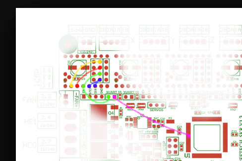
The easiest and probably safest solution (but ugly) is to run a jumper from the RX pin on the stepstick to the pink (from my "drawing").
pkucmus
on 28 Dec 2019
If anyone is interested in that solution here it is:

No jumpers on the mode select (beneath the step stick) and no soldering required (if you are okay with longer dupont wires). I cut mine and soldered them to the RX pin sticking out of the top of the step stick.
pkucmus
on 28 Dec 2019
If someone is in need for a deeper explanation, I shared my notes here: https://theres-probably-a-better-way-to-do-it.readthedocs.io/en/latest/pages/electronics/skr_1.3_and_fysetc2209v3.html
pkucmus
on 30 Dec 2019
@pkucmus thanks for the write up, I can confirm though that the above can be run through jumpers and UART works as expected, so technically there are 3 solutions.
I may try your one to see if it fixes the wire I have to run to use the sensorless homing, as currently I have to run a wire from the diag pin to the min end stop pin as the normal jumper route does not work.. not sure why, but might be due to my way of getting UART to work.
pbathuk
on 30 Dec 2019
Has anyone got these working on the SKR 1.4?
 jaysuk
on 4 Jan 2020
jaysuk
on 4 Jan 2020
I'm guessing it's the same or at least similar, one should be able to follow the steps I took in my "article" to figure it out.
pkucmus
on 4 Jan 2020
It doesn't have the Uart pins like the 1.3 does. The only available pins are under the driver. Slightly more awkward as they haven't released a schematic yet
jaysuk
on 4 Jan 2020

I'd say you need to put a jumper just on the "RST SLP" (very bottom left pins under the stepper) that would connect the PND of the Fysetc TMC2209 V3 to the CPU.
Marlin already expects specific pins so I guess they have it figured out: https://github.com/MarlinFirmware/Marlin/blob/2.0.x/Marlin/src/pins/lpc1768/pins_BTT_SKR_V1_4.h#L155-L171
You'd need to measure with a multimeter which of the pins under the X stepper are connected to the P1_10 pin on the CPU (I guess it's the "RST SLP" - the bottom left one) (https://os.mbed.com/users/synvox/notebook/lpc1768-pinout-with-labelled-mbed-pins/ - the diagram is rotated 90deg clockwise when compared to the SKR 1.3, I think its the same for 1.4)
pkucmus
on 4 Jan 2020
I found the documentation (as much as you can call pictures from Aliexress listing documentation), it's not going to be as easy as with the 1.3. I think your best bet is to short the bottom red pins and change the UART pins in Marlin. No idea to which though as to which pins "RST SLP" are connected is still a secret.
pkucmus
on 5 Jan 2020
I've been able to get it working for reference.
The second pin up on the left is connected to the CPU (so for X it is connected to P1.10).
I connected the bottom middle pin to that pin and then connected the TX and RX pins on top of the driver.

Thanks for your help.
jaysuk
on 5 Jan 2020
This worries me. As it's effectively shorting the SPREAD pin of the TMC2209 to the PDN. Will the SPREAD mode select not go crazy when UART is in use?
The spread pin is not connected to anything - it neither goes into the printer board nor is it connected from above. Mode selection is done by UART via the two pins below the SP pin on the stepstick. I have it working for about two weeks now with no issues.
Have an image on mega s? I like to see what you do with tmc2209 v3 from fysect. I have mines and i don’t know how to install.
 mdsavio
on 19 Jan 2020
mdsavio
on 19 Jan 2020
For FYSETC TMC 2209 V3.0 see this link
https://www.lesimprimantes3d.fr/forum/topic/25142-bigtreetech-skr-pro-v11-marlin-20-driver-2209-bltouch-pour-hypercube-evo-ii/page/9/#comments
 jaubertel769
on 19 Jan 2020
jaubertel769
on 19 Jan 2020
the mechanical solution to put the pins back in the right place is I think the best and will fit almost all cards
jaubertel769
on 19 Jan 2020
This solution works fine on my Bigtreeteck SKR Pro V1.1
jaubertel769
on 19 Jan 2020
the mechanical solution to put the pins back in the right place is I think the best and will fit almost all cards
I need with Trigorilla on Anycubic Mega S please.
mdsavio
on 20 Jan 2020
This solution works fine on my Bigtreeteck SKR Pro V1.1, the trigorilla mainboard is made with mega2560 CPU, TMC 2100 is ok but for 2209 V2.0 i dont know. For FYSETC TMC 2209 V3.0, not buy this version......not sure, but i think version FYSETC ver 3.0 is for motherboard FYSETC F6.
If you have already purchased them, the modification should work but I cannot guarantee it
jaubertel769
on 20 Jan 2020

jaubertel769
on 20 Jan 2020
If someone is in need for a deeper explanation, I shared my notes here: https://theres-probably-a-better-way-to-do-it.readthedocs.io/en/latest/pages/electronics/skr_1.3_and_fysetc2209v3.html
Thanks, great solution and analysis. Struggled with getting E1 up and running. Finally found out that pins for E1UART are swapped.
 maehtricks
on 22 Jan 2020
maehtricks
on 22 Jan 2020
the mechanical solution to put the pins back in the right place is I think the best and will fit almost all cards
I need with Trigorilla on Anycubic Mega S please.
did you solve it now?
 akula3
on 28 Feb 2020
akula3
on 28 Feb 2020
Do you think that this is only a FYSECT thing? would ERYONE's V3 also affected?
https://www.ebay.co.uk/itm/5pc-TMC2209-v3-0-Ultra-Quiet-Stepstick-Stepper-Motor-Driver-Module-Heatsink-UK/223911859339?hash=item34222fd48b:g:h0gAAOSwdzZeQ6Fv
 sibero80
on 3 Mar 2020
sibero80
on 3 Mar 2020
Do you think that this is only a FYSECT thing? would ERYONE's V3 also affected?
https://www.ebay.co.uk/itm/5pc-TMC2209-v3-0-Ultra-Quiet-Stepstick-Stepper-Motor-Driver-Module-Heatsink-UK/223911859339?hash=item34222fd48b:g:h0gAAOSwdzZeQ6Fv
Just installed on my SKR 1.3 and they are not afffected with this issue, they communicate ok. Only problem i have so far is get sensorless homing working
 Zefram88
on 22 Apr 2020
Zefram88
on 22 Apr 2020
when in doubt what to buy, you can always check that "article" of mine link under: https://github.com/MarlinFirmware/Marlin/issues/16220#issuecomment-569552374 - there's a table with different pinouts which will tell you if the thing you are about to you will work
pkucmus
on 22 Apr 2020
This thread has been automatically locked since there has not been any recent activity after it was closed. Please open a new issue for related bugs.
![lock[bot] picture](https://avatars1.githubusercontent.com/in/6672?v=4&s=40) lock[bot]
on 25 Jun 2020
lock[bot]
on 25 Jun 2020
This issue has been automatically locked since there has not been any recent activity after it was closed. Please open a new issue for related bugs.
![github-actions[bot] picture](https://avatars2.githubusercontent.com/in/15368?v=4&s=40) github-actions[bot]
on 24 Aug 2020
github-actions[bot]
on 24 Aug 2020
Related issues
 otisczech
·
3Comments
otisczech
·
3Comments
 Kaibob2
·
4Comments
Kaibob2
·
4Comments
 Anion-anion
·
3Comments
Anion-anion
·
3Comments
 ceturan
·
4Comments
ceturan
·
4Comments
 Tamonir
·
3Comments
Tamonir
·
3Comments