Marlin: [FR] Printrboard G2 SAM3X8C support
I have painstakingly extracted the pin configuration from g2Core for the Printrboard G2 and created a Marlin 2.0 pin file, I don't know what to do next. I understand its a DUE processor and is from the same family ATSAM3X but has less pins 100 vs 144.
I was able to get Klipper firmware running on, moved the axis around but the heaters would not turn on and I was controlling the DRV8825 current with software pwm sense hardware pwm support has not been implemented for the ATSAM3XC.
I tried compiling marlin 2.0 for DUE and got a ton of errors. I'm not sure what's needed next it's a little above my understanding but I assume there are some other files that need to be modified in the fastio_Due.h file
I would love some guidance on where to go from here, I have a lot of these g2 boards that are difficult to use with the g2Core firmware. Myself and many Printrbot Simple Pro owners would be forever thankful.
I added this line to boards.h
define BOARD_PRINTRBOARD_G2 1811 // G2 Printrboard SAM3XC Arduino DUE
Pinout and board files from g2core
https://github.com/synthetos/g2/blob/master/g2core/board/printrboardg2/printrboardG2v3-pinout.h
Page 15 has the pinout of this board /micro controller pin name
http://ww1.microchip.com/downloads/en/DeviceDoc/Atmel-11057-32-bit-Cortex-M3-Microcontroller-SAM3X-SAM3A_Datasheet.pdf
Klipper - https://github.com/KevinOConnor/klipper/issues/1121
Pin file and board file for G2
pins_PRINTRBOARDg2.zip
 drphil3d
All 143 comments
I can help test and work through this as I too have a PB Simple Pro which feels a bit stymied. Exactly the post I wanted to find.
 vmorrisPolar
on 30 Jan 2019
vmorrisPolar
on 30 Jan 2019
You're really starting from ground zero on this.
I suspect that there are three main problem areas:
- The PlatformIO environment isn't setup properly. I can help with that.
- The pins_PRINTRBOARDg2.h file needs work. If you want to keep your life simple I suggest leaving the fastio_Due.h file alone and making your pins_PRINTRBOARDg2.h conform to the Marlin pin numbering system.
- The correct digital motor current options are not selected in your configuration files
I have some down time this week while I wait for a replacement ramps_FD V1 board so I'll see if I can get something to compile.
I'm probably going to piss off the wife since the bathroom isn't done yet but .. I like playing with the low level stuff. If you send me the main board and the little expansion board I'll see what I can do. If that's of interest to you then send an email to bob.[email protected]. I'll be glad to send it back when we're done.
 Bob-the-Kuhn
on 30 Jan 2019
Bob-the-Kuhn
on 30 Jan 2019
Did you men "ATSAM3X8C" when you mentioned "ATSAM3XC"?
I'm pretty sure that none of the items missing in the "8C" chip are used by Marlin. If that's the case then the easiest way to get Marlin to compile for this board is to lie and say it uses the "8X" chip.
Using that method I got a sucessful compile by:
- Copying the guts of pins_PRINTRBOARDg2.h into pins_RAMPS_FD_V1.h
- Creating a minimal configuration.h to use the modified RAMPS_FD_V1 file
- Adding the pin SDSS. Marlin insists on having it set to something. I set it to a random number.
- Making the motor PWM array and pin defins match Marlin's requirements. Right now Marlin assumes that the DEFAULT_PWM_MOTOR_CURRENT array has three entries and that the X & Y steppers share a single PWM pin. That means we'll need to do some custom coding
- Corrected a Marlin bug in the XYZ defines in the motion modules.
Here are the modified files.
modified files.zip
If you can compile & download this into your board then start using M42 and the M43 utilities to verify the pin numbers in pins_PRINTRBOARDg2.h.
Bob-the-Kuhn
on 31 Jan 2019
Happily, I was wrong about needing custom coding. Marlin currently handles the PWM currents as written in pins_PRINTRBOARDg2.h.
Bob-the-Kuhn
on 31 Jan 2019
yeah its a sam3x8c, my mistake haha big difference there. wonderful I will try it out and also send out that board today
drphil3d
on 31 Jan 2019
I don't think it's a huge deal if X&Y share the same PWM value at least for most people.
drphil3d
on 31 Jan 2019
I'm able to compile and upload the firmware just fine. The stepper motors are going high by default when powered on but don't move. some pin assignments are mixed up x min should be y. but it's a start.
drphil3d
on 31 Jan 2019
SENT: M43
READ: PIN: 00        <unused/unknown>                       Output = 1
READ: PIN: 01        Y_MAX_PIN                              protected
READ: PIN: 02        <unused/unknown>                       Input  = 1
READ: PIN: 03        Z_MIN_PIN                              protected
READ: PIN: 04        X_MIN_PIN                              protected
READ: PIN: 05        <unused/unknown>                       Input  = 1
READ: PIN: 06        <unused/unknown>                       Input  = 1
READ: PIN: 07        <unused/unknown>                       Input  = 1
READ: PIN: 08        <unused/unknown>                       Input  = 1
READ: PIN: 09        <unused/unknown>                       Input  = 1
READ: PIN: 10        <unused/unknown>                       Input  = 1
READ: PIN: 11        <unused/unknown>                       Input  = 0
READ: PIN: 12        <unused/unknown>                       Input  = 0
READ: PIN: 13        <unused/unknown>                       Input  = 1
READ: PIN: 14        <unused/unknown>                       Input  = 0
READ: PIN: 15        HEATER_0_PIN                           protected
READ: PIN: 16        <unused/unknown>                       Input  = 1
READ: PIN: 17        <unused/unknown>                       Input  = 0
READ: PIN: 18        <unused/unknown>                       Input  = 0
READ: PIN: 19        <unused/unknown>                       Input  = 1
READ: PIN: 20        <unused/unknown>                       Output = 1
READ: PIN: 21        <unused/unknown>                       Output = 1
READ: PIN: 22        <unused/unknown>                       Input  = 1
READ: PIN: 23        <unused/unknown>                       Input  = 0
READ: PIN: 24        <unused/unknown>                       Input  = 0
READ: PIN: 25        <unused/unknown>                       Input  = 0
READ: PIN: 26        <unused/unknown>                       Input  = 0
READ: PIN: 27        <unused/unknown>                       Input  = 0
READ: PIN: 28        <unused/unknown>                       Input  = 0
READ: PIN: 29        <unused/unknown>                       Input  = 0
READ: PIN: 30        <unused/unknown>                       Input  = 0
READ: PIN: 31        <unused/unknown>                       Input  = 1
READ: PIN: 32        <unused/unknown>                       Input  = 0
READ: PIN: 33        <unused/unknown>                       Input  = 1
READ: PIN: 34        <unused/unknown>                       Input  = 1
READ: PIN: 35        <unused/unknown>                       Input  = 1
READ: PIN: 36        <unused/unknown>                       Input  = 1
READ: PIN: 37        <unused/unknown>                       Input  = 1
READ: PIN: 38        <unused/unknown>                       Input  = 1
READ: PIN: 39        <unused/unknown>                       Input  = 1
READ: PIN: 40        <unused/unknown>                       Input  = 1
READ: PIN: 41        <unused/unknown>                       Input  = 1
READ: PIN: 42        <unused/unknown>                       Input  = 0
READ: PIN: 43        <unused/unknown>                       Input  = 0
READ: PIN: 44        <unused/unknown>                       Input  = 1
READ: PIN: 45        <unused/unknown>                       Input  = 1
READ: PIN: 46        <unused/unknown>                       Input  = 1
READ: PIN: 47        <unused/unknown>                       Input  = 1
READ: PIN: 48        <unused/unknown>                       Input  = 1
READ: PIN: 49        Z_MS3_PIN                              protected
READ: PIN: 50        Z_MS1_PIN                              protected
READ: .              Z_MS2_PIN                              protected
READ: PIN: 51        <unused/unknown>                       Input  = 1
READ: PIN: 52        <unused/unknown>                       Input  = 0
READ: PIN: 53        <unused/unknown>                       Input  = 1
READ: PIN: 54 (A 0)  Z_STEP_PIN                             protected
READ: PIN: 55 (A 1)  Z_ENABLE_PIN                           protected
READ: PIN: 56 (A 2)  Z_DIR_PIN                              protected
READ: PIN: 57 (A 3)  <unused/unknown>   Analog in =   944   Input  = 1
READ: PIN: 58 (A 4)  <unused/unknown>   Analog in =   606   Input  = 1
READ: PIN: 59 (A 5)  <unused/unknown>   Analog in =  1023   Input  = 1
READ: PIN: 60 (A 6)  FAN1_PIN                               protected
READ: PIN: 61 (A 7)  <unused/unknown>   Analog in =   466   Input  = 0
READ: PIN: 62 (A 8)  <unused/unknown>   Analog in =   158   Input  = 0
READ: PIN: 63 (A 9)  MOTOR_CURRENT_PWM_E_PIN                Output = 0
READ: PIN: 64 (A10)  <unused/unknown>   Analog in =   526   Input  = 1
READ: PIN: 65 (A11)  <unused/unknown>   Analog in =     0   Input  = 0
READ: PIN: 66        <unused/unknown>                       Input  = 0
READ: PIN: 67        MOTOR_CURRENT_PWM_Z_PIN                Output = 0
READ: PIN: 68        MOTOR_CURRENT_PWM_XY_PIN               Output = 0
READ: PIN: 69        X_MS3_PIN                              protected
READ: PIN: 70        X_MS1_PIN                              protected
READ: .              X_MS2_PIN                              protected
READ: PIN: 71        <unused/unknown>                       Output = 0
READ: PIN: 72        <unused/unknown>                       Input  = 1
READ: PIN: 73        <unused/unknown>                       Input  = 0
READ: PIN: 74        MISO_PIN                               protected
READ: .              X_STEP_PIN                             protected
READ: PIN: 75        MOSI_PIN                               protected
READ: .              X_ENABLE_PIN                           protected
READ: PIN: 76        SCK_PIN                                protected
READ: .              X_DIR_PIN                              protected
READ: PIN: 77        FAN_PIN                                protected
READ: .              SDSS                                   protected
READ: .              SS_PIN                                 protected
READ: .              Y_MS3_PIN                              protected
READ: PIN: 78        Y_MS1_PIN                              protected
READ: .              Y_MS2_PIN                              protected
FANTASTIC!!!
The stepper motors are going high by default when powered on but don't move.
Sounds like:
- The steppers are powered up after a reset (can't turn them by hand)
- No movement when a commanded.
Are the steppers power up when a movement command is issued? If yes then try doubling the current. If not try flipping the X_ENABLE_ON flags.
Bob-the-Kuhn
on 31 Jan 2019
A friend of mine who knows a lot more about micro controllers then I told me that the registers many need to be set so the pin muxing is handled properly. I ran into an issue with Klipper where I was unable to get any of the fans or heaters to turn on, the developer suggested there may be a global pin that needs to be set to enable those pins.
These are the three files in order that reference each other that seem to have very important information in them.
Here is the pinout for this board
https://github.com/synthetos/g2/blob/master/g2core/board/printrboardg2/printrboardG2v3-pinout.h
https://github.com/synthetos/g2/blob/master/g2core/board/printrboardg2/motate_pin_assignments.h
https://github.com/synthetos/Motate/blob/master/MotateProject/motate/Atmel_sam3x/motate_chip_pin_functions.h
This is from PrintrboardG2v3. I think what it's saying is these pin assignments are not necessarily the same as what the actual pin is assigned on the micro-controller and that motate_pin_assignments.h is what has the physical pin number.
/*  See motate_pin_assignments.h for pin names to be used int he rest of the G2 code.
 *  EXAMPLES:
 *
 *  *** Vanilla pin example ***
 *
 *      _MAKE_MOTATE_PIN(4, A, 'A', 27);    // SPI0_SCKPinNumber
 *
 *      This assigns Motate pin 4 to Port A, pin 27 (A27)
 *      Look in motate_pin_assignments.h to see that this is kSPI_SCKPinNumber
 *
 *  ** Other pin functions ***
 *
 *      Please look in <Motate>/platform/atmel_sam/motate_chip_pin_functions.h
 */
/* NOTES:
    - Using kSocket1_InterruptPinNumber for INTERRUPT_OUT. Enabled in pin_assignments.h
    - kI2C1 reserved for filament sensor
 */
The first file was gold. It's almost as good as a schematic.
The last file indicates that some of the pins are inverted. I'll have to see which ones those are.
I don't see anything that implies a mux function.
I have a nagging suspicion that there is a filter and/or voltage divider between the DRV8825's Vref pin and the signal from the CPU. Any idea what the motor PWM frequency and duty cycle range are?
I'll look at it and generate configuration files that match tomorrow morning.
Bob-the-Kuhn
on 1 Feb 2019
I pulled this info out of https://github.com/synthetos/g2/blob/master/g2core/board/printrboardg2/hardware.h
/**** Stepper DDA and dwell timer settings ****/

//#define FREQUENCY_DDA     200000UL        // Hz step frequency. Interrupts actually fire at 2x (400 KHz)
#define FREQUENCY_DDA       150000UL        // Hz step frequency. Interrupts actually fire at 2x (300 KHz)
#define FREQUENCY_DWELL     1000UL
#define FREQUENCY_SGI       200000UL        // 200,000 Hz means software interrupts will fire 5 uSec after being called
here is the updated pin file updated pin.zip
oh take a look at this https://github.com/synthetos/Motate/blob/master/MotateProject/motate/board/ArduinoDue/motate_pin_assignments.h
This refers to pins that are not available on other platforms but cannot be masked out
https://github.com/synthetos/Motate/blob/master/MotateProject/motate/Atmel_sam_common/SamPins.h
drphil3d
on 1 Feb 2019
I've made a little progress.
I think the attached will spin the X stepper if it's attached to MOTOR_1. I doubt that the other steppers will spin.
G2_Marlin.zip
I'm pretty sure that custom coding is going to be needed. If the file printrboardG2v3-pinout.h is accurate …
- Some of the port/pin combos used by this board are not defined for the Due.
- The stepper Vref PWM pins are not supported on the DUE. It looks like G2 uses timers to implement software PWMs. Marlin would need to add this capability.
Please do a little testing on this image:
- See how functional the X stepper is. Does it rotate in both directions? Do the microstep pins work correctly?
- I've used the port assignments in printrboardG2v3-pinout.h to re-number the pins_RAMPS_FD_V1.h file. See if things like end stops, heaters and temperature inputs work properly.
I'm a long ways away from looking at what it'll take to support the display.
Can you point me to a diagram of how these various boards connect to each other and to the printer?
Bob-the-Kuhn
on 3 Feb 2019
Motor 1 = z
Motor 2 = x
Motor 3 = y
Motor 4 = e
The ribbon cable has motors y and e
We can also look at Klipper and see what was done to get things moving.
drphil3d
on 3 Feb 2019
Here is more info about how the whole system is designed to work. I also have the gerber files for the g2. http://www.appfruits.com/2016/11/printrbot-simple-2016-hardware-pcb-explained/
Interesting comment about the sam3xc hardware source code
https://github.com/KevinOConnor/klipper/pull/1055#issue-241506764
drphil3d
on 3 Feb 2019
Sounds like this board was fully functional using Klipper. Please post your Klipper configuration file. That should contain a lot of the pin info I'm looking for.
Bob-the-Kuhn
on 4 Feb 2019
I was able to read the endstop status and move the motors just fine but was unable to control heaters. https://github.com/KevinOConnor/klipper/issues/1121#issuecomment-457800253
drphil3d
on 4 Feb 2019
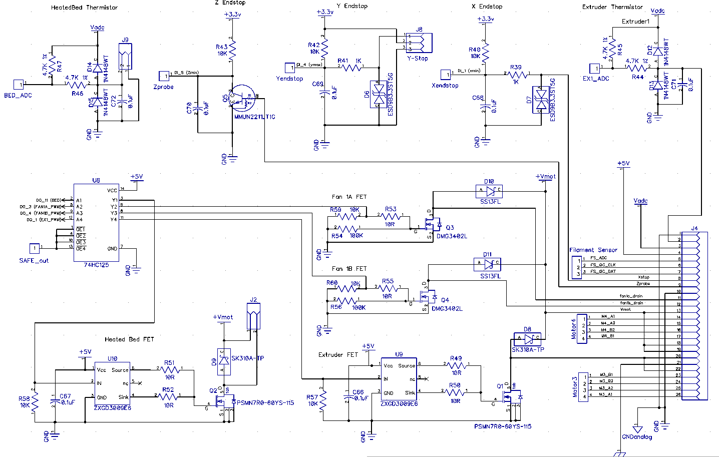
I've been able to beep out enough of the circuitry to show that PA7 provides an AC coupled enable signal to the FETs.
Now I need to find the frequency & duty cycle areas that make the system happy.
Bob-the-Kuhn
on 5 Feb 2019
2uS low pulse every 50mS makes it happy.
I can control the FAN FETs with no problems.
It'll take a new board definition in PlatformIO to control the extruder and bed FETs. The port/pin combos used by the hardware are not assigned logical pin numbers in the Due system.
Bob-the-Kuhn
on 5 Feb 2019
Are you serious! That's awesome, I struggled with it for so long.
ps: Just finished that part I'll send it to you tomorrow.
drphil3d
on 5 Feb 2019
When I power on the Y and Z axis are energized and buzzing, G28 makes the tone change. I jogged the Z axis and I could hear it trying to move.
drphil3d
on 6 Feb 2019
Just got in some Nema 17 steppers so I should be able to do some real testing on the motors.
I have not yet figured out how to access the bed and extruder FETs with a method that would make it into the Marlin code base.
I'm currently playing with a new board definition for PlatformIO. Unfortunately the Arduino software requires access to ports that are not present on the SAM3X8C. I may have to tell PlatformIO this is an 3X8E but with a custom pin map.
Another option is to play with the macro defines for the heaters and bed. Maybe create a WRITE macro that uses port & pin instead of logical pin.
I've got some updates on the pin numbering for the mortors. It appears the G2 pin defs for Motor 2 are wrong but maybe it was my fat probe touching more than one pin that drove me to this conclusion. So far the G2 defs have been perfect ecept for the motor current pin mapping and possibly Motor 2.
Bob-the-Kuhn
on 6 Feb 2019
interesting, If I'm reading this correctly It would seem to me that they are using a linkage file to modify the pin mapping for sam3xc for this specific board sense they originally wrote the code for the sam3xe. https://github.com/synthetos/g2/blob/1ff7f600923c622fbf2b546e7d15a24498d1d1c1/g2core/board/printrboardg2/motate_pin_assignments.h#L249
Here is some info that may help out
https://github.com/synthetos/g2/issues/371#issuecomment-408636839
drphil3d
on 6 Feb 2019
Here we go this explains things.
https://github.com/synthetos/g2/issues/371#issuecomment-408630672
https://github.com/synthetos/g2/blob/edge/g2core/temperature.cpp#L256
// Output 1 FET info
// DO_1: Extruder1_PWM
const int16_t fet_pin1_freq = 100;
if TEMPERATURE_OUTPUT_ON == 1
PWMOutputPin
else
PWMOutputPin<-1> fet_pin1;// {kPWMPinInverted};
3766
drphil3d
on 6 Feb 2019
I've gotten brave enough (desperate enough) to solder some wires to the board. I can now look at all the Motor 1 signals using a logic analyzer. Much easier to see what is going on.
I think the buzzing is coming from the 500Hz square wave my test code is feeding to the Vref pins. What the chips are seeing is a 75% duty cycle wave. Apparently the DRV8825 is fast enough to respond to the off time of the Vref signal. I think I'll play with that next.
I think I have the configuration_adv.h file setup to implement the microstep selection feature. I need to do more testing before declaring victory.
There are 8 pins used by the G2 that are not in the Arduino/DUE pin map. I've modified fastio to use the G2 defs when that motherboard is selected. The results in fastio WRITE and READ functions accessing different port/pin combos than the Arduino/DUE digitalRead and digitalWrite functions. Functionally that's not a problem but it makes trouble shooting & verification a real bear because the M42 & M43 commands can't access/view/write the 8 pins.
Bob-the-Kuhn
on 7 Feb 2019
I may not have mapped the microstep pins out correctly which would
attribure to the buzzing sound instead of movement.
>
drphil3d
on 8 Feb 2019
The buzzing is due to the 1KHz square wave I was feeding it. I've got an UGLY 10KHz current PWM working & the buzzing is gone.
Here's a snapshot of the code:
- Motor 1 is the only one that works 100%
- Motor 2 moves but doesn't disable when it should.
- Motors 3 & 4 do nothing.
- The stepper currents can be changed via configuration_adv.h settings.
- Microsteps may be working. I don't remember how far I got in testing them.
- Haven't looked at the FETs in a few days. They should still be working.
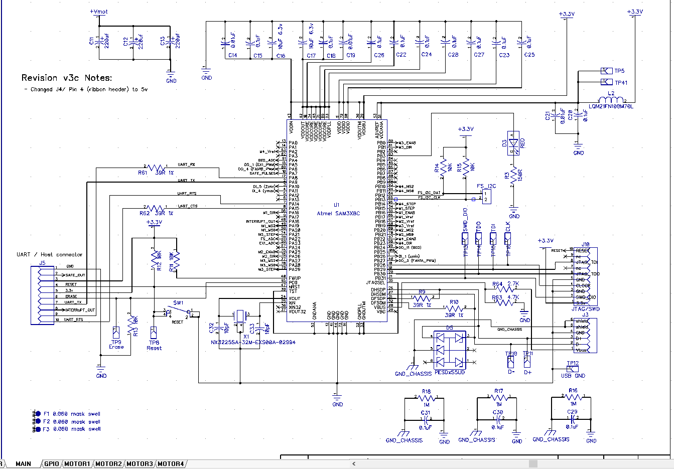
The schematic agrees with the pins file you provided.
I'm going to have to solder wires to the Motor 2, 3 & 4 drivers before I can make more progress.
I need to put this on the back burner for a bit. The wife is having surgery Wednesday which means well intentioned people are coming which means I need to clean up all my messes. I'll probably be spending half days on that for a bit.
Bob-the-Kuhn
on 8 Feb 2019
I will do some testing and see what I can do. I have a feeling the micro stepper pins may be reversed on motor 3, 4.
Where you able to get the hotend fet to turn on?
I greatly appreciate the work you have done. If this ends up working out I can give you a few more boards for other projects.
drphil3d
on 8 Feb 2019
Yes, I was able to get all four FETs to turn on.
I just tried motor 2 and it seems happy. The disable worked as it should. Maybe I typed the command in wrong earlier.
Bob-the-Kuhn
on 8 Feb 2019
Oh excellent!! That’s exciting
drphil3d
on 8 Feb 2019
I've got it working. Ugly code by all the FETs and motors work.
Here's a snapshot of the code. Marlin_G2_2019-02-09.zip
I'm going to make the code presentable and then start on the display. Please post a snapshot of what it looks like with the G2 code.
FYI - here's what the board looks like now.
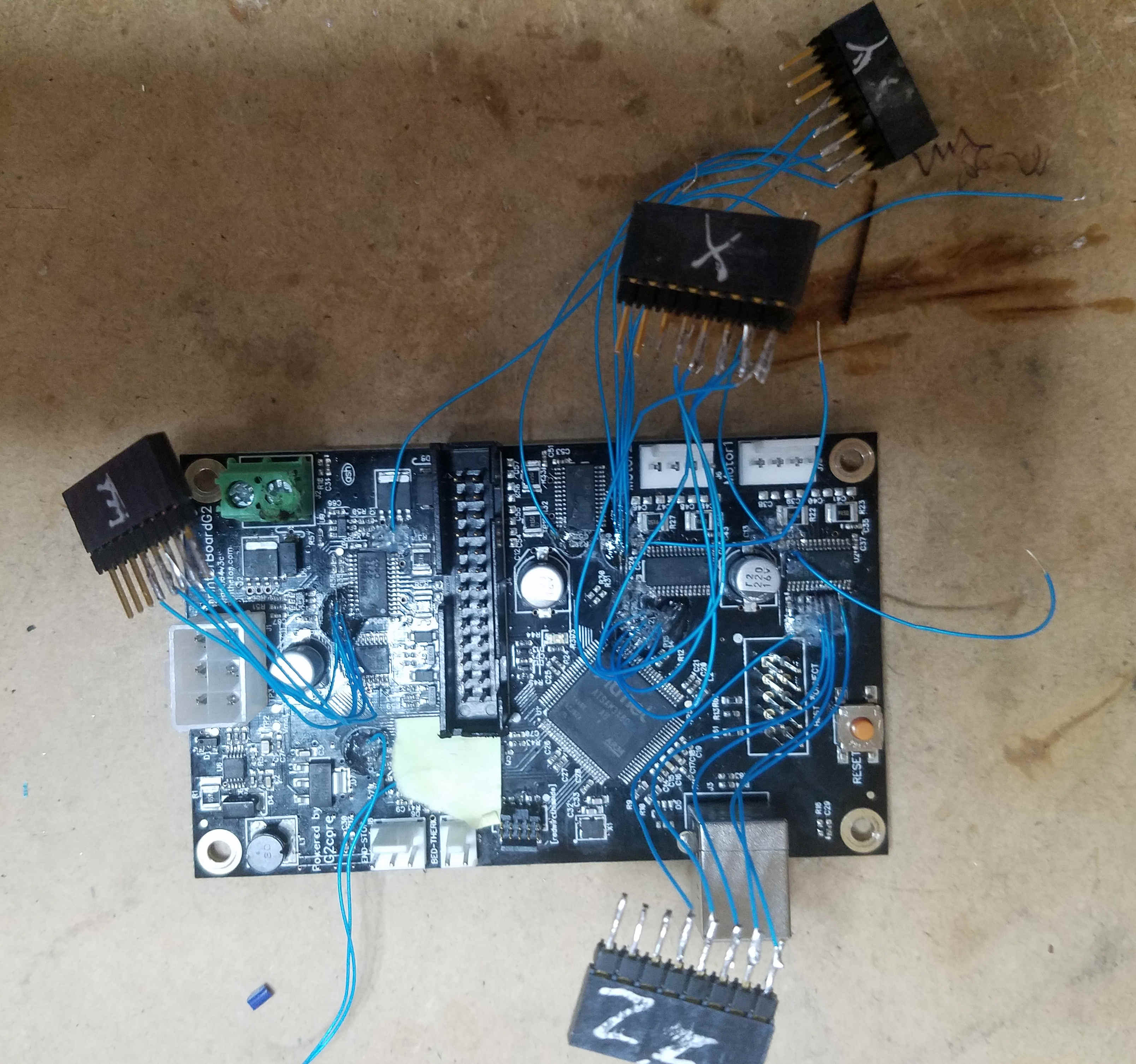
Bob-the-Kuhn
on 9 Feb 2019
WOW! I don't even have words thats pretty impressive. I'm going to try it out right now.
drphil3d
on 10 Feb 2019
It works! The hotend seems to be partially powered because I smelled burning plastic and the thermistor was reading 70c only a 30 seconds after connecting to it via usb.
the X and Z axis are swapped.
https://www.youtube.com/watch?v=UOBBtOsjVYE&feature=youtu.be
drphil3d
on 10 Feb 2019
Here's the corrected pins file.
Bob-the-Kuhn
on 10 Feb 2019
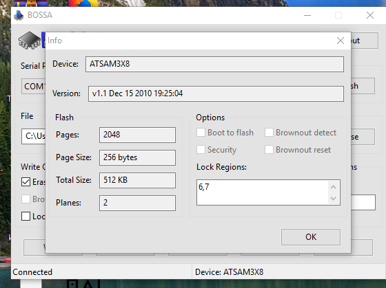
I somehow locked my processor
AVAILABLE: atmel-ice, blackmagic, jlink, sam-ba, stlink
CURRENT: upload_protocol = sam-ba
Looking for upload port...
Auto-detected: COM10
Forcing reset using 1200bps open/close on port COM10
Waiting for the new upload port...
Uploading .pioenvs\DUE_USB\firmware.bin
Atmel SMART device 0x284e0a60 found
Flash page is locked
Erase flash
* [upload] Error 1
[ERROR] Took 19.79 seconds
drphil3d
on 10 Feb 2019
I swapped out the boad, programmed it, then went to program it again and get the same result. yikes
drphil3d
on 10 Feb 2019
Solved the issue I was having with the security bit by using https://www.microchip.com/developmenttools/ProductDetails/atmel%20sam-ba%20in-system%20programmer#additional-summary
I had firmware on the board and was messing around with it, but after I
went to program it again I seem to have put it in some state where it won’t
exit programming mode but won’t accept new firmware.
I did enable EEPROM option in marlin maybe it’s not happy about that?
I had some really strange behavior, moving the Y axis away from the end
stop switch, as soon as the switch was in the open position the neo pixels
turn green. It’s repeatable beheavior.
I must not have the microstepping working correctly, the z axis moves way
to far way too fast regardless the steps per mm being set correctly. (400
at 16x microstepping.)
Also the x and y axis end stops switch assignments are swapped. I’m able to
home the Z axis.
I can control the Fan just fine.
We are so close! I have more board files for you as well.
Philip Mally
3D Printing & Rapid Prototyping Services
530-205-3210
[email protected]
drphil3d
on 10 Feb 2019
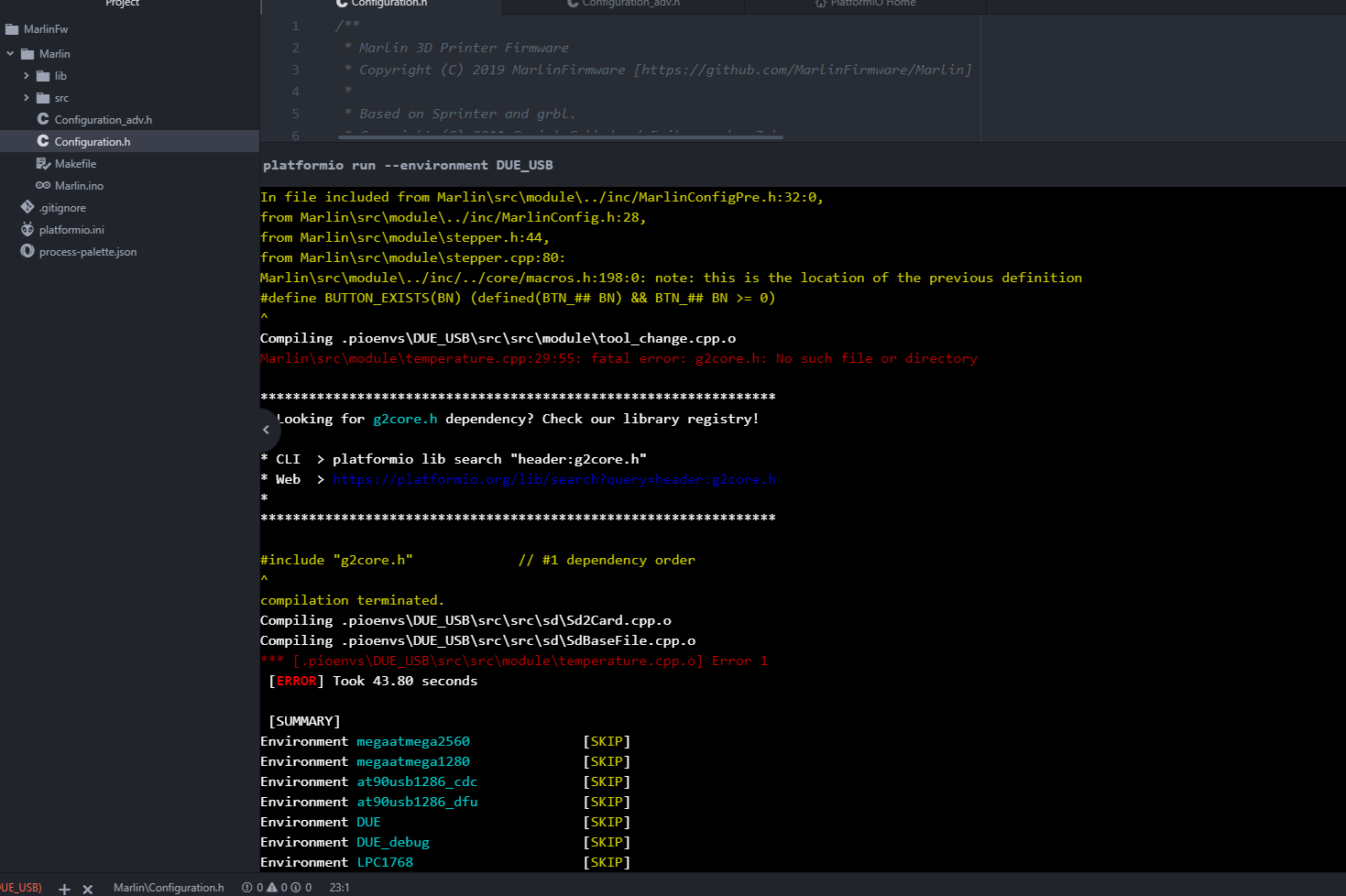
I tried to compile using the new pin file and it fails:
had to add this line back in
#define MOTOR_CURRENT_PWM_RANGE 2750 // (3.3 Volts * 100000 Ohms) / (100000 Ohms + 20000 Ohms) = 2.75 Volts (max vref)
Marlin\src\module\stepper.cpp: In static member function 'static void Stepper::digipot_current(uint8_t, int16_t)':
Marlin\src\module\stepper.cpp:2492:98: error: 'MOTOR_CURRENT_PWM_RANGE' was not declared in this scope
define _WRITE_CURRENT_PWM(P) analogWrite(MOTOR_CURRENT_PWM_## P ##_PIN, 255L * current / (MOTOR_CURRENT_PWM_RANGE))
^
Marlin\src\module\stepper.cpp:2496:13: note: in expansion of macro '_WRITE_CURRENT_PWM'
_WRITE_CURRENT_PWM(X);
drphil3d
on 10 Feb 2019
Here are the schematics and source for the LCD
Printrhub-master.zip
Power Board V1.2 Docs.zip
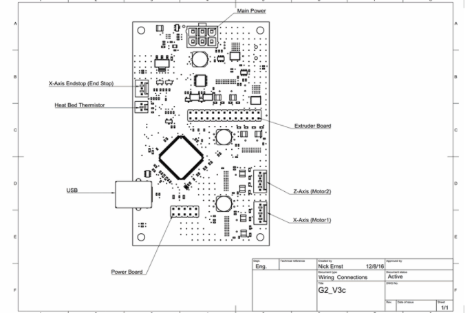
Printrboard G2 V3c.zip
drphil3d
on 10 Feb 2019
Good News, I can home Y and Z but for some reason can't move my X axis just makes buzzing noise.
I have my hotend unplugged as it seems to be enabled by default and thats a bit dangerous lol.
After cracking open an unmodified simple pro I found Z is plugged into Motor 2
drphil3d
on 10 Feb 2019
I had to change microstepping to 16x and the pins to this for the x axis to move
nevermind I wasn't editing the correct file just ignore this.. I need to go to bed
define X_STEP_PIN 75 //
define X_DIR_PIN 74 //
define X_ENABLE_PIN 73 //
I can hear a beep noise about every 3 seconds I can also hear it louder when the motors are moving. I also can make strange noises when playing with the fan speed.
I'm able to home XYZ! Progress!
drphil3d
on 10 Feb 2019
Seems like I've spend most of the evening shooting myself in the foot.
Here's another snapshot. I think the one I posted earlier may not have been setting the custom pins as outputs.
I've been doing most of my downloads via the USB port. Sometimes I use the JTAG port.
I have not seen the "Flash page is locked" error before. I'm surprised the erase pin didn't fix the problem. Worst case you send me the tanked boards & I'll download them via the JTAG port.
Bob-the-Kuhn
on 10 Feb 2019
I've opened PR #13116 to get feedback.
Bob-the-Kuhn
on 10 Feb 2019
I finally understand how the power module, LCD & G2 board hook up.
Looks like my little 12V supply doesn't have enough muscle to power the 5V supply on the power module. Looks like I'll need to look for something beefier.
The LCD looks rather intimidating at first glance. Can you point me to the 3X8C code that interfaces with it? Hopefully it'll supply most of the needed code.
I'm wondering who controls who in the system. If all the menus reside on the LCD and it just queiries the SAM3X8C for data then we probably won't be able to interface it to Marlin in a meaningful way.
Bob-the-Kuhn
on 10 Feb 2019
https://github.com/Printrbot/Printrhub/blob/master/README.md
The informative link here is Phillip’s blog... he was the mastermind behind the firmware on the printrhub... http://www.appfruits.com/2016/11/printrbot-simple-2016-commstack-explained/
 abdrumm
on 10 Feb 2019
abdrumm
on 10 Feb 2019
I don't think I'm interested in the ESP/MK20 COMMSTACK communications.
What I want to know is the how and what of the MK20/G2 communications. Example: When the user brings up a screen that has temperature on it, how does the MK20 ask for the data and how should the G2 respond?
Bob-the-Kuhn
on 10 Feb 2019
It's communicating over UART, there are gcode commands in the esp firmware for things like loading and unloading filament, setting temperature, etc.
Esp3d is very similar in function
https://github.com/luc-github/ESP3D
drphil3d
on 10 Feb 2019
The g2 emulates marlin, so assume the communication from the hub is talking marlin... while early on, we spoke the g2core language (Json)... but I thought we dumped that. Since my programmer left, I can’t soeak w authority, only point to the firmware for the hub on github: https://github.com/Printrbot/Printrhub/blob/master/README.md
abdrumm
on 11 Feb 2019
What does it take to power up the display?
I've plugged the 14 pin cable into the hub and the power module.
The 10 pin cable is plugged into the hub and the G2 board.
There's 12V on the power module past the fuse.
Bob-the-Kuhn
on 11 Feb 2019
The display should power on w the powerboard power switch... you might try reversing the cable going to the hub... if reversed, it remains black. It should signal the power board to give power - via the relays- to the g2
Brook
Sent from my iPhone
On Feb 10, 2019, at 6:09 PM, Bob Kuhn notifications@github.com wrote:
What does it take to power up the display?
I've plugged the 14 pin cable into the hub and the power module.
The 10 pin cable is plugged into the hub and the G2 board.
There's 12V on the power module past the fuse.—
You are receiving this because you commented.
Reply to this email directly, view it on GitHub, or mute the thread.
abdrumm
on 11 Feb 2019
The display should power on w the powerboard power switch... you might try reversing the cable going to the hub... if reversed, it remains black. It should signal the power board to give power - via the relays- to the g2
abdrumm
on 11 Feb 2019
I take it that the 1/4" spade terminals is where a switch goes?
Bob-the-Kuhn
on 11 Feb 2019
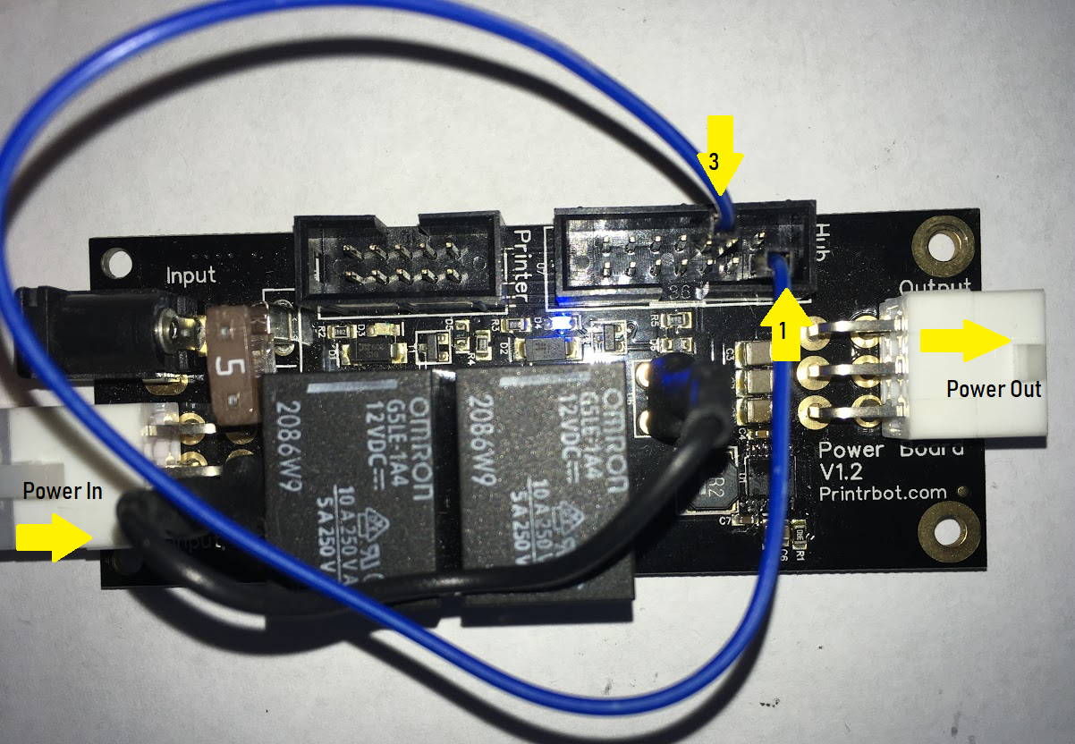
You can also jump two pins on the powerboard - the ribbon cable plug that normally goes out to the hub- to give power to the g2 when hub is not connected. Looking down on the powerboard with front of bot closest to you...Jump the bottom lower pin in the left row and the third pin up from bottom in the right row
abdrumm
on 11 Feb 2019
I HAVE POWER !!!!
All it took was finding a connector that had a fat center pin to match my wall warts and realizing that pin one on the connector housing wasn't actually the pin one of the board. Someone needs to take a basic technician course.
Bob-the-Kuhn
on 11 Feb 2019
This is how to power on the relays without the hub connected.
The hub sends mostly marlin gcode commands some may be in json
drphil3d
on 11 Feb 2019
Woohoo! Power!
abdrumm
on 11 Feb 2019
How do you get it to send something to the G2? I've tried tying CTS high & low but nothing happened.
Bob-the-Kuhn
on 11 Feb 2019
Where is the MK20 software?
Where is the G2 serial init routine?
Bob-the-Kuhn
on 11 Feb 2019
It’s all in the printrhub repo. I’ll see if I can dig some of it up
Philip Mally
3D Printing & Rapid Prototyping Services
530-205-3210
[email protected]
drphil3d
on 11 Feb 2019
I can see RS232 data being transmitted by G2 and on the FTDI port.
Bob-the-Kuhn
on 11 Feb 2019
Hello guys.. I have been digging the printrhub.. Maybe I can help. Where you should look is:
https://github.com/Printrbot/Printrhub/blob/master/mk20/src/Printr.cpp
I believe that the g codes are sent direct through the serial.
I'm looking now what is the SendLine to make sure.
 dmsmartinsUS
on 12 Feb 2019
dmsmartinsUS
on 12 Feb 2019
So I found the pin's used at the printrhub:
https://github.com/Printrbot/Printrhub/blob/master/mk20/src/framework/core/HAL.h
Has the serial and other pins..
dmsmartinsUS
on 12 Feb 2019
Found the MK20 printer serial code. Definitely using a Gcode dialect different than Marlin's.
I can see RS232 data being sent by the LCD.
Bob-the-Kuhn
on 12 Feb 2019
dmsmartinsUS
on 12 Feb 2019
dmsmartinsUS
on 12 Feb 2019
Thanks - those should be a big help.
So far all I see is a couple of 8 byte messages after power up. Both are "Y", then "(" and then six non-ASCII bytes.
The LCD comes up apparently in the projects menu with "GCODE UPLOAD TEST" displayed. Pressing the OPEN icon gets me to the JOBS menu. When I press the "print" icon the "PRINTING" menu comes up. Nothing comes out the serial port. It does say "Print Support: No" on the screen.
I did find one project that went into the download menu. After 10 minutes of no activity I backed out.
Is there a password that I need to enter so that I can change the WIFI settings and get this on the air?
Its looking like the M20 is expecting only JSON responses.
More digging tomorrow.
Bob-the-Kuhn
on 12 Feb 2019
It should have a network labeled Printrbot that you can connect to, I believe the firmware / ui / config for the mk20 / display is stored on the SD card along with the gcode files from the cloud.
I also probably should have mentioned earlier that the printrhub was a cloud based controller, it was not designed for local printing, however it can with some software modifications. The printrbot cloud server was taken offline about 4 months ago. It worked by sending the cloud an stl file to slice and it would then be downloaded to the printer where you could go and start the print. It was a bit ahead of its time and was missing the ability to just send a gcode file locally. Unfortunately due to that major shortcoming It was not well received by the 3d printing community. The cloud also had a 3mb upload limit. :(
However there is a way to push sliced gcode files to the printrhub using PrintrBotSelfHost I just discovered it this evening and forked into the Printrbot Repo.
https://github.com/Printrbot/PrintrBotSelfHost
This may also help if anyone wants to modify the source.
https://github.com/Printrbot/Printrhub/wiki/Flashing-ESP
drphil3d
on 12 Feb 2019
I knew it was cloud based but didn't understand what that really meant.
The current Printhub, is it of any value in a Marlin system? I've been assuming that things like status and simple motion commands were available via the Printhub. Is there value to the user?
Bob-the-Kuhn
on 12 Feb 2019
It was quite useful for leveling the bed, choosing files from thumbnail images, setting up WiFi SSID and password. Also choosing filament. I think marlin needs better UI than a 20x4 character lcd screen w an old knob.... today that looks and feels ancient. But a web server and a phone screen may do the trick.
The argument against using onlya phone screen is that you need a cancel button or something for convenience and safety.
abdrumm
on 12 Feb 2019
My dream is to be able to do the following without a USB cable:
- Have the local info/control now available through the RepRap Full Graphics LCD controller.
- Local storage of gcode files so can do long prints without worrying about the user's computer or network dying.
- Have a Repetier Host style control panel available on the user's computer.
- Download new Marlin images and Gcode files from the host.
What is the current system capable of doing (without re-writing the Printhub firmware)?
Bob-the-Kuhn
on 12 Feb 2019
The existing printrhub has a swipe screen of project thumbnails with “download” button, clicking reveals a swipe list of model thumbnails, each having a print button.
Settings menu: WiFi settings, password screen to lock down printer, z height adjustment, filament selection (it stores a database of temps programmable from the web app... don’t have to resource to change material type) and a led control menu
That’s it
Esp3d on github has the pronterface controls you want... it all fits on esp. it provides ui through a small web server
abdrumm
on 13 Feb 2019
What your describing is basically what Klipper does but with the requirement of a raspberry pi which handles firmware, path planning, storage filesystem, networking and just uses the MCU for moving motors and controlling the fets. The reprap full graphic display is supported and controls the printer. The display is completely customizable including custom menus that you use to select your gcode files which can be on a usb thumb drive or a directory. Klipper stores its firmware on the pi which is just a simple text file so updating it is very easy. Klipper can be accessed through pronterface, repetier host or octoprint at the same time as a reprap lcd. It's very versatile.
I actually got Klipper very close to working on the sam3xc, here is the config file if you want to mess with it. XYZ homes, endstops work, thermistors work just couldn't get the fets to turn on.
g2printrboard mostly complete config.cfg.txt
To turn on the stepper motors these commands have to be entered into the terminal at runtime.
SET_PIN PIN=motor_x_pwm VALUE=0.5
SET_PIN PIN=motor_y_pwm VALUE=0.5
SET_PIN PIN=motor_z_pwm VALUE=0.5
SET_PIN PIN=motor_e_pwm VALUE=0.5
drphil3d
on 13 Feb 2019
Look what I found. Motor 1 is X - Motor 2 is Z
I created a repo for the printrboard G2 https://github.com/Printrbot/printrboardg2
drphil3d
on 13 Feb 2019
I'm sorry to report I've ruined the Printhub by spilling my Dr. Pepper on it. Washing it & drying didn't keep the MK20 from getting way too hot.
Philip - can you send me another?
Also, I'd like to have an ELF for the standard G2 image. I want to install it on the unit I have and then watch the serial data between the two.
Lastly, should the spring/hinge clamp you printed for me be here by now?
Bob-the-Kuhn
on 14 Feb 2019
Yeah it should have been there by now. I didn't get tracking on it so I don't know what happened. I can just print another and ship it out with the hub. No worries :)
Here is the documentation and firmware for the G2
https://github.com/abdrumm/printrbot-docs/
drphil3d
on 14 Feb 2019
While you're at it, your could also send the G2 cards you can't download anymore. I'll put the JTAG header on download that way.
Bob-the-Kuhn
on 14 Feb 2019
I’m still trying to get some idea of what new functionality would be needed on the Marlin/G2 side if we were to make the G2 <-> Printhub serial port active.
What do you guys envision as the role of the Printhub when the G2 board is running Marlin?
In my very limited understanding of the Printhub I think the user can do the following (without accessing the non-existent cloud):
- Send/print Gcode files already on the SD card.
- Invoke utilties like the filament change utility.
In order to have that functionality, we’d need to implement some type of interpreter for the JSON commands and non Marlin Gcode that would be coming from the Printhub.
Can the G2 board initiate SD card access? If that’s true then host software, via the USB port, could save Gcode files to the Printhub’s SD card, Marlin could emulate EEPROM and Marlin could make the SD card available via the composite USB device.
I have a good idea of where/how to intercept the data being sent by the Printhub What I don't have is a handle on is how to generate responses the incoming data.
Bob-the-Kuhn
on 14 Feb 2019
Bob,
The ideal is change the esp8266 to have a version of ESP3D. That way you would have a web interface to upload the gcode to printrhub sd card. and also control from the esp8266. the teensy would do the printer communication and manage the display and sd card.. Look this diagram. Basically removing the cloud part..
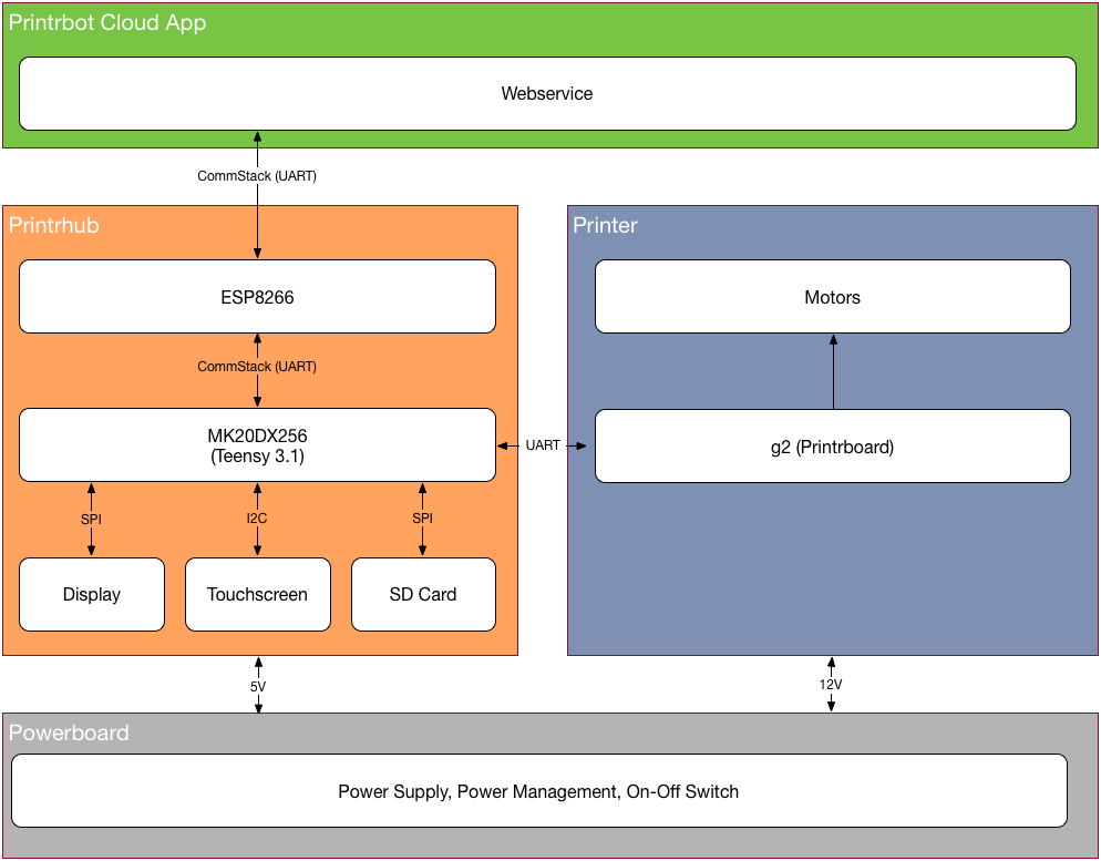
dmsmartinsUS
on 14 Feb 2019
What does it take for a user to update the Printhub with the new ESP8266 firmware?
Bob-the-Kuhn
on 14 Feb 2019
That is the unknown, as of now. It might be possible to use the OTA esp firmware updated... but I don’t really know. I do have the instructions on how we used to update the firmware on the g2 via usb cable I sourced via amazon.
abdrumm
on 15 Feb 2019
I've been downloading new images to the G2 board via the USB port. Marlin and PlatformIO make a nice combination.
I see an FTDI connector on the Printhub. I expect that's how it gets a new image.
Bob-the-Kuhn
on 15 Feb 2019
Yes, the FTDI connector is used to program the ESP8266.
It also appears that the ESP8266 can download the MK20 via the MK20's JTAG port.
Bob-the-Kuhn
on 15 Feb 2019
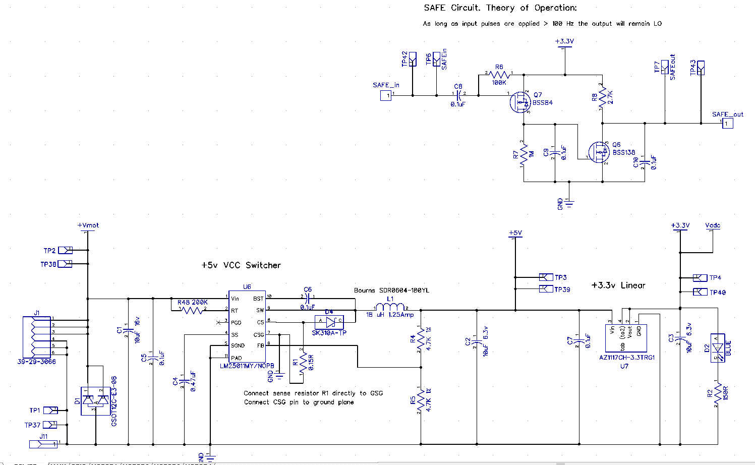
I installed diptrace and what do you know the Schematics are right there in the printrboard g2 v3.dch file I posted earlier.
SAFE Circuit. Theory of Operation:
As long as input pulses are applied > 100 Hz the output will remain LO
drphil3d
on 18 Feb 2019
I sent a bunch more files with secret g2 info... checking out
It’s a Dropbox link via text
Brook
Sent from my iPhone
On Feb 17, 2019, at 4:15 PM, Philip Mally notifications@github.com wrote:
I installed diptrace and what do you know the Schematics are right there in the printrboard g2 v3.dch file I posted earlier.
SAFE Circuit. Theory of Operation:
As long as input pulses are applied > 100 Hz the output will remain LO—
You are receiving this because you commented.
Reply to this email directly, view it on GitHub, or mute the thread.
abdrumm
on 18 Feb 2019
YEAH!!
I was able to use the trial version of DIPTRACE to get good quality PDFs of the schematics of G2, power board and Printhub..
Bob-the-Kuhn
on 18 Feb 2019
The Dropbox link - does it have more than is on GitHub? If yes then please send me the link.
Bob-the-Kuhn
on 18 Feb 2019
https://www.dropbox.com/s/el9lv7gl6ytn3g8/G2%20and%20stuff.zip?dl=0
It’s a variety.
Brook
abdrumm
on 18 Feb 2019
@drphil3d problem solved?
 boelle
on 21 Feb 2019
boelle
on 21 Feb 2019
As of right now I've been working on Klipper, I've been able to get everything working except for reading the thermistor values properly because the thermistor is running at 3.3v not 5 volts like most boards.
https://github.com/KevinOConnor/klipper/issues/1121
drphil3d
on 22 Feb 2019
maybe click green close button below?
boelle
on 22 Feb 2019
you mean the white close button? we're still working on this
drphil3d
on 22 Feb 2019
yep, the white one :-D you can still write to issue after closed
boelle
on 22 Feb 2019
Let's leave this one open. It definitely fits in Bo's definition of what should be an issue.
Bob-the-Kuhn
on 22 Feb 2019
agree.... i have read about 1000 issues over the last 2 days and i made a few screwups along the way
and to little sleep did not help it either
boelle
on 22 Feb 2019
Hey Bob what was the status of your latest marlin snapshot? The first one you had posted sets the safe signal on and the mosfets on at runtime which is obviously bad, but it was close to working without issue.
drphil3d
on 22 Feb 2019
Got two LCDs, two G2s and 4 breakout boards plus some cables I don't know what to do with.
I'm going to (hopefully) finish up my work on the L6470/powerSTEP01 driver work. I have motors spinning with both. I expect it'll be 2-3 days before I get back to the G2 work.
The latest is on the PR. If I remember correctly the last snapshot was a copy of the code on the PR.
I don't agree that it's bad to have the safe signal always on. In my view it's purpose is to shut down the FETs if the CPU hangs.
Did you get a chance to test the thermistor table? If it works then I'll add it to the PR.
I'm still not clear on what role, if any, that the current LCD/Printhub can play when Marlin is loaded.
Bob-the-Kuhn
on 23 Feb 2019
the problem wasn't the safe signal being enabled it was that the actual extruder Fet is ON by default when powered is applied to the board.
Personally, I wouldn't bother with the LCD. If anyone wants to use an OLED or reprap display I think there's enough I/o to do that.
drphil3d
on 23 Feb 2019
Question. Still the uart pins available with the marlin firmware?
dmsmartinsUS
on 23 Feb 2019
I'll make sure all the FETs are off after a reset/powerup. I thought that was already the case ...
Yes, the UART pins that talk to th LCD are still available.
Bob-the-Kuhn
on 24 Feb 2019
Looks like I have a few days available to work on this. The wife is out of the hospital, the relatives have gone home, my L6470 stepper driver family work looks like it's winding down and the replacement for the tool I lost driving down the road won't be here until Friday.
I have the new boards but I have not touched them.
I think this is where things are at:
- We need a new thermistor table to support the extruder. I created one but have not heard how it worked out.
- I need to verify that the FETs are off after a reset or a power up.
- We were discussing what role, if any, the PrintHub would play in a Marlin system.
- I have done some playing with the LEDs. I have been able to set the LEDs to several colors. I don't think I've shared that code.
As I remember it we'd have to re-program the PrintHub and add code to Marlin in order to make it resemble a Marlin style display/SD combo. Sounds like a lot of work.
My impression is that, if we were able to get a new PrintHub image, re-programming the PrintHub in the field wouldn't be something most users could do.
I'll see if there is a UART based LCD that might be of interest. The current interface has a total of 5 pins available for the interface. Three general purpose IO plus RXD & TXD from a low end UART. It doesn't have hardware SPI capabilities.
Are there G2 capabilities that have not been enabled yet?
Bob-the-Kuhn
on 12 Mar 2019
It's unsolicited but I just want to let you guys know that there are other Simple Pro users out there that see and appreciate what you are doing. I can only speak for myself - but a modern marlin running on this board (for slicer compatibility and usability) is far more of an improvement than losing the PrintHub is a loss.
vmorrisPolar
on 12 Mar 2019
Here's a snapshot of the Marlin code for the G2 board. It has the LEDs defined and the custom thermistor table I defined. I arbitrarily called it 80.
Marlin.zip
I did a quick test of the thermistor table and got theses results:
source       table 80       K     non-contact
melting ice     0.0         0
room temp      25.9        24      24
coffee cup    113          69      68
table 80 - measured by G2
K - using K thermocouple on my DVM
non-contact - IR thermometer
Looks like either my calculations are off or the thermistor I had laying around wasn't an EPCOS 100K.
The real test is what it does when hooked up to a G2 printer. Once someone reports how it behaved in a real system then I can have some confidence in how to modify the table.
Bob-the-Kuhn
on 13 Mar 2019
I experienced very similar behavior with a custom table as well the normal
table for the epcos 100k
Philip Mally
3D Printing & Rapid Prototyping Services
530-205-3210
[email protected]
drphil3d
on 13 Mar 2019
I did some more playing with thermistors and tables today.
I found in the G2 code where they define three thermistors and the equations they use to translate them into temperature readings. Attached is my attempt to replicate them.
91 - thermistor1 - similar results to my EPCOS 100K tables
92 - thermistor2 - similar results to my EPCOS 100K tables
93 - thermistor3 (bed) - definitely different. Was much closer to my DVM's readings using a cheap EPCOS 100K from Amazon.
The only conclusion I've drawn so far is that I haven't the faintest idea what thermistors I have. I've ordered the most popular EPCOS thermistor from Digikey so in about a week I'll have some confidence in what I'm doin.
Bob-the-Kuhn
on 16 Mar 2019
This is the thermistor that is used with the ubis 13s found on the simple pro.
https://ubishotends.com/shop/100k-thermistor-for-ubis-hot-ends
 swood333
on 17 Mar 2019
swood333
on 17 Mar 2019
Here's the table based on the ubis 13s hot end. Select thermistor 94.
Bob-the-Kuhn
on 17 Mar 2019
FYI - here's the excel spread sheets I used to calculate thermistor tables 81, 91, 92, 93 & 94. The source material is also included in it.
Bob-the-Kuhn
on 17 Mar 2019
I'm getting some errors, I downloaded the Marlin.zip from 5 days ago and added the Thermistors_94 that you uploaded last night.
drphil3d
on 18 Mar 2019
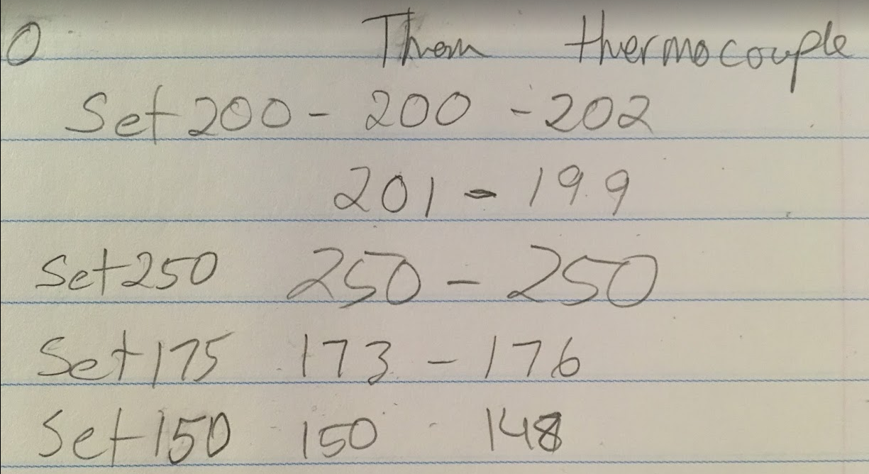
The good news is the thermistor table is working correctly from the marlin snap shot you provided. Thats with table 80. I connected a thermocouple to the hotend and tested a range of temperatures, at most it was off by 2 degrees when set to 200c.
NeoPixel works - lights up and changes colors when powered on.
I feel like this issue with the motors was already solved in a previous snapshot, I'm not sure if there are other changes that need to be made. I messed with microstepping settings and it still just squeaks instead of moving
The bad news is the stepper motors don't turn, they just squeal in place.
This is progress! I think we're almost done!
Here's a snapshot of the Marlin code for the G2 board. It has the LEDs defined and the custom thermistor table I defined. I arbitrarily called it 80.
Marlin.zipI did a quick test of the thermistor table and got theses results:
source       table 80       K     non-contact
melting ice     0.0         0
room temp      25.9        24      24
coffee cup    113          69      68
table 80 - measured by G2
K - using K thermocouple on my DVM
non-contact - IR thermometerLooks like either my calculations are off or the thermistor I had laying around wasn't an EPCOS 100K.
The real test is what it does when hooked up to a G2 printer. Once someone reports how it behaved in a real system then I can have some confidence in how to modify the table.
drphil3d
on 18 Mar 2019
The motor squealing means the step rate/acceleration/jerk is too high for the current/power supplied to the stepper.
Try doubling the current setting for the motors that are having the problem.
Only a 2C error at 200C? Amazing. At 200 C the resolution is about 2 degrees C.
How did you fix your compile error? I wasn't able to re-produce it. If you want me to look into it I'll need your configuration files and the pins_PRINTRBOARD_G2.h file.
Bob-the-Kuhn
on 18 Mar 2019
I tried changing the current and step rate/acceleration/jerk but didn't help. I'm thinking the microstepping got screwed up. I made some edits to the microstepping section but that didn't help.
Oh by the way enabling EEPROM and updating it flips the lock bits, which can be unlocked using that atmel utility.
I didn't fix the error I just used the snapshot you provided.
Marlin Snapshot 3-17-2019.zip
drphil3d
on 18 Mar 2019
Does this ZIP include you configuration files?
If yes then you need to change MICROSTEP_MODES and DEFAULT_PWM_MOTOR_CURRENT to match your system.
Bob-the-Kuhn
on 18 Mar 2019
I just ran across settings_Printrbot_Simple_1403.h and settings_Printrbot_Simple_1608.h. Do they accurately define the motors?
If yes then I'll take a shot at turning them into two sets of config files.
Bob-the-Kuhn
on 18 Mar 2019
Where did you get those ? They should be correct.
Philip Mally
3D Printing & Rapid Prototyping Services
530-205-3210
[email protected]
drphil3d
on 18 Mar 2019
They are in g2-master.
I'll start on making the config files
Bob-the-Kuhn
on 19 Mar 2019
Yes, that's definitely the right config. Awesome! Thank you :D
drphil3d
on 19 Mar 2019
Try these files.
PRINTRBOARD_G2.zip
The names in the settings files didn't match up well with the Marlin names.
- If the Marlin DEFAULT_MAX_FEEDRATE is the same as VELOCITY_MAX then us it as is. Those values seem realy high so I also have a set using SEARCH_VELOCITY.
- The steps per revolution didn't match up with the comments so I have a set for each.
- There wasn't an axis labelled extruder so I used the values from the A axis
All the changes I made have a // Printrbot Simple after them.
I wasn't able to do a sanity check on the values. My motors power up but they don't spin. I'll look into that after I get some sleep.
Bob-the-Kuhn
on 19 Mar 2019
Excellent, I'm ready to test it when its ready
Maybe the step and direction pins are swapped
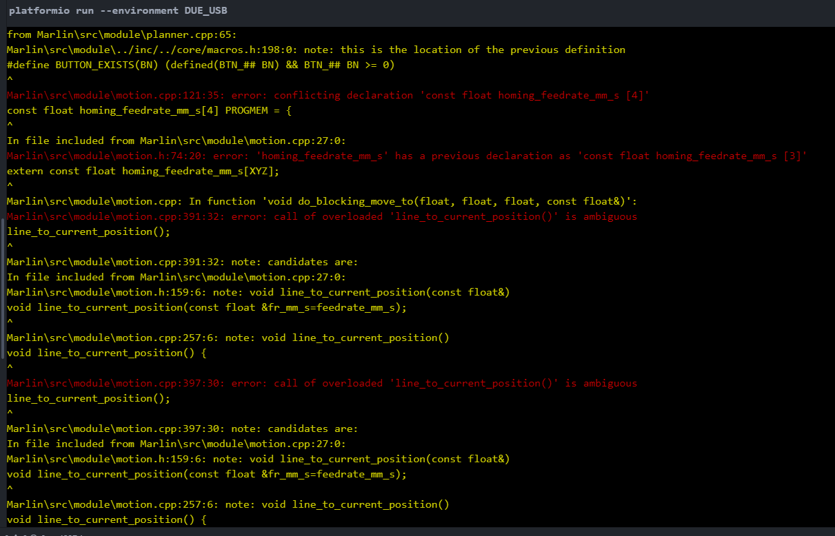
I did some digging around and found that the motion.ccp file didn't seem to be the modified version that you created. I added the modified file but it fails to compile.
I have a suspicion some of the codes you modified to get the motors working didn't make it into the latest version.
drphil3d
on 20 Mar 2019
Finally tracked down the stepper problem. Turns out the Neopixel library uses the same timer as the stepper. The quick solution is to just comment it out in configuration.h.
Here's an updated snapshot of the G2 code along with the thermistor tables.
Also included is the patched Neopixel library. If you want to play with the LEDs then enable it in configuration.h and replace the Neopixel library.
Bob-the-Kuhn
on 25 Mar 2019
Here's the G2 code with the changes I've proposed in PR #13481 to fix the Neopixel problem. With this code there's no need to modify the Neopixel library.
Bob-the-Kuhn
on 25 Mar 2019
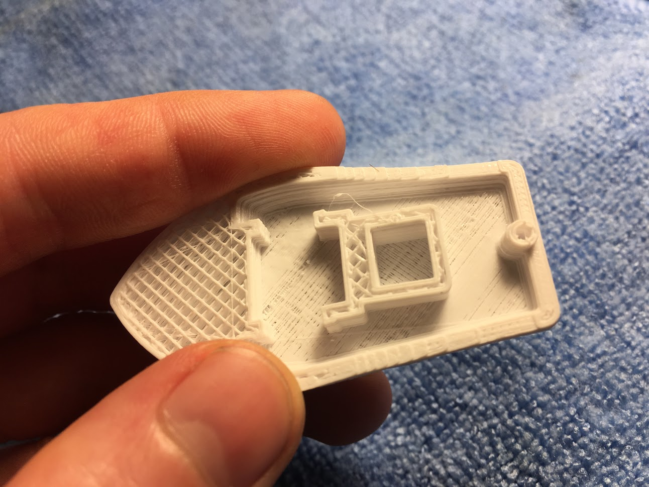
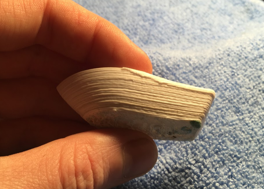
Good News! I did my first print, bad news it looks like crap.
Here is the source, I modified the config to fit the Printrbot Simple Pro which is not the 1408 or the 1608, those are older models, some things are close to correct.
I think the PWM frequency is not quite right for the stepper drivers. I hear a rhythmic beep noise every few seconds and the print quality is well garbage, but it works and thats progress!
I have the stepper drivers running very smoothly on Klipper firmware, but have not yet figured out an issue with the thermistor not reading the correct value.
This is the config form Klipper, I figure it may help.
Some other info about the stepper drivers
https://github.com/KevinOConnor/klipper/issues/1121#issuecomment-456855880
stepper driver current DRV8825
[output_pin motor_x_pwm]
pin: PB17
pwm: True
hardware_pwm: True
scale: 2.25
cycle_time=.000004
value: 0.8
[output_pin motor_y_pwm]
pin: PB19
pwm: True
hardware_pwm: True
scale: 2.25
cycle_time=.000004
value: 0.8
[output_pin motor_z_pwm]
pin: PB18
pwm: True
hardware_pwm: True
scale: 2.25
cycle_time=.000004
value: 0.8
If I remember correctly PA2 on the the E motor stepper driver does not have hard PWM.
[output_pin motor_e_pwm]
pin: PA2
pwm: True
scale: 2.25
cycle_time: 0.1
value: 0.8
Here is the entire config if you would like to see
G2 THermistor config ongoing issues AAAhhh.txt
drphil3d
on 26 Mar 2019
Also, can't seem to change any of the settings without the EEPROM option being enabled in marlin which seems to flip the lock bits.
If you want to program it again it must be cleared using using SAM-BA 2.1 https://www.microchip.com/developmenttools/ProductDetails/atmel%20sam-ba%20in-system%20programmer
drphil3d
on 26 Mar 2019
Nice looking prints are vastly over rated. 😉
I'll try to kick up the PWM frequency. I'll take a second look at enabling the hardware PWMs for the three.
Have you had a chance to check for lost steps or play with the current settings or the microstep settings?
How do you know the thermistor readings are off? I was using hot tap water to get an idea of the upper temperature accuracy. I found out that my tap water was too ionic and I'd get readings that were 30 - 50 C too high.
Bob-the-Kuhn
on 26 Mar 2019
Yeah, I check checked for missed stepps. I can hear this ping noise coming from the stepper motors regardless the motors moving or not.
Thermistor readings in Marlin work fine, I think its a underlying issue with klipper.
drphil3d
on 26 Mar 2019
I changed some settings that seemed to help. now I only hear the whining on certain micro steps.
define PWM_MR0 25000 // base repetition rate minus one count - 20mS
define PWM_PR 24 // prescaler value - prescaler divide by 24 + 1 - 1 MHz output
define PWM_PCLKSEL0 0x00 // select clock source for prescaler - defaults to 25MHz on power up
// 0: 25MHz, 1: 100MHz, 2: 50MHz, 3: 12.5MHZ to PWM1 prescaler
define MR0_MARGIN 200 // if channel value too close to MR0 the system locks up
extern bool PWM_table_swap; // flag to tell the ISR that the tables have been swapped
define HAL_G2_PWM_ISR void PWM_Handler()
extern volatile uint32_t PWM_ISR1_STATUS, PWM_ISR2_STATUS;
Update: Changing PWM Period from 100 to 4 micro seconds significantly quiets the stepper drivers
define PWM_PERIOD_US 4 // base repetition rate in micro seconds
4 microseconds would be 250,000 hertz which I believe is what the stepper drivers require
drphil3d
on 26 Mar 2019
Try this code.
I've made the X, Y & Z Vref signals directly controlled which should cut down considerably the jitter in the period and pulse width. E0 remains as ISR controlled.
I've set the period to 40uS (25KHz). If you want to try other settings then please do. The only caveat is the E0 Vref jitter increases and the linearity at the low end gets worse as the period decrases. I've set a minimum current of 250mA because of the low end linearity problems. If you If you drop the period by 1/2 then the minimum current will probably be 2x.
Where are we at on the thermistors? Do we have acceptable thermistor tables for the extruder and the bed? If yes, which ones are they?
Bob-the-Kuhn
on 30 Mar 2019
Thermistor is working great, I'm using table 80 for the extruder, I have not tested the bed yet but I would assume the same result.
One other thing, I fixed it in the last snapshot I uploaded but you may not be working with that version
Pins file - X and Y endstop pins are reversed
drphil3d
on 30 Mar 2019
I did not notice it. I'll change my copy.
Bob-the-Kuhn
on 30 Mar 2019
Soooooo Much Better! although now I hear a high pitch squeel
drphil3d
on 30 Mar 2019
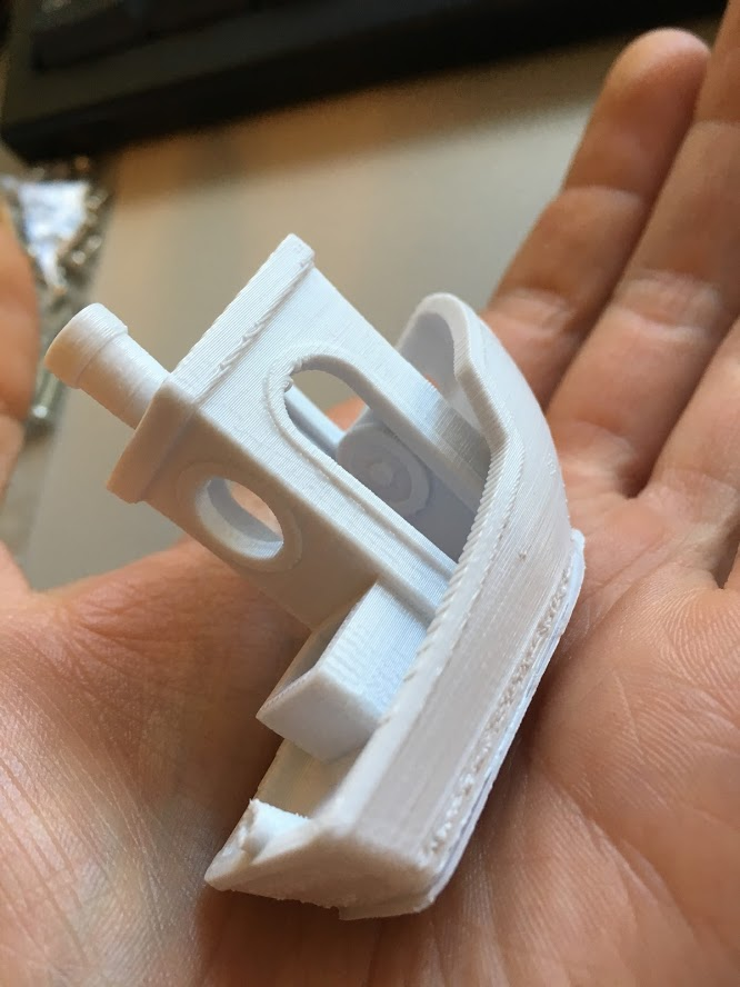
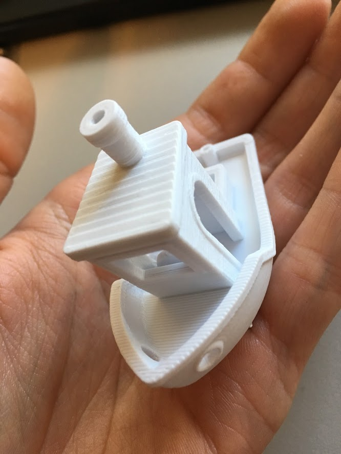
I'm printing a 3D benchy right now. Best quality yet
Edit: Well, I think we finally did it! I'm getting good quality and consistent extrusion, layers are consistent, print quality seems good. Although the extruder motor is emitting a very high pitch squeal.
Can motor current be set via gcode?
something strange I ran into when trying to run PID autotune, tempature does not increase and firmware goes into shutdown. I think this is probably because the 100hz to the global enable is not active while pid autotune is not running. not a big deal.
drphil3d
on 30 Mar 2019
Simplify 3D seems to generate far higher pitch noises from its gcode then cura. I think this firmware is ready for beta testing.
drphil3d
on 31 Mar 2019
Try dropping the period by 1/2 to see if the extruder squeal goes away .
If that doesn't do it then it's due to the jitter in the pulse location. The only mitigation is to increase the priority of the interrupt. Try reducing the numer in the middle on line 114 in G2_PWM.cpp. I'll start looking to see if I can identify the stepper priority level so it remains the higher priority.
NVIC_SetPriority(PWM_IRQn, NVIC_EncodePriority(0, 10, 0));
Are there any thermistor tables that should be dropped?
80 is for the extruder. Which one should I label as for the bed?:
I'll start getting rid of test items and bring the code up to date. I'll need you to provide the final configuration files and pins file.
Bob-the-Kuhn
on 31 Mar 2019
if you change the priority set it to 3. 2 is what the stepper ISR is. 3 is where the servo ISRs are. After that it's 14 for the tone interrupt.
Bob-the-Kuhn
on 31 Mar 2019
What is the official name of this system?
I'm assuming we want an example configuration and it should be called something that the user is familiar with.
Bob-the-Kuhn
on 31 Mar 2019
I think what I will do is release a precompiled bin file as well provide a
link to the Sam-ba program which you must run to flip the lock bit after
saving the eeprom. The processor locks when you send M502 followed by M500
for the first time, otherwise it stays unlocked.
I have a properly setup config file.
manufacturer: Printrbot
model: Simple Pro
The printrboard g2 was available as a replacement / upgrade controller but
I don’t know how popular that was.
I need to try some of the other tables, I tried setting the hotend temp to
231 and the printer shut down at 222 after not being able to reach that
temperature.
I was curious was the issue with the neopixel solved ? I remember you
saying it was a timer conflict.
drphil3d
on 31 Mar 2019
I'm not sure how to adjust the stepper driver current, is this done in the G2_PWM.h file? I need the stepper drivers running at about 1 amp.
Here is some information found regarding timer priority.
https://github.com/synthetos/g2/blob/7a25dbf1f8ab2e60ca6122b3a477d08b5b1cd8cc/g2core/stepper.cpp
https://github.com/synthetos/g2/blob/7a25dbf1f8ab2e60ca6122b3a477d08b5b1cd8cc/g2core/gpio.cpp#L240
https://github.com/synthetos/Motate/blob/41e5b92a98de4b268d1804bf6eadf3333298fc75/MotateProject/motate/Atmel_sam_common/SamTimers.h
But then as I was thinking about it, I remembered that @KevinOConnor was able to implement the sam3xc in Klipper and the drivers run super quiet and smooth. It may be a good idea to look at some of his code. https://github.com/KevinOConnor/klipper/blob/master/src/atsam/main.c
The /atsam folder covers the 3xc and e chips but he wrote a bunch of code specific for the sam3.
drphil3d
on 31 Mar 2019
It's in the pins_PRINTRBOARD_G2.h file.
#define DEFAULT_PWM_MOTOR_CURRENT { 1000, 1000, 1000} // XY Z E0, 250 - 3000mAh
Bob-the-Kuhn
on 1 Apr 2019
FWIW, Klipper programs the PWM hardware block on the sam3x8c to produce the X/Y/Z stepper reference voltage. So, it isn't taking any hardware irqs at all. The code's at: https://github.com/KevinOConnor/klipper/blob/master/src/atsam/hard_pwm.c
@Bob-the-Kuhn - I've seen reference to a temperature table 80 that works on the G2 - thermistor_80.h.txt. Do you know how that table was created?
-Kevin
 KevinOConnor
on 1 Apr 2019
KevinOConnor
on 1 Apr 2019
The last code I attached to this thread used the hardware PWM controlled pins for the X, Y & Z Vrefs. E0 is now the only Vref that is done via interrupts.
I had to go back and reconstruct how I created the temperature tables.
- 80 can be derived in two ways. One uses the EPCOS temperature/resistance charts for the Epcos
B57560G1104 thermistor. The other method takes thermistor table 1, calculates the temperature/resistance chart from it and then calculates the G2 version. - 81 is the thermistor table 1 method but with one of the resistors changed from the nominal 4.7K to the 4.36 that's on the board I have. It should be dropped.
- 94 is almost identical to 80. The notes on it says it started from the UBIS hot end. 94 should also be dropped.
- 82 is based the B57540G0104G000 thermistor table from EPCOS. It should be changed to use the nominal 4.7K resistor value.
- 91, 92 & 93 are the tables that result when using the three thermistors found in the current G2 code along with the G2 code's calculation methods. G2 uses the Steinhart-Hart three term equation to calculate temperature based on three observed resistance/temperature pairs.
Only table 82 is based the B57540G0104G000 thermistor. The references to it on the other thermistor tables need to be corrected.
Looks like need to do a little cleanup on the temp tables.
Here's the data sheets and Excel spread sheets this is based on.
G2 temp tables rev 2.zip
Here's the cleaned up tables and configuration.h:
thermistor tables cleaned up.zip
Bob-the-Kuhn
on 2 Apr 2019
although now I hear a high pitch [squeal]
I'm hearing this on a LPC1768 board extruding (probably with linear advance). Any good general troubleshooting tips for this issue will be added to the site. And of course we'll aim to get it solved in the firmware as far as possible.
 thinkyhead
on 11 Jul 2019
thinkyhead
on 11 Jul 2019
The G2's squeal comes from the PWM frequency of the digital stepper current PWMs. It's now set to a high enough frequency that the human ear can't hear it.
Bob-the-Kuhn
on 12 Jul 2019
@drphil3d it looks like a lot of good work went into this? Did you ever get it completely working?
 sjasonsmith
on 10 Nov 2020
sjasonsmith
on 10 Nov 2020
PR #13116 is the companion to this issue.
I was trying to find some more info on why this activity petered out but didn't find any smoking guns.
My memory is VERY fruzzy on this. I think the main problem areas were:
- Unable to figure out how to use the G2's smart LCD module
- Unable to figure out a method that the average user could use to move the Marlin code into the G2
Bob-the-Kuhn
on 16 Nov 2020
Related issues
 heming3501
·
4Comments
heming3501
·
4Comments
 Bobsta6
·
3Comments
Bobsta6
·
3Comments
 Matts-Hub
·
3Comments
Matts-Hub
·
3Comments
 StefanBruens
·
4Comments
StefanBruens
·
4Comments
 pubalan12
·
4Comments
pubalan12
·
4Comments