Hi
I want do decide wich bedleeveling method i should use.
It would help if you could answer folowing question:
Does UBL do the same vertical behavior as in thist video?
 Massa0815
All 31 comments
All of the mesh based bed leveling systems can handle that extreme tilt. The one thing you should consider is that the Z-Axis will not be normal to the bed for the mesh based systems. If you need the print to go up normal to the bed, you need to use the grid based leveling system.
 Roxy-3D
on 17 Jan 2019
Roxy-3D
on 17 Jan 2019
OK now I'm confused and I thought I understood most of this stuff. Can you provide a little more detail @Roxy-3D ? In particular which of the options in Marlin are "mesh" and which are "grid" also how does the grid based option give you a print that is normal to the bed? Does it need to modify the X and Y coordinates as well as Z?
 gloomyandy
on 17 Jan 2019
gloomyandy
on 17 Jan 2019
There is the original Mesh based system. There is UBL. And there is Bi-Linear. All 3 of those are mesh based. The 3-point and the grid based systems actually tilt the Z-axis normal to the bed. Both 3-point and grid based are the early bed leveling systems. Pretty much, people agree in the usual case, the bed is close enough to 'normal' that it is not necessary to compensate the Z-Axis.
But in that video you showed... It will become an issue.
Does it need to modify the X and Y coordinates as well as Z?
Yes. The 3-point and grid modify the X & Y coordinates as well as Z. The mesh based systems only compensate the Z.
Roxy-3D
on 17 Jan 2019
Ah that all makes a lot of sense. Thanks!
gloomyandy
on 17 Jan 2019
Thanks for your answers. Yesterday i tried to handle the UBL Leveling. But after some hours of failing, i returned to Biilinear leveling.
The problem was following:
I probed the bed with G29 P1. I saved the settings with G29 s1 and m500. Then i activated UBL with G29a. Now i tested the Nozzle distanze to the bed at every Corner and the midpoint. I had differences up to 0.5 mm. i tried the command G29j and the differences growed up to 2mm.
I repeated this a few times. Also with hot bed but it didn´t become better.
Yes i meassured the distance between nozzle and probe exactly. My probe can test up to 10 mm to the edge f the bed.
Ich switched back to bilinear and this worked.
Sorry for my bad english ;)
Massa0815
on 18 Jan 2019
What version of Marlin are you using? If you want further help with UBL you should do a G29 P1 and then post the output from G29 T. It would also be useful if you posted details of your printer (is it a delta or Cartesian) including your configuration files.
Having said that if you are happy with bilinear then maybe you should just continue using that.
gloomyandy
on 18 Jan 2019
OK . I use 1.1.9 cloned 3 days ago from Github on an arduino 256 with Ramps 1.4 and TMC2130 . Its a Printer similar to Prusa i3. It will take same days until i can post the P1 data because i have to give away this Printer to a friend of mine. I will build a second one on which i'll try it again. Thanks for your help.
Massa0815
on 18 Jan 2019
ok i tried it with the next printer. Again it dowsnt work. Here is my Mesh probing result
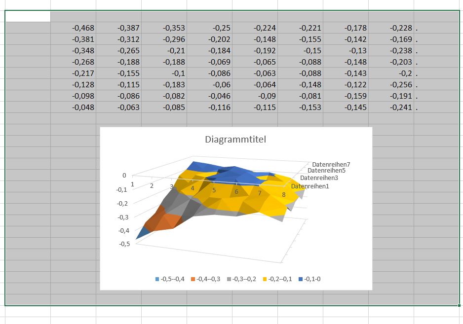
When i print the first layer, in the middle of the be, the nozzle is too near to the bed. Left and right of the bed its too far away so that the plastic doesnt stick. I see the Z motors mooving while nozzle is mooving from left to right. I dont know what my problem is.
I probed the bed at 70°C and i print at 70°C.
Probing:
G28
G29 P1
G29 S0
M500
Gcode Startscript:
Heating bed to 70°
G28
G29 L0
G29 A
then printing
Massa0815
on 20 Jan 2019
Can you post the actual output of G29 T (rather than the data in a spreadsheet). It looks like your mesh is not complete (there is a row of dots down the right hand side). Also are you sure that when you probed the bed you did the G28 after the bed was heated up and just before the G29 P1? It is unusual to see a mesh that has every value be less than zero like yours. You should also post your configuration files. What sort of probe are you using? Are you using the probe for homing?
gloomyandy
on 20 Jan 2019
Bed Topography Report:
( 1,199) (199,199)
0 1 2 3 4 5 6 7 8 9
9 | . . . . . . . . . .
|
8 | . -0.468 -0.387 -0.353 -0.250 -0.224 -0.221 -0.178 -0.228 .
|
7 | . -0.381 -0.312 -0.296 -0.202 -0.148 -0.155 -0.142 -0.169 .
|
6 | . -0.348 -0.265 -0.210 -0.184 -0.192 -0.150 -0.130 -0.238 .
|
5 | . -0.268 -0.188 -0.188 -0.069 -0.065 -0.088 -0.148 -0.203 .
|
4 | . -0.217 -0.155 -0.100 -0.086 -0.063 -0.088 -0.143 -0.200 .
|
3 | . -0.128 -0.115 -0.183 -0.060 -0.064 -0.148 -0.122 -0.256 .
|
2 | . -0.098 -0.086 -0.082 -0.046 -0.090 -0.081 -0.159 -0.191 .
|
1 | . -0.048 -0.063 -0.085 -0.116 -0.115 -0.153 -0.145 -0.241 .
|
0 |[ . ] . . . . . . . . .
0 1 2 3 4 5 6 7 8 9
( 1, 1) (199, 1)
I heated up and did G28 then G29 P1
Homing Z is done in X = 0 and Y = 0
My Sensor is an inductive one from Amazon
LJ12A3-4-Z/BX DC6-36V
Yes im using the probe for homing.
Here is my Configuration.h
Massa0815
on 20 Jan 2019
None of the edge grid points have been filled in (you can see the dots at the top, left, right and bottom). There are various ways to complete the mesh, but a quick and usually good approximation is to do a G29 P3.14 just before you save the mesh. It should help with the edges of your bed. You may find you get a better mesh if you home in the centre of the bed (Try setting Z_SAFE_HOMING), As this ensures there is plenty of metal for the probe to detect and avoids things like mounting screws etc. You may also need to fine tune your Z offset to get the initial nozzle height correct.
Oh and I find that doing a G29 J3 at the start of the print can also help if you have a bed than can move slightly (or a removable bed).
gloomyandy
on 20 Jan 2019
OK Thanks. I did what you said. I tried it at a third printer ( yes i build 5 printers momentarely).
G28 no homes at the center of the bed.
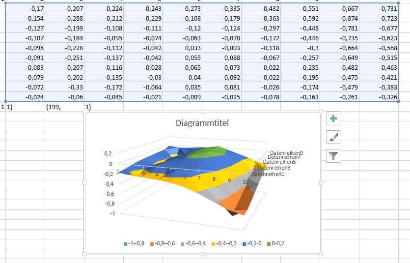
But when i execute G29 P3.14 the extrapolation does som weird things. It seems like it works inversed. It lifts the edges instead of lowering them. Look at the attached Picture.
Massa0815
on 20 Jan 2019
Sorry i accidentely closed it^^
Massa0815
on 20 Jan 2019
Well you can try G29 P3.11 or G29 P3.12, but all this is doing is making up values by fitting a line to nearby points to fill in the missing values. It seems to me to be doing a reasonable job looking at the output you have above. If you want it to be accurate your really need to either use the manual UBL probing mechanism or to print a test print and adjust the mesh manually (which is @Roxy-3D preferred way of doing things).
So a reasonable way of doing things is to adjust your Z offset so that you can print a small object in the centre of the bed without UBL active. Once you can do that, create a new mesh and check that you can still print in the centre of the bed with UBL active (you should be able to), then check points further away from the centre (perhaps by printing the UBL test pattern). You may need to fine tune points of the mesh during this process.
By the way I'm not sure that trying to investigate your problem on different printers makes a lot of sense.
If you are still having problems you may want to try using a larger value for MIN_PROBE_EDGE it could be that your probe does not function well close to the edge of the bed. Also what voltage are you operating the probe from? If 5V you may not be getting very accurate readings, some probes seem to be OK with 5V some not.
gloomyandy
on 20 Jan 2019
Where are the G29 P3.11 and 3.12 documented?
Massa0815
on 20 Jan 2019
I tried all the P3 Commands and the extrapolation works completely INVERS. The points at all edges should have a slope down. but the extrapolation does a slope upwards
Massa0815
on 20 Jan 2019
They take into account all of the points around a particular point (including the other points that have been estimated), this includes various diagonals . All of these are simply estimates to help you fill in the points that have not been probed. This result is usually a reasonable starting point. Perhaps for your mesh this is not the case. If you have accurate measurements then edit the mesh and fill in the missing values. If you don't like the estimates don't use them.
gloomyandy
on 20 Jan 2019
Can i particularly edit the points manualy? I want to set the value by myself
Massa0815
on 20 Jan 2019
But when i execute G29 P3.14 the extrapolation does som weird things. It seems like it works inversed. It lifts the edges instead of lowering them. Look at the attached Picture.
The fill algorithm is 'conservative'. If the bed is sloping upward, the extrapolated point is calculated from the existing points. If the bed is sloping downward, the nearest known point is used. (We don't want drive the nozzle into the bed!).
Can i particularly edit the points manualy? I want to set the value by myself
Yes... You can set a number with M421 to set an explicit number for a given mesh point. But usually an area needs to be adjusted, and the G29 P4 works easier to adjust the 5 or 6 points. You just park the nozzle over the center of the area and do a G29 P4 R and the nozzle will move to each mesh point and you can dial in how much higher or lower you want it. So, if you start in the center of the area, that mesh point usually will have the biggest adjustment, and as the nozzle works its way outward to the edge of the area, your corrections will usually be a smaller amount.
Roxy-3D
on 20 Jan 2019
I think the next ill doo is to slightly bend the Bed from convex to concarv ;)
Massa0815
on 20 Jan 2019
If you are printing on glass.... You could just flip the glass to change it from convex to concave.
But really... There should be no need. Just do a G26 mesh validation pattern, and edit the mesh points to be exactly correct.
Roxy-3D
on 20 Jan 2019
I have no glasbed on this printers. If i had glas i wouldnt have the problem with bended bed. I habe a aluminium heatplate 3mm thick. Under this plate i mounted 15 magnets to hold a metalsheet with PEI at the surface. Its similar to the Prusa MK3 solution. The Problem is, that the Aluminium Bed ist not 100% precisely plane. It has a Bending upwards. But if you say G29 P3 does only calculate slopes upwards at the edges i think i could bend the Bed slightely into the other direction (only 0,1 mm in the middle). I have built this printers for some friends of mine. And i need a simple procedure for them if they have to repeat the leveling. They are not experienced enough with 3D Printing to do some advanced procedures.
Massa0815
on 21 Jan 2019
As I said above the G29 P3 values are just a starting point, there is nothing to stop you from adjusting them downwards (if they actually need to go down, are you sure they do?).
You may want to do a G29 P1 on just the bed and on the bed with the sheet in place and compare the two, it may not be the bed that is not flat. But take care as an inductive probe will not detect an aluminium bed as well as it does a steel sheet (I know this because I also have a similar setup). Also check to make sure there is nothing between the sheet and the bed that could be causing the lift in the centre of the bed. Do you have magnets holding down the sheet in the centre of the bed? if not the sheet may be lifting when it gets hot. What temperature are you heating the bed up to? What type of magnets do you have? They may not .like being heated to anything much above 80C or so.
gloomyandy
on 21 Jan 2019
I am shure the edges have a slope downwards.
I have a full Grid of magneds over the whole bed. Also in the middle.
The magnets are for 150 °C and they are very strong. Neodym.
There is absolutely no obstacles between the aluminium bed and the steel sheet.
I can print PLA andd PETG (nothing else) at 70° bedtemperature.
Because of bed expansion under temperature i heat up the bed to 70°C before i do G29 P1.
Massa0815
on 21 Jan 2019
So have you actually run a G29 P1 on the bed alone and on the bed with the sheet in place?
Do you have a link to the magnets you are using (I need to get some more)?
So have you actually managed to create a mesh that works for you over the entire bed yet?
If you are not happy with the procedure for create a UBL mesh (which will require some way of handling the points on the mesh that can not be probed), but you are happy with biliner, perhaps you should just use bilinear?
gloomyandy
on 21 Jan 2019
Momentarely im at work ^^ i will do some more tests when i come home.
I am from germany and i only have a german link to to the supplyer of the magnets:
https://www.maqna.de/en/neodymium-magnets-disc/disc-10-19mm/neodym-scheibenmagnet-15x3mm-vernickelt-grade-n42sh-bis-150-c/a-2046/
If you mount the magnets with alternating polarity you can improve the force. The bed adheres very strong with 16 magnet in a 4x4 grid. I used an MK3 Aluminium bed with copper Side down and 2 cork sheets for isolation. in the first sheet i made holes for the magnets. I sticked the cork with Pattex to the bed. The Steel steet is a nickel coatet 0,7mm steel sheet. it costs 2,40 Euro ;)
The plastic coat on the sheet is this one:
https://www.ebay.de/itm/3D-Printing-Build-Plate-Tape-Surface-Printer-Heat-Bed-Platform-Sticker-Sheet-3/283340913058?hash=item41f86f39a2:g:5VsAAOSwAEFcPv1W:rk:2:pf:0
It works well. especially with PETG.
Massa0815
on 21 Jan 2019
Lol. I deletet the 3 codelines in ubl_G29.cpp witch prevent filling my missing downsloped meshpoints. And et-voilà..... it works.
Massa0815
on 21 Jan 2019
Excellent! Please consider this issue. Thanks
 shitcreek
on 23 Jan 2019
shitcreek
on 23 Jan 2019
Now after some tests with very flat parts i wanted to print higher things. A new problem occures. Two of my objects where printing well. But at the other testobjects i saw some strange things. I testet a while until i saw that the printer reached a height for example 6.4 mm. Then the next layer he printed at 5.8mm. This occures at different objects at different heights. I found out that it happens mostly at objects with a big bottom surface. Its not a problem of the mechanics. It occues with different printers with the same gcode at different heights. When i activate bilinear leveling, everything works fine. Because i had to deliver the other four printers to my friends, from now on i have only one printer left for testing. I will deliver some pictures, configuration and Gcode File when i come back home. At the momemnt i am on work.
Massa0815
on 28 Jan 2019
@Massa0815 problem solved?
 boelle
on 21 Feb 2019
boelle
on 21 Feb 2019
This issue has been automatically locked since there has not been any recent activity after it was closed. Please open a new issue for related bugs.
![github-actions[bot] picture](https://avatars2.githubusercontent.com/in/15368?v=4&s=40) github-actions[bot]
on 17 Jul 2020
github-actions[bot]
on 17 Jul 2020
Related issues
 spanner888
·
4Comments
spanner888
·
4Comments
 StefanBruens
·
4Comments
StefanBruens
·
4Comments
 Kaibob2
·
4Comments
Kaibob2
·
4Comments
 Glod76
·
3Comments
Glod76
·
3Comments
 otisczech
·
3Comments
otisczech
·
3Comments
Most helpful comment
There is the original Mesh based system. There is UBL. And there is Bi-Linear. All 3 of those are mesh based. The 3-point and the grid based systems actually tilt the Z-axis normal to the bed. Both 3-point and grid based are the early bed leveling systems. Pretty much, people agree in the usual case, the bed is close enough to 'normal' that it is not necessary to compensate the Z-Axis.
But in that video you showed... It will become an issue.
Yes. The 3-point and grid modify the X & Y coordinates as well as Z. The mesh based systems only compensate the Z.