Marlin: [BUG] S-Curve Acceleration - Velocity Jumps when changing direction
Hi,
The S-Curve Acceleration seems to work pretty well, but there's a velocity jump when an axis changes direction (or when an axis stops and starts again, but that's less likely to cause a resonance/missed step problem).

Zooming in shows a significant instantaneous spike in step time (from -2700 steps per second to +250 steps per second).

I see this with a clean build of the bugfix-2.0.x branch (Nov. 20), and my configuration is a stock Teensy++2.0 target with the following changes:
#define DEFAULT_MAX_ACCELERATION { 100, 100, 100, 100 }
#define DEFAULT_MAX_FEEDRATE { 300, 300, 300, 25 }
#define DEFAULT_AXIS_STEPS_PER_UNIT { 80, 80, 80, 500 }
#define S_CURVE_ACCELERATION
 xenovacivus
All 53 comments
The strange thing is that on the position trace, no discontinuity is shown. Make sure it is not a numeric instability (finite precision) on the either capture process or differenciation process...
 ejtagle
on 20 Nov 2018
ejtagle
on 20 Nov 2018
The data is captured with a logic analyzer watching the step and direction pins. The position is incremented on step with dir=1 and decremented on step with dir=0. So we wouldn't expect a discontinuity. The velocity curve is created from the difference in position, then applying a low-pass filter.
The number of steps is correct; it's the dramatic change in step period that's the problem.
xenovacivus
on 21 Nov 2018
Is this an unexpected interaction between s-curve acceleration and adaptive step smoothing?
 thinkyhead
on 21 Nov 2018
thinkyhead
on 21 Nov 2018
No, i really doubt it @thinkyhead . The logic analyzer does not capture Stepper ISR rate - It captures the step and dir pulses created by that ISR. Step smoothing improves positioning, but does not increase speed of step/dir pulses.
The strange thing about this graph is that the discontinuities on velocity and acceleration happen when there is essentially no movement. That is what calls my attention, Such huge jump in speed.
This could be caused by the JERK setting, that allows discontinuities in speed when transitioning of movements, or by the fact that this is plotting just one axis, and this could be a compound movement, where what matters is the vectorial velocity and acceleration changes (module of speed and acceleration) and not the change in its components...
ejtagle
on 21 Nov 2018
Also I don't have step smoothing defined.
//#define ADAPTIVE_STEP_SMOOTHING
Here's another example:

(Also good news - no steps are lost while changing direction)
The jumps in velocity in this test are +-800 (and +-80 for Z), which correlates with the "DEFAULT_JERK" settings in Configuration.h. So this looks (almost) like expected behavior - except that "DEFAULT_JERK" is defined as the maximum instantaneous speed change - and here, when going from a negative velocity to positive velocity, there are two back-to-back instantaneous changes (one from -800 to 0, then another from 0 to 800). So it's twice "DEFAULT_*JERK".
Here's a zoom of the velocity graph (unfiltered):

It's running this gcode:
M17 ; Enable Steppers
M121 ; Disable endstop checking
G92 X0 Y0 Z0 E0 ; Set Position
G1 F6000 ; Speed 100mm/sec
G1 X1
G1 X0
G1 X1
G1 X0
G1 X1
G1 X0
G1 X1 Y.1 Z.2
G1 X0 Y.2 Z.4
G1 X1 Y.3 Z.6
G1 X0 Y.4 Z.8
G1 X1 Y.7 Z.9
G1 X0 Y1 Z1
G1 X1 Y1.4 Z.9
G1 X0 Y.6 Z.8
G1 X1 Y.4 Z.7
G1 X0 Y0 Z0
G1 X1
G1 X0
G1 Y1
G1 Y0
G1 Z1
G1 Z0
G1 Y1
G1 X0 Y0
xenovacivus
on 21 Nov 2018
I have the creality cr10 printer and print a model with Marlin 1.1.9 and after 3 hours of printing that model the print starts to shows layers mismatched, change a little the position and print in different part, I do the same print three times and the same problem, I rollback to the original firmware that came with the printer and print again and no problem, maybe a problem with the s-curve? Please help me
 johanmga
on 1 Dec 2018
johanmga
on 1 Dec 2018
@johanmga, I've discovered the velocity jumps here come from using "classic jerk" computations, and happen whether or not s-curve acceleration is enabled.
Try uncommenting //#define JUNCTION_DEVIATION in Configuration_adv.h; that will disable classic jerk and use the junction deviation math instead.
Also for reference, issue #12403 is actively tracking the layer shift issue (please comment there too if you have more information on problems/solutions), and #12540 is has more information on classic jerk vs. junction deviation.
xenovacivus
on 1 Dec 2018
@johanmga, I've discovered the velocity jumps here come from using "classic jerk" computations, and happen whether or not s-curve acceleration is enabled.
Try uncommenting
//#define JUNCTION_DEVIATIONin Configuration_adv.h; that will disable classic jerk and use the junction deviation math instead.Also for reference, issue #12403 is actively tracking the layer shift issue (please comment there too if you have more information on problems/solutions), and #12540 is has more information on classic jerk vs. junction deviation.
thanks a lot!! i will try and comment in the near future the results, have a nice day :)
johanmga
on 2 Dec 2018
@xenovacivus I replaced the traditional jerk for junction deviation and the problem was solved!! , Additionally I put a little Pieces of foam on each corner of the printer in order to reduce the vibration :)
johanmga
on 3 Dec 2018
@xenovacivus, my morbid curiosity wonders what your captures look like with JUNCTION_DEVIATION defined :)
 fiveangle
on 4 Dec 2018
fiveangle
on 4 Dec 2018
They're pretty interesting, actually!
With the same configuration as the first post but JUNCTION_DEVIATION on and set to 0.02, I get this (S_CURVE_ACCELERATION on):

And here's the same input, but with S_CURVE_ACCELERATION turned off:

In the trapezoidal acceleration case, the first move (from 0 to 1600 steps) accelerates for roughly 1 second, coasts for a second, and then decelerates for a second. But in the s-curve acceleration case, it coasts for about 1.2 seconds and doesn't have enough time (travel length) to decelerate completely, resulting in the jump to 0 velocity. So either the s-curve is taking longer to accelerate/decelerate than the trapezoidal curve, or the time to begin decelerating is further into the block than with the trapezoidal profile.
Also gcode for reference:
M17 ; Enable Steppers
M121 ; Disable endstop checking
G92 X0 Y0 Z0 E0 ; Set Position
G1 F6000
G1 X-200
G1 Y50
G1 X200
G1 X-200
G1 Y50
G1 X0 Y0
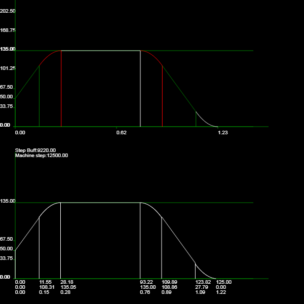
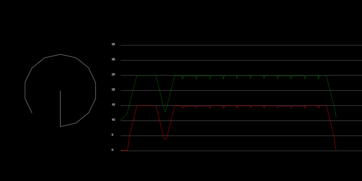
Here's a bit more!
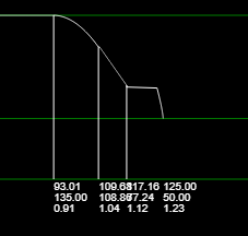
I aligned the s-curve and trapezoidal profiles with the same time scale and used the ms-paint analytical tool to compare. It looks like the s-curve for deceleration begins a little late, meaning the extra length traveled (area underneath the velocity curve) needs to be chopped off of the end, or the axis will travel too far. Because of the whole area-under-the curve thing, a little time spent at high velocity translates into a LOT of time spent at a low velocity (especially because the tail end of the s-curve is very near to zero). The green color tries to highlight this (the two areas are roughly equal; in fact, the tall skinny one should probably be a little skinnier).
Note: if the s-curve begins a little early, it results in a profile which stops short of the intended location. This is even less ideal than a profile that must be cut off, because the axis decelerates to zero and must accelerate again to complete the move (and that would require a lot more logic than the current "We're at the end of the travel, shut 'er down!"). So, if there must be some error, it's probably better to bias it to starting the deceleration curve a bit late.
A more optimal solution might re-evaluate the tail end of the s-curve on the fly and dynamically adjust, or just replace the last portion of the curve with a constant acceleration portion. Or, ideally, the point at which deceleration begins is precise.

xenovacivus
on 5 Dec 2018
@xenovacivus
What I gather from your last two comments: this is an issue with S-CURVE acceleration that is NOT fixed by enabling Junction Deviation, correct? S-CURVE acceleration profile either accelerates too slowly or decelerates too slowly, leaving an abrupt deceleration at the tail end of the S-Curve.
Earlier in the thread, there was some indication this problem was due to traditional JERK and resolved by enabling Junction Deviation. Am I correct in assuming that theory is no longer valid?
 gururise
on 5 Dec 2018
gururise
on 5 Dec 2018
It would give more insight if we could measure the timing of step pulses at the place where the discontinuity in acceleration happens... 👍
ejtagle
on 5 Dec 2018
@gururise: yep, this is a problem with s-curve acceleration which is not solved by enabling JUNCTION_DEVIATION. Classic jerk computations add another velocity spike (dependent on MAX_JERK) but this one is independent of that.
Here's a zoomed in view of the steps and velocity at the first velocity jump:

Steps/s is exactly 1/(time between steps), so you can invert again to get the actual time. In this case, the last step took 457.62us.
There's a standalone plotly .html file with all the detail here, you can zoom and pan into whatever section is interesting:
https://drive.google.com/open?id=1ctZzgsAGRkxphIrj3MbXOTcP7zb2B6AN
xenovacivus
on 5 Dec 2018
I am trying to figure out the problem:
The S-Curve implementation just fits the SCurve to the trapezoidal curve (that internally is still used to do planning)
The first thing i thought was that the delay in the deceleration of the SCurve was caused by some problems on the calculations themselves, but, as you pointed out, probably this is not the case.
My suspicion, right now, is rounding errors. And maybe the solution to them are not so complex. Let me explain how the stepper routines work:
1) The count of steps to apply is independant of the acceleration profile. The idea is just to compute the delay between steps to create the proper acceleration profile.
2) So, even if the acceleration profile is not completely evaluated (as you have seen, it is truncated at the end), there should never be missing steps or extra steps.
3) Each time a "step" is output, a delay (in clock cycles) to the next step is computed, and that delay is used to program a timer that will delay the next ISR that will create the next step pulse.
4) The bezier curve is a function of time, and time is just the accumulated "clock cycles" from the previous pulses.
This is the trapezoidal algorithm
acceleration_time = 0
acceleration_steps_to_do = 1000; // Count of steps to do for acceleration
while (acceleration_steps_to_do  > 0 ) (
 create_step_pulse();
 step_rate= acceleration_time * acceleration_rate + initial_rate; // in steps per second
 delta_cycles = CLOCK_SPEED_HZ/step_rate
 acceleration_time = acceleration_time + delta_cycles
 delay_cycles(delta);
 acceleration_steps_to_do  = acceleration_steps_to_do - 1;
}

cruise_steps_to_do = 1000; // Count of steps to do for cruise
while (cruise_steps_to_do  > 0 ) (
 create_step_pulse();
 delay_cycles(delta); /* we reuse the last delay here */
 cruise_steps_to_do  = cruise_steps_to_do - 1;
}

deceleration_time = 0
deceleration_steps_to_do = 1000; // Count of steps to do for deceleration
while (deceleration_steps_to_do  > 0 ) (
 create_step_pulse();
 step_rate= cruise_rate - deceleration_time * deceleleration_rate; // in steps per second
 delta_cycles = CLOCK_SPEED_HZ/step_rate
 deceleration_time = deceleration_time + delta_cycles
 delay_cycles(delta);
 deceleration_steps_to_do  = deceleration_steps_to_do - 1;
}
This is the SCurve algorithm
acceleration_time = 0
acceleration_steps_to_do = 1000; // Count of steps to do for acceleration
calculate_scurve_coeffs(initial_rate, cruise_rate, acceleration_time);
while (acceleration_steps_to_do  > 0 ) (
 create_step_pulse();
 step_rate= evaluate_scurve(acceleration_time); // in steps per second
 delta_cycles = CLOCK_SPEED_HZ/step_rate
 acceleration_time = acceleration_time + delta_cycles
 delay_cycles(delta);
 acceleration_steps_to_do  = acceleration_steps_to_do - 1;
}

cruise_steps_to_do = 1000; // Count of steps to do for cruise
while (cruise_steps_to_do  > 0 ) (
 create_step_pulse();
 delay_cycles(delta); /* we reuse the last delay here */
 cruise_steps_to_do  = cruise_steps_to_do - 1;
}

deceleration_time = 0
deceleration_steps_to_do = 1000; // Count of steps to do for deceleration
calculate_scurve_coeffs(cruise_rate, end_rate, deceleration_time);
while (deceleration_steps_to_do  > 0 ) (
 create_step_pulse();
 step_rate= evaluate_scurve(deceleration_time); // in steps per second
 delta_cycles = CLOCK_SPEED_HZ/step_rate
 deceleration_time = deceleration_time + delta_cycles
 delay_cycles(delta);
 deceleration_steps_to_do  = deceleration_steps_to_do - 1;
}
The main problem with that algorithm is that all variables are integers, so errors accumulate along movements.
What calls my attention is that there seems to be an extra delay on the cruise phase, or perhaps the problem is a rounding error on the start of the deceleration phase, as the faster the movement is, the less precise the step_rate variable becomes, as that variable is an integer... And that could lead to deceleration_time increasing at an slower pace than required, and thus the "delay" in the start of the scurve deceleration profile
ejtagle
on 5 Dec 2018
I just tried S-curve and junction deviation on with 0.02, and got some missed steps/skipping belts/noise etc. I'm using a Rumba+ and DRV8825 drivers. Rather large printer though so the mass of the carriage doesn't help. having s-curve really working would be awesome! Great work on the above graphs, very nice.
Could you use a round or floor or ceil type function, or split up the section of travel that needs the s-curve computation into more sections, and then set a requirement for the position, vel, accel to line up at the intersection of those sections? Then you could apply a numerical adjustment in each section to ensure accel at end of movement goes to zero? Or maybe do the calculation in reverse and let the starting point have the error rather than the end of the travel?
Just some ideas...
DroneMang
 DroneMang
on 6 Dec 2018
DroneMang
on 6 Dec 2018
@DroneMang : There is a known problem with DRV8825 and 32bit boards. Please, increase the minimum pulse width to 3 or 4us and your skipped steps will be solved.
ejtagle
on 6 Dec 2018
@ejtagle, good observation, accumulating into an integer (always with floor behavior) will result in a lower acceleration_time than should actually be supplied to the curve function.
In the worst case scenario on a travel with 16,000 steps, it could be short by up to 16,000 "units". With 80 steps/mm and 100mm/s^2 acceleration, I get 1970000 for the "acceleration_time" (time duration for the acceleration/deceleration curve). 16,000 is ~0.8% of 1970000, so while that contributes, I don't think it's the only culprit (though, with all the details thrown in, perhaps it can be short by more than 1 unit per step).
Another culprit is the "get_period_inverse" function in planner.cpp, which returns 0x1000000 / d as an integer (not rounding, just using floor it looks like). So if it's fed the acceleration_time of 1970000, it returns 8, but the real ratio is 8.52. The value returned is used to compute the s-curve duration, so if it's low, the s-curve will effectively be computed for an acceleration_time of 2097152. If target speed is higher, the potential error is even worse.
For example, with the default acceleration of 100mm/s^2 and 80 steps/mm, this gcode produces a s-curve that's chopped off at nearly 6000steps/s (or 75mm/s):
; Reaches ~11K steps/second
; With ACC = 300mm/s^2 and 80 mm/step,
; s-curve deceleration stops at ~5745 steps/sec.
M17 ; Enable Steppers
M121 ; Disable endstop checking
G92 X0 Y0 Z0 E0 ; Set Position
G1 F18000
G1 X200
G1 X0

So maybe a heavy handed solution would be increasing the resolution of the "*time_inverse" variables (which probably means a re-write of the s-curve assembly code...).
xenovacivus
on 6 Dec 2018
I wonder if a 32bit system would produce any insights into this problem? Does this same problem exist on 32bit boards? Has anyone been able to create the same traces for a 32bit system? Would it be easier to test any solution on a 32bit system?
 gloomyandy
on 6 Dec 2018
gloomyandy
on 6 Dec 2018
@gloomyandy : On 32bit systems, the accumulated error is less, just because the timer runs at a higher frequency. But i did never test if the acceleration curve is chopped...
@xenovacivus : Perhaps it would be desirable to round up... ? - Having a faster Scurve, besides pushing a little bit the maximum speed of the motors, would not get any discontinuity.
I am not a fan of increasing the resolution of the calculations. AVR is struggling to get the SCurve computed in realtime, and, in fact, when i wrote those routines, i had to reduce precision as much as possible to get it to run in realtime.
But rounding UP the result of get_period_inverse() is perfectly doable. Also rounding up the Scurve computation should be no problem... Perhaps something along that idea could work...
ejtagle
on 6 Dec 2018
@DroneMang : There is a known problem with DRV8825 and 32bit boards. Please, increase the minimum pulse width to 3 or 4us and your skipped steps will be solved.
The Rumba+ is 8-bit, but Arduino IDE says:
Sketch uses 184080 bytes (72%) of program storage space. Maximum is 253952 bytes.
Global variables use 5311 bytes (64%) of dynamic memory, leaving 2881 bytes for local variables. Maximum is 8192 bytes.
So I think it should be able to run it. Maybe junction deviation and s-curve actually is too much though.
I'm waiting for the Revolve and Smoothieboard V2 Kickstarters to step up to 32-bit.
Linear Advance works great, and produces S-curve like movements when extruding, how does s-curve mesh with linear advance nowadays? S-curve would be nice for non-printing moves, perhaps an option could be introduced to use s-curve only for non printing moves, then you can skip the linear advance calculations for those moves?
DroneMang
DroneMang
on 6 Dec 2018
@xenovacivus problem solved?
 boelle
on 21 Feb 2019
boelle
on 21 Feb 2019
I don't think there's been any update to the related code (if there is, I'd be happy to test it!).
xenovacivus
on 26 Feb 2019
bugfix 2.0 is updated almost every 2nd day so i think it has been
boelle
on 26 Feb 2019
Based on the later comments, I believe I was able to reproduce this on a week old bugfix-2.0.x. I essentially did M204 T50 to get a very low acceleration when moving the bed around with wobbly parts and when doing a fast G1 move across the whole bed travel distance of ~300mm, it accelerates fine, moves fine, starts slowing down as expected and, in the middle of deceleration, stops suddenly.
This happened on RAMBo (8bit) @ 24V, disabling S_CURVE_ACCELERATION "fixed" it.
 comps
on 26 Feb 2019
comps
on 26 Feb 2019
You may just be pushing the processor too hard. S_CURVE_ACCELERATION is hand-tuned assembler on AVR and yet still does use up a lot of time in processing. Do you ever see issues with lower movement rates? You may also want to try ADAPTIVE_STEP_SMOOTHING to see if it keeps the load down.
thinkyhead
on 3 Mar 2019
You may just be pushing the processor too hard.
S_CURVE_ACCELERATIONis hand-tuned assembler on AVR and yet still does use up a lot of time in processing. Do you ever see issues with lower movement rates? You may also want to tryADAPTIVE_STEP_SMOOTHINGto see if it keeps the load down.
If you're referring to my issue, then I don't think it's a CPU issue - I do have those, but that usually results in stutter in movement, the decelleration here is part of a single-gcode move and is cut short prematurely and never finished (though the position seems to be correct according to the DRO on an LCD display, so no steps lost). The effect is less noticeable on slower feedrates (default F3000, noticeable even on F1000), but is still there. I run with ADAPTIVE_STEP_SMOOTHING enabled.
If it seems unrelated to this issue, I can create a new one.
comps
on 3 Mar 2019
Could it be that the issue stems from these lines:
// Steps required for acceleration, deceleration to/from nominal rate
uint32_t accelerate_steps = CEIL(estimate_acceleration_distance(initial_rate, block->nominal_rate, accel)),
decelerate_steps = FLOOR(estimate_acceleration_distance(block->nominal_rate, final_rate, -accel));
// Steps between acceleration and deceleration, if any
int32_t plateau_steps = block->step_event_count - accelerate_steps - decelerate_steps;
The steps required for acceleration and deceleration are calculated on a trapezoidal movement, but s-curve inherently needs more time for acceleration and deceleration, doesn't it?
 microtronics
on 6 Aug 2019
microtronics
on 6 Aug 2019
@xenovacivus did you retest with latest bugfix 2.0.x ?
boelle
on 28 Aug 2019
I dusted off my Teensy++2.0 and pulled the latest code; the results look exactly as they did in November 2018:
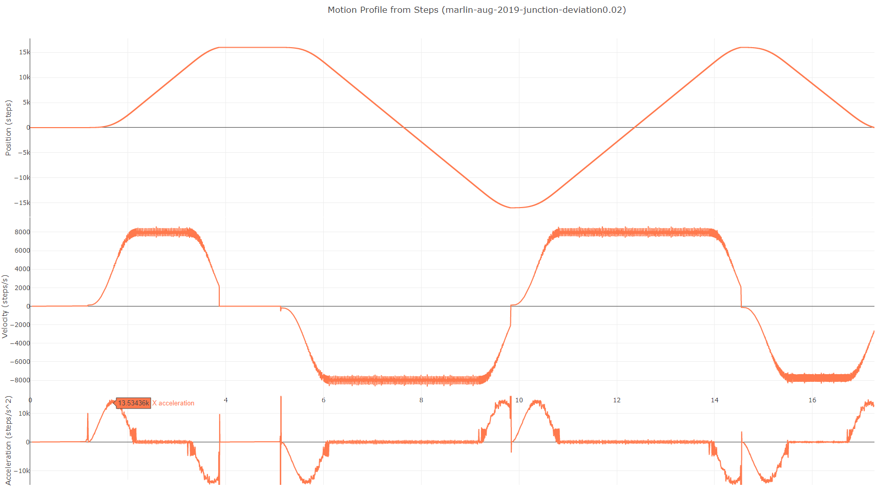
This is the same JUNCTION_DEVIATION and S_CURVE_ACCELERATION enabled configuration posted above. Keep in mind I am running this on an 8 bit AVR, and the 8 bit code has reduced computation accuracy to keep it fast. A 32 bit microcontroller should produce more accurate start/stop times for the s-curves (maybe I'll test with one of those soon...).
@microtronics: given the same maximum acceleration, yes, an s-curve will take more time to complete than the equivalent trapezoidal profile. In this approach though, the s-curves are computed to take the same time as an equivalent trapezoidal - stretching max acceleration as required to get to the target velocity. With an acceleration set to 8000 steps/second^2 (100mm/s^2 and 80 steps/mm) and S_CURVE_ACCELERATION on, the effective maximum acceleration is somewhere ~14,000 steps/second^2. In theory, a smoother acceleration profile will reduce transient vibrations and allow higher acceleration. In practice, definitely run some new max acceleration tests if you've enabled S_CURVE_ACCELERATION :)
xenovacivus
on 29 Aug 2019
@xenovacivus i assume this is still a problem?
boelle
on 24 Sep 2019
Lack of Activity
This issue is being closed due to lack of activity. If you have solved the
issue, please let us know how you solved it. If you haven't, please tell us
what else you've tried in the meantime, and possibly this issue will be
reopened.
boelle
on 12 Oct 2019
@boelle this is the reason junction deviation was just made the default.... This is absolutely still present. This needs to be reopened.
 InsanityAutomation
on 15 Oct 2019
InsanityAutomation
on 15 Oct 2019
@boelle this is the reason junction deviation was just made the default.... This is absolutely still present. This needs to be reopened.
Worth pointing out that non-cartesian printers can't use junction deviation, so if JD was enabled by default to fix some issues then these issues are still going to be present on e.g., deltas.
 Knifa
on 30 Oct 2019
Knifa
on 30 Oct 2019
@xenovacivus is this still a problem with the latest download of 2.0.x?
boelle
on 16 Nov 2019
interesting... i have been study how to implement true "jerk" for weeks, maybe you guys can see it here.
http://172.245.97.171/static/tes1copt.html
i think it can be implemented in 32bit processor...
all equation are in the html/javascript.
 ryannining
on 20 Nov 2019
ryannining
on 20 Nov 2019
Nice. But numerically a bit unstable. From the initial values change Vexit to for example 50.
 AnHardt
on 20 Nov 2019
AnHardt
on 20 Nov 2019
I'm not sure if I found something. I compared the time calculation in Marlin with the TinyG implementation for S-Curve
Marlin:
acceleration_time = ((float)(cruise_rate - initial_rate) / accel) * (STEPPER_TIMER_RATE)
TinyG: The math for time-to-decelerate T from speed S to speed E with constant jerk (I think this means acceleration)
T = 2*sqrt((S-E)/J[n])
I'm not sure but could it be that marlin calculates the time wrong?
 Strahler85
on 20 Nov 2019
Strahler85
on 20 Nov 2019
I'm not sure if I found something. I compared the time calculation in Marlin with the TinyG implementation for S-Curve
Marlin:
acceleration_time = ((float)(cruise_rate - initial_rate) / accel) * (STEPPER_TIMER_RATE)TinyG: The math for time-to-decelerate T from speed S to speed E with constant jerk (I think this means acceleration)
T = 2*sqrt((S-E)/J[n])
I'm not sure but could it be that marlin calculates the time wrong?
that marlin is Constant acceleration
since Vf = Vi + A.T
so T = (Vf-Vi)/A
I was using tinyG for inspiration and initial work for that test1copt.html code.
But then i decide to learn the correct Math for Constant Jerk (linear Acceleration). Then try optimize it, and later need to figure out how to work it on step generator on CNC/3d firmware.
And you can check the test1copt.html code, there is segment 1 calculation where we need to know time to reach the maximum acceleration from a constant jerk value (initial acceleration is 0)
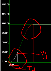
A = A0 + J.T
A0 is zero because head s-curve acceleration start at 0
so
T = A/J -> lets call it Tj
and we found the V at that T is
V=A0.T + 1/2.J.T^2 -> A0 is zero
V=1/2.J.T^2 -> lets call it Vj
But if the Vcruise-Vinitial cannot satisfy 2xVj ( for head and tail of the S-Curve) we need to adjust Vj, so the head and tail of curve will meet in the center and no Constant Acceleration Segment.
Vj = (Vcruise-Vinitial)/2
Tj = sqrt(2*Vj)/J
I have read code on Marlin, Repetier , GRBL about how they generate step data to Timer. They all are my inspiration on creating Karyacontroller 3d/CNC firmware.
And will try to add this true Jerk feature later after i can implement it on Karyacontroller firmware.
Since Karyacontroller is now little bit different step generator, it generate a step buffer and the Timer read from this buffer. So the main step generator runtime can generate as much segment/line to buffer and when it need to do initial calculation on new line segment, the step buffer still have movement data for hundreds steps ahead. So step generator can have more longer initial calculation time.
ryannining
on 20 Nov 2019
@ryannining: awesome stuff! I wrote an s-curve utility too, mostly to investigate how different motion profiles interact when moving a mass through a spring: https://xenovacivus.github.io/motion-control/curve-simulator.html
Also, as I understand it, the Marlin s-curve logic is based on the TinyG. And the TinyG controller doesn't implement constant jerk s-curves; instead, it uses a bezier curve of step_rate(time). So the motion profile will have a "smooth" jerk profile, instead of a square-step jerk profile.
I like that your curve computer handles initial and terminal velocity parameters - that's important when joining multiple curves together (circles broken into lines, for example). It's also possible to compute a curve with a non-zero initial/final acceleration, but things get complex fast there. Testing, hopefully automated, would really help out when it comes to motion and path planning algorithms. Maybe a set of path-planning tests could even be shared with the Marlin project too...
The "step buffer" is also a great idea - I've got some firmware of my own that buffers the steps between computation and step output; this allows for sub-microsecond accuracy on step pulses and reduces the worst-case timing requirement on step computation speed. Another approach is to forgo the step/direction interface all together, and use an IC which transduces a voltage input to a current output (like the MTS2916A), and create a sinusoidal voltage using a filtered PWM output. Then the microcontroller only needs to compute position(time) instead of time(position). Computing the position for a given time is a straight-forward multiplication and addition; computing time for a given position involves solving a quadratic equation (for trapezoidal curve profiles) or a cubic equation (for s-curves).
And yes, it is possible to implement mathematically accurate s-curve motion profiles on a microcontroller with accurate path planning and reliable step generation beyond ~50Khz on 3 axis (depending on the speed of the MCU).
xenovacivus
on 21 Nov 2019
at first i try implement smoothing by averaging the timer buffer. Timer function will read 5 (or more sample to smooth more) from the timer buffer and avarage it. But its looks wrong, thats when i start learning the tinyG and the constant jerk.
I already make the demo here:
http://172.245.97.171/static/tes1.html
its contain trapezoid constant acceleration path planning, junction deviation, and a function to call to add line path to buffer. It will display the machine X and Y position in the graph too.
addmove(F,X,Y,Z,E); // 4 axis
The graph is good, but i am not satisfied with the method, because its fake. So i havent test this step generator on Arduino.
I usually use javascript first to develop and test my code before apply it to Arduino
ryannining
on 21 Nov 2019
@xenovacivus so you still have an issue?
boelle
on 24 Nov 2019
Hi @xenovacivus i have update my javascript test, its almost complete now.
the implementation of constant jerk motion
I think the implementation is so simple that 1 function can work for all phase (constant jerk, constant acc, constant velocity)
No need to squareroot the velocity (it save V in normal state, not squared state).
var lsteps = 0;
var mi = 0;
function machinemove(sg,dis,vel){
  // current position in motor stepper steps
  // tstepS is a constant to get motor stepper steps from distance (mm)
  var steps = Math.ceil(dis*tstepS);
  if (steps - lsteps > 0) { // > 0 means motor stepper needs to move
    dlp = Math.floor(stepdiv2/vel); // T = CPU_CLOCK/Vel

    for (var i = lsteps; i < steps; i++){
        // do bresenham this step longs
        cmd0 = 1; //step command
        // bresenham movement on all laxis and set motor motion bit to cmd0
        bresenham(0); //
        bresenham(1);
        bresenham(2);
        bresenham(3);
        mctr--;

        // push T = CLOCK/V to timer command buffer
        cmd0 |= dlp << 5; // cmd0 is 32bit data contain all motor movement and the timing
        pushcmd();

        // lets save the data for display too
        vv.push([(stepdiv2/dlp),mi]);
    }
    // send the t with other things needed to timerbufer
    lsteps = steps; // save last step position
  }
}

function curveloop(){
  a2+=a1x; // jerk add to acceleration
  V+=a2;   // acceleration add to velocity
  S+=V*tstep; // velocity add to Distance
  machinemove(sg,S,V); // run bresenham for machine for segment sg
  return S < Sdest; // continue until reach each segment distance , if reached, then need to initialize next segment
}
// step generator loop
  if (!ok){
    sg++;
    // initialize each segment
    if (sg==1){ // constant jerk segment
      if (has1){
        a2 = 0;
        a1x = a1;
        S = 0;
        Sdest = s1;
      } else sg++; // next segment
    }
    if (sg==2) {// constant acc segment
      if (has2){
        a2 = ja*tstep;
        a1x = 0;
        Sdest = Sdest+s2;
      } else sg++;
    }
    if (sg==3) {// constant jerk deceleration segment
      if (has3){
        a1x=-a1;
        Sdest = Sdest+s3;
      } else sg++;
    }
    if (sg==4) {// constant velocity segment
      if (has4){
        a2 = 0;
        a1x = 0;
        S = Sdest;
        Sdest = Sdest+s4;
      } else sg++;
    }
    if (sg==5) {
      if (has5){
        a2 = 0;
        a1x=-a1;
        V = vc;
        S = Sdest;
        Sdest = Sdest+s5;
      } else sg++;
    }
    if (sg==6) {
      if (has6){
        a2=-ja*tstep; // decelerate
        a1x = 0;
        S = Sdest;
        V = vc - vjerk7;
        Sdest = Sdest+s6;
      } else sg++;
    }
    if (sg==7) {
      if (has7){
        V = ve+vjerk7; // needed to make sure we reach accurate exit velocity
        a1x = a1;
        S = Sdest;
        Sdest = m.dis; // path distance
      } else sg++;
    }
    if (sg==8) return 0; // if happen, need to start new move

  }
  ok = curveloop();
Just need to write it on real firmware, thats the hard part.
ryannining
on 29 Nov 2019
I find it sad that issues with that level of quality input seem to beclosed without any solution.
 thierryzoller
on 11 Apr 2020
thierryzoller
on 11 Apr 2020
@boelle : Can we get this reopened`? issue isn't solved.
thierryzoller
on 15 Apr 2020
@ryannining @xenovacivus @Strahler85
What do we need to bring this over the finish line ? I understand the timing issue, what can be changed in the code from your analysis above ?
thierryzoller
on 19 Apr 2020
Hi, thanks for the continued interest in this issue :)
Are we chasing s-curve profiles because of benefits claimed in articles and youtube videos aimed to market, sometimes with obviously mismatched comparisons? Is the perceived benefit of s-curve acceleration just a placebo effect?
What I've found is that s-curve profiles are generally better - but not universally. For a system with a given resonant frequency, it's possible to design an s-curve profile that produces lower vibration than a trapezoidal profile and vice versa. For example, this graph shows the frequency components of an s-curve and its equivalent trapezoidal curve:
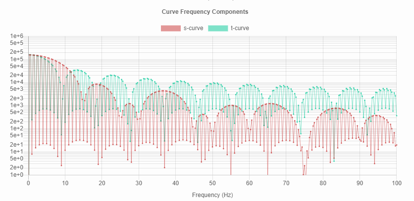
With these settings, the trapezoidal curve will be smoother for a system with a resonant frequency of 10Hz, and the s-curve will be smoother for resonant frequencies of 16Hz.
That means curves can be tuned to give ideal response for a system with a single resonant frequency (which is the case in all the videos linked above). These points of resonance are dependent on maximum velocity, which is also dependent on the length of a given move (especially in 3d-printers, where short move velocity is limited by acceleration). A fair comparison would include varying maximum velocities (or varying travel lengths).
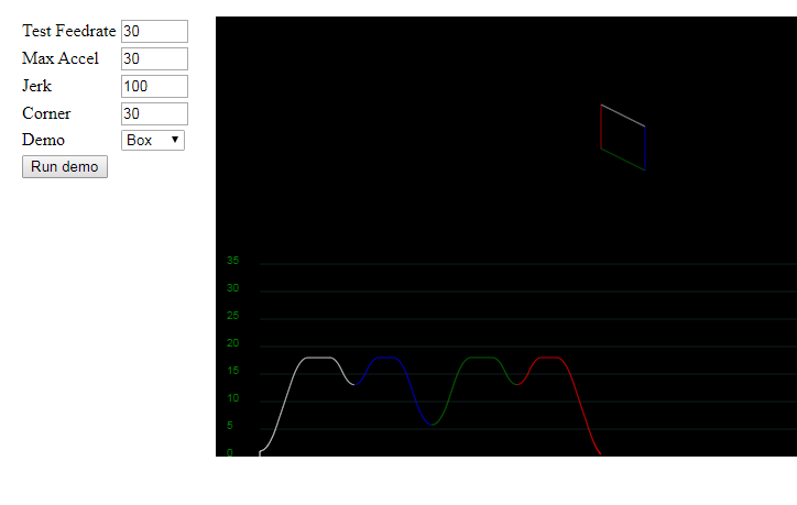
I've written an analysis tool for curve comparisons here. The values reflect real-world quantities: you can even adjust the settings to match your printer and view the excitation due to the motion profile. If you somehow know the resonant frequencies of your printer, you could even create a profile which minimized those excitations :).
So summarizing up to this point, Marlin firmware produces non-ideal artifacts in the 8-bit AVR implementation of s-curve profiles. There are probably similar artifacts in the 32 bit version, but smaller because the computation uses higher precision math (I haven't tested on a 32 bit controller... yet...). @ejtagle has done a great job explaining the algorithm earlier in this thread, and various comments/analysis strongly suggest that it's an issue with the precision of the current s-curve implementation. Increasing the precision would probably slow the algorithm down to the extent it causes other issues in the stepper code. Improving the precision and testing that it's sufficiently performant is a significant amount of work.
Another solution may be to re-write the algorithm completely, possibly redesigning the step loop to fire at a high constant rate (>10Khz) which would allow accurate discrete integration like @ryannining's code uses. That's also a significant amount of work.
For now, I'd suggest that anyone enabling s-curve acceleration on 8-bit devices do so with caution and a significant amount of testing. I've yet to see a case where enabling s-curve acceleration directly causes missed steps, but I'd recommend anyone debugging such issues disable s-curve acceleration first. There are benefits to s-curve acceleration, but since this bug adds spikes in velocity, it's likely that the trapezoidal curves will work better.
xenovacivus
on 27 Apr 2020
Hi,
Just wanted to add that an accelerometer could be placed on the printer,
perhaps at varying points, and a test profile of different speeds,
velocities, junction deviation, or jerk run through the printer as a gcode
in order to excite those resonant frequencies that could help in designing
an s curve profile for a specific printer. The acceleration data would have
to be read and correlated precisely with the movements though which could
possibly be done through octoprint. This kind of test would also help in
tuning junction deviation and acceleration.
I also wanted to add that I have done some testing with an SKR pro and I've
gotten the micro stepping to 1/64 without skipping steps up to 300mm/sec
and the interpolation is still on to interpolate up to 256. 1/128 is too
much for it at speeds above ~100mm/sec. Would having a faster processor
like the SKR pro allow for more advanced calculations with s curve
acceleration?
This work is awesome and very interesting good job guys!
DroneMang
On Sun, Apr 26, 2020, 8:38 PM xenovacivus notifications@github.com wrote:
Hi, thanks for the continued interest in this issue :)
Are we chasing s-curve profiles because of benefits claimed in articles
https://github.com/synthetos/TinyG/wiki/Jerk-Controlled-Motion-Explained
and youtube videos https://www.youtube.com/watch?v=PGYBqAphBHw aimed to
market https://www.youtube.com/watch?v=C0XjXqO6Ji8, sometimes with obviously
mismatched comparisons https://www.youtube.com/watch?v=qYJpl7SNoww? Is
the perceived benefit of s-curve acceleration just a placebo effect?What I've found is that s-curve profiles are generally better - but not
universally. For a system with a given resonant frequency, it's possible to
design an s-curve profile that produces lower vibration than a trapezoidal
profile and vice versa. For example, this graph shows the frequency
components of an s-curve and its equivalent trapezoidal curve:
[image: image]
https://user-images.githubusercontent.com/2166982/80322487-72fc9e80-87da-11ea-95e5-992cc19608a3.pngWith these settings, the trapezoidal curve will be smoother for a system
with a resonant frequency of 10Hz, and the s-curve will be smoother for
resonant frequencies of 16Hz.That means curves can be tuned to give ideal response for a system with a
single resonant frequency (which is the case in all the videos linked
above). These points of resonance are dependent on maximum velocity, which
is also dependent on the length of a given move (especially in 3d-printers,
where short move velocity is limited by acceleration). A fair comparison
would include varying maximum velocities (or varying travel lengths).I've written an analysis tool for curve comparisons here
https://xenovacivus.github.io/s-vs-t-curve/s-vs-t-curve.html. The
values reflect real-world quantities: you can even adjust the settings to
match your printer and view the excitation due to the motion profile. If
you somehow know the resonant frequencies of your printer, you could even
create a profile which minimized those excitations :).So summarizing up to this point, Marlin firmware produces non-ideal
artifacts in the 8-bit AVR implementation of s-curve profiles. There are
probably similar artifacts in the 32 bit version, but smaller because the
computation uses higher precision math (I haven't tested on a 32 bit
controller... yet...). @ejtagle https://github.com/ejtagle has done a
great job explaining the algorithm earlier in this thread, and various
comments/analysis strongly suggest that it's an issue with the precision of
the current s-curve implementation. Increasing the precision would probably
slow the algorithm down to the extent it causes other issues in the stepper
code. Improving the precision and testing that it's sufficiently performant
is a significant amount of work.Another solution may be to re-write the algorithm completely, possibly
redesigning the step loop to fire at a high constant rate (>10Khz) which
would allow accurate discrete integration like @ryannining
https://github.com/ryannining's code uses. That's also a significant
amount of work.For now, I'd suggest that anyone enabling s-curve acceleration on 8-bit
devices do so with caution and a significant amount of testing. I've yet to
see a case where enabling s-curve acceleration directly causes missed
steps, but I'd recommend anyone debugging such issues disable s-curve
acceleration first. There are benefits to s-curve acceleration, but since
this bug adds spikes in velocity, it's likely that the trapezoidal
curves will work better.—
You are receiving this because you were mentioned.
Reply to this email directly, view it on GitHub
https://github.com/MarlinFirmware/Marlin/issues/12491#issuecomment-619651248,
or unsubscribe
https://github.com/notifications/unsubscribe-auth/AIZZJSC4RCVU5ZOX7A7RCZ3ROTHYPANCNFSM4GFKYYSQ
.
DroneMang
on 27 Apr 2020
There is a big discussion on the issues and proper implementation of S-Curve ongoing in Klipper as well: https://github.com/KevinOConnor/klipper/issues/57
Very interesting read, especially in the lower third of the thread.
 Sineos
on 27 Apr 2020
Sineos
on 27 Apr 2020
@xenovacivus is the issue still there?
boelle
on 21 Jun 2020
Lack of Activity
This issue is being closed due to lack of activity. If you have solved the
issue, please let us know how you solved it. If you haven't, please tell us
what else you've tried in the meantime, and possibly this issue will be
reopened.
boelle
on 23 Jun 2020
This issue has been automatically locked since there has not been any recent activity after it was closed. Please open a new issue for related bugs.
![github-actions[bot] picture](https://avatars2.githubusercontent.com/in/15368?v=4&s=40) github-actions[bot]
on 23 Aug 2020
github-actions[bot]
on 23 Aug 2020
Related issues
 Anion-anion
·
3Comments
Anion-anion
·
3Comments
 ShadowOfTheDamn
·
3Comments
ShadowOfTheDamn
·
3Comments
 esenapaj
·
3Comments
esenapaj
·
3Comments
 otisczech
·
3Comments
otisczech
·
3Comments
 manianac
·
4Comments
manianac
·
4Comments
Most helpful comment
I find it sad that issues with that level of quality input seem to beclosed without any solution.