Marlin: Allow Zero Extruders, revisited from #10212 -> E0 direction problem
Description
This is a clarification-sort-of request over issue #10212 regarding the resultant improper behavior of E0 on a Ramps 1.4 board, where the motor will always turn in association with X, but only towards one direction.
This and the original issue deal with the use (or misuse perhaps) of Marlin firmware with a "pure CNC" machine (without extruders) where there are two stepper motors for each of the X and Y axis and one for the Z axis (or possibly other combinations), which allows a simple solution for using all five driver boards. The alternative would be to wire two motors (in series) on each of the X and Y drivers, which may be messy and is prone to destructive mistakes. This setup is the most obvious one for an MPCNC (mostly printed CNC).
_- Clarification request: how is this E0 direction problem fixed?_
Steps to Reproduce
- The steps needed to reproduce the issue:
- just follow the steps in issue #10212 .
Expected behavior:
- software X linked to hardware X and E0 (in opposing directions);
- software Y linked to hardware Y and E1 (in opposing directions);
- software Z linked to hardware Z.
Actual behavior: (in differences from the expected)
- software X is improperly reflected by E0: the movement exists but always towards a given direction.
Additional Information
- the DIR pin on the E0 driver board is always at a high (5VDC) state;
- this issue is described by @Maglin in https://github.com/MarlinFirmware/Marlin/issues/10212#issuecomment-375984428
- a solution was provided by @Bob-the-Kuhn https://github.com/MarlinFirmware/Marlin/issues/10212#issuecomment-375991203 but the Dropbox link is currently dead (404).
 bowzee
All 17 comments
If you want to use X_DUAL_STEPPER_DRIVERS and Y_DUAL_STEPPER_DRIVERS with an extruder, the correct order to connect your stepper motors to the board is: X, Y, Z, E0, X2, Y2.
 thinkyhead
on 29 Sep 2018
thinkyhead
on 29 Sep 2018
As far as I understand, bowzee doesn't need/want an extruder, but wants to use the 5 steppers on a RAMPS board as X, Y, Z, X2 (E0), Y2(E1). Apparently, it works apart from X2/E0 which only rotates in one way.
 TheSFReader
on 29 Sep 2018
TheSFReader
on 29 Sep 2018
I know this is a hardware change for a software issue, but couldn't you rewire x and x2 to rotate in opposite directions from the same port/driver, do the same with y, and have 2 free stepper drivers to use for an e?
 Phr3d13
on 29 Sep 2018
Phr3d13
on 29 Sep 2018
bowzee doesn't need/want an extruder, but wants to use the 5 steppers on a RAMPS board as X, Y, Z, X2 (E0), Y2(E1)
Well, at the moment Marlin can't support 0 extruders, so if there are only 5 stepper drivers, then the E pins need to be cleverly re-mapped in the pins_MYBOARD.h file so that X2 gets mapped the first E driver and Y2 gets mapped to the second E driver. This is easy enough. The E1 pins should be set to the current E0 pins, the E2 pins should be set to the current E1 pins, and the E0 pins should be set to the current E2 pins (which are presumably fictional). The pins.h file will then do the auto-mapping of X2, Y2 to the first and second drivers.
thinkyhead
on 29 Sep 2018
@TheSFReader, yes: X, E0=X2, Y, E1=Y2, Z and no extruders
@Phr3d13, yes that is possible but I already blew up 8 driver boards in the process, they seem to catch fire (literally) in a cascade LOL.. That is one of the main reasons for separating everything nicely.
@thinkyhead, yes, I am aware that Marlin is meant for 3D printers, with an extruder, that is why I employed the term "misuse" in my description. But issue #10212 deals/solves this. I will look into your suggestion regarding pins_MYBOARD.h, although it seems to be a hard task and I am really afraid of breaking something (hardware / software) in the process.
bowzee
on 29 Sep 2018
it seems to be a hard task
It's not too hard. Here's an example:
Before:
// E0 plug
#define E0_STEP_PIN        28
#define E0_DIR_PIN         27
#define E0_ENABLE_PIN      29

// E1 plug
#define E1_STEP_PIN        25
#define E1_DIR_PIN         24
#define E1_ENABLE_PIN      26
After:
// (fake pins for E0)
#define E0_STEP_PIN        60
#define E0_DIR_PIN         60
#define E0_ENABLE_PIN      60

// E0 plug (auto-mapped to X2)
#define E1_STEP_PIN        28
#define E1_DIR_PIN         27
#define E1_ENABLE_PIN      29

// E1 plug (auto-mapped to Y2)
#define E2_STEP_PIN        25
#define E2_DIR_PIN         24
#define E2_ENABLE_PIN      26
@thinkyhead, OK thanks! I will give it a try and post the results. The machine currently looks like this:

(some parts have not been printed yet)
bowzee
on 1 Oct 2018
Cool looking machine.
thinkyhead
on 3 Oct 2018
@thinkyhead
Cool looking machine.
Thanks!
I tested your solution and it is almost working. The motor connected to E0 (which is E1 in the software) now rotates in the correct directions, but it still does not replicate X exactly: while X moves smoothly, E0 will hop many steps at a time, while (interestingly) maintaining the same total distance. This does not happen with E1 (E2 in software). I suppose it is some parameter I missed.
Do you have any further suggestions?
This is the modified part of pins_RAMPS.h :
#define E0_STEP_PIN        57 // dummy MPCNC
#define E0_DIR_PIN         57 // dummy MPCNC
#define E0_ENABLE_PIN      57 // dummy MPCNC
#ifndef E0_CS_PIN
  #define E0_CS_PIN        57 // dummy MPCNC
#endif

#define E1_STEP_PIN        26 // X2 MPCNC
#define E1_DIR_PIN         28 // X2 MPCNC
#define E1_ENABLE_PIN      24 // X2 MPCNC
#ifndef E1_CS_PIN
  #define E1_CS_PIN        42 // X2 MPCNC
#endif

#define E2_STEP_PIN        36 // Y2 MPCNC
#define E2_DIR_PIN         34 // Y2 MPCNC
#define E2_ENABLE_PIN      30 // Y2 MPCNC
#ifndef E2_CS_PIN
  #define E2_CS_PIN        44 // Y2 MPCNC
#endif
All I can think of is to make sure your X and X2 stepper drivers are identically configured, with the same micro-step jumpers, the same current Vref, etc.
thinkyhead
on 3 Oct 2018
@thinkyhead, all of the jumpers are identically set. I suppose it must be at some point where there is a clear distinction between X and E0(hard) = E1(soft), but I would not know where to look
bowzee
on 3 Oct 2018
Just making sure
bowzee
on 4 Oct 2018
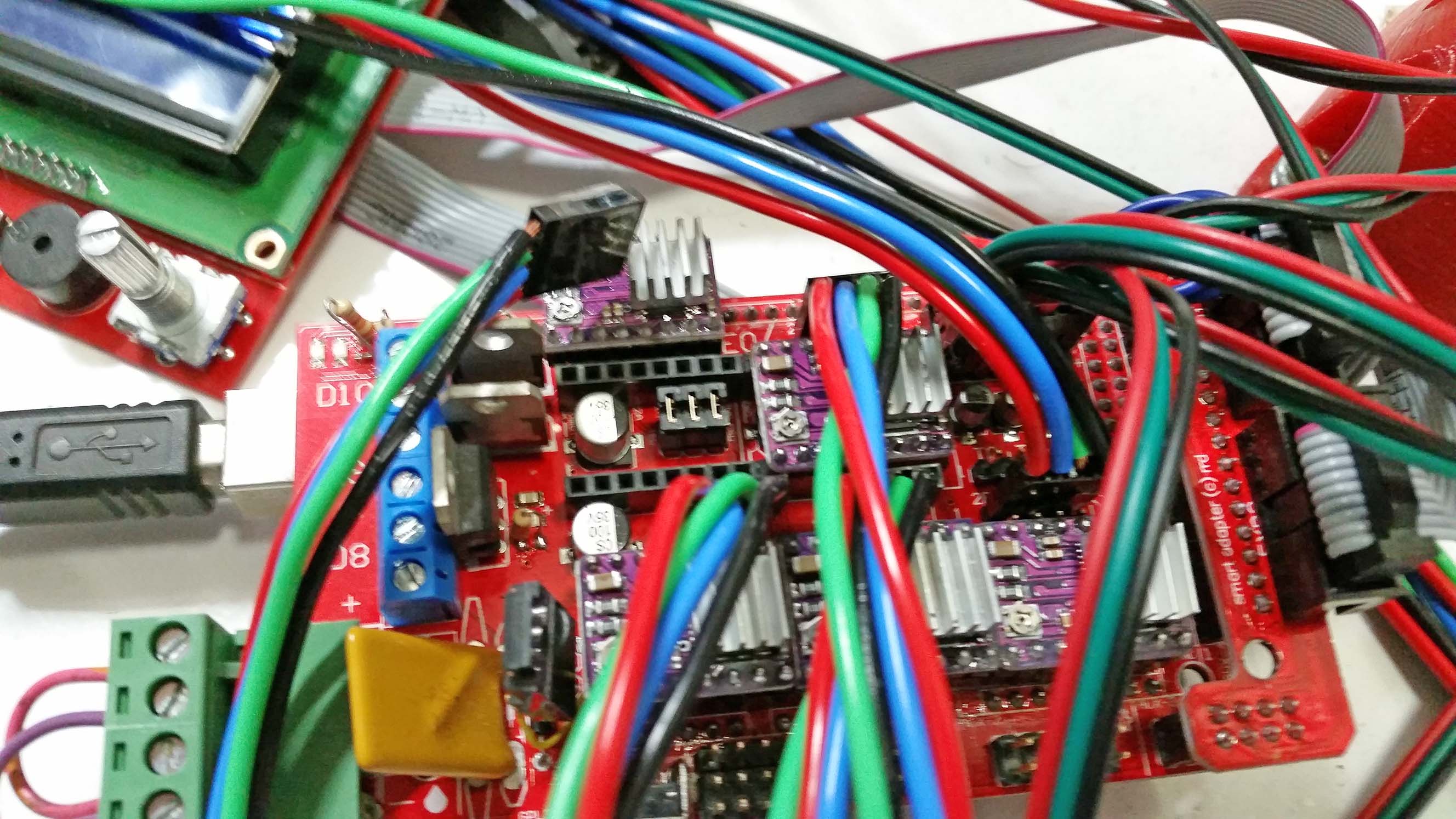
Well, I gave up trying to adjust the software, so now the machine is using 3 driver boards with 2 motors on X in series and 2 on Y as well. For anyone interested, the current adjustment on the driver board pot is the same as for a single motor and the board I used is this one (feel free to use), top view:
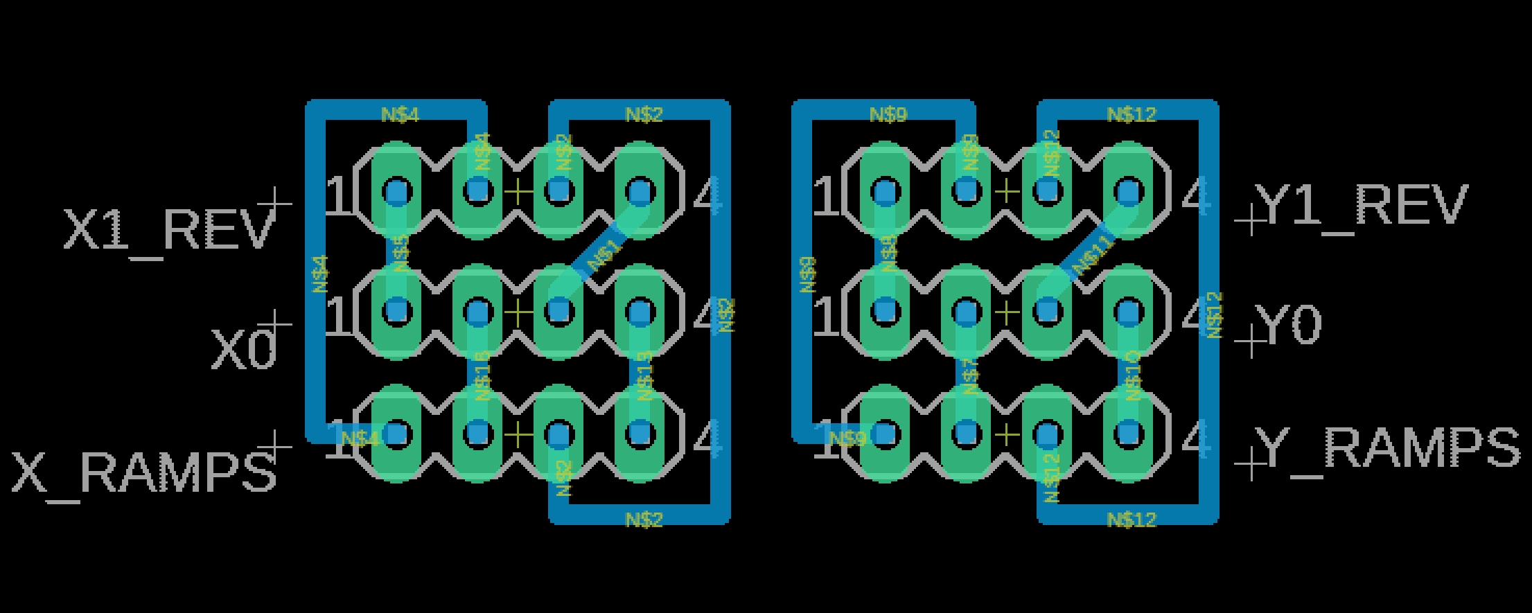
Tested and working
bowzee
on 8 Oct 2018
Bowzee, I already have pre-made firmware for the dual end stops working on the site. Maybe you can find your answer in my firmware.
 Allted
on 25 Feb 2019
Allted
on 25 Feb 2019
I also have a desire to modify Marlin to be extruder-less, also for just XYZ motion of a MPCNC cnc router.
While this pin number hack seems to be somewhat of a solution, allowing zero extruders should eliminate a lot of code from Marlin.
 bockpa
on 2 Sep 2019
bockpa
on 2 Sep 2019
Or perhaps it should be automatically extruderless when picking the "Spindle Fan" version of Marlin
#define MOTHERBOARD BOARD_RAMPS_14_SF
bockpa
on 2 Sep 2019
This issue has been automatically locked since there has not been any recent activity after it was closed. Please open a new issue for related bugs.
![github-actions[bot] picture](https://avatars2.githubusercontent.com/in/15368?v=4&s=40) github-actions[bot]
on 4 Jul 2020
github-actions[bot]
on 4 Jul 2020
Related issues
 Matts-Hub
·
3Comments
Matts-Hub
·
3Comments
 StefanBruens
·
4Comments
StefanBruens
·
4Comments
 esenapaj
·
3Comments
esenapaj
·
3Comments
 Bobsta6
·
3Comments
Bobsta6
·
3Comments
 otisczech
·
3Comments
otisczech
·
3Comments