Marlin: [FR] Prusa MMU 2.0 support
I will try to add support for the Prusa MMU 2.0 to Marlin as soon as I have a unit at hand. So just to avoid reinventing the wheel: is anybody already working on MMU 2.0 integration?
 revilor
All 370 comments
I guess Prusa will publish their sources, so we probably we should wait for that?
 brandstaetter
on 18 Sep 2018
brandstaetter
on 18 Sep 2018
Prusa already released source code of their firmware with MMU support.
https://github.com/prusa3d/Prusa-Firmware/blob/MK3/Firmware/mmu.cpp
 rmoravcik
on 18 Sep 2018
rmoravcik
on 18 Sep 2018
I walked through the Prusa sources already. Nothing too complex, but we'll have to generalize, implement the serial communication based on the HAL, etc. to make the MMU usable with as many printers as possible.
revilor
on 18 Sep 2018
So I didn't buy an MMU from Prusa I made one myself. My trouble right now os just the communication. Like I try to explain below.
The system is simple and just need messages system by Serial to work independently. Just an add-in system.
Objective:
Connect One Multi-Material unit to a printer with communication by Serial on pins Rx2Tx2 (MEGA + RAMPS 1.4 configuration)
What's needed:
Make a Clone of all movements of extruder E0 to other motor (E1) same way that we can make with the Axis like Z and Z2.
Instead of Make some tool change, pick the T number and send it by Serial on format "T1." or "T2." or "T3." , Etc. To change the tool on multi material unit.
just continue the print after receive "OK." for example.
I know, this isn't a trouble is an improve to new generations of printers with a lot of material with just one extruder noozle and with direct drive extruding with just one motor on head.
Can you help me?
If you are available to help me I'll post here all the hardware and the code of Multi Material Unit after test and check that os works well.
This was what I posted on #11879
 FNeo31
on 20 Sep 2018
FNeo31
on 20 Sep 2018
It shouldn't be too tricky to implement, except that right now we don't support a second serial connection in the AVR version of Marlin. So that would need to be added in.
Does it really need multiple extruders to be defined in Marlin and multiple sets of stepper signal pins? It was my understanding that a single E0 extruder is all that's needed from the Marlin side, and the steppers on the MMU are controlled by its onboard MCU.
 thinkyhead
on 20 Sep 2018
thinkyhead
on 20 Sep 2018
@FNeo31 is your MMU based on the PCB and firmware published by Prusa? I'm building one myself, waiting for the PCB at the moment.
From my understanding there is no replication of extruder movements to the MMU. The MMU loads the filament into the extruder and then moves out of the way. The extruder will then pull the filament just through the MMU box. Otherwise you would have to take care for some slack in the filament path should extruder and MMU get out of sync (like the Mosaic Palette+ does).
revilor
on 20 Sep 2018
Just peeked at the MALYAN_LCD which uses Serial1, and evidently we can do that on AVR very easily. So strike my previous comment about serial.
thinkyhead
on 20 Sep 2018
It shouldn't be too tricky to implement, except that right now we don't support a second serial connection in the AVR version of Marlin. So that would need to be added in.
Does it really need multiple extruders to be defined in Marlin and multiple sets of stepper signal pins? It was my understanding that a single E0 extruder is all that's needed from the Marlin side, and the steppers on the MMU are controlled by its onboard MCU.
That's also my understanding, yes.
revilor
on 20 Sep 2018
Just peeked at the
MALYAN_LCDwhich usesSerial1, and evidently we can do that on AVR very easily. So strike my previous comment about serial.
I already created PR #11880 to enable additional uarts. But I'll have a look at the MALYAN_LCD.
revilor
on 20 Sep 2018
Just peeked at the
MALYAN_LCDwhich usesSerial1, and evidently we can do that on AVR very easily. So strike my previous comment about serial.I already created PR #11880 to enable additional uarts. But I'll have a look at the MALYAN_LCD.
Ok, MALYAN_LCD uses Arduino Serial1 directly. But to provide MMU support also for boards other than AVR some abstraction in the HAL will be required, I guess.
revilor
on 20 Sep 2018
The HALs all provide some kind of emulation of the Arduino Serial# ports, so things like MALYAN_LCD ought to work with any MCU.
thinkyhead
on 20 Sep 2018
Hello, how are you ?, I'm trying to develop the adaptation for marlin I believe that the most complex part will be interpreting the gcode sent by the serial to select the filament and its respective size
 radsonpatrick
on 27 Sep 2018
radsonpatrick
on 27 Sep 2018
@radsonpatrick My MMU build is still missing the control board, so for the moment I'm using one Arduino Mega2560 + RAMPS for Marlin and another Mega2560 emulating the MMU 2 unit. This way I can implement the serial communication without an actual MMU. I have the initial setup routine (requesting version, buildnr and FINDA status from the MMU) working with my emulator. Next step will be to implement the filament load/unload commands. If you are interested I can push the current state to my github repository.
There is no gcode send to or from the MMU by the way. The printer firmware sends simple commands like "Unload filament", "Switch to filament x", "Load filament" to the MMU which answers "ok" when the command has been executed.
revilor
on 27 Sep 2018
Do you already have som documentation how you build everything? Or is it just a RAMPS +
spare Mega2560 for now?
It would be nice if you can push everything to a repository that we can have a look. I am more then willing to support 👍
 Lyr3x
on 27 Sep 2018
Lyr3x
on 27 Sep 2018
I want to understand, so he does not cut filaments in size? than a cutting blade would be serious for that, but that's more sense, would not it just interpret the M600 code?
radsonpatrick
on 28 Sep 2018
The spare Mega2560 is emulating the MMU until I have a working MMU2 unit. Connecting the real MMU2 to the printer board is quite straightforward.
But first a short disclaimer: the following info is without guarantee, it's based on the assembly guide and the schematics for the control board published on Prusa's github repository. So if you kill your MMU2 by connecting it to any printer other than the Prusa Mk3, don't blame me for that.
Ok, so to hook up the MMU to a RAMPS board you can follow https://manual.prusa3d.com/Guide/3.+Electronics+and+MMU2+unit+assembly/757?lang=en down to Step 40.
The power cable (green) will go to your power supply. Prusa uses 24V on the Mk3, but 12V should be fine for the MMU steppers, too.
The signal cable (pink) has the following connections
- +5V - blue wire
- RX - white wire
- TX - green wire
- RESET - brown wire
So on the RAMPS board you will connect
- the blue wire to a free 5V pin,
- RESET to a free digital pin,
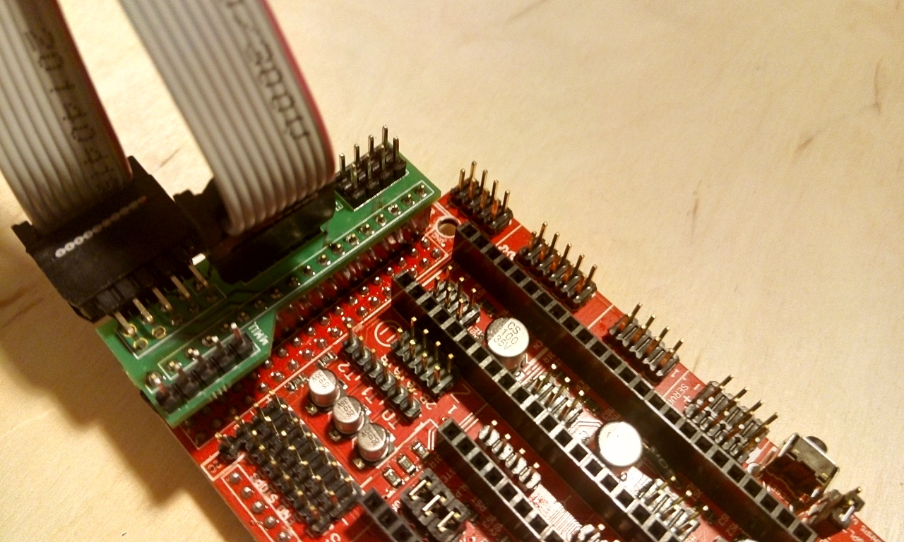
- RX (white) to pin 16 (TX2)
- TX (green) to pin 17 (RX2)
If you have an LCD connected to AUX-4, pins 16 and 17 could be an issue, depending on the display at use. But UART0 is USB, and the pins of UART1 and UART3 are used for endstops, so UART2 is the only remaining serial to communicate with the MMU2.
SoftwareSerial might be an option in case pins 16 and 17 are used for the display, or for printer boards which have no serial connection at all.
revilor
on 28 Sep 2018
I'm not using the prusa, I'm using marlin 1.1.9, so it will not be useful to me, I watched some videos and I understood the operation, so your already in what stage? charging the filament? communication with the main arduino?,I want to be a DIY
radsonpatrick
on 28 Sep 2018
I'm working in a MMU system made by me to the tool seletor on MMU and positioning I'm using a 28YBJ-48 stepper with a ULN 2003 drivers to be more compact. For the MMU board I'm using one Arduino nano with ATmega 328.
I'll Change the pin -Y to the position of X+ top put the end stop of Y and conect the serial2 of mega+ramps1.4 to the nano.
The extruder motor I will clone to feed motor on MMU. Direct controlled by main board. Instead of blade I Will put a gate stop.
PS I don't have a PRUSA too
FNeo31
on 28 Sep 2018
If you need help with something I am at your disposal. Do you have photos of the project? will you use the same desing as mmu2.0?
radsonpatrick
on 28 Sep 2018
@FNeo31 @radsonpatrick I'm building a Prusa MMU2 myself based on the sources published on Prusa's github repository. If everything works out - missing part is the controller board - I'll have an exact clone of the original Prusa MMU2.
Therefore what I'm implementing in Marlin is based on the firmware and communication protocol for Prusa's MMU2. If your self-designed MMU units behave in exactly the same manner they should work, too.
revilor
on 28 Sep 2018
Is your documentation of the development of your project in github?
radsonpatrick
on 28 Sep 2018
@revilor If you need help I'm giving my whatsaap to exchange ideas about this upgrade.
radsonpatrick
on 1 Oct 2018
OT @revilor don't know if you need it or not but on aliexpress there is a mmu2 board clone available.
A question about your project, there are some parts in mmu2 that are not easily on the market (brass tubes on carriage and brass nut for ptfe come in my mind) where did you found them?
 GMagician
on 1 Oct 2018
GMagician
on 1 Oct 2018
OT @GMagician Brass tubes were no problem here in Germany, 6mm outer and 5mm inner diameter like this https://ebay.us/xATVqt Cutting to 25mm length is no problem as Brass is easy to work with. The selector is not moving too fast, so I guess reducing the openings in the printed part to 5.1mm or so and go without the brass tubes should work fine, too.
For the PTFE mount I modified the printed part using the published OpenSCAD file. I reduced the center hole to a diameter of 5mm, tapped an M6x1 thread and directly screwed in the pneumatic connector. On Twitter I have a photo https://twitter.com/revilor3d/status/1043900826257960961.
The most challenging part for me was the stepper with a 130mm shaft for the pulleys. I could not find one on the market so I modified a stepper I had laying around and replaced the shaft with a 150mm long 5mm smooth rod, photo also on twitter.
Thanks for the tip regarding the controller board. I have all the soldering equipment so doing it myself should be fine. But good to know there is a fallback should I screw up.
revilor
on 1 Oct 2018
My latest sources are now in my repository: https://github.com/revilor/Marlin/tree/MMU2
Check Configuration_adv.h and feature/Prusa_MMU2.
revilor
on 2 Oct 2018
Hello, is fully compatible MMU2 with Marlin? I'm finishing my MMU2 clone (Arduino+ramps+drv8825) , it will work with Marlin?
 makerbitter
on 8 Oct 2018
makerbitter
on 8 Oct 2018
Good question. Please try it and let us know!
thinkyhead
on 8 Oct 2018
SoftwareSerial might be an option in case pins 16 and 17 are used for the display, or for printer boards which have no serial connection at all.
Is it really possible to use two pins in software serial mode and the TMC2130 with SPI?
Connected five TMC2130 and an Full Graphics disply to my MKS Gen 1.4 so SoftwareSerial is the only option right?
Lyr3x
on 10 Oct 2018
@Lyr3x There should be ways to avoid SoftwareSerial. I assume you are not using pins 16 or 17 as CS for your TMC2130s. So the question is: what is the exact display you are using? Because most of the displays I checked do not use pins 16 and 17. In that case it would just be a question of how to get to the pins of the EXP1 connector. You could cut the wires to the display or create some kind of adapter for that purpose.
If D16 and D17 are used by the display or you can't find a way to use them, moving the Y or Z endstops to other pins could be an alternative. This would free the uart1 or uart3 pins to communicate with the MMU.
If you can't get a hardware serial to use, SoftwareSerial might be an option. But with all the timing-critical stuff that's going on inside Marlin I'm not sure it really is. The main board is asking the MMU for the FINDA status every 300ms, so there is a lot of communication. You would have to test and see if SoftwareSerial works, I guess.
revilor
on 10 Oct 2018
@makerbitter We are not there yet, but the plan is to make Marlin fully compatible with MMU2. So if your clone uses Prusa's MMU2 firmware or at least implements the MMU's serial communication protocol, it should work.
revilor
on 10 Oct 2018
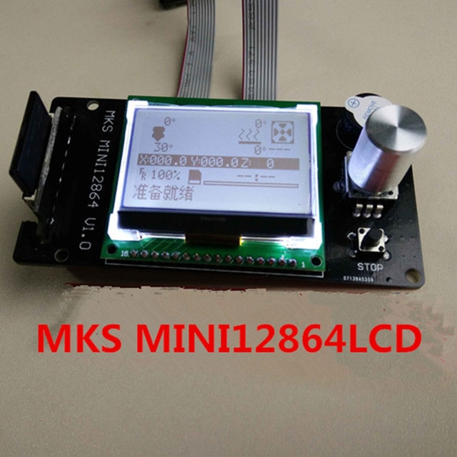
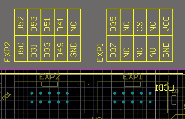
@revilor I'm using this type of Display right now: https://reprap.org/wiki/MKS_MINI_12864
Correct me if i'm wrong but it seems this type of display does not use 16/17:
#elif ENABLED(MKS_MINI_12864)   // Added in Marlin 1.1.6

      #define DOGLCD_A0         27
      #define DOGLCD_CS         25

      // GLCD features
      //#define LCD_CONTRAST   190
      // Uncomment screen orientation
      //#define LCD_SCREEN_ROT_90
      //#define LCD_SCREEN_ROT_180
      //#define LCD_SCREEN_ROT_270

      #define BEEPER_PIN        37
      // not connected to a pin
      #define LCD_BACKLIGHT_PIN 65   // backlight LED on A11/D65

      #define BTN_EN1           31
      #define BTN_EN2           33
      #define BTN_ENC           35

      #define SD_DETECT_PIN     49
      #define KILL_PIN          64
@Lyr3x From all the information I found regarding your display I would say you are good to go using pins 16 and 17 for serial. They are not used by the display.
revilor
on 12 Oct 2018
Important notice: I missread the schematics regarding the serial connection, you have to swap the green and white wire on your printer board. White is RX on the MMU side, green is TX.
So on the RAMPS board you will connect
- the blue wire to a free 5V pin,
- RESET to a free digital pin,
- RX (white) to pin 16 (TX2)
- TX (green) to pin 17 (RX2)
I corrected my comment above accordingly.
revilor
on 15 Oct 2018
Alright, everything I need is ordered. I bought the control board from AliExpress. We'll see if this is working out.
Lyr3x
on 16 Oct 2018
@revilor Do you can give an status update?
Lyr3x
on 31 Oct 2018
I plan to build my own version of MMU2 with stm32f1 board (actualy based on blue pill).
 alexxy
on 31 Oct 2018
alexxy
on 31 Oct 2018
Status update: handling filament change for the T0..4 gcode is implemented in my repository. The MMU unit seems to do what it is supposed to do for a material change. But still a lot of testing is required. My next step is to print and mount the Mk3 extruder upgrade parts and then try a real multi-material print.
revilor
on 2 Nov 2018
Btw is it possible to have 2 mmu2 units?
alexxy
on 8 Nov 2018
@alexxy To control 2 MMU units you require two free serial ports on your printer board. And support for two MMUs in Marlin, of course.
revilor
on 10 Nov 2018
@revilor
Which board do you use currently? Did you build your own MMU2?
 blackus3r
on 14 Nov 2018
blackus3r
on 14 Nov 2018
Hi there, If you are interested I ported MMU2 firmware for Ramps... It could help in Marlin part.
It is still the first implementation, I have to tweak motor movement to do not grind too much during homing (no feedback from tmc's drivers). In the following days, I should fix those issues.
My fork: https://github.com/bula87/MM-control-01
 bula87
on 15 Nov 2018
bula87
on 15 Nov 2018
I did an mmu2 implementation using Ramps board + Arduino mega 2560. It has been fully operational since October 20th, 2018. I print every day with it and added a 2nd sensor at the top of the mk3 extruder to make it extremely reliable. Code was developed from scratch. https://github.com/cskozlowski/mmu2
 cskozlowski
on 15 Nov 2018
cskozlowski
on 15 Nov 2018
Is there any progress in Marlin implementation? Is only compatible with Mk2.5/MK3 firmware?
makerbitter
on 15 Nov 2018
Check the repository from revilor. He's implementing it in a way that we can use the official Hardware. I can test it soon
Lyr3x
on 15 Nov 2018
I do not understand, why it should be so complicated.
As I understand by now, the MMU2 controller get only comandos like "retract filament into mmu2" "select tool" and "load filament into extruder". Also the MMU2 sends Back an OK. By the way - which are the exact commands transfered between both controllers?
So "communication" should be very simple without changing anything in Marlin (or any other controller firmware).
Simply use an small extra arduino (3-4$ for a Clone). Connect dir/step signals from printer stepper driver for the extruder. The Arduino simply count steps if dir is in retract direction, resetting counter if a forward step is done. If the counter exeeds a certain number, obviously the printer has not only done a retract but fully unloaded filament.
So an "unload" can be detected by the extra Arduino. If you didn't have access to dir/step, you may simply add an optical rotary encoder to your extruder motor.
So in gcode its a simple long backward movement of the extruder (Not m600 !). I think slic3r does that anyway on colour change (with an special accelleration profile to reduce blops in filament).
As the extra Arduino detects the unload, it can send the propper comand to mmu2 controller by serial connection. So filament will be retract into mmu2.
Next step: choose material number.
In gcode move extruder 1...5 mm forward. As the extruder is empty (mmu2), nothing happens - but by dir/step or optical rotary encoder the Arduino now knows that you want material 1...5 next. Arduino waits muu2 completed filament been retracted (getting "O.K.") and sends command to choose material 1...5.
Next gcode command is m600. You need to add the lenght for loading new filament, as normaly the filament would be squezed out of the nozzle to clear it, but we only have to put it to the nozzle, squezing and clearing will be done in wipe tower (or infill or extra object).
M600 will mostly wait to "O.K.-button" to be pressed. So connect an relais in parallel to the O.K.-Button. So Arduino now can "Push" O.K. when it gets the o.k. for new filament loaded from mmu2 by serial. This May not needed, if printer has filament-sensor and filament-autoload.
The difference between changing marlin and / or mmu2 firmware and using an "Interface-Arduino" is, that an Interface-Arduino would work with nearly any firmware - not only Marlin.
 OleUrgast
on 21 Nov 2018
OleUrgast
on 21 Nov 2018
@blackus3r I used the printed parts and PCB from Prusa's github repository to build a MMU2 clone.
revilor
on 24 Nov 2018
The electronics of my MMU 2.0 clone is working nearly fine, but i have some issues with filament loading (filament is slipping) and homing of the mmu. The stallguard threshold is not working fine for me.
Lyr3x
on 27 Nov 2018
@revilor your Marlin is fully functional with the MMU 2 clone board? Did you make prints successful?
makerbitter
on 27 Nov 2018
Has anyone got a functioning marlin fw for a genuine MMU 2.0 with ramps 1.4
I've enabled all the options, 5 extruders, the multiplexer, nozzle park and advanced pause feature but still need to find the pins so I can change them as I have a full graphics display and anything else I'm missing for the proper communication between the two
 0lympu5
on 7 Dec 2018
0lympu5
on 7 Dec 2018
I am also a little confused. As I see there is cskozlowski´s code to implement the MMU2 with an MEGA2560/RAMPS but this only works with the einsy board and the prusa firmware.
But is there a current way to interface it to marlin fw?
 yellobello
on 8 Dec 2018
yellobello
on 8 Dec 2018
the latest versions of marlin have all the options for it
0lympu5
on 8 Dec 2018
Where can I download?
makerbitter
on 8 Dec 2018
It's all within the latest release of marlin, but again I'm not sure if what I've by will work or if there are more options that need to be tweaked as I haven't got my mmu2 yet. Was hoping someone here could help me eventually
0lympu5
on 8 Dec 2018
I the Marlin 1.1.9 is no included. Could you send me the download link?
makerbitter
on 8 Dec 2018
Check the config file it's next to the signal nozzle and Cyclops options. It'll then make you enable nozzle park, advanced pause feature and 5 extruders. Plus which ever pins you want to set as the outputs but I used the default ones so far
0lympu5
on 8 Dec 2018
That's as much as I've done so far, knowing my luck it's more complicated than that and I'll have to modify the mmu 2 fw and potentially add more to marlin. I heard people talking about hal files and such which I don't know what they are
0lympu5
on 8 Dec 2018
@0lympu5 It for sure is more complicated than just enabling 5 extruders. The serial communication between MMU2 and the printer has to be implemented in Marlin. I'm working on that and if you are interested check my repository which also has a description of how to wire the MMU2 to a RAMPS board.
Unfortunately I'm very busy at work these days so at the moment the project is stalled on my side. The code as is should work but is not tested yet. Therefore I would not recommend using it but if you want to be the first alpha tester please let me know.
revilor
on 9 Dec 2018
@revilor the repository link don't work. I have a MMU2 board, I would like test the MMU2 with your Marlin.
makerbitter
on 9 Dec 2018
Looks like I lost a 2 in copying the URL, the repository link is fixed now.
The configuration options for MMU2 are located at the and of Configuration_adv.h
revilor
on 9 Dec 2018
obviously im just spit balling here as i ordered my mmu2 late so wont be shipped for a while. What is it like editing firmware for prusa printers, just an idea if i bought the Einsy board that is used on the mk3 and just change relevant settings like bed size, etc
0lympu5
on 9 Dec 2018
Olympu5, sorry but I have the feeling that you are mixing things up here.
MMU2 support is not built into marlin at this time. What is built in is "MK2 Single Nozzle Multi-Material Multiplexer" which is the old MMU for the MK2 printer version.
Based on your recommendation I bought the MMU2.0 and am now standing here without marlin support. Next time when you make claims, please make sure they are true.
But I should also have checked myself.
Ok, so what is left is revilor´s (UNTESTED!) code which is based on an old (3months) marlin 2.0 which I also can´t use since at this time there were problems with my LPC1768 board.
So, now I will try to move the changes to a current marlin.
yellobello
on 11 Dec 2018
Sorry for an inconvenience but i was asking a question and not stating any working prototype. I already have the hardware to potentially run a mmu, with a ramps board and cnc expansion board just the adapter is plagued with issues of switching filaments.
0lympu5
on 11 Dec 2018
@revilor Obviously the most complicated part is getting the two boards to talk to one another, I have a cnc expansion board giving me 6 extruder outputs so far. Is it possible to use this instead of the multiplexer, im presuming id need to add endstops for homing and connect the finda probe straight to the main board if a tool selector code was available.
If not im struggling with the wiring of the ramps as i have a full graphics display taking up pins 16 an 17, i only have 3 endstops so there is space there if it useful also aux 2 is empty
0lympu5
on 11 Dec 2018
@yellobello I just merged the latest 2.0 branch into my MMU2 branch. So it's no longer based on a 3 months old Marlin 2.0 - but still untested.
revilor
on 12 Dec 2018
@yellobello I just merged the latest 2.0 branch into my MMU2 branch. So it's no longer based on a 3 months old Marlin 2.0 - but still untested.
Ohnnnooooo! I just did the exact same thing last night... we should have told each other so one of us would have had less work ;-(
But, while doing this it came to my attention that the LPC1768 code uses different designations for the serial ports.. for the AVR version its "internalSerial", for LPC1768 it is "SERIAL_PORT_X" where X is one of 4 serial ports to choose from. OK, this can be easily fixed. Going further, the LPC1768 serial port code is much much simpler than the AVR code, where loads of functions like SERIAL_ERRORPGM() are not implemented... I currently I loads of compile errors with this. Let´s see where it will take me .. probably not too far since my C++ is a bit rusty
yellobello
on 12 Dec 2018
@revilor when will you be able to test it. I would love to help you out and test it but my unit wont be shipped till march
0lympu5
on 12 Dec 2018
@revilor would you mind to make a pull request to have it merged into the marlin bugfix-2.0.x branch?
So, maybe Roxy3d or someone else with experience with the HAL could take it on and actually make it work, because I tried and got stuck.
yellobello
on 12 Dec 2018
As far as i tested yet, the implementation of @revilor should work. Initializing and position change of the selector worked like charm. Because of a mechanical issue with my MMU clone i couldnt print yet.
Lyr3x
on 12 Dec 2018
@Lyr3x what setup did you use?
0lympu5
on 12 Dec 2018
@yellobello I changed all my uses of SERIAL_ERRORPGM() to SERIAL_ECHOPGM() or SERIAL_ECHOLNPGM(). And I just made another change so now my branch at least compiles for LPC1768.
Regarding a pull request: I have no plans to create a PR until at least one successful multi-material print was made using a MMU2 and a printer running Marlin. And there is still some stuff missing in the implementation like a menu to manually load one of the five materials on the MMU2 for a single-color print.
revilor
on 12 Dec 2018
For LPC1768 you will have to change
#define ENABLE_INTERNAL_SERIAL 2
#define PRUSA_MMU2_SERIAL internalSerial
in Configuration_adv.h to
// #define ENABLE_INTERNAL_SERIAL 2
#define PRUSA_MMU2_SERIAL Serial2 // or whatever serial you are using for the MMU
And the hardware reset pin of course.
revilor
on 12 Dec 2018
@0lympu5 I am using a MMU 2.0 board clone with an MKS Gen 1.4 but switching this weekend to an Einsy board and hopefully i can finally make a test print
Lyr3x
on 12 Dec 2018
@Lyr3x I'd love to bear about it, I'm running ramps atm did look at einsy but no customisation really, do like tmc 2130 tho
0lympu5
on 13 Dec 2018
@0lympu5 I am just switching to the einsy because i build another printer and needed another board. So i dont need to build an adapter for the display 👍
Lyr3x
on 13 Dec 2018
@Lyr3x yeah I will need help down the line finding a replacement for pins 16 and 17 on my ramps board as I have a full graphics display
0lympu5
on 13 Dec 2018
Saw a post on Facebook about a firmware update for the mmu 2
0lympu5
on 13 Dec 2018
Can the einsy board be connected to a full graphic lcd?
@revilor Thank you for the changes to your firmware! I really really appreciate it !
I let you know when I have it printing... need to build my MMU2 first, though ;-)
yellobello
on 15 Dec 2018
@revilor is my hero right now, cant wait for mine to turn up
0lympu5
on 15 Dec 2018
A little bit offtopic, but I thought maybe you guys know.
It´s about the extruder needed for the MMU2, I figured that no extruder besides the prusa extruder will work with the multi material upgrade.
First I thought extruder type would not really matter and I could use it with my bowden extruder, then It came to my attention that the MMU2 would not account for the huge amount of filament that sits in the bowden tube between extruder and hotend and therefore can´t be used. And even if it would, the prime tower would get enormous pretty fast.
And then finally I also figured that any extruder that needs manual handling to insert the filament would also not work. I think that about every direct drive extruder that there is, uses some kind of lever mechanism to manually expand the spring that pushes the idler bracket to the drive gear.
OK, even the prusa MK3 type extruder has this spring loaded idler bracket, but it does not rely on someone pushing a lever that will open up the space to insert a filament into the drive mechanism. The simple fact that filament is pressed into the extruder drive wheel by the MMU seems to suffice to load the filament, and finally opening up the idler when the extruder is pulling the filament in towards itself.
I can´t imagine any extruder which is currently being used that does not require someone pushing the idler when loading some filament.
Do you?
And a question that is kind of related:
Why does the MMU2 itself not serve as the extruder? It can be some kind of bowden extruder and actually has everything needed to perform this task. Or am I wrong?
regards!
yellobello
on 18 Dec 2018
You may be able to tune the bowden tube length to account for the total length
I'm making a custom mk3 extruder but you could use a bondtech one, same principle as the mk3
0lympu5
on 18 Dec 2018
I don't think that is correct. My printers are using a Titan and a bondtech extruder setup. Both are capable to load the Filament without pushing the lever to release the spring. The bondtech is working even better because of the two side grip. I tested the Filament load with my mmu and when it pushed the Filament correctly the extruder was not the problem.
The only mechanical issue I have at the moment is the idler body which sometimes is not in the correct position
Lyr3x
on 18 Dec 2018
The MMU2 only cares about the distance between the extruder and itself (which is configured in the MMU). The distance from the extruder to the hotend is handled in your gcode. So the sequence for a tool change goes like this:
- move the filament up beyond the extruder gears
- MMU2 retracts the filament the remaining distance
- MMU2 moves selector to next material
- MMU2 transports the new filament down to the extruder gears
- extruder grabs the filament and transports it all the way down to the nozzle
- purge block/infill/object
- continue print
Steps 2 to 4 are handled by the MMU when a T* gcode is sent. Let's say in your bowden setup you have a distance of 500mm from the extruder gears to the tip of the nozzle. Then the simplified gcode for a tool change to material 4 would look like
G92 E0.0
; unload 505mm to make sure filament is beyond extruder gears
G1 E-505 F1000
T3
G1 E500 F1000
G92 E0.0
; purge
The real unload gcode is more complex than that because the filament has to be moved up and down some small distances several times with the right speeds to create a filament tip which does not cause a jam when the material is loaded the next time.
That's the reason why I think Prusa went back to direct drive extruder with MMU2 because this way you have better and more direct control over the filament movement. MMU2 with a bowden setup would be kind of another MMU1, which is also why the MMU2 is not working as the printer's extruder.
So back to the question of using an MMU2 in combination with a bowden extruder. I think it is possible and if tuned correctly should be at least as reliable as the MMU1, probably better because at least the problems caused by the Y-splitter are gone this way.
But finding the perfect unload gcode sequence will be some work. This also applies to any other non-Prusa printer even with direct drive extruder, by the way. You will have to find the perfect unload gcode sequence for your extruder/hotend combination. The sequence Prusa uses for the MK3 can be a starting point but you will have to tune it for your very setup. I'm sorry guys, but there is no plug and play in this.
revilor
on 18 Dec 2018
Is there any special code required for the extruder in marlin or is It all done with gcode
0lympu5
on 18 Dec 2018
Communication with the MMU is handled by the T* commands, so in the end it's all just regular gcode. You can check the examples from the MMU2 drivers package or slice a multi-material object in Slic3r Prusa Edition to see how the gcode for MMU2 prints looks like.
revilor
on 19 Dec 2018
Even though I had some misconceptions in my thoughts above, It will be clear to anyone that using a bowden extruder with the mmu2 would be quite wasteful since one would need to get rid of a lot of filament in the prime tower.
Or can you change the filament already to another color but still continue to print with the color in the bowden tube at the actual object until it is let´s say 90% empty and then go for the prime object/tower/infill ? This would need some further optimization of the gcode though.
Either way, I was afraid that only the MK3 B7 extruder would grab the filament without manual intervention so I am going to build the MK3 extruder together with my MMU2 and have the problems of matching the right combination of factors out of the way. I wanted a direct extruder back anyways, so this is my chance now.
I already designed a holder plate for the CR10, if anyone is interested.
yellobello
on 21 Dec 2018
I'm doing the same, full mk3 extruder, want to try out the laser filament sensor too. The only difference with mine is I'm running volcano but already got a modified fan blower from thingiverse.
I think the best option for purging is into another object, as about half of my printed parts are either functional or painted I get lists of 'free' models. Closely followed by wiping into infill.
0lympu5
on 21 Dec 2018
Even though I had some misconceptions in my thoughts above, It will be clear to anyone that using a bowden extruder with the mmu2 would be quite wasteful since one would need to get rid of a lot of filament in the prime tower.
Sorry to interfere here, but you still have some misconceptions: the prime tower is only necessary for the molten filament inside the hotend; the wipe amount is not influenced whether it's a bowden or direct extruder.
Only difference is that you move more filament back and forth during the swaps, but you waste not more.
brandstaetter
on 21 Dec 2018
From my understanding your only waste filament would be what ever is left between the extruder and the hot end, however I'm not sure how the mmu would handle this and depending on if or where you used a filament run out sensor, the unit could theoretically push more filament down but you would loose retraction capabilities for a little bit
0lympu5
on 21 Dec 2018
What you need to run the MMU2 with any extruder:
- an extruder where you can connect a bowden coupling to the inlet for the feeder tube
- an extruder which can reliably grab the fed filament (bondtech for example)
- a lot of experimenting and playing aroudn with values to get the removed end of the filament with the perfect conical form (no thick blob that will clog inside the PTFE feeder tube or the extruder gears
- and finally a way to serially connect and talk to the unit from the main controller board
brandstaetter
on 21 Dec 2018
Even though I had some misconceptions in my thoughts above, It will be clear to anyone that using a bowden extruder with the mmu2 would be quite wasteful since one would need to get rid of a lot of filament in the prime tower.
Sorry to interfere here, but you still have some misconceptions: the prime tower is only necessary for the molten filament inside the hotend; the wipe amount is not influenced whether it's a bowden or direct extruder.
Only difference is that you move more filament back and forth during the swaps, but you waste not more.
Now I got it.. off course, the whole filament is being pulled back.
I had the knife blade in mind and thought the whole filament would be cut off and left in the tube or something like that. It´s just the tip that is being cut off when the whole filament is pulled back.
Thank you!
yellobello
on 22 Dec 2018
Is the tip always being cut off by the MMU?
If so, why then the above mentioned procedure to shape the tip when pulling it out of the hotend.
I have a feeling that I am still somewhat wrong :-)
I don´t have the device yet and I have never seen one in action ...
yellobello
on 22 Dec 2018
No, the tip is not always cut.
I think it's currently never cut. At least for me, the MMU2 unit mostly panics (i.e. print pauses and asks for user help to remove the jam/clog) whenever something is wrong.
Yesterday one of the colors did not feed properly and caused a print failure. But that was on the 1.0.2 MMU firmware, today I updated to 1.0.3....
Currently it's very stupid and lacks some of the advertised features (like: detecting that the extruder is not feeding properly, retracting and cutting to remove the clogged tip...)
brandstaetter
on 22 Dec 2018
Any news? I am still waiting for my parts to arrive... they are now starting to come in.. almost part by part!
I just read a thread in the german reprap forum by someone who already built his own MMU2.
He made some very important points, mainly that the 8mm steel ball is actually 7,98mm and so a 8mm ball will get stuck, that only 6,2mm pulleys do work, that one should use FESTO pushfits right from the beginning, that one should print some revised STL files that he posted and when printing the MMU2 one should use 30-50% infill (Honeycomb 3D), use at least 4-5 perimeters and use no supports.
Just to let you guys know.
Revised parts:
-> https://www.thingiverse.com/thing:3237579
-> https://www.thingiverse.com/thing:3232438
-> https://www.thingiverse.com/thing:3237770
Merry Chistmas!
yellobello
on 26 Dec 2018
From my experience so far I would say the two most crucial parts in the build are the stepper motors for idlers and pulleys and the springs. I started with 17HS16-2004S (45Ncm) motors from stepperonline but could not get consistent results. Sometimes feeding filament would work, and the next time it would not. So today I replaced them with 17HS19-2004S1 (59Ncm) ones and now everything works perfect with 12V supply voltage and using the 12V/MK2 mode of the latest MMU2 firmware (1.0.3).
Regarding the springs I can't give you more than the dimensions of the ones I'm using: 5.5x17mm. It was a lot of try and error with different kinds of springs until I ended up with the ones at use now. It's like for a regular extruder but a little bit more difficult because of the idler drum mechanics: if the force of the springs is too high the stepper won't be able to bring the idler bearing into position, if it's too small the pulley will loose steps and you don't get consistent results.
So the current status on my side is as follows: I have a working MMU2 clone and have Marlin consistently feed filament to/retract filament from the extruder on tool changes. Next I will have to calibrate the MMU for the length of the PFTE tube, and then finally run a test print.
revilor
on 28 Dec 2018
Sounds like you are almost finished, i had a couple of vouchers so bought a genuine mmu2, cant wait to get it working, have you tested with 24v?
At the moment im running ramps 1.4 with tmc2208 so was looking at a possible upgrade, my main concern is as my set up stands the two systems would be running off of different supply voltages, im already using two psu as i have a large print bed but dont want any voltage jumping between boards as it were.
0lympu5
on 28 Dec 2018
I did not test it in detail with 24V, but considering the MMU2 runs with 24V on the MK3 I guess you will have no problem doing the same. Just take care you power the MMU steppers and the printer board from the same PSU. It won't work otherwise as there is no separate GND for the 5V circuit (which is powered from the printer board).
revilor
on 29 Dec 2018
Ah okay so I'd need to run everything off one power supply or connect the grounds in some way
0lympu5
on 29 Dec 2018
@0lympu5 not sure but with "switching" power units you can't connect gnd in common
GMagician
on 29 Dec 2018
Ah okay, currently I have a separate 24v psu for my heated bed and 12v for everything else, I believe they are switching power supply
0lympu5
on 29 Dec 2018
Ok guys, looks like we are getting somewhere :-)


I used the sample lizzard gcode from Prusa's MMU2 examples with the change of just one gcode to enable ABL. I had a jam and that's where the print ended because after fixing that reheating the nozzle triggered a thermal runaway. So there is still some work to do.
revilor
on 31 Dec 2018
@0lympu5 So far the MMU works really really well with a supply voltage of 12V. Therefore no need to go for 24V from my point of view. If your printer runs from 12V and everything is fine just keep it that way.
revilor
on 31 Dec 2018
Hapoy to see someone has made good progress. I did see on another forum a little mod to help with slight inconsistencies in the tip length and shape. They removed the two screws at the end of the mmu 2 holding the ptfe tube connector and replaced them with longer one plus a spring each side to take up the tolerance
0lympu5
on 31 Dec 2018
@revilor I've just cloned your repository and will attempt to replicate what you have done.
I have genuine MMU2, a custom built corexy printer, MKS gen L v1 (Ramps 1.4) board at 24V.
I am a very happy user of MK2S+MMU1 but don't want to mess a working machine by upgrading to MMU2.
 kursatu
on 1 Jan 2019
kursatu
on 1 Jan 2019
@revilor do you have any advice on setting a mmu2 up with ramps, im mainly worried about the 16 and 17 pins as mine are currently being used?
0lympu5
on 1 Jan 2019
@0lympu5 What display do you use? Maybe you don't have to worry about 16/17 at all.
I have an Anet 12864 LCD on my printer which uses the 16/17 pins. So I designed a small adapter for AUX4 on the RAMPS to connect the LCD and the MMU2 and moved the LCD pins from 16/17 to 25/27.
Depending on the endstops on your printer there might be an easier option then to mess with the AUX4 connector though. The ATMega2560 has two more serial ports. On the RAMPS the pins of those are used for Y and Z endstops. So if you have no more then 4 endstops you can just redefine the endstop pins and free pins 14/15 (Y endstops) or 18/19 (Z) to use with the MMU2.
So let's say you have the very common setup with X-/Y-/Z- endstops. Then you use X- and Y- as intended on the RAMPS and connect the Z- to the Y+ connector. In pins_RAMPS.h you define
define Z_MIN_PIN 15
and now have Serial1 on pins 18 (Z-) and 19 (Z+) free to use for the MMU connection.
revilor
on 2 Jan 2019
It seems so easy when it's put like that, thank you
0lympu5
on 2 Jan 2019
hello. i am also in the process of making a MMU2 clone and i was happy to find about this thread and the good work of the community. in the process of purchasing parts i found out two things you may find interesing..
1- the MKS MINI12864LCD from makerbase has the pins that were on 16/17 moved somewhere else so they are easier to use in conjunction with the UART.
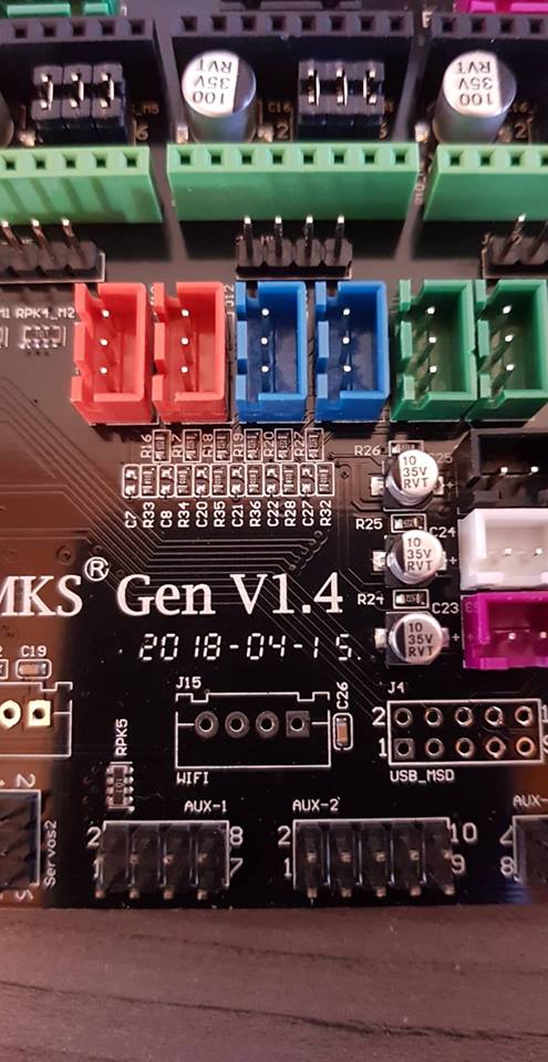
2- the board from makerbase MKS gen 1.4 has an undocumented "WIFI" connector that's ideal to connect to the MMU, i discovered this by accident after i bought it. it has a couple of solder jumpers on the back to redirect the TXD2/RXD2 to that connector
 lucassiglo21
on 2 Jan 2019
lucassiglo21
on 2 Jan 2019
Has anyone tried using the prusa laser filament sensor that sits just above the bondtech system along with the mmu or does the filament sensor in the filament selector of the mmu2 override this
0lympu5
on 2 Jan 2019
@revilor what's the messages that you sent from motherboard to MMU2?
I'm developing a different system for Multi-Material feeder, with just 2 steppers and with one Arduino nano (clone for the board).
The target is a very low cost Multi-Material feeder. The idea is be modular for future expansion, and make it easy for all to have a Multi-Material printer at home.
To don't make another brunch, just want to know the kind of messages that your brunch send from motherboard to serial1 and what's you need to reply back.
Are Serial 1 (pins 18 and 19) the preset?
I'll put all on thingiverse after test model's for print and the source code and electronics needed to build it. (Sorry for my English)
FNeo31
on 3 Jan 2019
Has anyone tried using the prusa laser filament sensor that sits just above the bondtech system along with the mmu
Unfortunately the sensor seems to be disabled in the current official firmware. I don’t know why because I imagine a lot of nice features like auto Bowden length calibration etc. Probably work in progress at Prusa research at the moment. I hope so at least
brandstaetter
on 3 Jan 2019
@FNeo31 I added a short document to my repository: serial-protocol.md. For more details you can also check the MMU2 Firmware sources on Prusa's github.
revilor
on 3 Jan 2019
Regarding the Mk3 filament sensor: I have one from the MK2.5 upgrade kit and it would be nice to make some use of it. Especially in combination with the MMU2 it would add a lot of reliability if there were feedback wether the filament reached the extruder or not.
Prusa added a Filament sensor 2.0 engine to the 3.4 release of their Mk3 firmware and they claim that some of the problems of the first iteration were ironed out. Maybe when I've finished MMU2 support it could be my next project to port this stuff over to Marlin. But it has to be reliable, otherwise it's not worth the effort. I haven't checked so far how the experiences from Mk3 users are with the new sensor engine.
revilor
on 3 Jan 2019
Yeah it seemed like a good idea, I have a rather large printer to which I added a interchangeable x carriage head, so I designed a mount for the latest prusa mk3 r3 extruder as I liked the bondtech system and looked solid for constant filament changes.
As people have said with a system such as this every way we can get the printer to check itself after tool changes is better
0lympu5
on 3 Jan 2019
@FNeo31 which stepper did you remove compared to the prusa design, I have seen a couple of prototypes that have the selector and bearings in one to remove the idler stepper. Although the tests haven't been great for the bearing is applying constant pressure, even on tool changes.
0lympu5
on 3 Jan 2019
@Olympu5 it's the CAM stepper,
place the bearing with a lever system for idler and direct connection between feeder motor and the extruder.
FNeo31
on 3 Jan 2019
Anyone looked at using the 're arm board for ramps instead of the arduino mega ?
0lympu5
on 6 Jan 2019
@FNeo31 @radsonpatrick I'm building a Prusa MMU2 myself based on the sources published on Prusa's github repository. If everything works out - missing part is the controller board - I'll have an exact clone of the original Prusa MMU2.
Therefore what I'm implementing in Marlin is based on the firmware and communication protocol for Prusa's MMU2. If your self-designed MMU units behave in exactly the same manner they should work, too.
So if I have an MMU clone or if I just bought the whole kit and connected it to my makerbase board it should work?
 xddarko
on 7 Jan 2019
xddarko
on 7 Jan 2019
I'm trying to get it to work on a MKS base, for the moment the communication is impossible !
I used part of the @revilor code on marlin 1.1.x, But I can't use the serial3 or serial4 ports
I did a test with the function "SoftwareSerial mmuSerial(15,14);"
I can transmit frames (TX) to a USB UART, the MMU do not move
Marlin is waiting for a "start", but i never get into the function "mmuSerial.available()"
Someone can look at my code ? (https://github.com/AlfiQue/MakerFr_I3-RS/tree/master/Marlin)
 AlfiQue
on 7 Jan 2019
AlfiQue
on 7 Jan 2019
I hate fw, no good at it, port rev configs into marlin 1.1x and it wont compile for my board and then try bugfix 1.1 and get stupid binary errors
0lympu5
on 7 Jan 2019
Short status update: I'm in the middle of cleaning up my stuff and make everything PR-ready. So don't mess with 1.1.x! Go for Marlin 2.0 and get ready to have the same fun with missing layers and stuff all the other MMU2-users with their Prusa printers are having already :-)

revilor
on 8 Jan 2019
I'm trying to get it to work on a MKS base, for the moment the communication is impossible !
I used part of the @revilor code on marlin 1.1.x, But I can't use the serial3 or serial4 ports
@AlfiQue I also have MKS base v 1.5 (but still waiting for my MMU2 board)! What is the problem of using pins 14+15 (serial3) to communicate? Moving x/y max/min plugs to another pins looks possible.
 Olegas
on 8 Jan 2019
Olegas
on 8 Jan 2019
FYI, I incorporated the MMU2 into my HyperCube CoreXY using a Einsy board a few days ago and I am willing to test firmware developed. I discovered this post yesterday so I will be looking to download @revilor code for testing. (Revised-- Noticed this code is for ARM processors. My board does not support this level of code.)
Two issues I have are the MMU2 unit communicating fully to allow for multi-material printing and successful activation and performance of the filament sensor.
The Prusa sensor used VCC, GND, SCL, and SDA. I have everything pinned out correctly on P3 of the Einsy board but the SDA is not in the present Marlin code and frankly I'm unclear how to embedded it or how this sensor truly works. Appreciate if someone could provide clarity and whether this has been rolled up into the Marlin 1.1.9 code for testing.
 dcwalmsley
on 8 Jan 2019
dcwalmsley
on 8 Jan 2019
@dcwalmsley Don't be misstaken. Yes, the main goal of Marlin 2.0 is support for 32bit boards but the 8bit AVR code is still there. In fact I use an Arduino Mega2560 + RAMPS 1.6 + TMC2130s in SPI mode for my printer, so I kind of have an Einsy board too :-) MMU2 works fine with Marlin in my setup so it should also be fine with the real EInsy.
Regarding the filament sensor: we don't have support for it in Marlin at the moment. It would be of great use in combination with the MMU, though. Therefore I have plans to check if the relevant code can be ported over from Prusa's firmware as soon as I'm done with the MMU2.
revilor
on 8 Jan 2019
I'm trying to get it to work on a MKS base, for the moment the communication is impossible !
I used part of the @revilor code on marlin 1.1.x, But I can't use the serial3 or serial4 ports@AlfiQue I also have MKS base v 1.5 (but still waiting for my MMU2 board)! What is the problem of using pins 14+15 (serial3) to communicate? Moving x/y max/min plugs to another pins looks possible.
I did the test will all ports, marlin does not allow the connection
AlfiQue
on 8 Jan 2019
Hi All,
Qucik status update on my integration, working towards running code.
I've pulled tthe @revilor 's fork last weekend on top of marlin2 and
started to run it on Mks Gen L V1 board on a CoreXY printer V-King.
I've assembled the original MMU2 unit.
Marlin resets the MMU2 and wait for "start" from MMU2 but i never receives it.
I've verified that Marlin can actually send and receive the data via Serial3 to an Arduino
that simulates MMU2.
I am hoping that I am close to getting it at least to control MMU2.
I still need to do a lot of work to convert the current extruder on the printer
to be something like Prusa.
kursatu
on 8 Jan 2019
@revilor I tried it with your code (in marlin 2.0), and the MMU has come to life :smiley:
Now the next step is to calibrate the MMU :stuck_out_tongue_winking_eye:
At least already a big thank to you @revilor for the work performed :wink:
AlfiQue
on 8 Jan 2019
Hi All,
Qucik status update on my integration, working towards running code.
I've pulled tthe @revilor 's fork last weekend on top of marlin2 and
started to run it on Mks Gen L V1 board on a CoreXY printer V-King.
I've assembled the original MMU2 unit.
Marlin resets the MMU2 and wait for "start" from MMU2 but i never receives it.
I've verified that Marlin can actually send and receive the data via Serial3 to an Arduino
that simulates MMU2.
I am hoping that I am close to getting it at least to control MMU2.
I still need to do a lot of work to convert the current extruder on the printer
to be something like Prusa.
The MMU turn ON ? I had a problem with my chinese board, the ground pin on the connector was not connected (I soldered it beyond that)
Do you have check that you have the TX from printer on the RX from the MMU ?
AlfiQue
on 8 Jan 2019
@AlfiQue I downloaded files for Prusa's new mk3 R3 extruder and found a version opf one of the parts on everything that was prusa sensor for a bltouch, printed everything and bought the bondtech gears from ali express
0lympu5
on 8 Jan 2019
I did the test will all ports, marlin does not allow the connection
@AlfiQue I just compiled Marlin 1.1.9 with Y_MIN pin remapped to X_MAX pin. So, I got pins 14 and 15 (previously used for Y_MIN and Y_MAX) unused. I can now use Serial3.
I've added Serial3.begin(9600) to setup() in Marlin_main.cpp and, just for check thing working fine, added sending "+" or "-" to Serial3 when encoder is rotated.
After that, I can connect to this serial with USB TTL adapter and see + and - appearing in terminal while I rotate the encoder.
Olegas
on 8 Jan 2019
I did the test will all ports, marlin does not allow the connection
@AlfiQue I just compiled Marlin 1.1.9 with Y_MIN pin remapped to X_MAX pin. So, I got pins 14 and 15 (previously used for Y_MIN and Y_MAX) unused. I can now use Serial3.
I've added
Serial3.begin(9600)tosetup()in Marlin_main.cpp and, just for check thing working fine, added sending "+" or "-" toSerial3when encoder is rotated.After that, I can connect to this serial with USB TTL adapter and see + and - appearing in terminal while I rotate the encoder.
I've already done this test, i have a compilation error : '_Serial3' was not declared in this scope_
What is your board ?
AlfiQue
on 8 Jan 2019
@AlfiQue I've got the same issue. I dig a little bit to the Marlin sources and have found what Marlin is preventing including of Arduino HardwareSerial.h, but for Maylan LCD support Marlin needs to use serial port and in malyanlcd.cpp I've found this:
#if USE_MARLINSERIAL
  // Make an exception to use HardwareSerial too
  #undef HardwareSerial_h
  #include <HardwareSerial.h>
  #define USB_STATUS true
#else
  #define USB_STATUS Serial
#endif
So, I've just put this undef-and-include stuff to the places where I need to use Serial3.
Olegas
on 8 Jan 2019
@AlfiQue I've got the same issue. I dig a little bit to the Marlin sources and have found what Marlin is preventing including of Arduino
HardwareSerial.h, but for Maylan LCD support Marlin needs to use serial port and inmalyanlcd.cppI've found this:#if USE_MARLINSERIAL // Make an exception to use HardwareSerial too #undef HardwareSerial_h #include <HardwareSerial.h> #define USB_STATUS true #else #define USB_STATUS Serial #endifSo, I've just put this undef-and-include stuff to the places where I need to use Serial3.
Thanks you for the explanation, I'll do the test
AlfiQue
on 8 Jan 2019
@AlfiQue I downloaded files for Prusa's new mk3 R3 extruder and found a version opf one of the parts on everything that was prusa sensor for a bltouch, printed everything and bought the bondtech gears from ali express
I created a piece to fit on my current head, but I will certainly do the same step as you
AlfiQue
on 8 Jan 2019
@AlfiQue thanks, it was some connection problem. The board and MMU2 communicates now but the
I see start , S1, S2 etc appearing on the pronterface console, using the latest code on the fork.
But none of the steppers rotate,they don't do the homing. The board has power. I've checked it using a multimeter at the fuse by looking at the board schema. It is a genuine Prusa MMU2 powered by 24V.
All powered by the same PSU.
Any ideas?
Thanks
kursatu
on 10 Jan 2019
@revilor,
Glad to know that the Marlin 2.0 could work on my Einsy board. Since the version 2.0 is laid out differently than the latest Marlin 1.1.9 files and folders, Would I need to copy all of Marlin 2.0 bugfix then rearrange them the same as Marlin 1.1.9 files are structured before compiling?
As for the filament sensor, I'm in no hurry for it to be implemented although I think we need a working version the supports SCL and SDA connections.
dcwalmsley
on 10 Jan 2019
@kursatu The MMU does not home on power up. That behavior changed with the latest firmware versions.
The idler drum should move on power up and also after reset, though. The selector will home when the first tool change happens. When you press the middle button on the MMU to load the first filament homing should happen.
@dcwalmsley You take a copy of Marlin 2.0 in the folder structure it is, edit Configuration.h and Configuration_adv.h, and build it just like the 1.1.* branch. Just make sure you have Ardiuno IDE 1.8.* installed.
revilor
on 10 Jan 2019
So I modified three files to fit my printer design, Configuration.h, Configuration_Adv.h, and pins_EINSY_RAMBO.h.
Compile was successful up and to the end point where I received this message, "fork/exec C:\Users\dcwal\AppData\Local\Arduino15\packages\arduinotools\avr-gcc\5.4.0-atmel3.6.1-arduino2/bin/avr-gcc.exe: The filename or extension is too long.
Error compiling for board Arduino/Genuino Mega or Mega 2560."
Any suggestions on how to get around this problem?
dcwalmsley
on 11 Jan 2019
 AnHardt
on 11 Jan 2019
AnHardt
on 11 Jan 2019
Problem resolved. Uninstalled Arduino and installed 1.8.8 into root drive of C. Then I moved any libraries and other data file to Arduino except for Sketchbook. Left that in C:temp folder. So these changes worked and I was able to compile and upload the firmware to my Einsy board.
On a side note. As of this writing, I'm not either understanding the MMU menu commands as "Loading to Extruder" doesn't seem to work, or the code is in early stage and it isn't incorporated yet. None-the-less, I'm liking the progress thus far. What can I do on the end-user side to help?
dcwalmsley
on 12 Jan 2019
My latest MMU2 codebase has now fully implemented LCD menus for filament load/unload, filament runout check using the FINDA probe, T?/Tx/Tc/M403 gcodes, and MMU support in M600. The end of my todo list is getting close.
revilor
on 13 Jan 2019
Bravo my friend @revilor
0lympu5
on 13 Jan 2019
@revilor is there any additional hardware you used to adapt the mmu 2 with the ramps board? Just got a shipping notification from prusa so wanted to get a head start.
I know I would have to split the connector from the mmu2 so I can attach it to the end stops for serial and separate place for power
0lympu5
on 14 Jan 2019
@0lympu5 No aditional hardware required. As you said: you just have to find a way to connect the MMU2 serial cable.
revilor
on 15 Jan 2019
@revilor , thanks I've started to use your code , it works well. I was delayed a bit because I apparently burned the steppers somehow, had to wait for a new board.
My setup is a genuine MMU2, MKS gen-l v1 board, CoreXY printer (V-King design).
The printer & mmu2 can load filament, load to nozzle, print.
I've just got it to work did not yet try multi material prints yet, there might be still some mechanical stuff I need to do.
I've noticed M702 C gcode, unload filament. I think it is the only way to unload a filament via gcode.
The current PR does not seem to include that, not that it should. It might be nice to have that if it makes sense.
kursatu
on 21 Jan 2019
a few quick Q's:
1) will a filament sensor be required (at the extruder)? or can it work with a titan extruder? i assume the requirement would be that the titan extruder can grab the filament on its own
2) can it work on a re-arm too?
.....
?) for the clone builders like i might be would a 2nd Ramps setup be supported? maybe the 2nd board could run as an SPI slave if there are limited serial ports like the re-arm have
 boelle
on 23 Jan 2019
boelle
on 23 Jan 2019
@boelle i cannot help with the second question but from memory of previous discussions over cloned prusa extruders the mmu2 firmware overrides the filament sensor above the extruder and relays only on the FINDA sensor. Rev has mentioned possibly adding or investigating support for the laser sensor as a filament loading fail safe.
0lympu5
on 23 Jan 2019
If you need serial ports for the mmu2 communication, Rev has discussed a potential fix for people using full graphic displays, using pins 16 and 17. The idea was to move the Z min end stop to Y max, leaving Z min and Z max open for tx and rx
0lympu5
on 23 Jan 2019
i was told that the re-arm has only 1 serial port left (if any)
i found out that when i wanted to use 5 tmc2208 that all requires interupt able pins to make the softserial for each driver work
boelle
on 23 Jan 2019
Ah i see, that solution was based on a ramps and arduino mega
0lympu5
on 23 Jan 2019
yep.... Ramps and Re-arm is a bit different :-) but i'm not going back to mega.... way to slow :-P
boelle
on 23 Jan 2019
It would seem odd that they would remove features like uart and serial pins, as they are used for more advanced control which is what re arm is all about
0lympu5
on 23 Jan 2019
but if all the endstop pins are able to work as serial pins even on the re-arm then i should be good as i only use 4 of them (dual z endstops and dual z drivers)
the thing would be that i will do a clone build as i'm limited in fonds
boelle
on 23 Jan 2019
they have not removed it on the re-arm board, i just think its more limited than an mega
and the 2 are made with different chips and from different companies
re-arm is 32 bit and the mega is only 8 bit... and one runs at 100mhz and the other at 16 mhz
boelle
on 23 Jan 2019
If you dont mind you stepper motor skipping maybe one or two steppers
when you first turn your printer on, you can use two end stops in series for z, i have done it on my build for a dual y axis, but will depend on your printer type and frame design
0lympu5
on 23 Jan 2019
Mendel90 frame, but with Mk42 clone from spain and the prusa X axis system (rotated 180 degree on y axis to have x motor on right side). and titan extruder on x carraige
i use slic3r PE and i slice as if my printer was an mk2.5, so not sure if it would work with marlin2.0
but lets see what happens, a clone build of the mmu2 with a cheap ramps board would most likely be my choice to keep the price down.... also i have to think if it would make sense and i would make use of it in the long run, if not i would just add something to the printer that is a waste of money that could be used for better things
boelle
on 23 Jan 2019
@kursatu In difference to the Prusa firmware Marlin has no C argument for M702, but you can use plain M702 without any arguments to unload the filament. In the context of the MMU2 there is no other than the current extruder to unload filament from, anyway. You can use M702 C if you like, though. The C will just be ignored.
revilor
on 24 Jan 2019
@boelle I do not recommend software serial for 8-bit boards, but for a 32-bit board it might be ok. The MMU2 requires 115200 baud, for other values you would have to modify the MMU firmware.
For the Titan: Here is how loading the filament to the extruder works: the extruder stepper is disabled when filament is loaded and the MMU2 will first move the filament the calibrated distance down to the extruder (for the MK3 extruder you calibrate the filament to just reach the Bondtech gears). The MMU2 will then feed a few more mm of filament to push the filament between the two Bondtech gears. This can also work with the Titan but it's also possible that because of the geared drive the resistance is too high and the MMU2 is not able to push the filament to where the extruder can grab it. I guess you'll have to test it out and maybe play with the distance calibration a little bit.
And finally regarding the filament sensor: it is not required but some kind of motion sensor would be very useful to make the operation of the MMU2 more reliable. From my experience and the experience of other MMU2 users it is not uncommon for one material change or the other to not work out 100% perfect which causes missing layers like in one of the photos I posted in this thread above. With a motion sensor somewhere in the filament path this can be detected and avoided by pausing the print/alarming the user. That's why my current project is to synchronize MMU2 operations with any kind of encoder-style filament sensor. Or the PAT9125 laser sensor from the Prusa MK3 which is kind of an encoder, too.
revilor
on 24 Jan 2019
@revilor the reason why i asked about filament sensor is that i dont have one at the extruder
but yes will have to make some tests to see if the extruder can grab the filament with just a light push, normal i push the leaver on the titan extruder to push the filament past the gear
boelle
on 24 Jan 2019
but yes... something that could detect if the extruder in fact did get a hold of the filament would be nice
of course the mk3 has the laser sensor, but us poor people dont have it. maybe add one of these things where an old mouse with ball is converted to detect if filament moves
You can buy a chinese clone of MK3 filament sensor on aliexpress and it's not so expensive...
rmoravcik
on 24 Jan 2019
does not fit very well on a titan extruder
boelle
on 24 Jan 2019
one option is to build this: https://www.dropbox.com/sh/g4031hbsyz99rme/AAAVz5FlsT3rlf2-YxLdtuxZa?dl=0&preview=sparklab+FTS+Bedienungsanleitung.pdf
hope you are good at german, but basicly its 2 axels rubber coated and one of them have a magnet at the end, and the board has a halleffect sensor
boelle
on 24 Jan 2019
boelle
on 24 Jan 2019
of course the last one needs some "thinking" so it can be direct attached to the ramps or whatever electronics
boelle
on 24 Jan 2019
Q... the mmu has a probe to detect if filament goes in correct in the selector
some call it FINDA other says its just a Pinda with a steel ball... but how does it actually work?
boelle
on 24 Jan 2019
Q... the mmu has a probe to detect if filament goes in correct in the selector
some call it FINDA other says its just a Pinda with a steel ball... but how does it actually work?
This is how FINDA works:
https://josefprusa.cz/wp-content/uploads/2018/08/Finda-1024x667-1024x667.jpg
So, when you insert filament, filament will push metal ball closer to induction sensors, that will detect it presence.
rmoravcik
on 24 Jan 2019
ahh :-)
and i guess people that have problems are beause they calibrate the distance to the extruder wrong so it does not grab the filament
marlin could do a bit better if there is an filament movement sensor somewhere
so that when the mmu has pushed the filament down marlin should check if there is movement when the extruder starts to pull filament
and you could even tell the mmu2 to push a bit while pulling
but just an idea that came to mind, not sure if it would be smart or work
boelle
on 24 Jan 2019
Can anyone who managed to successfully wire the unit to an MKS Gen L share a picture of how they did so? I can't seem to find the correct way to do it...
Thank you!
 BradSegal
on 30 Jan 2019
BradSegal
on 30 Jan 2019
@Ungreon I don't own a MKS Gen board but as it's just another Ramps variant all that was said in this thread regarding Ramps also applies to this board.
You probably have an LCD connected so the options for the required serial connection would be pins 14/15 or 18/19. Those are by default dedicated to the Y and Z endstops. Check this comment for how to repurpose those for use with the MMU. In case you don't use an LCD pins 16/17 on EXP1 would be your best option.
A general info how to connect the MMU is here. Replace 16/17 by 14/15 or 18/19 if necessary. Choose any free 5V pin for supply voltage, and for the (optional) reset connection you can use any free digital pin, for example D1 or D2 on AUX-1 or D40, D42, D44 on AUX-2.
In the configuration set one of the following depending on which pins you are using:
define INTERNAL_SERIAL_PORT 3 // pins 14/15
define INTERNAL_SERIAL_PORT 2 // pins 16/17
define INTERNAL_SERIAL_PORT 1 // pins 18/19
And in case you want to use hardware reset set MMU2_RST_PIN to the pin you chose for that purpose.
revilor
on 31 Jan 2019
That clears it up a ton. Thank you very much!
BradSegal
on 31 Jan 2019
@Revilor do you know what is the best 32bits board for your brunch, that use discount full graphics display?
I'm running Marlin with Mega 2560 and discount 20x4 LCD and everything is fine and when I put the full graphics on my board when I start printing the temperature becomes unstable because the Arduino supposed to be overloaded and the PID didn't work well. On SD menu append the same. Too slow, so I want to upgrade the machine.
Thanks in advance
FNeo31
on 31 Jan 2019
For ATMEGA 2560 the pins for Serial 1 are 18/19. I have a full replica of the MMU 2.0 board and I assembled everything. Unfortunately, I am still unable to make marlin talk to the MMU. I even tried swapping the TX/RX just in case. The board powers up and if I hold the right button the MMU goes into some strange sequence where it rotates the "extruder" then the fifth green led flashes for bit, later oh the fourth and then all 5 leds start blinking orange. Any idea what that means?
PS. During this sequence the pulley and the selector are not moving. I tried swapping motors just to verify they work and they do, but the sequence only tries to me the "extruder".
 DimitarKrastev
on 31 Jan 2019
DimitarKrastev
on 31 Jan 2019
@DimitarKrastev Thank you for pointing out that I mixed up serial 1 and serial 3, I changed my comment above accordingly.
Your MMU seems to behave as it is supposed to. All 5 red LEDs blinking means that there is filament in the selector, therefore the selector will not move/home until you remove the filament. Once the filament is removed all green LEDs will blink and you continue homing by pressing the right button.
If in your case there is no filament loaded then probably the FINDA is to close to the steel ball and triggers even without filament. Or - as it's not a stock MMU - you use the wrong sensor type which triggers when there is no filament.
On startup only the idler drum homes, the selector will home when the first tool change occurs or when you first select a filament slot using the MMU buttons (as in your case).
revilor
on 31 Jan 2019
@revilor Actually I don't have a FINDA connected ATM (maybe that's causing the issue). As for homing - when it powers on nothing is homing, I don't know how to make it home actually.
DimitarKrastev
on 31 Jan 2019
@FNeo31 I don't have any experience with 32bit boards. What's important regarding the MMU2 is that there is a serial port available. That's all I can contribute to your search for a 32bit board.
revilor
on 31 Jan 2019
@revilor how have your latest tests gone?
0lympu5
on 31 Jan 2019
@FNeo31 The FINDA sensor is an NC (normally closed) type so not having a sensor at all is for sure causing the behavior you see from your MMU. You could jumper the sensor signal pin to ground to see if homing and initial communication with Marlin works.
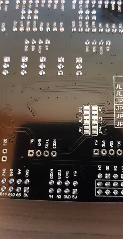
If you want to do so: when you look at the control board like on this picture you have to shorten the two left-most pins of the sensor connector (blue and black wire on the photo) using a jumper or jumper wire. But be careful and don't mess this up otherwise you could shorten the 5V circuit which will probably destroy the board. You have been warned. You could also attach a switch to those pins and manually emulate the FINDA sensor.
revilor
on 31 Jan 2019
@0lympu5 I'm quite happy with how things are going. The Marlin part is working reliably and so does the MMU2 unit. I still have issues with about 5 to 8 out of 100 material changes. But that's fine for me at the moment because I now also have the PAT9125 laser sensor in the extruder working and so far 100% of material change issues have been detected either by the MMU itself or by the laser sensor. So with looks at the end result I'm getting perfect multi-material prints, but from time to time some manual intervention is required during the print.
I think most of the issues I have are due to the fact that I'm using a V6 knock-off hotend at the moment. I will soon replace it with a genuine E3D V6 and hopefully will have less issues afterwards.
revilor
on 31 Jan 2019
How was the laser module implemented and does it function as a type of check point after each change only or continuously throughout print
0lympu5
on 31 Jan 2019
Please have a look at #12962. The sensor is on all the time and should detect any kind of filament motion issue. The most important part for me at the moment is when material change happens and issues there have been detected reliably so far. But further tests will be required to fine-tune the code.
revilor
on 1 Feb 2019
@revilor Thanks man. What is the correct diameter for the steel ball beneath the FINDA sensor? I didn't get one in the clone kits and I couldn't find information online. Thanks!
DimitarKrastev
on 1 Feb 2019
@revilor I've been reading into your work for the laser sensor and as I am still waiting for my mmu2 to arrive, I wanted to know how you included the sensor in your set up, such as wiring and whether it is included in your marlin branch for the mmu2
0lympu5
on 1 Feb 2019
@DimitarKrastev I use a 7.5mm steel ball. 7mm should also be fine but 8mm will usually not fit into the slot.
revilor
on 1 Feb 2019
@0lympu5 No, the laser sensor stuff is not in the MMU branch. It's an independent PR. I have a MK3 clone so it is the exact same setup as on the Prusa printers where the sensor sits in the slot on top of the extruder casing. On the printer board side it is wired to the I2C connector on the RAMPS. If you use the cable that usually comes with the sensor you have to swap white and blue wires on the 5 pin connector to make it fit.
revilor
on 1 Feb 2019
@revilor I found my finda sensor and now the load/unload is working great on the MMU side. Unfortunately I am still not able to get the serial connection to work. I haven't connected the reset wire, is it possible that is causing the issue? Also isn't there supposed to be a GND wire? Right now there is 5V, RX and TX, or maybe it is getting the GND from the main power cord from the PSU? Do you mind to have a chat in some IM. I think I am getting pretty close and I am missing something really small.
Thanks.
PS. Does this serial config look OK to you? I am trying to use Serial 1 on pins 18 and 19. Also what the difference between the two defines? Why are they two?
#define INTERNAL_SERIAL_PORT 1
#define MMU2_SERIAL internalSerial
DimitarKrastev
on 1 Feb 2019
@revilor How did you flash your MMU board? Arduino IDE or Slic3r PE ? Also should I burn bootloader> Sorry for the dumb questions, but I am not experienced with embedded.
DimitarKrastev
on 1 Feb 2019
I got it working. The homing is acting a bit strange. The barrel and the selector try to go their extreme positions and they produce very nasty sound every time. The printer says the MMU needs attention, but at the end it ends up OK. Is your homing sequence so unsmooth as well?
DimitarKrastev
on 2 Feb 2019
@revilor How do you slice the models for MMU?
DimitarKrastev
on 2 Feb 2019
@DimitarKrastev
On AVR boards by default only serial 0 for USB connection is active. Therefore you have to activate the serial port you want to use for the MMU2 with the first define
define INTERNAL_SERIAL_PORT 1
This creates a new serial named internalSerial, and that's what you set with
define MMU2_SERIAL internalSerial
to be used for the MMU2 connection. On 32 bit boards which usually have all the available serials enabled by default you would only set
define MMU2_SERIAL Serial1
Regarding the homing sequence of the MMU2: homing of the idler barrel is not too loud with my unit, but the selector is another story. Sometimes it will home to the right which is a nice and smooth operation. But most of the time it homes to the left - well, I would not call it homing, it just slams the selector against the wall on the left - and then it is very noisy. So far I was not able to figure out how the homing direction is chosen but homing to the left - at least in the way it is done at the moment - I consider a bug in the MMU firmware.
By the way: if you operate the MMU at 12V and have not done yet, also try
define MMU2_MODE_12V
which should make the MMU less noisy.
For slicing from my point of view there is only one option at the moment and that is Slic3r Prusa Edition. I use 1.42 alpha1. I have the MMU2 sitting on a MK3 clone, so this is a perfect fit. If you don't have a Prusa printer or clone my recommendation would be to get your extruder as close to Prusa's as possible (meaning direct drive and E3D V6 hotend). Then the ramming sequences generated by Slic3r PE should also work for your setup. You for sure do not want to figure out those ramming sequence gcodes on your own.
revilor
on 2 Feb 2019
@revilor i have a slightly modified prusa r3 extruder but i have a very large printer for which i use a volcano instead of a normal e3d v6, i wont get my mmu2 unit until march. Do you think it will be an issue?
0lympu5
on 2 Feb 2019
@0lympu5 I definitely would love to use a Volcano in combination with the MMU2. But I have not tried and from my experience so far I think it will be very time-consuming to get it work, and I consider the probability very high it will not work at all. A Volcano with that long melt zone will be very tricky to deal with when it comes to finding a reliable and repeatable unload sequence that will allow the MMU to load the filament again the next time it is used without jams or any other issues.
So if you ask for my opinion or recommendation I would say: go for a regular heater block and a 0.6 or 0.8 nozzle. You might not be able to print as fast as with the volcano but you will have less issues when it comes to the MMU. With regard to the Volcano and multi-material the Palette+/2 is probably the better fit.
Also check out this thread in the Prusa forum.
revilor
on 2 Feb 2019
@revilor My experience with the selector is the same and I am running on 24V. I am using a Titan Aero extruder and I am trying to make it work with Simplify 3D and I think I am getting closer.
Can you post an example gcode with mmu that you successfully printed. I want to see how the filament is being changed. From that I believe I might be able to produce an universal set of scripts for Simplify 3D.
DimitarKrastev
on 2 Feb 2019
0lympu5
on 2 Feb 2019
@DimitarKrastev Here you go: MMU-test.gcode.zip This is a test print of five 15x15x15mm cubes, each tool uses different ramming settings for rammed volume: 9mm^3 for T0, 13mm^3 for T1, 18mm^3 for T2, 24mm^3 for T3, 32mm^3 for T4.
The ramming sequence is part of the purge tower gcode, so it might be a little bit diffucult to extract. Instead you could use the ramming sequence used in Prusa's firmware (and now also in Marlin) to unload filament from the LCD menu as a starting point for your scripts:
#define MMU2_RAMMING_SEQUENCE \
      {   1.0, 1000 }, \
      {   1.0, 1500 }, \
      {   2.0, 2000 }, \
      {   1.5, 3000 }, \
      {   2.5, 4000 }, \
      { -15.0, 5000 }, \
      { -14.0, 1200 }, \
      {  -6.0,  600 }, \
      {  10.0,  700 }, \
      { -10.0,  400 }, \
      { -50.0, 2000 }
Those are extrude distances in mm and feed rates in mm/minute and would translate to a toolchange script like
; move to purge position
...

; ramming sequence
M83 ; E relative

G1 E1.0 F1000
G1 E1.0 F1500
...
G1 E-10.0 F400
G1 E-50.0 F2000
G4 ; wait for E moves to finish
; ramming and unload from hotend done


T<n> ; tool change

; feed filament from the extruder gears to the nozzle, do purge sequence, etc.
@revilor Thanks for the info. I used it as a base and I am tweaking the ramming sequence. I am also having trouble with the restart distance once the filament has reached the extruder. It seems it is pretty inconsistent. There is either not enough filament to complete half of the purge tower layer or there is too much which causes a blob so big that knocked my BLtouch and broke its mount. How are you handling the purge towers?
DimitarKrastev
on 3 Feb 2019
@DimitarKrastev For me the purge towers are handled by Slic3rPE and it works just as expected.
When you have inconsistencies with the purge I would point to the calibration of the MMU2. I'm quite sure you did this, but just to have it mentioned here and also for future reference: the procedure is laid out in chapter 6 of Prusa's 3D Printing Handbook. You need a consistent calibrated distance for all five MMU2 filament channels.
For the direct drive extruder of the Prusa printers you calibrate for the filament to just reach the Bondtech gears. When filament is loaded the MMU2 will transport the material the calibrated distance down to the gears. In a second step it will push the filament a few millimeters into and beyond the gears. The extruder stepper is disabled for this purpose to reduce the resistance of the drive gear.
In your case with the Titan Aero I wonder if maybe the MMU2 is not able to push the filament in because of the higher resistance the geared drive has. Or maybe it works some time and some time it does not an that's the cause of the inconsistencies you get. You could try to calibrate the MMU2 to stop the filament transport slightly above the extruder gears so that in the second step it will move the material just far enough for the Titan Aero to grab it but does not try to push the filament all the way in between the drive gears.
Another possibility could be that the MMU pulleys are grinding into the filament because of issues in the filament path or - again - in the calibration. This could cause problems the next time the filament is loaded because the pulley will have less or no grip at the grind mark and will therefore transport less material than required.
revilor
on 3 Feb 2019
@revilor The mmu2.cpp at Marlin bugfix-2.0.x line seems to be broken.
I've just got the code, it stopped working. The earlier code in your fork worked fine.
It is due to the wrong timeout , MMU_P0_TIMEOUT (3 secs_, being used to unconditionally.
It is supposed to be used only for P0 command, so everything times out.
I've worked my way around it but did not trace how it got to the Marlin bugfix-2.0.x line,
kursatu
on 5 Feb 2019
@revilor I have calibrated the MMU bowden length. My problem was that I overtightened the MMU and it was grinding sometimes. Anyways, filament loads are 100% consistent now.
The problem is unloading. The Prusa ramming sequence is obviously not working well for the Titan Aero. I tried just around 300 attempts to get the sequence right. At the end it turned out that waiting 1-2 seconds and then slowly pulling out the filament resulted in the most clean filament. Unfortunately that works around 20-30 times and then jams. But even with all the ramming sequences I tried, the filament gets out with relatively long string at the end that either causes it to jam immediately or over time (10-20 filament changes).
I guess just keep trying to nail the sequence will solve the issues, but it is really frustrating.
Also when the MMU fails to change the filament and print is paused if I dont rush to fix it within a minute or so the print is gone. When I fix the issue I am unable to resume the print. The MMU initially has the orange led lid. When I fix the problem it starts flashing green and orange, but the print doesn't resume. How should I resume a print if it stopped for such reason?
Thanks
DimitarKrastev
on 5 Feb 2019
@kursatu Thank you for the info. When my branch was merged Scott from his point of view optimized the code and reduced the two different timeouts to just one, unfortunately to the shorter one of the two. It should work when you change the value of MMU_P0_TIMEOUT to the same value as MMU_CMD_TIMEOUT. I have a fix already in my branch but looks like it did not end up in the main line. I'll check for that.
revilor
on 5 Feb 2019
@DimitarKrastev When the material change fails and Marlin tells you the MMU needs attention you have all the time you need. At least from Marlin because the printer will idle until the issue is fixed. Once you've fixed the issue and the MMU is flashing green and red/orange, press the right button on the MMU. It will load the filament, and as soon as Marlin gets the ok from the MMU, it will reheat the nozzle and continue the print.
Regarding the ramming sequence I can tell you it's a PITA even when Slic3r PE is doing all the work for you. In Slic3r PE you can choose a ramming time between 0 and 5 seconds in half second steps which in the end defines the total rammed volume. And you have to find the best value for each and any material. And by any material I mean _any material_, event different colors from the same brand often require different settings. I don't know the detailed setup of your printer, but if at all possible I would suggest to give Slic3r PE a try so you can print multi color models and don't end up in frustration over figuring out ramming sequences. And as I just said: you probably will have to do this again and again for all the materials you intend to use.
I have plans to check how the ramming/purge block generation is implemented in Slic3r PE to see if it is possible to extract that code to an external script or program of some kind and make it usable for other slicers. But it will take me some time to dig into the Slic3r PE code which I unfortunately do not have at the moment.
revilor
on 5 Feb 2019
@revilor Thanks! I haven't tried Slis3r PE yet. The problem I am seeing is that the ramming sequence is fundamentally different because the internal length from the bondtech gears to the tip of the nozzle is different. So let say we use Slic3r PE, it might retract less the needed length and in that case it will be "ramming" raw filament, or retract more than needed and will be "ramming" nothing because the filament is retracted beyond the bondtech gear. Is it possible to tweak the ramming sequence in more advanced way (say the length that is being moved up and down during the ramming) or is it just the duration of the ramming sequence? I got Simplify 3D to ram OKish and most of the time it produces nice filament shape with sharp tip. The problem is that the sharp tip is basically stringed filament which the MMU is breaking when it tries to unload the filament, but sometimes (once every 10-20 unloads) this string is harder and reaches all the way to the nozzle tip and since it is surrounded by the bodtech gear it is too hard to break off by the MMU and the unload jams, causing the MMu to grind on the filament on the MMU end and that causes a failure which requires the bowden to be unloaded and the filament cut behind the grinded point and load it again (annoying would be an understatement).
Ideas?
DimitarKrastev
on 6 Feb 2019
@DimitarKrastev I'm interested in your project because I'd like to add the MMU to my custom printer that uses a Titan Aero. Did you change the inner PTFE tube of the Aero hotend?
 valepe
on 6 Feb 2019
valepe
on 6 Feb 2019
@valepe I don't see how the internal PTFE tube is related. I did change it, because it was damaged by the extruder being hot without a fan, not because I need to change it for the MMU.
What you need to do though is to install a bowden coupling on the filament lever in order to securely attach a bowden tube to the Titan Aero. Something like this: https://i.ebayimg.com/images/g/N7IAAOSwz~paPTVV/s-l300.jpg
Then you need to widen the hole for the filament on top of the lever and screw it in. Everything else remains stock on the printer hardware side.
My current progress is that I generally made it work. The MMU unit is communicating properly with the printer, it changes the filament and continues printing. The problem is only with fine-tuning the filament extraction which causes jams. Unfortunately I am starting to think that it is not possible to be 100% reliable just because of the way it is designed to work. Pulling a filament out and hoping that ramming it against the extruder gear a few times will clean all stringing is just not sustainable. In a perfect world, this should be implemented using a filament cutter on the extruder side. This way you will ensure 100% consistent results (of course as long as the knife is sharp)
DimitarKrastev
on 6 Feb 2019
@DimitarKrastev thanks. I wrote about the inner PTFE because I read it in the Prusa installation of MMU2 where they stated to change the inner PTFE tube of V6 hotend.
Before screw the bowden plug should I insert a PTFE tube in the lever?
Could be these jams depend of different hotend or the MK3 has these jams also?
valepe
on 6 Feb 2019
@valepe No, I will send you a picture once I get home.
DimitarKrastev
on 6 Feb 2019
@DimitarKrastev It might be a misunderstanding on my side, but if you do the ramming by retracting the filament beyond the extruder gears and then move it back against the gears you are doing it completely wrong. The chance for stringing in this case I would consider close to 100%. The ramming has to happen in the hotend and the magic there is to have the right sequence of retract and extrude moves so you do not get any stringing when you finally transport the filament out of the hotend. Here is one example sequence produced by Slic3r PE
;--------------------
; CP TOOLCHANGE START
; toolchange #1
; material : DEFAULT (PLA)
;--------------------
; CP TOOLCHANGE UNLOAD
G1 X229.250 Y198.500
G1 F1461
G1 X223.170 E0.2816
G1 F1583
G1 X216.583 E0.3051
G1 F1791
G1 X209.128 E0.3453
G1 F2069
G1 X200.514 E0.3990
G1 F2469
G1 X190.236 E0.4761
G1 F2991
G1 X177.786 E0.5767
G1 F3513
G1 X170.750 E0.3259
G1 Y197.840 F7200
G1 F3513
G1 X178.335 E0.3513
G1 F3965
G1 X194.838 E0.7644
G1 F4278
G1 X212.644 E0.8248
G1 F4400
G1 X229.250 E0.7692
G1 Y197.180 F7200
G1 F4400
G1 X227.543 E0.0791
G1 E-15.0000 F6000
G1 E-14.0000 F1200
G1 E-4.0000 F600
G1 E-2.0000 F360
M104 S215
G1 Y196.520
G1 X202.543 E10.0000 F3231
G1 X227.543 E-10.0000 F2908
G1 X196.293 E10.0000 F3150
G1 X227.543 E-10.0000 F2756
G1 X185.877 E10.0000 F3085
G1 X227.543 E-10.0000 F2571
G1 E-50.0000 F2000
G1 Y196.600 F2400
G4 S0
T1
Important are the E moves, the X/Y is just to distribute the extruded/rammed filament on the purge block. So first it extrudes slight amounts of filament to build up pressure in the nozzle. Then some heavy retraction moves are done to transport the filament to the cooling position where it is moved up and down several times before the final retraction move happens to bring it above the extruder gears for the MMU to unload.
revilor
on 6 Feb 2019
@DimitarKrastev I forgot another important point: you can configure in Slic3rPE how far away from the nozzle the extruder gears are, so it should be possible to use it for your setup too. Go to _Printer Settings > Single extruder MM setup_ and change the value for _Filament parking position_ to a value that fits your needs.
revilor
on 6 Feb 2019
Chris Riley has a great video on the MMU2: https://www.youtube.com/watch?v=XH-F8h7Y1tM
revilor
on 7 Feb 2019
I got bored waiting for my mmu2 to ship from prusa so I built ,myself another printer. In doing so my steppers where limited by 12v power supply and dude to the build volume of nearly 1000 x 1000 and print speed of 120m/s, I changed to a mks gen 1.4 with tmc 2130 and a reprap full graphics display, all working well apart from I still need to work on sensorless homing for dual y axis drivers.
My question is, does anybody have a working set up with mks gen 1.4 and a full graphics display?
I know @revilor has a working ramps 1.4 board, and in order to use with conjunction with sd support I'd need to move endstop positions for my spare ramps for mmu2 communication. Will this be the same,e for mks gen?
0lympu5
on 9 Feb 2019
@0lympu5 I work with a MKS gen v1.2 and I have a 2004 discount LCD. But I had a very bad experience when I put working the full graphics. I posted here before:
"I'm running Marlin with Mega 2560 and discount 20x4 LCD and everything is fine and when I put the full graphics on my board when I start printing the temperature becomes unstable because the Arduino supposed to be overloaded and the PID didn't work well. On SD menu append the same. Too slow, so I want to upgrade the machine."
FNeo31
on 9 Feb 2019
Thanks @FNeo31 hoping that with a 1.4 it might not be a problem or see if not pid tuning hotend will fix. I know people who use similar setups so hopefully I won't have an issue.
Next thing is if mmu2 womt like my 800mm bowden tube
0lympu5
on 9 Feb 2019
The MMU version that I'm developing I don't care about the length of the PTFE pipe because this length is controlled by the printer on tool change zone
FNeo31
on 9 Feb 2019
I wanted a genuine mmu2 and then I can use that to develop my own
0lympu5
on 9 Feb 2019
@0lympu5 I created videos of url you found before. https://www.youtube.com/watch?v=h3JJ5Eu-AH0
I am testing MMU2.0 for keyestudio MKS Gen V1.4 like movies.
At the moment I fork the latest firmware of @revilor and test up to full graphic board display and single color printing according to SD card specifications.
However, even if sending the T command, the MMU does not work so I have not reached the test of the multiprint.
 airking7
on 10 Feb 2019
airking7
on 10 Feb 2019
Guys if anyone wants a extruder working without any block of filament you can download and print.
Just put the filament and print.
I design this to be easy to load filament for MMU.
All necessary parts on description
FNeo31
on 11 Feb 2019
@FNeo31 similar to prusas mk 2 extruder at a glance
0lympu5
on 11 Feb 2019
It's same way of thinking, the big difference is the base part for compatibility and the radial fans to have more flow on coller and on the hotend
FNeo31
on 11 Feb 2019
I use a setup with 2 ceramics too fast printing (at the moment printing at 6000mm/min and can be improved)
For this I needed to add more air flow.
So all the design was made with this vision and to be possible to use with MMU
FNeo31
on 11 Feb 2019
@airking7 I noticed something strange. I also failed to communicate with the MMU 2.0. I did a few changes, INCLUDING enabling the debug mode and it started working. Then I changed again a few things at once including disabling the debug mode (I know it is a bad practice to change more than one thing at a time) and it stopped working again. Reenabling the debug mode of the MMU in the config restored the connection. I didn't put too much thought at the time as I needed debug mode anyway to see what is going on during my tests, but now I am wondering if it has a connection. Please try with debug mode enabled and let us know if it changes anything.
DimitarKrastev
on 11 Feb 2019
@airking7 Can you please be more specific in what you are trying to do and what is not working. Because in your video everything seems fine and works as expected.
revilor
on 12 Feb 2019
By the way: as the MMU2 code is now merged to the main line 2.0 you can also open a separate issue in the Marlin tracker if something is not working with the MMU2 on your side. To enable me to help you please describe as detailed as possible what your printer setup is, what is not working as expected, and don't forget to attach your Configuration.h and Configuration_adv.h.
revilor
on 12 Feb 2019
@revilor, a new challenged has been introduced by prusa. They announced recently all new mmu2 orders or pending ones are to be upgraded to include the mmu2s features. Not much change to the mmu2 but a new extruder has been designed to replace the sometimes poorly functioning laser sensor.
It now uses a optical / mechanical hybrid. I will attach a link to the article later
0lympu5
on 12 Feb 2019
0lympu5
on 12 Feb 2019
Thank you for the link. So from my understanding there will be no changes to the MMU2 unit itself and also not the the communication protocol I guess. The only change is the new extruder and I don't get what they are doing there. From my experience with the MMU2 there are two issues with material changes
- the filament does not reach the extruder
- the filament won't feed into the hotend because the previous ramming sequence created a tip slightly too thick in diameter
The PAT9125 laser sensor can detect both. It's not perfect because it can't "see" certain filaments like some PETG and transparent material. But there are mods from MMU2 users which have the sensor look onto a bearing moved by the filament which still gives you all the possibilities the PAT9125 has - and this is an amazing piece of sensor hardware - for any kind of filament with close to 100% reliability because detecting motion of stainless steel is what the sensor was designed for in the first place.
And what does Prusa? Do they adapt one of those clever mods. No, what Prusa does is to throw the PAT9125 out of the window and replace it with a stupid switch. Well, it's an optical switch, but still. So the Prusa firmware on the MK3s will now able to check if the filament reached the Bondtech gears by using some weird lever construction on the extruder idler clap to trigger the filament switch. That's one step forward for all MK2.5/MK3 users because so far there was no sensor at all. Well, physically there was, but if a MMU2 is present the laser sensor is disabled.
But no longer can the firmware detect jams or help with the second issue from my list above where the filament will get stuck before it reaches the nozzle. And therefore I do not recommend to follow that road if you are using the MMU2 with Marlin.
What I do recommend is to place some encoder-style sensor in the filament path of your printer. The optimal place would be in or on top of the extruder but anywhere else is still better than to have no sensor at all. Even a simple switch is better than nothing.
Since I have the PAT9125 working with Marlin on my printer I had not a single failed multi-material print (well, I had failed prints, but those where caused by Octoprint and other external factors). There are still issues and 2 to 3% of all material changes fail. In the end it's an analog process with lots of variables, so 100% success rate is almost impossible to reach from my point of view. But those failures are detected either by the MMU2 itself or by the laser sensor, which allows me to fix them manually and then continue the print.
revilor
on 13 Feb 2019
At the moment I have a r3 extruder printed and a laser sensor on its way, so I'll try that one first because I feel like there are more options with that sensor
I ordered my mmu2 from prusa so soon I'll have both to test.
I don't see how the new sensor is better as they seems no way for it to test for a jam
0lympu5
on 13 Feb 2019
@0lympu5 the reason of this change from prusa is transparent filament troubles
FNeo31
on 13 Feb 2019
As we talked about the PAT9125: should you plan to buy a MK3 laser sensor PCB from the usual sources in China: check the product photos very carefully because there are two versions around. If you plan to place the sensor inside a MK3 extruder you need the one on left. The other one has the pin header soldered the wrong way and will not fit.
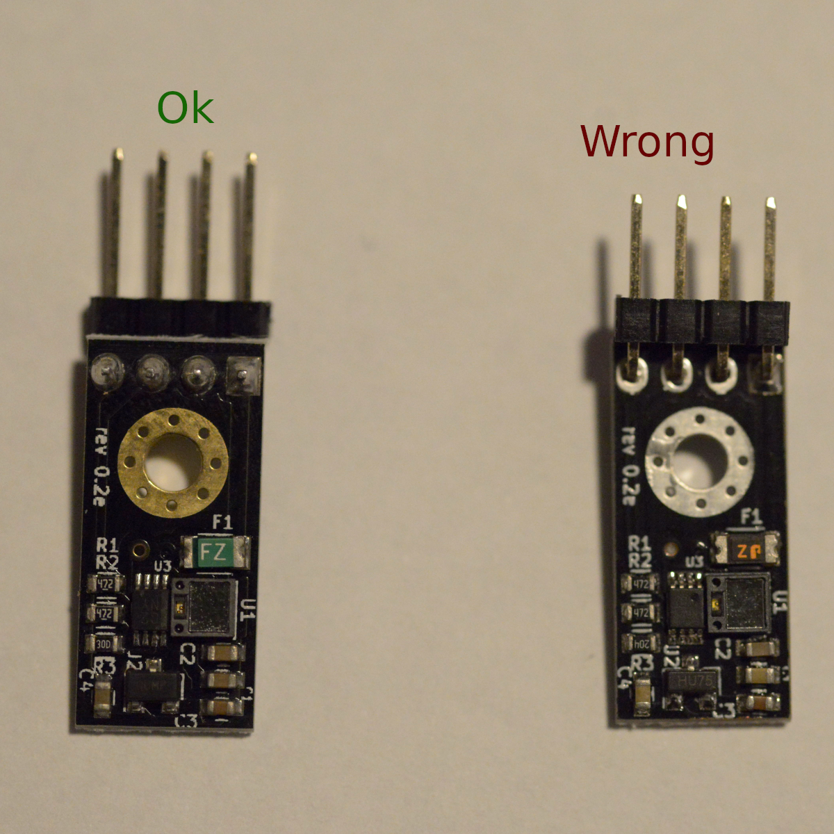
Also check for the label rev 0.2e as there are also offers for rev 0.2 which probably will not work correctly as there was a pull-up resistor missing in that revision.
revilor
on 15 Feb 2019
@revilor are there any hardware differences apart from that, I ordered mine a while ago but don't mind changing the headers over if required
0lympu5
on 15 Feb 2019
@revilor The previous movie was the version tested in early January, at this time it sent the command from the PC without LCD and the MMU tool change only worked.
Now I am adding a full graphic LCD · filament sensor and testing it.
I changed the communication with the MMU to the TX RX 1 pin, even if I instruct the tool change from the PC · LCD controller, the unit and the board can not communicate and the unit is not moving.
Configuration, Configuration_adv and pins_RAMPS include zip file
@DimitarKrastev I think they probably have the same problem. But even if I change debug mode etc, I will not move.
airking7
on 16 Feb 2019
@0lympu5 the only difference are the pin headers as long as both are revision 0.2e. You can also get revision 0.2 which misses a pull-up resistor and probably will no work correctly.
revilor
on 16 Feb 2019
@airking7 Your configuration works fine with my test setup. Did you check if you by accident swapped the RX and TX wires for the serial connection?
revilor
on 16 Feb 2019
@revilor Yes, I did not move even if I did it.
Sadly when I was checking the TXRX for replacement, the LEDs on the board were all orange lit. Probably an error? When turning on the power again, the idler motor ceased to move. Do you think it is a malfunction of the motor driver?
airking7
on 18 Feb 2019
@airking7 I have not built mine yet but I remember @revilor talking about swapping cables around in the provided prusa wire harness
0lympu5
on 18 Feb 2019
@airking7 The idler not moving on power up is not a good sign, but maybe you just disconnected the stepper cable when fiddling around with the serial cable?
revilor
on 18 Feb 2019
@airking7 I wrote up how the startup sequence should look like. Please check where the sequence ends in your case. It's possible we are talking about the serial connection but in the end it's the reset that is not working. So let me know at what point in the sequence the behavior is different on your side and what exactly is different.
revilor
on 19 Feb 2019
@revilor have you checked the new sensor design for Prusa i3 Mk3s? They added a lever to the top of the bond tech idler "door" and a small tower that surrounds this lever with the sensor on the top facing down. The idea is that when the filament is physically between the gears, the idler moves a bit to the side causing the lever to tilt and the sensor detects that. It looks like a much better way to detect if the filament reached the gears. Also the Bowden tube calibration is virtually non existent. Whatever length you put, when the sensor detect the filament, the MMU stops pushing immediately.
I think this design is not released yet as there is no manual and the guys from the support said "soon"t. Yesterday I found the parts in the mk3s stl file zip and reverse engineered how to assemble it. It looks like it is working great. I had a print failure but it was due to the mmu pindar accidentally detecting the filament as out while it was still there, but the extruder part looks promising.
DimitarKrastev
on 19 Feb 2019
@revilor Me being dumb, I have used the MK3 / MMU 2 profile and hence the problems I had. With the new sensor design and the new MK3S/MMU 2S profile in Slic3r PE I already printed 2 models with zero hickups on filament change with over 200 filament changes per print.
DimitarKrastev
on 22 Feb 2019
Hello, looking for some inspiration on how people have mounted their mmu2 units or plan to and organised their spools.
Mainly interested in if anyone has mounted the mmu2 to a hypercube or corxy design as that is rather similar to the design I have tia
0lympu5
on 25 Feb 2019
is there a guide to setting up marlin for mmu2? having errors poping up
0lympu5
on 26 Apr 2019
Hi,
There is those links from @revilor to start:
https://revilor.github.io/MMU2-Marlin/wiring
https://revilor.github.io/MMU2-Marlin/RAMPSserial
https://revilor.github.io/MMU2-Marlin/debugging.html
On my side everything seems working, i’m still in the calibration process for my printer.
What are your error messages ?
 Minims
on 26 Apr 2019
Minims
on 26 Apr 2019
at the moment i was getting was getting a range of errors, i have just re downloaded the sources and arduino so i will let you know
0lympu5
on 26 Apr 2019
@Minims
here is the error message
Arduino: 1.9.0-beta (Windows 10), Board: "Arduino/Genuino Mega or Mega 2560, ATmega2560 (Mega 2560)"
sketch\src\moduleplanner.cpp: In function 'reset_acceleration_rates':
sketch\src\moduleplanner.cpp:2880:1: internal compiler error: Segmentation fault
}
^
Please submit a full bug report,
with preprocessed source if appropriate.
See http://gcc.gnu.org/bugs.html for instructions.
lto-wrapper.exe: fatal error: C:\Users\Kiera\AppData\Local\Arduino15\packages\arduinotools\avr-gcc\5.4.0-atmel3.6.1-arduino2/bin/avr-gcc returned 1 exit status
compilation terminated.
c:/users/kiera/appdata/local/arduino15/packages/arduino/tools/avr-gcc/5.4.0-atmel3.6.1-arduino2/bin/../lib/gcc/avr/5.4.0/../../../../avr/bin/ld.exe: error: lto-wrapper failed
collect2.exe: error: ld returned 1 exit status
exit status 1
Error compiling for board Arduino/Genuino Mega or Mega 2560.
This report would have more information with
"Show verbose output during compilation"
option enabled in File -> Preferences.
Here is all that i have done
- changed extruders to 5
- Defined Singlenozzle
- Defined Prusa MMU2
- Defined Nozzle Park
- Defined Advanced Pause Feature
- Defined MMU2 12v Mode
- Defined MMU2 LCD Menus
- Defined Reprap full graphics display
0lympu5
on 26 Apr 2019
Just for information, mmu2 option is not compatible with power loss recovery :
https://github.com/MarlinFirmware/Marlin/issues/13637
And you might have a lot of warning without failure about toolchange zraise : https://github.com/MarlinFirmware/Marlin/issues/13638
Minims
on 26 Apr 2019
Hum can you go back to arduino 1.8.8 or 1.8.9 and not the 1.9 beta version ?
Minims
on 26 Apr 2019
I thought it had to be arduino 1.9 for marlin 2.0
0lympu5
on 26 Apr 2019
On my side i prefer vscode with PlatformIO, but arduino 1.8.8/9 is ok for me on mac
Minims
on 26 Apr 2019
same issues with arduino 1.8.9 as 1.9, are you able to share your working mmu2 fw to see if its a code issue or marlin?
Is the PlatformIO the online version of arduino?
0lympu5
on 26 Apr 2019
No it’s a plugin for microsoft visual code : https://platformio.org/platformio-ide.
My current setup for a coreXY : https://github.com/Minims/Marlin/tree/CoreIN-bugfix-2.0.x-dual-stepper-bltouch-mmu2
Minims
on 26 Apr 2019
thank you, i have just retried it and it complied fine but i shall have a look at yours, my set up at the moment is a 600 x 300 printer, dual y steppers, tmc 2208 and full graphics display
0lympu5
on 26 Apr 2019
sorry for being a bit of a brick wall with code but im used to the old marlin, if i wanted to edit the pins for ramps how would i do so, i need to move a couple of endstops and use z+ and z- for rx and tx connections
0lympu5
on 26 Apr 2019
Mine is 310x310x420 with ramps, full graphics display, dual z stepper drv8825, xy tmc2208, ext drv8825, bltouch, psu at 12v, bowden
Minims
on 26 Apr 2019
Like me, look at my diff here : end of page)
https://github.com/Minims/Marlin/commit/a13b3907f7f2474ada712a4ac6022dd829e7ea67
Zmin on Ymax, mmu2 on zmin and zmax
Minims
on 26 Apr 2019
i believe that was my plan
0lympu5
on 26 Apr 2019
Ive just grabbed a spare ramps + mega + display for testing, uploaded my code and only got stuck on boot up screen so trying to install yours
0lympu5
on 26 Apr 2019
Set internal serial port from 2 to 1
Minims
on 26 Apr 2019
okay but why?
0lympu5
on 26 Apr 2019
Serial 2 is pin 16/17 used by lcd, serial 1 is pin 18/19 for zmin/max
Minims
on 26 Apr 2019
Ah okay, by your code, it already is
0lympu5
on 26 Apr 2019
Thank you for you help so far, i have uploaded your code and simple changed the language this far, i will need to remove the dual z steppers and replace with dual y, i notice and auto align feature for your z axis, is that an option or automatic due to having dual steppers for a single axis?
0lympu5
on 26 Apr 2019
No problem, auto z align is an option in lcd , g34 is the gcode to align both side automatcly. Not necessary, but very cool feature. I moved to marlin2 for that, and now for mmu2. Let me know if you success with mmu2. I am still on it. Bowden is a bit more difficult to setup
Minims
on 26 Apr 2019
Ah okay, for the moment i have two endstops wired in series for the y axis with a buff to catch
0lympu5
on 26 Apr 2019
@Minims can i ask what pins you used and for what to connect the mmu2 to ramps please?
0lympu5
on 26 Apr 2019
As i remember, 12v is connected direct to psu.
Blue 5v to 5v of Zmax ,white to zmin, green to z max and brown to d44 in aux2
Minims
on 26 Apr 2019
I cant look at code anymore tonight as my laptop just ran out of battery but going to tweak a few things and then start plugging it together, how can I edit the pins file now that marlin 2 has only config and config adv. Just because I'll need to use your z2 for my y2
0lympu5
on 26 Apr 2019
That.s why i use vscode and platformio.
But on the file src/pins/pins_RAMPS.h with an editor’ make your changes, save, quit. Reopen marlin.ino, compile, upload, and it will work
Minims
on 26 Apr 2019
Ah okay, thank you, so used to it all being there in arduino
0lympu5
on 26 Apr 2019
@Minims I now have my mmu2 plugged in with a slightly modified version of your marlin, first filament load works fine, even got an error for having no filament at the time, now i need to disable checking for hotend temp so i can continue testing without the printer.
One question, does your barrel seem to make quite a large amount of noise and knock at least 5 or more times before homing?
0lympu5
on 27 Apr 2019
@0lympu5 About disable checking temp, you use this :
M302 P1 ; disable cold extrusion checking
Yes my barrel has the same beahvior. I think it's the sensorless homing with TMC2130.
The MMU2S Manual says :
During homing procedures, a repeated clicking can be heard. Don ́t worry about it, it’s a part of the procedure.
Minims
on 27 Apr 2019
Ah thats fine then, repeatedly tested it today with what seems like success, i ended up finding a resistor that gave a temp of 240.
I also connected the mk3s filament sensor that came with the kit and was looking into the other features of the mmu2, i cant see how to get the mmu to continually load to nozzle till the sensor on the extruder is tripped and the spool join feature.
0lympu5
on 27 Apr 2019
@0lympu5 it's seems the feature that make a "continually load to nozzle" appears with mk3s/mmu2s. I have load the latest MMU2s firmware, but I think both feature are not implemented in marlin. Maybe the mmu2 marlin implementor @revilor can confirm this.
Minims
on 27 Apr 2019
I thought that as there are no mention of it in the code for the menu either
@Minims have you had any issue with the bowden calibration, ive hit a maximum length but i need more
0lympu5
on 27 Apr 2019
you mean length between mmu2 & extruder gear ?
Minims
on 27 Apr 2019
yeah, reached the max as the mmu2 wouldn't go any further so looking if there is a fw limit
0lympu5
on 27 Apr 2019
but i dont know how to open / edit hex files
0lympu5
on 27 Apr 2019
You have to rebuild from source, infos is in README :
https://github.com/prusa3d/MM-control-01
I have setup my max to ~110cm. Here is my 1.0.5 MMU2 Fw
if you want to try.
Minims
on 27 Apr 2019
Tbh I've tried the max length on the mmu2 and there is almost 700 mm between mmu2 and extruder so should be okay, cut the ptfe a little short to make sure it always hits the gears
0lympu5
on 27 Apr 2019
Is it possible to create a g code file that is purely just tool changes for like an hour, simple stress test of the mmu
0lympu5
on 27 Apr 2019
I think it can be possible. Gcode for tool change is :
T0
T1
T2
T3
T4
But this will only make change on MMU, so will load/unload from MMU to Gear.
If you want to make test from MMU to nozzle, You might need to add some gcode to make load & ramming sequence from gear to nozzle.
Minims
on 27 Apr 2019
Here is example for original Prusa , but later this has to be done by Slic3r as I understand. I have not go further for now.
; ramming sequence
M83 ; E relative
G1 E1.0 F1000
G1 E1.0 F1500
G1 E2.0 F2000
G1 E1.5 F3000
G1 E2.5 F4000
G1 E-15.0 F5000
G1 E-14.0 F1200
G1 E-6.0 F600
G1 E10.0 F700
G1 E-10.0 F400
G1 E-50.0 F2000
G4 ; wait for E moves to finish
; ramming and unload from hotend done

T<n> ; tool change

; feed filament from the extruder gears to the nozzle
M83 ; E relative
G1 E7.2 F562
G1 E14.4 F871
G1 E36.0 F1393
G1 E14.4 F871
G1 E50.0 F198
I remember seeing similar within the marlin 2 code, maybe slightly varying values,
Need to take it into work with me so I can get it back up and worming on my rig
0lympu5
on 27 Apr 2019
Hopefully they add the filament run out feature and being able to use teo filament sensors, but for the minute do you know of the best prints to use as initial calibration, I presume going from 2 filaments and progressing upwards
0lympu5
on 27 Apr 2019
I will try the Prusa example "Geecko". Originally used with 3 filaments, but I will replace the third color with the first one.
2 colors for the beginning seems a good idea to me.
The first thing is to have a working tool change during the print. I am block here.
1st unload ok,
2nd load to gears ok,
load from gear to nozzle before resuming print fails. it starts before filament reach my nozzle (Bowden tube of 60cm)
At this point I found that you have to manage a filament buffer, or auto rewind spool, because I have 2m of filament back on tool change...
Minims
on 27 Apr 2019
Yeah I'm designing a system to have 5 spools in a line on individual axle with a rewind centre, chucking the buffer straight out
For the filament issue you can individually load and calibrate each Bowden length, there were people who had similar issues, where every filament loaded to the nozzle fine apart from one
0lympu5
on 27 Apr 2019
Auto-Rewind Spool Holder found on #Thingiverse https://www.thingiverse.com/thing:3200204
- just the axle part
Universal Auto-Rewind Spool Holder found on #Thingiverse https://www.thingiverse.com/thing:3338467
- full spool holder
@minims
0lympu5
on 27 Apr 2019
I don't think you can calibrate the 5 filaments for gears to nozzle. if it possible I din't know how.
I have calibrate "bowden" length for the 5 filaments. I mean length from MMU to Extruder Gear. Filament can be catch by the E gear. This part is Ok.
Load Filament to Nozzle from LCD, is OK too for all 5 filaments.
I'm trying to tune "Filament parking position" in Slic3r as revilor suggest, but I had not enough time to make new tests for now.
Minims
on 27 Apr 2019
Auto-Rewind Spool Holder found on #Thingiverse https://www.thingiverse.com/thing:3200204
- just the axle part
Universal Auto-Rewind Spool Holder found on #Thingiverse https://www.thingiverse.com/thing:3338467
- full spool holder
@Minims
I'm looking to this one on my side : https://www.thingiverse.com/thing:3228827
Minims
on 27 Apr 2019
Sometimes have risk of noting
The first one I showed you or in fact both of them will re wind up to 8 full times which should be more than enough, I had a spool with a 1/4 left and less than 3 rotations pulled in atleast 750mm
0lympu5
on 27 Apr 2019
Ah yeah, I remember because you're using Bowden system, maybe over compensate by a little, and get the last section slow so if it's too far it can ooze out
0lympu5
on 27 Apr 2019
@revilor is there any potential to further expanding the mmu2 functionality in marlin 2, to include the same features as in the current prusa fw?
0lympu5
on 28 Apr 2019
Sorry folks, there will be no MMU2S support in Marlin from my side in the near future. For now I don't have the time to implement it and as my printer carries a Bondtech extruder at the moment I also do not have the hardware to test this kind of stuff.
For a bowden setup you would have to design your own (opto)mechanical "filament reached the extruder gears" sensor to make it work, so it's not just Marlin. And to find a generic solution in Marlin to support as many printers as possible and not just MK3 clones with a MK3S extruder will also take some time and effort I'm not able to invest on a voluntary basis at the moment.
revilor
on 28 Apr 2019
@revilor did you get rid of your laser sensor then ?
0lympu5
on 28 Apr 2019
@0lympu5 No, the laser sensor sits on top of the Bondtech
revilor
on 29 Apr 2019
@revilor Does it function as a usual filament sensor, the same as the mk3s one I have hooked up, no communication with mmu2 but will detect a filament run out if mmu2 finda doesn't or doesn't load correctly ?
0lympu5
on 29 Apr 2019
Cany anyone help me, I have a mmu hooked up and running well on ramps and @minims version of the firmware, using the R4 design with filament sensor.
The mmu has been calibrated with Bowden tubes to reach the extruder but once it reaches the jaws it continues to spin and even pick up speed, creating a lot of pressure inside the hot end, any ideas?
0lympu5
on 6 May 2019
R4 with IR Sensor like MK3S ?
Is it while printing ? or while 'load filament to nozzle' from LCD Menu ?
Minims
on 7 May 2019
yes it is the r4 with the chimney set up supplied with the mmu2s kit.
Only noticed while using the lcd, re calibrated bowden length and i know its not that, have not tried a print yet as thought it would fail due to this issue.
0lympu5
on 7 May 2019
Have you kept my value for load to nozzle ? because it's for my Bowden setup. you have to go back to original value. same thing for ramming sequence.
Minims
on 7 May 2019
Is that the section within config.adv because o thought it was that a first but compared it to another file and it was the same but maybe I got the files mixed up, had a few attempts tbh, any idea what the original values should be?
0lympu5
on 7 May 2019
original value fitting MK3 (not S)
    #define MMU2_FILAMENTCHANGE_EJECT_FEED 80.0
    #define MMU2_LOAD_TO_NOZZLE_SEQUENCE \
      {  7.2,  562 }, \
      { 14.4,  871 }, \
      { 36.0, 1393 }, \
      { 14.4,  871 }, \
      { 50.0,  198 }

    #define MMU2_RAMMING_SEQUENCE \
      {   1.0, 1000 }, \
      {   1.0, 1500 }, \
      {   2.0, 2000 }, \
      {   1.5, 3000 }, \
      {   2.5, 4000 }, \
      { -15.0, 5000 }, \
      { -14.0, 1200 }, \
      {  -6.0,  600 }, \
      {  10.0,  700 }, \
      { -10.0,  400 }, \
      { -50.0, 2000 }
I'm pretty sure those are the values I have
I'm presuming first number is speed and then distance ?
0lympu5
on 7 May 2019
first is distance, second is speed. It's relative values.
mk3s is a bit shorter than mk3. So if you have the correct values , I would try to replace :
{ 7.2, 562 }, \
by
{ 3.0, 562 }, \
Minims
on 7 May 2019
Okay, by that logic I might've seen the speed and not the distance, I did notice a load unload value in the filament config menu branch in the range of 500 to 600 so I must have your values on place somewhere
0lympu5
on 7 May 2019
Hello, I have a working Marlin MMU2S config. Question, does this version work like the newest Prusa version where it uses the filament sensor to know when to stop feeding? I am using the MK3S MMU2S extruder body with the IR sensor and extruder door lever.
 brotherchris
on 2 Aug 2019
brotherchris
on 2 Aug 2019
Hi @brotherchris :-),
This is working like the MK3 version (so before MK3s / MMU2s).
- No stop feeding until filament reach sensor.
- No Automatic Spool change at the end of the roll.
On my side I'm using MMU2S FW 1.0.5 and it works great (1.0.6 is in RC1, will be available soon).
I also use a MK3s R4 Body with IR Sensor, but I have some issue with that. Detection problem may be related to : https://github.com/MarlinFirmware/Marlin/issues/14337
Have you an issue too with the IR sensor on last Marlin2.0 master branch ?
I hope we will have a video soon about that ;-).
Minims
on 2 Aug 2019
Hi Chris :-),
This is working like the MK3 version (so before MK3s / MMU2s).
- No stop feeding until filament reach sensor.
- No Automatic Spool change at the end of the roll.
On my side I'm using MMU2S FW 1.0.5 and it works great (1.0.6 is in RC1, will be available soon).
I also use a MK3s R4 Body with IR Sensor, but I have some issue with that. Detection problem may be related to : #14337
Have you an issue too with the IR sensor on last Marlin2.0 master branch ?
I hope we will have a video soon about that ;-).
Hi,
I have an MMU2 clone (not S) running with an e3d titan without filament detection on the extruder.
If I understood your message, I can update the MMU2 firmware to an MMU2s firmware even if I don't have a filament sensor? Or do I have to install one?
 BastR
on 2 Aug 2019
BastR
on 2 Aug 2019
Hi @BastR,
MMU2 & MMU2s are the same (Electronic & Printed Parts). My IR sensor has some problems, so I disable runout for now, and yes it works with 1.0.5 FW. So without any filament sensor, it will work too.
Minims
on 2 Aug 2019
Hi @Minims ,
That's good news!
So I reformulate my question, if I install a filament sensor at the top of the extruder, I could use it to make the loading of the filament into the extruder more reliable and stop printing if there is no filament?
With a mechanical sensor, for example
BastR
on 2 Aug 2019
@BastR Yes, it will work like the mk3 with laser sensor.
You will confirm that the filament has reach the runout, but you won't be able to be sure that the gear get the filament. That's why i prefer MK3s design. You can try to trigger a mechanical end stop when the filament is loaded by the titan.
Minims
on 2 Aug 2019
Sorry if I am getting the wrong idea here, last time I checked we didn't have the function of detecting the filament reaching the extruder and automatic spool swapping on filament run out, is there new fw to support this with Marlin.
I bought a genuine mmu2 but they gave me a mmu2s so I have all the parts for either mk3 or mk3s extruder assembly, I have the mk3s fitted with a working filament sensor configured in marlin but I'm guessing there is more to do to get it to talk to the mmu control board
0lympu5
on 2 Aug 2019
To confirm but I'm quite sure:
- If using a MK3s body, IR sensor act as runout, but there is no callback to MMU2 to say, "OK I get it".
- But it will help if the mmu2 has not push the filament far enough. So the print will pause until you have fix it.
Minims
on 2 Aug 2019
@minims so the filament sensor will act in the same sense as any filament sensor would work in marlin, mmu2 or not. No filament print is paused, user interaction
With the auto spool runnout detection is it possible that will work as I may just need to update my mmu2s fw, from my understanding that feature is entirely mmu based and uses the finder probe
0lympu5
on 2 Aug 2019
@0lympu5
- No more filament = Pause Print, Park Head, Manual Action, Confirm with LCD
- SpoolJoin is not implement in Marlin2. I have look a the Prusa code, this is managed by the printer, not the MMU2.
- Fill until sensor is triggered is "just" Sensor 0, send 'C0' again.
Minims
on 2 Aug 2019
@Minims Thank you! This is exactly the info I needed. Yes, there will be a video, working on it today in fact. :) Thanks again.
brotherchris
on 2 Aug 2019
Hi Guys.
Not often I post but I'm looking at putting an MMU2 on one of my printers.
I have the MMU2 electronics talking to my test printer when my test printer has a Mega as the controller but for the life of me I can't get it to talk to my test printer when it has a Re-Arm as the controller.
I've tried the Serial settings as mentioned in this post but to no avail.
I can't go back to using Mega's as controllers in my printers as the increase in quality the Re-Arm's bring is unbelievable.
Would appreciate all suggestions as I know I'm probably missing something extremely obvious.
 paulluby
on 8 Nov 2019
paulluby
on 8 Nov 2019
@paulluby I had mine working in a ramps 1.4 and mega because the arduino had a serial connection to the endstops on that board. I have a re arm but never used it. I think from memory the serial ports are in a completely different location.
I use a skr pro now and use the serial connection for what would be a tft screen which needs tx and rx communication.
Also not in 32bit boards internal serial isnt used just Serial1 etc
0lympu5
on 12 Apr 2020
@paulluby —
This Issue Queue is for Marlin bug reports and development-related issues, and we prefer not to handle user-support questions here. (As noted on this page.) For best results getting help with configuration and troubleshooting, please use the following resources:
- MarlinFW.org Marlin Documentation
- RepRap.org Marlin Forum
- Tom's 3D Forums
- Facebook Group "Marlin Firmware"
- Facebook Group "Marlin Firmware for 3D Printers"
- Marlin Configuration on YouTube
- Marlin Discord server. Join link: https://discord.gg/n5NJ59y
thinkyhead
on 12 Apr 2020
@0lympu5
Thanks, but have moved on from the MMU2 which I got working with an SKR V1.3 in the end as I moved on from the very limited Re-Arm board. MMU2 is a nice gadget but no more than that IMO. Too many things have to go right for it to work for me as I print oversize. My average own designed printer has a capacity of 410 x 410 x 410 mm. MMU2 is not reliable enough over a 5 to 6 day print that requires thousands of colour changes.
BTW I'm now using SKR V1.3's and SKR V1.1 Pro's on my printers. However the printer with the tool changer I have designed is using a GTR V1.0 with M5 V1.0 expansion board. So far 6 day multi-colour prints are a doddle and boringly reliable.
@thinkyhead
Thanks for letting me know 6 months after I posted ;)
paulluby
on 13 Apr 2020
@paulluby
would you be so kind to share with me your config (configuration.h and configuration_adv.h) for the SKR V1.3 I cant get my SKR V1.3 to talk to the MMU2s
 sima-it
on 13 Apr 2020
sima-it
on 13 Apr 2020
I have the same trouble recently,
Use Serial on MMU2 port and not Serial 2 to use TFT serial port
Put just first serial with -1 (usb) on configuration.h and disable the second.
And in my case the MMU2 start quicker than Printer so I need to reset the MMU2 after start up
If you want I can post my configs later.
Attention with the cable
On SKR to put the connector directly you need to change the cables order
Change from
Blue white green white brown
To:
Blue white white green brown
Vcc GND RX TX RST on connector
Attention in the MMU2 board is
Vcc RX TX GND RST
Blue White green white brown
Check the white wires with multimeter
FNeo31
on 13 Apr 2020
Can anyone help with an issue using prusa slicer? I have mmu setup properly and working with marlin but when printing it goes back to original settings. Like ramming distance
0lympu5
on 14 Apr 2020
@FNeo31 thanks disabling the second serial did the trick. I can now communicate. It would be very nice if you could post your config because it looks like something is still not working correct.
sima-it
on 14 Apr 2020
Can anyone help with an issue using prusa slicer? I have mmu setup properly and working with marlin but when printing it goes back to original settings. Like ramming distance
I have the same trouble with ramming and filament change correctly I think that the ramming sequence is on Marlin default so you need to change it on Marlin or like I will try make it manually and use M701/M702
FNeo31
on 14 Apr 2020
@FNeo31 ive adjusted the ramming sequence in marlin accordingly but when prusa slicer generates the gcode it only unloads a max of around 91.5, whereas i need about 115mm.
0lympu5
on 14 Apr 2020
Do you have runout sensor on the head of the printer or not?
FNeo31
on 15 Apr 2020
@FNeo31 fixed that issue, there is a setting in prusa slicer for filament unload pos. My next issue is that even tho I'm using a e3d v6 clone, the ramming sequence for unloading creates clogs above my heartbreak almost everytime
0lympu5
on 17 Apr 2020
@FNeo31 fixed that issue, there is a setting in prusa slicer for filament unload pos. My next issue is that even tho I'm using a e3d v6 clone, the ramming sequence for unloading creates clogs above my heartbreak almost everytime
I'm right there with you. I just got it working on my GTR board. My goal is to use M5 and skip the prusa board. Or use my tft35 extra serial port
 Maynardnaze
on 17 Apr 2020
Maynardnaze
on 17 Apr 2020
@0lympu5 I spent a lot of time to find the right parameters for the MMU2 with Marlin, today I manage to print multilateral STL relatively well, I would say that I have a success rate > 98%.
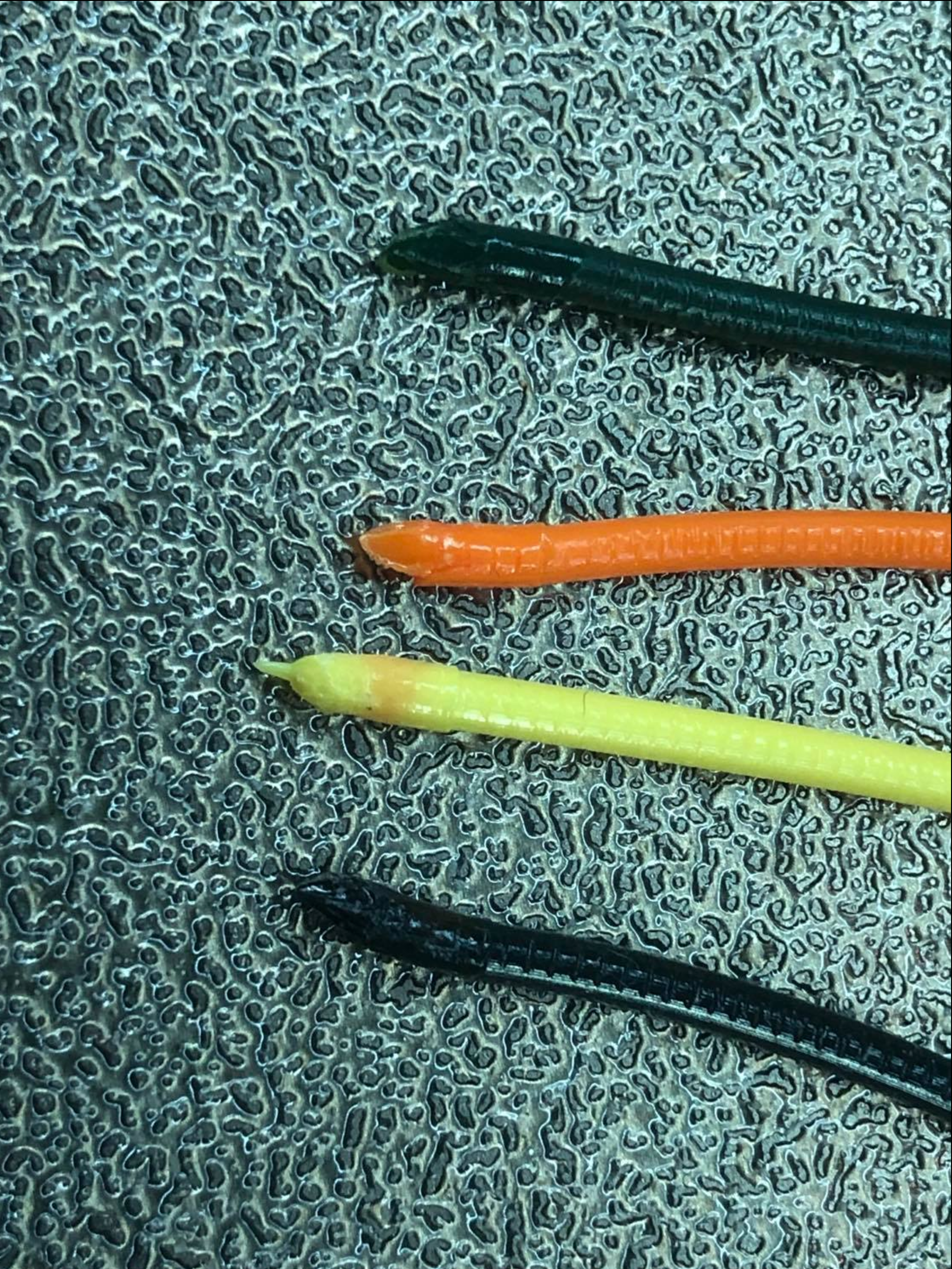
To make good tips and avoid clogs, you can work on those points:
e3dv6 for MMU2 has a different heatbreak, the internal diameter is smaller to make good tips (see https://www.reddit.com/r/prusa3d/comments/9u4ad5/mmu2_woes_learn_from_my_stupidity/), you can find it on e3d-online
hotend ptfe need to be trimmed like this https://help.prusa3d.com/en/guide/how-to-trim-ptfe-tube-original-prusa-i3-printers_22424
Finally, you can take a look at this feedback which corresponds to some improvements I have been able to make and I confirm that it works: https://www.hcd.net/prusa-mmu2s/Prusa-MMU2S-Reliability-Modifications.htm.
@FNeo31 @Maynardaze
To make SKR 1.3 works with MMU2, look:
https://github.com/MarlinFirmware/Marlin/issues/16500
and
BastR
on 17 Apr 2020
@BastR thank you u shall have a look when or if u get those issues. Atm gcode tool switches work fine, but when unloading from the lcd it leaves a small blob of the filament at the top of the heatbreak. Stopping me loading the next filament. I dont think heat creep is the cause as I have a high powered 4020 fan on the heatsink and the extruder is bondtech so stepper heat doesnt get translated to the gear
0lympu5
on 17 Apr 2020
@BastR I have connection with SKR 1.3
My actual trouble is the same as @0lympu5 put the changing working well.
At the moment my extruder is a custom made extruder with e3dv6 and dual gear. But at the moment without sensor on the head. So I needed to calibrate each filament length to arrive in right position on extruder.
Custom Extruder here:
https://www.thingiverse.com/thing:3418310
My struggle is the ramming and the sync between printer and MMU2 on filament change. I tried M600 but need every time a controller check to continue so I'm trying to manage with M701 and M702 to don't need the runout sensor. But to work the ramming need to be good to don't stack in pipes. I'm trying PLA at first.
On prusa slicer without wipe tower don't make slicer ramming moves
FNeo31
on 17 Apr 2020
@FNeo31 I've looked at changing to a purge bucket and therefore I let the extruded slightly over load and unload around an extra 50mm just so I'm certain the filament clears the extruder
0lympu5
on 17 Apr 2020
@0lympu5 ok so let me get this straight, you have a problem with the ramming sequence but only from the LCD command, during printing everything is fine?
BastR
on 17 Apr 2020
@0lympu5 I spent a lot of time to find the right parameters for the MMU2 with Marlin, today I manage to print multilateral STL relatively well, I would say that I have a success rate > 98%.
To make good tips and avoid clogs, you can work on those points:
- e3dv6 for MMU2 has a different heatbreak, the internal diameter is smaller to make good tips (see https://www.reddit.com/r/prusa3d/comments/9u4ad5/mmu2_woes_learn_from_my_stupidity/), you can find it on e3d-online
- hotend ptfe need to be trimmed like this https://help.prusa3d.com/en/guide/how-to-trim-ptfe-tube-original-prusa-i3-printers_22424
- Finally, you can take a look at this feedback which corresponds to some improvements I have been able to make and I confirm that it works: https://www.hcd.net/prusa-mmu2s/Prusa-MMU2S-Reliability-Modifications.htm.
@FNeo31 @Maynardaze
To make SKR 1.3 works with MMU2, look:
16500
and
15119
Nice tips!! Did you change MMU_RX_SIZE?
Maynardnaze
on 17 Apr 2020
Yesh it seems that way. I'm rather confused by it myself but in realistic terms I can edit the ramming sequence to be whatever I want in the firmware as when printing a multi material print. The slicer generates it's own ramming sequence.
The standard ramming sequence in marlin, seems to back out the filament a long way so I might reduce the amount it backs out before ramming
0lympu5
on 17 Apr 2020
@Maynardnaze no I use the default setting, 16 in my case (with SKR PRO).
@0lympu5 There are 2 "kind" of ramming sequence, the one used for commands executed from the LCD, and the one used during printing.
The ramming sequence used for the LCD commands is the marlin in the configuration_adv.h, while the ramming sequence used during printing is in PrusaSlicer.
If the filament remains stationary in the nozzle for a "long" time, there is a good chance that it will clog. To avoid this you can check if it's not too retracted when you start the ramming sequence, I believe that if you pause your print, ADVANCED_PAUSE_FEATURE makes a retraction that can alter your ramming sequence, you can also adjust your ramming sequence to extrude more material...
BastR
on 17 Apr 2020
Setup for mmu2 on GTR works exactly the same as the SKR Pro 1.1. I'll have to do some reading on using the M5 board instead of sheep board.
Maynardnaze
on 18 Apr 2020
@Maynardnaze honestly id just set it up as 5 extruders, thats what i would do if i didnt already have the mmu2s sat here for about a year.
0lympu5
on 18 Apr 2020
You think it would that easy? Documentation is absolutely zero for the GTR
Maynardnaze
on 18 Apr 2020
ive done it before on an 8bit board and cnc expansion. total of 9 drivers, couldve gone for another 4
0lympu5
on 18 Apr 2020
I have a direct drive extruder but there is about 30 - 40mm of exposed ptfe tube between the extruder and top of the v6 heatsink. could this be used to implement a runout sensor to basically tell marlin or mmu that the filament has reach where its supposed to be.
0lympu5
on 30 Apr 2020
@0lympu5 I've made this PR https://github.com/MarlinFirmware/Marlin/pull/17886
I think that answers your question, if that's the case I invite you to try it and give it your feedback.
Thanks you
BastR
on 7 May 2020
Hello guys,
I need to thank you a lot for your tips.
I put my MMU2 working well with SKR1.3
My filament tips are like that:
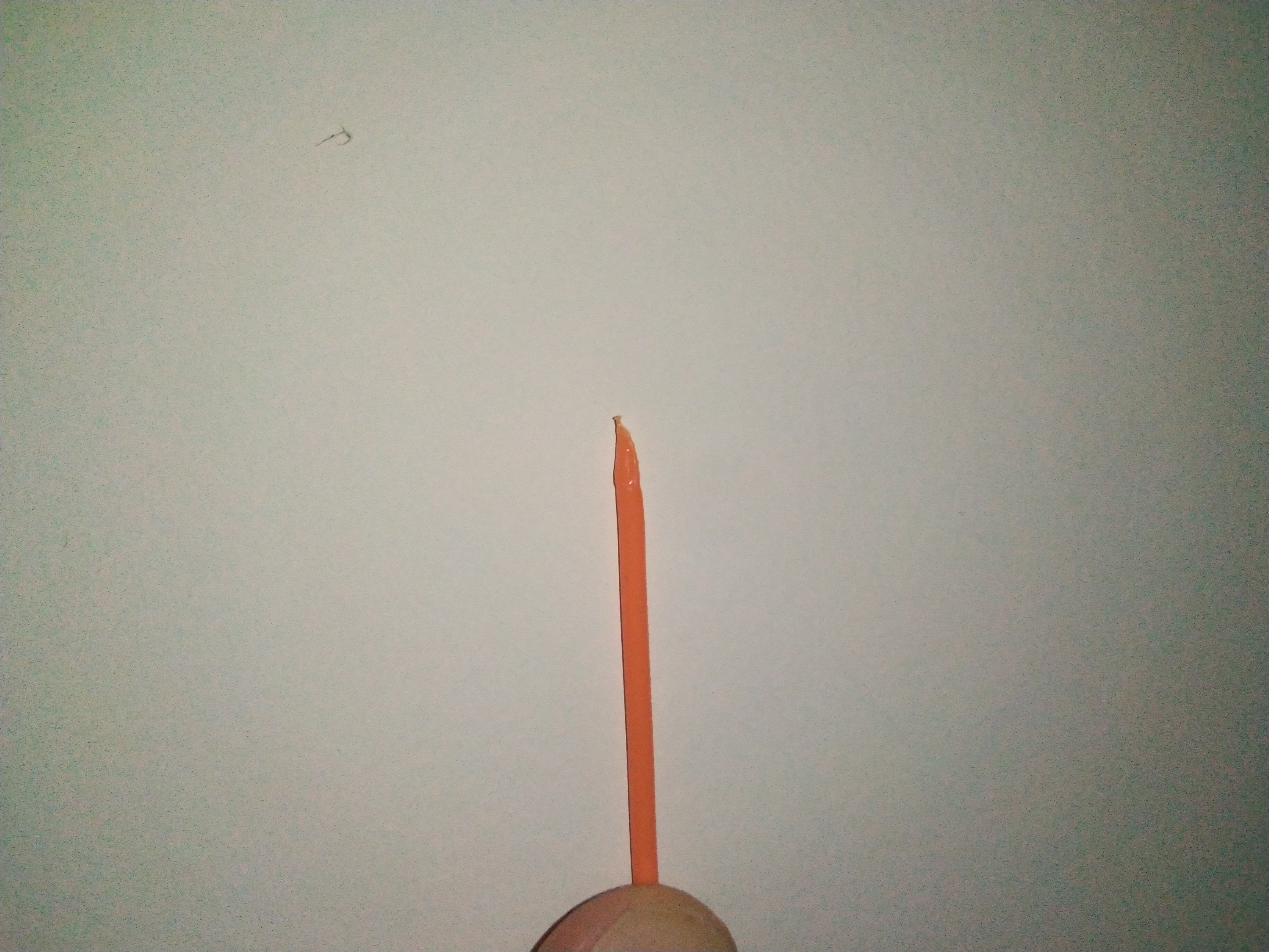
I tried a model with 150filament switch (approach) and work well
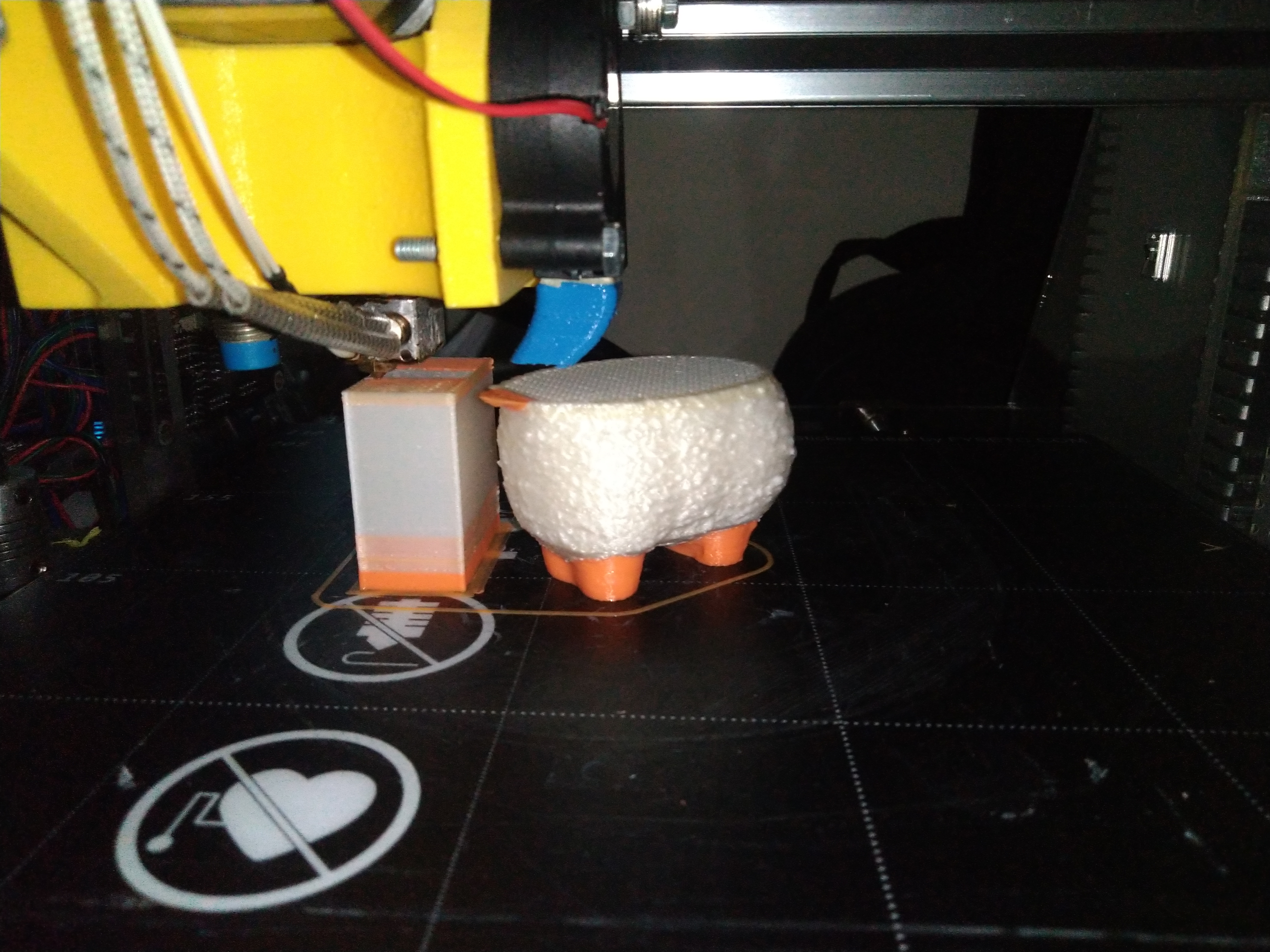
I had some troubles with the tool change on the begining but solve them changing the tool change process on Marlin:
Create a M703 to directly connect with MMU2 without any other mixing codes that allowed me to make a better filament tips.
I use the sequence:
M84 E
M703 U0
T(new_extruder)
So my ramming is made just by the slicer that can improve the tip for each filament kind.
And remove the C0 command from the tool change, this because I don't have the extruder run-out sensor on my printer.
And without this command the MMU2 didn't feed more 38mm than the calibration.
To make a test of changes between different materials with different working temperature, and to be sure that will not have some particles of a high temperature material when I'm purging a low temperature material and strougle the hot end, I made a script to add control temperatures in some zones of the code.
The result:
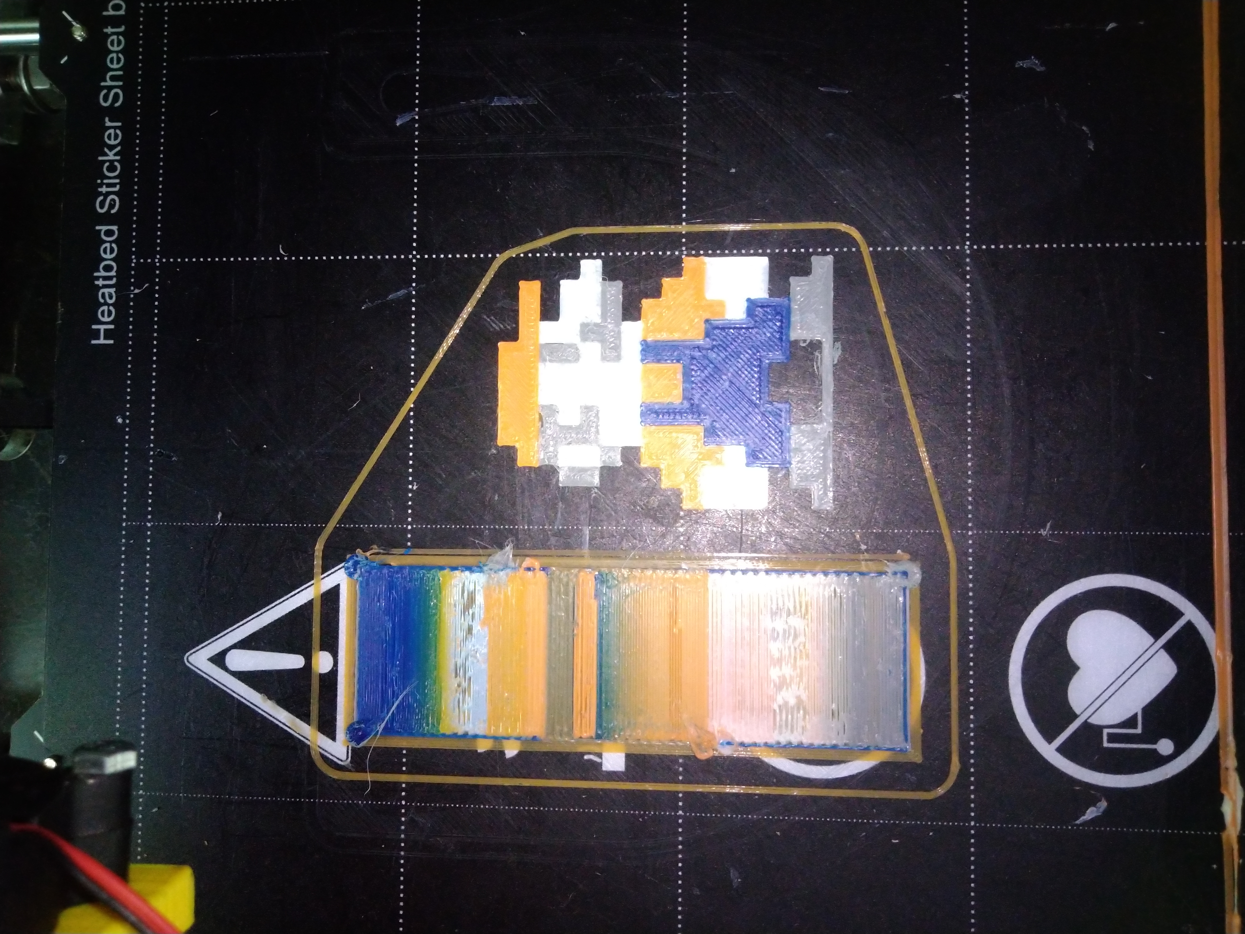
White - PLA
Orange - PLA
Grey - PETG
Blue - ABS
If you want the details of changes, the script or the Prusaslicer profile, ask for it and I'll send them.
FNeo31
on 10 May 2020
@FNeo31 did you make your test with the 2.0.5.3 version of marlin or with my PR?
BastR
on 10 May 2020
@BastR, the main version because I start the tests to much time before your post
FNeo31
on 10 May 2020
@FNeo31
Glad to see yours is working. ive done what i think i need to in order to get mine functioning with my machine. did you need to adjust for a different hotend design?
i had to mess around with unload positions in marlin and prusa slicer for this to work. i have slightly bigger tips due to the fact im using a clone without the special heatbreak.
you mentioned changing tool commands? i haven't touched these is it something i should look into? will be testing a runout sensor design today
0lympu5
on 10 May 2020
@0lympu5
I just need to make the calibration of MMU2 to guarantee that on first load the filament reach the gears like prusa manual.
And I will post here my configs of prusaslicer and the changes on Marlin so you can reproduce like your extruder dimensions. In my case I'm using the extruder that I post here before with e3dv6 heatbreak.
When I go to my PC I'll make a backup of all and post here
FNeo31
on 10 May 2020
@0lympu5
Prusa Slicer Configs:
PrusaSlicer_FNeo_config.ini
Files to change in Marlin:
mmu2.cpp to add M703 functions
mmu2.h to add M703 functions and variables from private to public
gcode.cpp to add M703
gcode.h to add M703
replace M701_M702.cpp for M701_M703.cpp attached
And I think that I didn't forget anything.
So to check I add my Configuration.h and Configuration_adv.h files that you can compare.
My ramming sequence is just on software that its easier to change depending of the material if needed
For adjust distances from your extruder just change the setting indicated in blue on attached image
Some doubt that you have tell and I'll try to help you
My configs are bundle configs so have all
Printer: FNeo Prusa i3 MMU2
Filaments : just are ready the configurations of PLA, PETG and ABS (Filaflex40 and PVA wasn't tested so it's possible that didn't have correct parameters.
Print settings: FNeo Medium (is the best at the moment, I didn't have time to configure and test all of them so use this as base setting for you)
_Attention to script:_
C:\Python38\python.exe C:\PPScriptFNeo.py;
you need to custom install python on C:\ directly to don't have spaces on path, the same for FNeo.py location
FNeo31
on 10 May 2020
I've been using this mmu2 feature for a long time , before it was even merged to master.
I think I just found a recent bad regression though, when I pulled bugfix-2.0.x.
Thanks for the good work.. btw.
The symptom is that after a retry of tool switch the hotend temp is set to 0, which causes the print to stop.
I think I've fixed it as well.
My setup is SKR 1.4 Turbo running Marlin bugfix-2. On the MMU side I have a my own Teensy 4.0 based MMU unit built from scratch that follows the MMU protocol. I have been somewhat frequently getting tool change errors due to Serial communication error for a long time.
I've verified that the Teensy indeed sends the protocol response, but the Marlin & mmu feature never receives it.
This was not a much a problem until now because it recovered and continued printing. I have been using this setup for over a year with this occasional Serial errors.
Here is the pronterface console output if it helps.
MMU <= T1
MMU => 'ok'
echo:Active Extruder: 1
MMU <= T3
MMU retry
MMU not responding
MMU <= T3
MMU => 'ok'
MMU starts responding
Right after that the temp is set to 0 and the print starts to fail with cold extrusion errors.
The changes that made it work is
Remove the
static bool ..., mmu_print_saved;
Change this to accept a stack variable
static void manage_response(const bool move_axes, const bool turn_off_nozzle, bool& mmu_print_saved);
And change all the calls to it.
kursatu
on 12 May 2020
I am considering upgrading from Prusa MK3S Einsy to BTT SKR 1.4 Turbo. My Prusa has an MMU2. Can an MMU2 still be used on a BTT SKR 1.4 board with the LCD screens connected like the TFT3.5 V3.0? These use an extra serial connection compared to a normal LCD. I checked the BTT github for connections of BTT SKR 1.4 and I noticed the WiFi interface also features an independent tx/rx, so if you willing to sacrifice the WiFi connection on the motherboard (which I am), perhaps this port is suitable for a MMU2 serial connection? It seems 3.3V, but maybe the SKR V1.4 also works with 5V serial signal from the MMU2? Are there limitations to a serial port from an MMU2? Is a level shifter board to 5V needed? Anyone has experience with this?
EDIT Biqu support confirmed by mail that it is possible to hook up both TFT and MMU2 to different serial ports of the SKR 1.4 and that the rx/tx pins of the WiFi port (UART3) are 5V tolerant, so no level shifter is needed.
 ruedli
on 15 Jun 2020
ruedli
on 15 Jun 2020
@ruedli I don't know about the SKR 1.4 in particular but for a SKR PRO it works without problems.
However, you should know that Marlin supports the MMU2S thanks to recent PR but this support is not as complete as in the original Prusa firmware, you may lose some features like the cutter, errors counter, resume in case of power failure, etc...
BastR
on 15 Jun 2020
@BastR That is good information, thank you for that. I can live with the more limited options for cutter/powerloss/error counters, but a fully communicating MMU2 - with support for the filament detector in the tower, is important to me.
I checked the schematic on Github for the BTT SKR Pro 1.1. It has both a connection called "TFT" and "UART3" that have different RX/TXs connected to them. UART3 is exposed to a connector called "CONT4". I assume you have your TFT connected to "TFT" and the MMU2 to "CONT4" then?
Unfortunately the SKR 1.4 does not have this extra UART3. The more and more I look into it, I feel the best option is to"abuse" the UART of the WIFI connector, thus eliminating the Wifi option on the mother board, but I would then add the ESP01 to the TFT. Having two ESP's connected would be overkill anyhow. I still wonder if anyone has tried hooking up MMU2 _and_ TFT to an BTT SKR 1.4 board, and how they did it. I also sent a mail to Biqu, I will post their reply here.
EDIT Biqu support confirmed by mail that it is possible to hook up both TFT and MMU2 to different serial ports of the SKR 1.4 and that the rx/tx pins of the WiFi port (UART3) are 5V tolerant, so no level shifter is needed.
ruedli
on 15 Jun 2020
@FNeo31
I put my MMU2 working well with SKR1.3
Curious on how you hooked up the MMU2 to the SKR1.3.
Did you _also_ connect an TFT (using serial connection) to your SKR1.3? The TFT3.5 seem to connect by using _both_ the EXT0/1 and TFT connector, thus "using" on your TFT3.5 what I think you need for connecting the MMU2. Currently I am considering to use the rx/tx signal from the WIFI connector for the MMU2. Is that a good idea?
ruedli
on 15 Jun 2020
You can use the rx/tx that do you want and that is available.
You just need to uncomment the secund serial on configs and configure the serial on MMU2 section
FNeo31
on 15 Jun 2020
Thank @FNeo31 , I ordered an SKR 1.4 and will try to hook up the MMU2S to the WiFi port. This is UART3, which I need to configure in the MMU2 section. Biqu also replied and confirmed that also these pins are 5V tolerant, so no level shifter is needed.
ruedli
on 16 Jun 2020
Set "Serial3" on MMU2 section instead of internal_serial.
If you want, later I can post the example
FNeo31
on 16 Jun 2020
Set "Serial3" on MMU2 section instead of internal_serial.
If you want, later I can post the example
Yes, that makes sense. Should I also enable Serial3 in the HAL? These pins are multipurpose, could also be timers e.g.
ruedli
on 16 Jun 2020
I think it's not necessary, try first
FNeo31
on 16 Jun 2020
Yes, will try, but I need to wait till the board arrives, I just ordered them.
ruedli
on 16 Jun 2020
Set "Serial3" on MMU2 section instead of internal_serial.
If you want, later I can post the example
Have you got this working? I have enabled Serial3 on my SKR 1.4 Turbo as trying to use the WiFi port but the MMU2 doesn't respond to it at all eventually saying:
MMU not responding - DISABLED
Tried a few things in the config currently set to:
//#define INTERNAL_SERIAL_PORT 3
#define MMU2_SERIAL Serial3
As well as a few other things but that is what is currently there, checked pin out and think it was correct to start but have tried swapping the RX/TX around just in case but it made no difference.
 james194zt
on 3 Aug 2020
james194zt
on 3 Aug 2020
@james194zt
Yes it's working, I had the same trouble is a case of reset sequence. If you want I send you all configs. For MMU2, Marlin and slicer if you want
FNeo31
on 3 Aug 2020
@james194zt
Yes it's working, I had the same trouble is a case of reset sequence. If you want I send you all configs. For MMU2, Marlin and slicer if you want
Yes please ,that would be amazing, I would love to see a working config of it
james194zt
on 3 Aug 2020
@james194zt
When I arrive at home from work today I'll post here a link to download all and a readme file to explain all
FNeo31
on 3 Aug 2020
@james194zt wifi port is not Serial 3 by default, unless you hack the framework. see https://youtu.be/NGgzw-XayEo?t=1502 for how to change your lpc1768 framework and set the wifi pins up as Serial 3
 ellensp
on 3 Aug 2020
ellensp
on 3 Aug 2020
@james194zt wifi port is not Serial 3 by default, unless you hack the framework. see https://youtu.be/NGgzw-XayEo?t=1502 for how to change your lpc1768 framework and set the wifi pins up as Serial 3
Doh, I skimmed over that video yesterday thinking it would be the clue to the problem, I missed that part as had seen nothing I hadn't done!
james194zt
on 3 Aug 2020
@james194zt
When I arrive at home from work today I'll post here a link to download all and a readme file to explain all
Great thanks. I got serial established but would still love to see a working config of it.
james194zt
on 3 Aug 2020
@james194zt
Like I said attached all configs and ReadMe file explaining everything
(If I didn't forget nothing, if I forget, ask what you need :) - and this ReadMe it's really to read xD )
At the moment is uploading so maybe 15-25 min and I think that all files will be available
https://drive.google.com/drive/folders/17SP11Ato4_yCU67k6JUW_ae6bsmJDjqE?usp=sharing
FNeo31
on 3 Aug 2020
I am away from home, but hopefully will be able to try it in two weeks. First I compiled a dev version of Marlin, but I noticed that MMU2S support was also merged in in 2.06, so now I am on that tag. It compiled fine.
ruedli
on 4 Aug 2020
@FNeo31 and @james194zt
I had a quick look at the config files in https://drive.google.com/drive/folders/17SP11Ato4_yCU67k6JUW_ae6bsmJDjqE?usp=sharing
Whereas they should work, it could be that they are not optimal.
To recap: There are three modes in which the MMU2 can work:
- As it worked when initially released by Prusa: then it relies on calibration of the 5 filament path lengths: MMU2 "old mode"
Using a standard filament sensor, then it works slightly better, it will detect close to the extruder and then load the remaining part. MMU2 "improved mode", this is also brought into Marlin.
With the sensor attached to the filament door, as in "MMU2S mode". Then it will detect when the door moves and when the filament is really close the the extruder gear (and therefore be even more reliable for loading filament).
In order to work in MMU2S mode, you need to be on Marlin 2.06 or newer, that release brought:
- Prusa MMU2 Extruder Sensor support
- Add settings for Prusa MMU2S
As far as I can see, your config files are for a 2.05 release? More in particular, they miss the section PRUSA_MMU2_S_MODE, which comes right after section PRUSA_MMU2 in Configuration_adv.h, like here:
/**
   * Using a sensor like the MMU2S
   * This mode requires a MK3S extruder with a sensor at the extruder idler, like the MMU2S.
   * See https://help.prusa3d.com/en/guide/3b-mk3s-mk2-5s-extruder-upgrade_41560, step 11
   */
  //#define PRUSA_MMU2_S_MODE
  #if ENABLED(PRUSA_MMU2_S_MODE)
    #define MMU2_C0_RETRY   5             // Number of retries (total time = timeout*retries)

etc.....
Note that you must upgrade your MK3 extruder, to become an MK3S extruder with an MMU2S sensor working on the extruder door: so this is different from the "normal" MK3S optical switch sensor. It is the same hardware, but different "plastic", no steel roller ball e.g.
All three modes need a working serial UART to the MK3 board. Chris is explaining how he enabled that for serial communication (GCODE commands), this would be for the touch panel interface. You need to follow his advice on how to correctly define the pins for Serial3, but then use this UART for the MMU2, and not for receiving GCODE commands. My goal is to set that up for using Serial3 of the Wifi bus, and still use Serial1 for the touch panel (accepting normal GCODE cmmands). The Serial1 is what most people (probably) use for hooking up the MMU2, and this is where I want to deviate, in favor of the BTT TFT3.5 v3 touch panel.
Hope this helps, unfortunately I will not be close to my printer the coming weeks, so I cannot try out anything.... If you have it working under 2.05: probably all you want is to go to Marlin 2.06 and get the hardware upgrade working as reliable as under the current Prusa release: In MMU2S mode.
ruedli
on 4 Aug 2020
@ruedli
Like I put on readme file, this is a old version of Marlin because I didn't have time to test the 2.0.6.
The version is 2.0.5 from bugfix so from March I think, but with some changes made by me, because without the changes I had a lot of troubles on filament change
FNeo31
on 4 Aug 2020
@FNeo31 I see, thanks for your feedback. I waited for the feature on the MMU2S,
because I already had my Prusa hardware (chimney-type filament detector
based on IR sensor) in that configuration. I tried a MARLIN dev version
first, but now that the stable 2.06 is released 8 days ago - with the MMU2S
support - I will go for that. For other users hooking op the MMU2, they
should make a decision whether or not they want MMU2S support. If that is
the case, working from 2.06 or newer is in my opinion the best approach,
which is why I commented.
Your feedback on the Serial is very helpful! MMU2 / MMU2S are not any
different with respect to configuring the serial port, so it is good to
see, you got that working.
Op di 4 aug. 2020 om 20:32 schreef FNeo31 notifications@github.com:
@ruedli https://github.com/ruedli
Like I put on readme file, this is a old version of Marlin because I
didn't have time to test the 2.0.6.
The version is 2.0.5 from bugfix so from March I think, but with some
changes made by me, because without the changes I had a lot of troubles on
filament change—
You are receiving this because you were mentioned.
Reply to this email directly, view it on GitHub
https://github.com/MarlinFirmware/Marlin/issues/11859#issuecomment-668756822,
or unsubscribe
https://github.com/notifications/unsubscribe-auth/ABGGYOH25FJ4TIUNR2SL3F3R7BH27ANCNFSM4FVTMKPQ
.
--
Ruud Rademaker
prefered mail: ruud.[email protected]
ruedli
on 4 Aug 2020
This issue has been automatically locked since there has not been any recent activity after it was closed. Please open a new issue for related bugs.
![github-actions[bot] picture](https://avatars2.githubusercontent.com/in/15368?v=4&s=40) github-actions[bot]
on 4 Oct 2020
github-actions[bot]
on 4 Oct 2020
Related issues
 esenapaj
·
3Comments
esenapaj
·
3Comments
 otisczech
·
3Comments
otisczech
·
3Comments
 Kaibob2
·
4Comments
Kaibob2
·
4Comments
 ahsnuet09
·
3Comments
ahsnuet09
·
3Comments
 Glod76
·
3Comments
Glod76
·
3Comments
Most helpful comment
I walked through the Prusa sources already. Nothing too complex, but we'll have to generalize, implement the serial communication based on the HAL, etc. to make the MMU usable with as many printers as possible.