Marlin: extruder stop working after update to 1.1.9 with TMC2130
Description
I was using Marlin 1.1.8 with TMC2130 without any issue (some layer shift, but this is another case)..
After I upgrade to Marlin 1.1.9, the extruder don't work anymore.
My board it's a Arduino Mega 2560 with RAMPS.
In Marlin 1.1.8, on Configuration_adv.h, I have the following config:
#define HAVE_TMC2130
...
#define X_IS_TMC2130
#define Y_IS_TMC2130
#define Z_IS_TMC2130
#define E0_IS_TMC2130
In Marlin 1.1.9, In Configuration.h:
#define X_DRIVER_TYPE  TMC2130
#define Y_DRIVER_TYPE  TMC2130
#define Z_DRIVER_TYPE  TMC2130
#define X2_DRIVER_TYPE A4988
#define Y2_DRIVER_TYPE A4988
#define Z2_DRIVER_TYPE A4988
#define E0_DRIVER_TYPE TMC2130
#define E1_DRIVER_TYPE A4988
#define E2_DRIVER_TYPE A4988
#define E3_DRIVER_TYPE A4988
#define E4_DRIVER_TYPE A4988
I'm using TMC2130 with SPI mode (not the software SPI)
The CS pins are the same than Marlin 1.1.8, but when use the M122 command, the E0 driver don't show on report:
    X   Y   Z
Enabled     false   false   false
Set current 1000    1000    1000
RMS current 994 994 994
MAX current 1402    1402    1402
Run current 17/31   17/31   17/31
Hold current    8/31    8/31    8/31
CS actual       8/31    8/31    8/31
PWM scale       46  45  40
vsense      0=.325  0=.325  0=.325
stealthChop false   false   false
msteps      16  16  16
tstep       1048575 1048575 1048575
pwm
threshold       0   0   0
[mm/s]      -   -   -
OT prewarn  false   false   false
OT prewarn has
been triggered  false   false   false
off time        5   5   5
blank time  24  24  24
hysteresis
-end        2   2   2
-start      3   3   3
Stallguard thrs 0   0   0
DRVSTATUS   X   Y   Z
stallguard      X   X   X
sg_result       35  118 113
fsactive
stst        X   X   X
olb     X   X   X
ola     X   X   X
s2gb
s2ga
otpw
ot
Driver registers:   X = 0xE1:08:00:23
    Y = 0xE1:08:00:76
    Z = 0xE1:08:00:71
Steps to Reproduce
Update the Marlin FW from 1.1.8 to 1.1.9 (with TMC2130 driver)
Expected behavior: Extruder work! :P
Actual behavior: Extruder don't work! the console show no error.
 tobecwb
All 17 comments
Appears to be a hardware problem... I really don't know
In Marlin 1.1.8, the STEALTHCHOP was enabled.
On Marlin 1.1.9, I leave disabled (I read on some place that this can cause layer shifting...)
So, I downgrade the firmware to Marlin 1.1.8, and disabled the STEALTHCHOP.
Extruder show on M122 command, but don't works. So, I enabled the STEALTHCHOP again, and everything works.
Then, I upgrade again to Marlin 1.1.9, but this time, I enabled the STEALTHCHOP option, and now the extruder works (but don't appear on M122 command).
To be sure, I swap the TMC2130 from Z and E, and with STEALTHCHOP disabled, the Z axis stop working.
tobecwb
on 6 Aug 2018
Try the bugfix branch.
 teemuatlut
on 6 Aug 2018
teemuatlut
on 6 Aug 2018
I have exactly the same problem with my TMC2130 and RAMPS 1.4.
Using release 1.1.8 with and without stealthchop / hybrid threshold (doesn't matter) there is no problem detecting the drivers:
    X   Y   Z   E0
Enabled     false   false   false   false
Set current 650 650 650 650
RMS current 646 646 646 646
MAX current 911 911 911 911
Run current 12/31   12/31   12/31   12/31
Hold current    6/31    6/31    6/31    6/31
CS actual       6/31    6/31    6/31    6/31
PWM scale   0   0   0   0
vsense      1=.18   1=.18   1=.18   1=.18
stealthChop false   false   false   false
msteps      16  16  16  16
tstep       1048575 1048575 1048575 1048575
pwm
threshold       0   0   0   0
[mm/s]      -   -   -   -
OT prewarn  false   false   false   false
OT prewarn has
been triggered  false   false   false   false
off time        5   5   5   5
blank time  24  24  24  24
hysteresis
-end        2   2   2   2
-start      3   3   3   3
Stallguard thrs 0   0   0   0
DRVSTATUS   X   Y   Z   E0
stallguard      X   X   X
sg_result       791 868 339 0
fsactive
stst        X   X   X   X
olb             X   X
ola                 X
s2gb
s2ga
otpw
ot
Driver registers:   X = 0x81:06:03:17
    Y = 0x81:06:03:64
    Z = 0xC1:06:01:53
    E0 = 0xE0:06:00:00


ok
I updated to release 1.1.9 and my E0 is not working:
        X   Y   Z
Enabled     false   false   false
Set current 600 600 800
RMS current 596 596 795
MAX current 840 840 1121
Run current 11/31   11/31   15/31
Hold current    5/31    5/31    7/31
CS actual       5/31    5/31    7/31
PWM scale       4   4   4
vsense      1=.18   1=.18   1=.18
stealthChop false   false   false
msteps      16  16  16
tstep       1048575 1048575 1048575
pwm
threshold       0   0   0
[mm/s]      -   -   -
OT prewarn  false   false   false
OT prewarn has
been triggered  false   false   false
off time        5   5   5
blank time  24  24  24
hysteresis
-end        2   2   2
-start      3   3   3
Stallguard thrs 0   0   0
DRVSTATUS   X   Y   Z
stallguard
sg_result       0   0   0
fsactive
stst        X   X   X
olb     X   X   X
ola     X   X   X
s2gb
s2ga
otpw
ot
Driver registers:   X = 0xE0:05:00:00
    Y = 0xE0:05:00:00
    Z = 0xE0:07:00:00


ok
Since I'm using the same SPI pin for the TMC's as for my SD Card I tried half speed and I also disabled the whole SD feature. My E0 is not showing up in any combination I have tried. I also tried turning on and off stealthchop with an without hybrid threshold - nothing worked out.
After flashing back to 1.1.8 everything was registred fine without problems and working SD card as expected - because it was working before. So there is definitely not a hardware problem with my printer.
Something must have changed which is now causing problems scanning the SPI BUS for the TMC's?
 Decstasy
on 6 Aug 2018
Decstasy
on 6 Aug 2018
@teemuatlut tried the bugfix branch. same result. This branch appears to have some new option for X dual carriage only and some updates for graphic display. Nothing related with TMC or stepper motor drivers.
I will check the hardware again.
tobecwb
on 7 Aug 2018
Checked again the driver for Z axis.
I got a TMC2130 v1.1 from BIGTREETECH, in standalone mode, and this stepper is hard to set in SPI mode. Must remove a resistor, and solder two small solder points.
Removed all solder points, and made again the SPI mode connection. This time, the driver worked on Z axis. So, appears to be a hardware problem. Everything is working again, with and without STEALTHCHOP (tested on 1.1.8 and 1.1.9).
Appears that the TMC2130 was responding to M122, but ignoring others commands... I really don't know.
But, in Marlin 1.1.9, the M122 command don't report the E0 address or any other info (but it's working). This is a "feature" of version 1.1.9?
For me, this issue can be closed, but @Decstasy has similar problem too.
@Decstasy , I'm using the same SPI pins for TMCs and SD, so I don't think this is your problem.
tobecwb
on 7 Aug 2018
There were updates to the driver macros in 1.1.9 and it introduced some problems. This is partly fixed in bugfix-1.1.x but I think we can do better.
You can try a branch from my repo if that works better for you.
https://github.com/teemuatlut/Marlin/tree/bf1_fix_smart_drivers
teemuatlut
on 7 Aug 2018
I have used the 1.1.x repository branch with the newest commits and made my whole configuration new from scratch. So I was not using git stash to merge my existing configuration with it...
It's now working fine but I have still no idea what caused this problem. On request I would take the configuration to the 1.1.9 release and try it again - I mean there must be a diffference.
So overall the issue is also solved for me.
Decstasy
on 8 Aug 2018
But, in Marlin 1.1.9, the
M122command don't report the E0 address or any other info (but it's working). This is a "feature" of version 1.1.9?
AFAIK. It should be doing what we intended.
 thinkyhead
on 13 Aug 2018
thinkyhead
on 13 Aug 2018
Checked again the driver for Z axis.
I got a TMC2130 v1.1 from BIGTREETECH, in standalone mode, and this stepper is hard to set in SPI mode. Must remove a resistor, and solder two small solder points.Removed all solder points, and made again the SPI mode connection. This time, the driver worked on Z axis. So, appears to be a hardware problem. Everything is working again, with and without
STEALTHCHOP(tested on 1.1.8 and 1.1.9).Appears that the TMC2130 was responding to
M122, but ignoring others commands... I really don't know.But, in Marlin 1.1.9, the
M122command don't report the E0 address or any other info (but it's working). This is a "feature" of version 1.1.9?For me, this issue can be closed, but @Decstasy has similar problem too.
@Decstasy , I'm using the same SPI pins for TMCs and SD, so I don't think this is your problem.
Hi @tobecwb, I have the same TMC2130 v1.1 from BIGTREETECH and I cannot get them working. I get Driver registers: X = 0xFF:FF:FF:FF on all 4 drivers. Checking the CFG4 and CFG5 board jumpers seems to be wrong. Any clue about your SPI solder points could help me a lot because im crazy with this chips.
This is I think about it:

My TMC2130 is the real fotage which seems to be wrong and the right connection I found somewhere.
Thanks you
 moracabanas
on 4 Nov 2018
moracabanas
on 4 Nov 2018
@moracabanas , don't forget that you need remove the resistor (R5).
I used the following diagram on my TMC 2130 v1.1
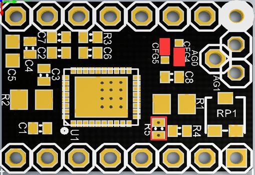
The solder pad it's very hard to solder! I had to use a small piece of wire to make the jumper!
The resistor is easy to remove, but it is almost certain that it will be damaged during removal
tobecwb
on 4 Nov 2018
So mine comes with that path soldered and no R5 resistor but no valid adress on SPI. I am using Re-Arm and I found the correct HW SPI for that board but not working at all. Im lost :(
moracabanas
on 5 Nov 2018
@moracabanas I can't get my brand-new TMC2130 v1.1 from BIGTREETECH working either. I have some FYSETC TMC2130 v1.1 drivers and they work fine (in the same board with the same wiring). I can only conclude that these BIGTREETECH drivers are just plain broken. They're literally supposed to be the same board/pinout as the FYSETC ones (drop-in replacement) yet they do not work when dropping them in. The FYSETC ones work but not these BIGTREETECH ones.
I had a detailed look at the soldering job on the board and I can't find anything amiss. They look fine but when plugging them in they do not work--at all.
 liftoff
on 8 Nov 2018
liftoff
on 8 Nov 2018
this is strange!
i got 4 TMC2130 v1.1 from BIGTREETECH, all working in SPI mode after remade the soldering (remove resistor, and short the cfg4 and cfg5 with a thin wire)!
the first and second time this don't worked! but on third attempt, everything is working correctly.
tobecwb
on 8 Nov 2018
Nevermind: It's a unique thing with the BIGTREETECH boards and the MKS Gen-L: You have to remove the jumpers underneath the drivers because the pins on the BIGTREETECH boards extend down as well as up.
The BIGTREETECH boards that I got have the SPI pins extended up from the board (normal) but also extending down into the stepper driver headers (not normal). Pulling out those little jumpers fixed the issue.
Of course, there's ZERO documentation for any of this. The MKS Gen style boards are great but man they suck in the realm of documentation.
liftoff
on 8 Nov 2018
The BIGTREETECH boards that I got have the SPI pins extended up from the board (normal) but also extending down into the stepper driver headers (not normal).
It's unfortunate that they didn't document that better and that it caused you trouble. As annoying as it must have been in your case I'm thinking extending the pins both ways might be a nice feature.
Mine are "normal" extending only up meaning there are fewer pins holding the board into it's socket. Also, I have protector boards that plug into my RAMPS board in place of the stepper controllers and the controllers plug into those. They protect the Trinamic chips from various sources of power surges that might otherwise damage them.
Anyway, between being elevated so far off the board and having fewer pins holding them in I find it is easy to get one of the many wires to push against one and pop it part way out of it's socket. Maybe your BIGTREE boards with more pins to hold them in would be more resistant to this!
 kc8rwr
on 26 Jan 2019
kc8rwr
on 26 Jan 2019
Nevermind: It's a unique thing with the BIGTREETECH boards and the MKS Gen-L: You have to remove the jumpers underneath the drivers _because the pins on the BIGTREETECH boards extend down as well as up_.
Removing the three jumpers isolates the pins MS1(SDI) , MS2(SCK) and MS3(CS), but not the pin /RST(SDO).
Did you cut off the downward pin of /RST(SDO)? Probably the safe way is to cut at least that pin.
I didn't find a schematic how the /RST pin is wired to my GT2560 Rev A+ board. Measuring the unpowered board revealed that it is probably connected to a transistor (or an I/O pin) but the /RST pins of the sockets are not directly connected to each other.
/EDIT: In the meanwhile I found out, that /RST is connected to /SLP of the same socket on the GT2560 board and that pin is marked as "nc" on the BIGTREETECH board.
Michael
 nospam2000
on 10 Apr 2019
nospam2000
on 10 Apr 2019
This issue has been automatically locked since there has not been any recent activity after it was closed. Please open a new issue for related bugs.
![github-actions[bot] picture](https://avatars2.githubusercontent.com/in/15368?v=4&s=40) github-actions[bot]
on 13 Jul 2020
github-actions[bot]
on 13 Jul 2020
Related issues
 modem7
·
3Comments
modem7
·
3Comments
 ceturan
·
4Comments
ceturan
·
4Comments
 heming3501
·
4Comments
heming3501
·
4Comments
 pubalan12
·
4Comments
pubalan12
·
4Comments
 Kaibob2
·
4Comments
Kaibob2
·
4Comments
Most helpful comment
Nevermind: It's a unique thing with the BIGTREETECH boards and the MKS Gen-L: You have to remove the jumpers underneath the drivers because the pins on the BIGTREETECH boards extend down as well as up.
The BIGTREETECH boards that I got have the SPI pins extended up from the board (normal) but also extending down into the stepper driver headers (not normal). Pulling out those little jumpers fixed the issue.
Of course, there's ZERO documentation for any of this. The MKS Gen style boards are great but man they suck in the realm of documentation.