Marlin: Pauses in K factor test pattern - read ahead issue?
When I am printing the k-factor test pattern, the hotend slows right down/comes to a complete stop after the initial slow segment - I would have expected the planner to have detected the change of speed is moving in the same direction and not slowed down/or stopped towards the end of the slow segment? Because of this I am seeing blobs at the start of the fast segment even with K=0.
I don't think I have configured anything that would have messed with the read-ahead like this, but I'm
not 100% sure,and I don't know where to look.
Happens both from USB and SD card.
here is my config:
https://github.com/Squid116/Marlin/blob/bugfix-1.1.x/Marlin/Configuration.h
and config_adv:
https://github.com/Squid116/Marlin/blob/bugfix-1.1.x/Marlin/Configuration_adv.h
(Edit: updated links to correct branch in my github repo)
 Squid116
All 172 comments
Here is a quick video showing the pause:
https://youtu.be/wWB5UVfcHV8
Squid116
on 8 Apr 2018
What is your Z Jerk set to? Try increasing it to see if it helps.
 thinkyhead
on 8 Apr 2018
thinkyhead
on 8 Apr 2018
Z zerk @tinkyhead? Sure you don't mean E jerk?
Squid116
on 8 Apr 2018
No, I mean Z Jerk.
thinkyhead
on 8 Apr 2018
But it isn't moving in z at all? I have the same results with ubl disabled.
Squid116
on 8 Apr 2018
That answers my question, then. In some instances having too small a Z jerk interacts with bed leveling to create unwanted pauses. If I think of anything else for you to try, I'll let you know.
thinkyhead
on 8 Apr 2018
I'll try the jerk anyway and see, but unless G29 D isn't working, I doubt it.
Could it be related to my lowish acceleration values? It should be reaching speed in those distances...not that I'm sure that matters.
Squid116
on 8 Apr 2018
There should be no pauses in the middle of single linear moves. Would you mind attaching the G-code you're using so we can make sure it has no weird issues? (May need to ZIP it first.)
thinkyhead
on 8 Apr 2018
@tinkyhead, already Attached to first post. Kfactor (16).gcode.txt
Squid116
on 8 Apr 2018
I have a re-arm sitting on the shelf, waiting for the right time to pull it out, could this be that time?
Squid116
on 8 Apr 2018
Used the same file but removed the G29, and manually did a G29 D beforehand, same result.
Squid116
on 8 Apr 2018
@Sebastianv650 — How does E jerk affect the behavior of the K-factor test? Can it lead to pauses as the extrusion amount changes in that test?
thinkyhead
on 8 Apr 2018
I can try upping the E jerk in the morning, and see how it goes. What is a sensible value? Titan extruder (3:1), 16 microsteps, 837 steps/mm
Squid116
on 8 Apr 2018
If the exactly same thing happens with K=0 we can rule out E jerk. Also the low acceleration shouldn't hurt, if any it should help for the print. My first intention watching the video was also in the bed leveling direction. Can we say for sure that Marlin with UBL enabled but without G29 behaves like Marlin built without UBL? Never played with UBL, so it's maybe a dumb question..
If we can rule out UBL, I will load the latest bugfix to my printer and check if I can see something strange during the pattern.
How does E jerk affect the behavior of the K-factor test? Can it lead to pauses as the extrusion amount changes in that test?
E jerk can slow down the used acceleration for the print move, but it will never alter entry or exit speeds.
What is a sensible value? Titan extruder (3:1), 16 microsteps, 837 steps/mm
I don't know, but if you find one let us know as I will convert my printer to a Titan as soon as my 3mm filament is eaten away :)
 Sebastianv650
on 8 Apr 2018
Sebastianv650
on 8 Apr 2018
This morning I tried:
Changing to bilinear
Changing to no levelling
Doubling jerk
All with no noticeable difference to the result. I'm going to try the alternate pattern to see if the problem is only with the first segment.
Squid116
on 8 Apr 2018
Just tried the alternate pattern and the pauses still seem to be there on the acceleration phases, although the blobbing seems to be less.
Is there a way to check the entry and exit speeds?
Squid116
on 8 Apr 2018
Just tried with //#define LIN_ADVANCE commented out and same behavior.
Also tried increasing the length of the slow segments, no dice.
Squid116
on 9 Apr 2018
Changed the slow print speed to 10 - Bingo! It worked, no pause, could see a nice starvation at the start of fast segment.
Same result at 15, but a pause for 20 and higher (also test 50).
Just a thought that it might be pausing at 10 & 15, but the deceleration phase is fast enough that I cant see it/it isn't notable, but it definitely produces the result id expect from a LA test (with LA disabled) which the faster speeds don't.
Squid116
on 9 Apr 2018
Good to know it's LA independent. I should be able to do some tests this evening.
First thing to check is if the problem persists if there is no E movement..
Is there a way to check the entry and exit speeds?
Nothing you can enable by sending an M code or so, but you can insert some serial echo lines inside the planner and/or the trapezoid_generator_reset function which is called once on every new executed block. But it will slow down the execution speed so it's only useful to test specific short gcodes like this slow-fast-slow combination.
Sebastianv650
on 9 Apr 2018
I can confirm this behavior as well, at first I thought it was because I enabled Bezier_Jerk_Control but upon disabling the issue remained. Also using UBL for whatever that's worth.
 jokeman3000
on 9 Apr 2018
jokeman3000
on 9 Apr 2018
I can reproduce the issue even with X axis only moves. I guess it wasn't noticed until now because it's only noticeable with very low acceleration values. With a=100mm/s² it's obvious, with 1000 it's not visible.
Let's see what's the reason behind it!
Sebastianv650
on 9 Apr 2018
The jerk limiting code inside the planner is limiting the junction speed between slow-fast moves to the axis jerk speed. During the fast-slow transition, no limit is applied so
vmax_junction = min(block->nominal_speed, previous_nominal_speed);
is used as junction speed.
I don't understand the meaning of the smaller_speed_factorinvolved in v_exitcalculation, but I guess that might be the crucial point.
@thinkyhead do you understand this section of the jerk code? I compared it with Prusa FW and its behaviour is identical, so it's no fault which occurred after its porting to Marlin.
Sebastianv650
on 9 Apr 2018
I'm not sure if the current way of calculating "jerk" is doing what we want at all:
- If we define jerk as a speed change per axis as we do it at the moment, the observed behaviour (stop between slow-fast) is true: The speed change on X is 70-20 = 50mm/s for example. 50mm/s > jerk (say 5mm/s) so the printer has to slow down to 5mm/s during the junction.
-> In this case, the issue is in fact the not used jerk speed during the fast-slow transition! - Logically, we want the junction speed in this example to be 20mm/s (=speed of slow section) in both slow-fast and fast-slow transitions as it results in 0 jerk due to acceleration regardless of the used speeds for fast and slow part..
- Again "logically" jerk means an amount of speed change due to a direction change. We can't detect direction changes by comparing each axis independetly from each other as the current code does.
All the madness is visible if you let Marlin travel along a regular poligon like an octagon at constant speed. Each cornering happens by the same angle, so I would expect the same junction speed due to jerk at each corner.
I used a nonagon for this part, circling it twice, here is the result showing the junction speeds:
Gcode:
G91
G1 F4200
G1 X7.019 Y-19.284
G1 X17.772 Y-10.261
G1 X20.209 Y3.563
G1 X13.191 Y15.72
G1 Y20.521
G1 X-13.191 Y15.72
G1 X-20.209 Y3.563
G1 X-17.772 Y-10.261
G1 X-7.019 Y-19.284
; second loop
G1 X7.019 Y-19.284
G1 X17.772 Y-10.261
G1 X20.209 Y3.563
G1 X13.191 Y15.72
G1 Y20.521
G1 X-13.191 Y15.72
G1 X-20.209 Y3.563
G1 X-17.772 Y-10.261
G1 X-7.019 Y-19.284
Junction speeds:
4.00 (start = jerk speed)
7.64
8.00
6.75
6.22
6.22
6.75
8.00
7.64
11.69
7.64
8.00
6.75
6.22
6.22
6.75
8.00
7.64
If we want to stay with the per-axis code (think about deltas, Core and others) we have to understand how to fix the special case "same direction - increased speed". And make a decission which behaviour is the wanted one.
Sebastianv650
on 9 Apr 2018
@Sebastianv650 Thanks for that investigation - I thought I was going mad, but good to see it isn't just me...
Squid116
on 10 Apr 2018
My initial reaction is, "Dammit, are we ever going to fix the bloody jerk code? We've been over this a million times, and there's no end to the problems."
I would recommend we take whatever Grbl is currently doing and completely replace our broken jerk implementation, assuming it's not just as bad.
thinkyhead
on 10 Apr 2018
In fact the grbl planner looks incredible lean, so it's always worth a look anyway. Only regarding the trapezoid realtime-calculation and step execution I'm not sure if this can be transfered to Marlin. And the planner is not written for deltas.
I can't invest the time for a planner port at the moment, but just mention my name if there are questions if someone starts it. I spent some time last winter for initial thoughts for planner changes, so maybe I can help in some cases.
And of course it's always fun for me to test and analyze the behaviour of a planner like I did above :)
Sebastianv650
on 10 Apr 2018
// Calculate jerk depending on whether the axis is coasting in the same direction or reversing.
const float jerk = (v_exit > v_entry)
    ? //                                  coasting             axis reversal
      ( (v_entry > 0 || v_exit < 0) ? (v_exit - v_entry) : max(v_exit, -v_entry) )
    : // v_exit <= v_entry                coasting             axis reversal
      ( (v_entry < 0 || v_exit > 0) ? (v_entry - v_exit) : max(-v_exit, v_entry) );
Following on from what @Sebastianv650 suggested, I think this code is the root of the problem - I think coasting vs reversal is the wrong concept to apply here.
At the end of the day we are either accelerating, decelerating or maintaining.
- If accelerating or maintaining on a given axis
- no changes to the junction speed should be made.
- If decelerating on an axis:
- the junction speed should be restricted so the axis doesn't exceed v_entry+max_jerk[axis], which will allow v_entry to be hit instantaneously.
- if the deceleration is also a reversal (I'm not sure youd need to specifically check this) the junction should speed not exceed max(v_entry+max_jerk[axis], 0)
Squid116
on 11 Apr 2018
What do you mean with:
no changes to the junction speed should be made.
This code section defines the max. possible jerk at the junction (=not always the executed one). We need a max. value to operate with.
Your second point is also quite confusing to me. Why you want to add max jerk to the entry speed? If the entry speed is 70mm/s and maxjerk is 10 (both along one axis), I'm quite sure you don't want an executed jerk of 80mm/s. I don't know any printer which could handle this value ;)
Sebastianv650
on 11 Apr 2018
Likewise v_factor should be calculated as the ratio of v_entry to the calculated VMAX for the axis.
I can't see the ratio of speed change vs max jerk it currently uses as having any meaningful value.
Squid116
on 11 Apr 2018
@sebastianv650
When accelerating (the 20->70 junction) there should be no jerk limiting, it should stay at the previous nominal until it hits the junction.
The second point only applies to deceleration - (i.e. the 70 -> 20 junction) then the junction speed should be v_entry + jerk (i.e. 20 plus the max jerk). That way it can instantaneously hit v_entry when it enters the segment.
Squid116
on 11 Apr 2018
The second point only applies to deceleration - (i.e. the 70 -> 20 junction) then the junction speed should be v_entry + jerk (i.e. 20 plus the max jerk). That way it can instantaneously hit v_entry when it enters the segment.
No, we always want smooth speeds. Jerk is not used to jump speeds between segments, it's used to limit the force due to a mass changing direction onto the printers structure. In this example with a fast 70 and a slow 20mm/s line, we want to cruise at 70mm/s until a distance before the segment end where we have to start decelerating at given print acceleration setting so we reach 20mm/s just at the segments end. The 20mm/s segment starts at 20mm/s, cruises at 20mm/s and starts decelerating to 0 at a point before its end so we reach 0mm/s (minimum_planner_speed in real live) at each end.
In this slow-fast-slow one-axis example, there is no jerk at all which could (or should) be handled by the jerk speed control. There is no jerk between two paths along the same direction.
Jerk comes into play when we angle the second (for example slow) segment 45° around Z-axis so we make a X axis only move first, continued by a XY-axis move at the same or different speed. While the junction speed along the travel path might be still 20mm/s, now the X and Y axis will see a jerk as the X and Y speed component is now changing instantly at the junction. For example at the point right before the junction (first segment), X=20mm/s and Y=0mm/s. Right after the junction (second segment), the X speed is 14.14mm/s and Y= also 14.14mm/s. So the real jerk is (20-14.14)=5.86mm/s along X and 14.14mm/s for Y.
So in this example, the junction speed for the angled move might have to be reduced in reality as 14.14mm/s for Y might exceed the printer allowed Y jerk limit.
grbls way of calculating jerk is slightly different but most likely more suitable. The only point I have to think about is how to implement a 4th axis (extruder) into the math. I don't think the circle they are calculating is meaningful or helpful in 4 dimensional space.
Sebastianv650
on 11 Apr 2018
What we are trying to do just below this, is to limit the junction speed to a value that is safe within the jerk limits, if possible. On an acceleration that isn't possible without exceeding the slow speed, so we don't want to change the junction speed.
On your example X is decelerating, so the max safe junction speed (for X) should be within the target speed (14.14) +/- max jerk (say 10). Given we have been cruising at 20 then we are within the that bounds and the junction is safe. Y is accelerating, so we have to respect its exit speed (0) and we'll need to apply acceleration to Y.
Take the reverse of your scenario, going from a 45 degree line to a 0 degree line along X, assume both axes are at 14.14, then y is decelerating to 0, then we need to slow the max junction speed for Y to target (0) +/- max jerk(10) - our max junction speed is 10, we'll need to slow y from 14.14 to at least 10 to safely make this transition. X is accelerating, so we have to respect the exit speed (14.14) and accelerate to 20.
Obviously to slow any one axis to the safe junction speed, the overall speed will need to be modified so that that axis respects the max junction speed.
Squid116
on 12 Apr 2018
Here's the jerk code @Squid116 pointed out earlier, expanded for readability:
LOOP_XYZE(axis) {
  // Limit an axis. We have to differentiate: coasting, reversal of an axis, full stop.
  float v_exit = previous_speed[axis] * smaller_speed_factor,
        v_entry = current_speed[axis];
  if (limited) {
    v_exit *= v_factor;
    v_entry *= v_factor;
  }

  // Calculate jerk depending on whether the axis is coasting in the same direction or reversing.
  float jerk;
  if (v_exit > v_entry) {           // accelerating?
    if (v_entry > 0 || v_exit < 0)  // coasting?
      jerk = v_exit - v_entry;      // the abs difference
    else                            // reversing?
      jerk = max(v_exit, -v_entry); // the faster one
  }
  else {                            // decelerating or maintaining speed?
    if (v_entry < 0 || v_exit > 0)  // coasting?
      jerk = v_entry - v_exit;      // the abs difference
    else                            // reversing?
      jerk = max(-v_exit, v_entry); // the faster one
  }

  if (jerk > max_jerk[axis]) {
    v_factor *= max_jerk[axis] / jerk;
    ++limited;
  }
}
Here's the old (1.0.x) code which we replaced with the Prusa MK2 code:
https://github.com/MarlinFirmware/Marlin/blob/1.0.x/Marlin/planner.cpp#L944-L970
// Start with a safe speed
float vmax_junction = max_xy_jerk / 2;
float vmax_junction_factor = 1.0;
if (fabs(current_speed[Z_AXIS]) > max_z_jerk / 2)
  vmax_junction = min(vmax_junction, max_z_jerk / 2);
if (fabs(current_speed[E_AXIS]) > max_e_jerk / 2)
  vmax_junction = min(vmax_junction, max_e_jerk / 2);
vmax_junction = min(vmax_junction, block->nominal_speed);
float safe_speed = vmax_junction;

if (moves_queued > 1 && previous_nominal_speed > 0.0001) {
  float jerk = HYPOT(current_speed[X_AXIS] - previous_speed[X_AXIS], current_speed[Y_AXIS] - previous_speed[Y_AXIS]);
  //if(FABS(previous_speed[X_AXIS]) > 0.0001 || FABS(previous_speed[Y_AXIS]) > 0.0001)
    vmax_junction = block->nominal_speed;

  if (jerk > max_xy_jerk) vmax_junction_factor = max_xy_jerk / jerk;

  if (fabs(current_speed[Z_AXIS] - previous_speed[Z_AXIS]) > max_z_jerk)
    vmax_junction_factor = min(vmax_junction_factor, max_z_jerk / fabs(current_speed[Z_AXIS] - previous_speed[Z_AXIS]));

  if (fabs(current_speed[E_AXIS] - previous_speed[E_AXIS]) > max_e_jerk)
    vmax_junction_factor = min(vmax_junction_factor, max_e_jerk / fabs(current_speed[E_AXIS] - previous_speed[E_AXIS]));

  vmax_junction = min(previous_nominal_speed, vmax_junction * vmax_junction_factor); // Limit speed to max previous speed
}
block->max_entry_speed = vmax_junction;
Note that when we adopted the Prusa MK2 jerk code, jerk values had to be cut in half to fit the new procedure. And we didn't check to make sure it was ok for Delta, but so far it seems to be.
thinkyhead
on 12 Apr 2018
For reference, here is the jerk code from GRBL: https://github.com/grbl/grbl/blob/master/grbl/planner.c#L326
I realy like their slim code, looks quite effective. I think I will build an Excel sheet to play with the jerk code a bit.
If we want to give this code a try, I see following points to be considered:
- If we expand the code from 3 to 4 dimensions, we should see slowdowns to MINIMUM_JUNCTION_SPEED as soon as we work with variable width paths as it's not possible to link two 4 dimensional paths with different extrusion widths within one joining value. To be checked in Excel..
- If this is true, we might check e axis independent from XYZ, scaling down the jerk speed if necessary.
- As this solution takes no max jerk values as input but something like an arc radius (junction_deviation), we would no longer be able to set jerks for axis independently. Except for E when we check it independent.
Maybe this is a no-go on a "wobbly" printer compared to a CNC router or mill GRBL is used to run, I'M not sure.
Sebastianv650
on 12 Apr 2018
Here is the GRBL xls sheet if you want to play with it. The code seems to work just fine also with 4 axis, if the results are also meaningful has to be checked in detail.
For the problem this issue is handling, it results in perfect results: Movements into the same directions have an infinite possible jerk speed while reversing axis are slowed down to 0.
Note the two tabs, one for 3 axis (GRBL original) and 4 axis extended:
GRBL jerk.xlsx
Sebastianv650
on 12 Apr 2018
Should we apply a quick hack to simply skip over jerk-limiting when an axis is "coasting" in the same direction? It seems to me that jerk shouldn't even apply for the moves that are giving the issue here.
thinkyhead
on 13 Apr 2018
It seems to me that jerk shouldn't even apply for the moves that are giving the issue here.
That's true, but it would only fix a very special case. Also angled moves are affected, the effect seems to get lower with increased angle.
And we are living now quite a long time with that imperfect jerk code and most people not even noticed it. So I think we should take the time to do only one fix - a proper one. Taking as much as possible from GRBL planner is maybe the best idea. They have acceleration limits per axis, only jerk limits per axis are missing. I guess they can be implemented in the same manner as the other limits, see https://github.com/grbl/grbl/blob/master/grbl/planner.c#L340
Edit: Here is a good explanation of the meaning of junction deviation [mm]: https://onehossshay.wordpress.com/2011/09/24/improving_grbl_cornering_algorithm/
Sebastianv650
on 13 Apr 2018
Ok, so I'm starting on adapting the junction deviation approach to see how far I can get with it. How important is it to include the E axis? In other words, does the E axis affect this part of the equation, or can it be jerk-limited using the standard approach while XYZ use the deviation method?
thinkyhead
on 14 Apr 2018
I have no real answer for that, every time I'm thinking about that I'm feeling my brain starts liquifying due to the 4 dimensional thing. Therefore I would recommend starting with the version whichs feels more realistic for you and then we check the output of some typical junction situations for plausibility.
Sebastianv650
on 14 Apr 2018
FWIW I think that E axis should "follow" X, Y and Z to assure proper extrusion, nothing else... In case of issues caused by inertia on E axis, tuning X, Y and Z accelerations and reducing speed could solve them...
 MasterPIC
on 14 Apr 2018
MasterPIC
on 14 Apr 2018
Have been away for work - just back now. The article @Sebastianv650 posted is a good read and makes sense to follow that idea if possible.
Regarding the e axis - my gut feel is that e won't (ever?) often be a limiting factor. It would be nice if there was a way to accurately gauge how often e becomes the limiting factor - but practically that would mean having it work for XYZE before you could make the decision - chicken and egg scenario.
You could implement for XYZ and dump all the relevant info from a few dry runs, then use a spreadsheet or something to see how often e might become a limiting factor?
Squid116
on 16 Apr 2018
I think that E axis should "follow" X, Y and Z to assure proper extrusion
That is managed in Stepper::isr as a natural element of the Bresenham synchronization. Here we're just talking about whether to take E-Jerk or "E angular change" into account as part of the Junction Deviation code. I'm pretty sure it can be ignored unless E is reversing direction, in which case it makes sense to divide the move.
thinkyhead
on 16 Apr 2018
I would recommend starting with the version which feels more realistic
Realistically, it's a big challenge to port over the junction deviation code, simply due to its being applied in a smattering of different places. I'm going to go ahead and leave things as they are for Marlin 1.1.9, and then we can give this more time and proper scrutiny in preparation for the 2.0 release.
thinkyhead
on 16 Apr 2018
@thinkyhead do you know much about the junction deviation implementation here:
https://github.com/Squid116/Marlin/blob/bugfix-1.1.x/Marlin/planner.cpp#L1311-1360
It looks reasonably complete, at least for a cartesian machine, I might light it up and see how it goes?
Squid116
on 29 Apr 2018
@Squid116 — That snippet has been hanging around in Marlin for a long time. I'm sure it's very out of date and incomplete. I started on the project of bringing the current Grbl implementation in, and while it's very similar, it still needs more work. Parts of it are distributed in buffer_segment and also in the trapezoid generator methods.
thinkyhead
on 29 Apr 2018
Is it worth raising this over in the Prusa repo? they might have more resources to look into addressing the flaw with their current Jerk code? I assume they'd want this fixed too...
Squid116
on 30 Apr 2018
Sure! Even if we implemented it in the current Marlin they'd most likely make a whole separate effort anyway, as they are focused on their specific Cartesian design and don't really follow this project.
thinkyhead
on 30 Apr 2018
This is as far as I've gotten so far…
thinkyhead
on 30 Apr 2018
@thinkyhead I don't follow the logic of how this might impact buffer_segment or the trapezoids, if the code in your branch sets vmax_junction/max_junction_speed_sqr (and by doing this the block->entry_speed below) then they should continue to work?
I'm sure I'm missing something - it is quite a complicated code base, and I'm just dipping my toe in now.
Sorry if I'm annoying you on this, I'm just keen to work out what's going/seeing if I can help with a fix. Particularly with my large (slow) machine I see the effects and it bugs me, I also think solving this I could squeeze some more speed out, although that would be a secondary benefit.
Squid116
on 30 Apr 2018
Well, I’m looking at grbl and the planner code there makes some changes to the block_t structure. There are some new fields, and these are used in the forward and reverse pass code. It seems preferable from my point of view to take all of grbl‘s updates into account, but if you feel confident that we can just borrow this one slice, go ahead and give it a try.
thinkyhead
on 30 Apr 2018
Fwiw this didn't work too well. Individual moves went well, but as soon as multiple were queued there were big clunks around the midpoints of each of the moves. I didn't investigate much further as it was late.
Squid116
on 30 Apr 2018
this didn't work too well
Which "this" are you referring to?
thinkyhead
on 30 Apr 2018
Using the code junction devaition you have to set VMAX_Junction. I'll add some debug around the vectors tonight and see what is going on.
Squid116
on 1 May 2018
Thinking about it driving to work I think the problem lies in the TODO here: https://github.com/thinkyhead/Marlin/blob/a4511bb51b9704da1fdde7b02a34e71db56b729d/Marlin/planner.cpp#L1377 (edit: not actually related to that todo, but I still wasn't limiting the junction speed based on the nominal speeds, which is what I think my problem may be)
Looking at the spreadsheet @Sebastianv650 posted, the max_junction_speed skyrockets for low values of junction_cos_theta. Take the example of the 20 -> 70 junction in the initial problem, the max_junction_speed is 590.52 setting the junction speed to this would more than likely cause my problem.
This looks to be dealt with in the GRBL code here: https://github.com/grbl/grbl/blob/master/grbl/planner.c#L400
I'll have a try at implementing the min - probably tomorrow or Thursday, juggling quite a few balls at the moment.
Squid116
on 1 May 2018
Using the code junction devaition you have to set VMAX_Junction.
My code isn't anywhere near ready to use, and is only posted for purpose of exhibition.
thinkyhead
on 1 May 2018
My code isn't anywhere near ready to use, and is only posted for purpose of exhibition.
I get that :) but it isn't actually far off as far as I can tell - just seems I missed one fairly crucial calculation.
What I have doesn't have the benefits of passing around the squares and only doing the sqrt at the last moment, I am calculating the square root at every junction - so it won't be as performant as implementing the full planner from grbl, but I think that it will be close enough for me to get a feel for how it will work. (one advantage on a big slow machine - plenty of calculation time available).
Squid116
on 1 May 2018
Implemented the above and first results are very promising, only printed a couple of cubes (including some rotated slightly around z), but results look very good, machine moves smoothly, prints looks great.
Had to disable LA, but with it disabled the corners are as sharp as the last cube I printed in using the jerk code with K=0.2.
I'll try some more complicated prints tonight and tidy up the code, but I'd say it would be worth including as an optional feature before bringing the rest of the planner into line.
Gut feeling is that the machine can probably cope with higher acceleration now, without skipping due to that jitter in the problem junctions.
Squid116
on 2 May 2018
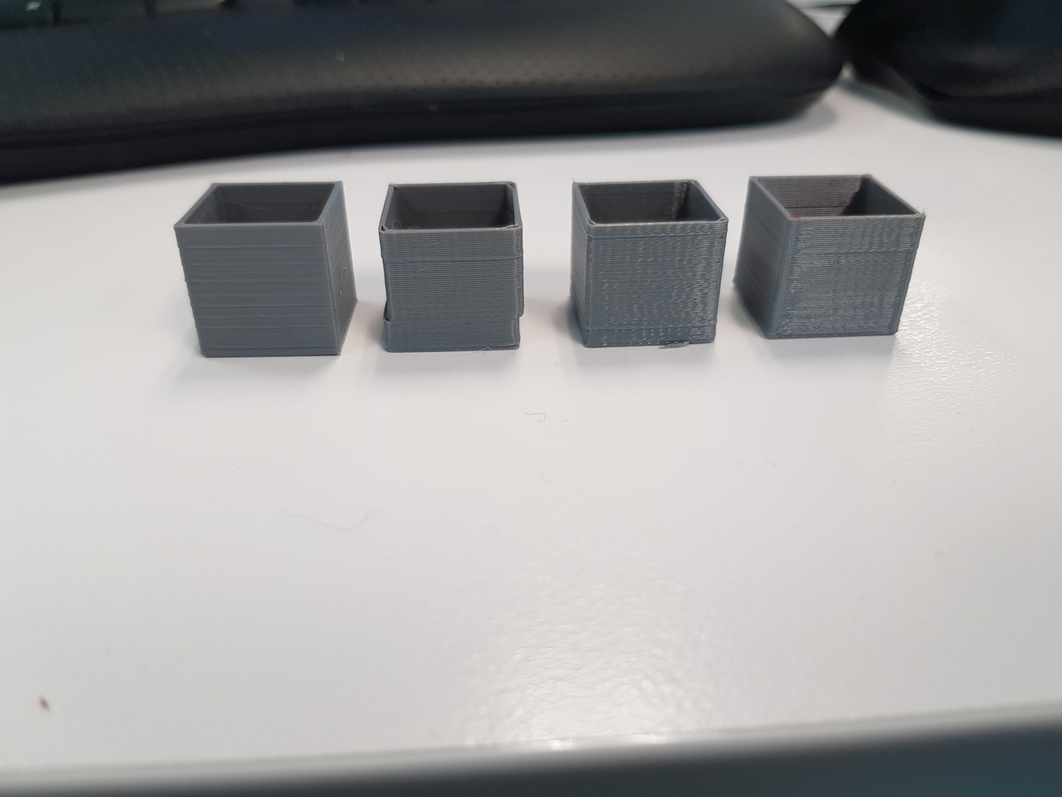
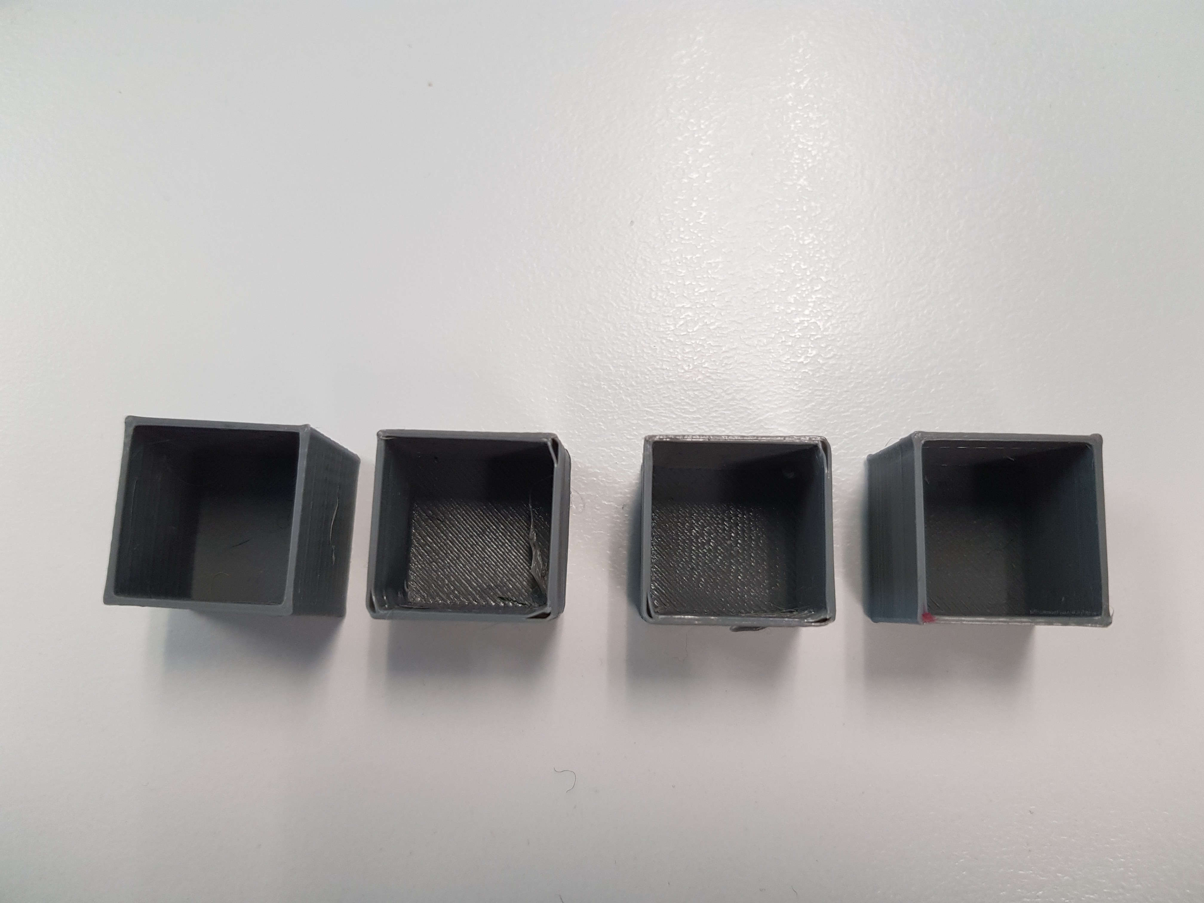
Left To Right All in PETG -
- Existing Jerk Code, Linear Advance 0.2 (Slightly over extruded).
- Junction Deviation Code, Junction Deviation 0.1, Linear Advance 0.2
- Junction Deviation Code, Junction Deviation 0.02, Linear Advance 0.2
- Junction Deviation Code, Junction Deviation 0.02, Linear Advance Off (red dot is marker after print for me to id)
I haven't fully calibrated the PETG, it has been a pain in the proverbial - either starved or overextruded after retraction, which is why I started looking into LA, which is where I noticed this problem. I'll repeat the tests/do some more tests with PLA which should produce some better results.
Squid116
on 2 May 2018
Progress is looking good! I guess we were closer than I thought.
I wonder if this helps at all with the mysterious lost steps seen at #10446. It would be good to pinpoint the exact cause of that before junction deviation is integrated.
If Junction Deviation is added as an optional feature, that would be best at this point, since we don't know how well it will perform with different types of machines, and it would be good to get feedback over time.
thinkyhead
on 2 May 2018
@thinkyhead I'll do some more tidy up and prepare a PR hopefully tonight, do you see a logical place in configuration(_adv?).h for the relevant settings to live? (Currently I have values for junction deviation enabled, junction deviation, and include e in junction deviation).
Squid116
on 2 May 2018
Just tried a print (2 20mm cubes rotated at 30 and 45 degreees) with triple!!! my normal acceleration, and not one skip! two bloody good looking cubes.
I am having some issues with z-hop ending up further down than the start height, trying to work out if it is because of this change, or something else. With z hop disabled it comes up perfectl height.
Edit: sorry for closing and reopening the issue several times, stupid laggy internet on my phone.
Squid116
on 2 May 2018
Sweet! ... :) ... The only thing that remains is to fix Linear Advance for Bezier interpolation ... :)
 ejtagle
on 2 May 2018
ejtagle
on 2 May 2018
@ejtagle as far as I read out of the messages here the jerk code is part-finished up to now?
As soon as it's fine for testing, I will give it a try as I'm very intrested to see the results. You can assume LA will be adopted quite fast if the new code is proven to work.
Sebastianv650
on 2 May 2018
New Jerk Code + Bezier interpolation + New LinearAdvance = Much faster prints with good quality 👍
ejtagle
on 2 May 2018
I will review the code. I am busy right now with other things, but i was planning to do the jerk code port myself. @Squid116 won
Yes, porting the whole GRBL planner to Marlin is not easy at all. The codebases have diverged quite a bit
ejtagle
on 2 May 2018

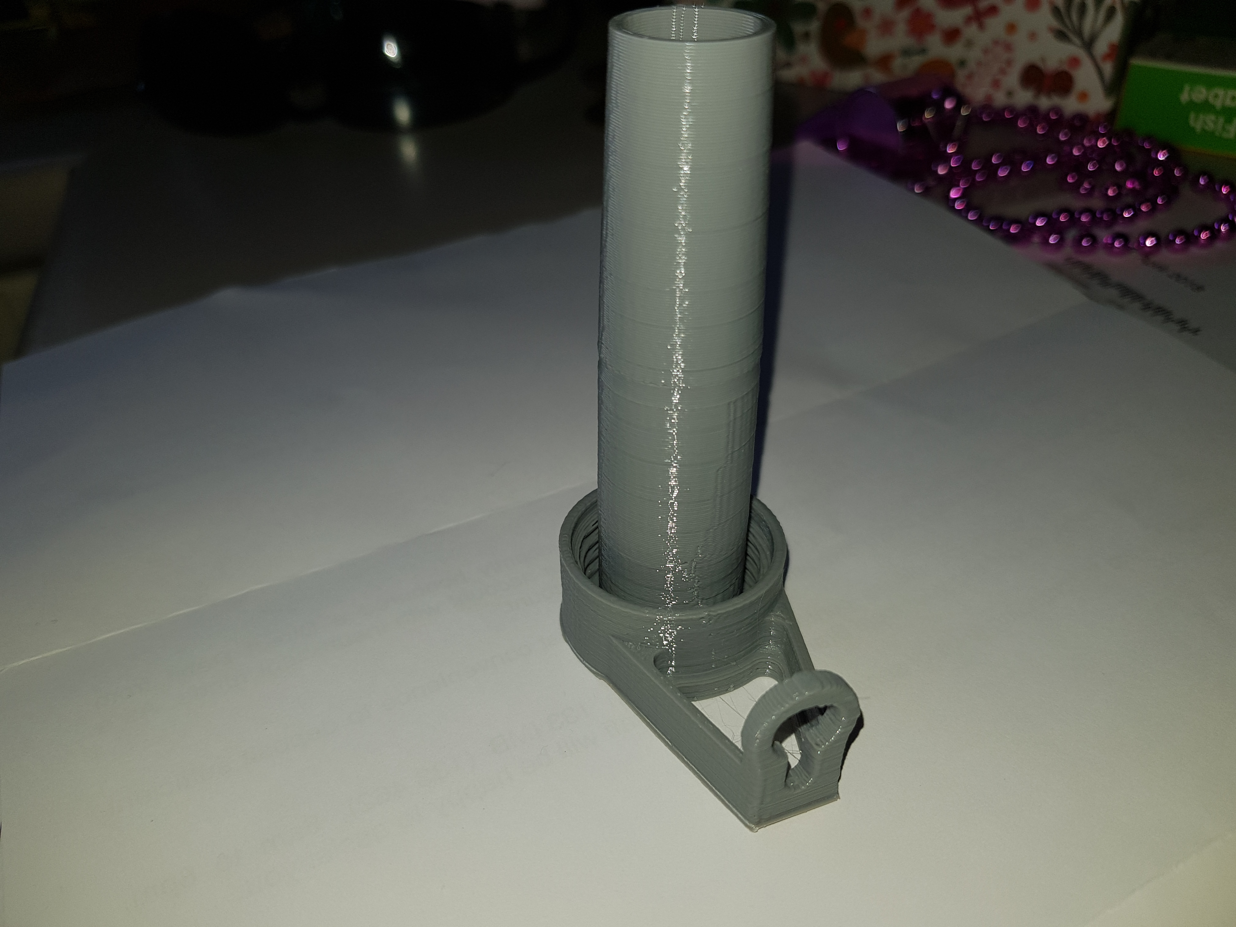
After printing a few more cubes, I had a go at something a bit more complicated, and not bad result. Still some strings and blobs on the fine details (I might need to try a smaller nozzle for this print), but this print has failed numerous times with the old jerk code. Still printing with triple my previous safe acceleration!
Edit: before anyone gets too excited by the change in acceleration, it went from 200 to 600. Big deal for me, but might not rock your world!
Squid116
on 2 May 2018
I am having some issues with z-hop ending up further down
Are you referring to G10 / G11 firmware retraction with Z hop, or just regular G1-based Z-hop?
thinkyhead
on 3 May 2018
I'll do some more tidy up and prepare a PR hopefully tonight, do you see a logical place in configuration(_adv?).h for the relevant settings to live? (Currently I have values for junction deviation enabled, junction deviation, and include e in junction deviation).
The best spot would probably be right after MINIMUM_STEPPER_PULSE. Junction deviation fits the theme in that small section.
thinkyhead
on 3 May 2018
@thinkyhead Yeah G11, I see from another issue others are having problems, so have just left it out for now,
Squid116
on 3 May 2018
So, overall I find it very interesting that the layer shift is cleared up by changes in the jerk algorithm. One thing I noticed about Cura is that by default it overrides the Jerk settings and pushes them pretty high — double what would be appropriate for the current Marlin, but probably ok for older Marlin firmware, and maybe ok for Ultimaker's current firmware.
However, I've tried reverting the jerk code back to what it was with 1.1.8 and put it out there for troubleshooters to test. It wasn't much different at all from what we now have, so I wasn't expecting a big impact. Anyway, I'm headed over to that issue now to see if anyone has followed up and tested that reverted code to see if it put an end to lost steps or not.
thinkyhead
on 3 May 2018
Yeah
G11, I see from another issue others are having problems, so have just left it out for now,
Are you using it with UBL, ABL, or no leveling at all?
thinkyhead
on 3 May 2018
UBL. so it is in line with what others are seeing...
Squid116
on 3 May 2018
Re the layer shifting, I'v had a hard time finding Jerk values low enough to work without heaps of shifting, but still high enough to have any sort of quality in corners. I have probably had it a bit too high, but willing to walk close to the edge for the sake of quality.
Squid116
on 3 May 2018
More testing on more complex parts - still looking👍
Squid116
on 3 May 2018
Which code base do you use, @thinkyhead branch?
Sebastianv650
on 3 May 2018
Yeah based on that @Sebastianv650, there was a bit more to do, but not a heap. I'll stop playing with it and get a pull request together.
Squid116
on 4 May 2018
a bit more to do, but not a heap
It seemed like a big heap at 4:30am… I'm glad it wasn't!
thinkyhead
on 4 May 2018
It seemed like a big heap at 4:30am… I'm glad it wasn't!
But I stopped short of the full planner implementation you were planning on doing... that would certainly be too big at 4:30!
Squid116
on 4 May 2018
You can submit your PR to my fork, if you prefer. Probably simpler if you started with that branch.
thinkyhead
on 4 May 2018
Sorry - family life has been in the way of getting this together, I'll get a pr up to your branch tomorrow, it isn't up to scratch, but enough to demonstrate it is effective.
Squid116
on 5 May 2018
@thinkyhead my latest is at: https://github.com/Squid116/Marlin/tree/bugfix-1.1.x
I haven't done a PR, as there are numerous changes not related to this - I think you might need to bring your branch up to latest bugfix 1.1.x?
Squid116
on 6 May 2018
I was playing around with this, and was getting worse results than with the regular jerk setting, even when setting it to .005 deviation. The X axis was experiencing more force, and I was seeing little micro shifts when it would get a little bit of a knock. I got to thinking, on the CR-10S I have, the only thing experiencing centripetal force is the frame. On a 90 degree turn, the X axis is experiencing maximum force. On a machine where the whole head is moving for X and Y, junction deviation makes a lot of sense for the axis that are experiencing inertia together, but when the bed is moving separately, it doesn't give good results. It did fix the weird blob from slowing down before accelerating on the K factor test.
Also, I was having the problem where high travel speeds would mess with the mesh leveling, and cause skips, and this improved it but the acceleration across the bed was still wonky. Strangely, the Z jerk value affected this still, somehow.
 hoffbaked
on 7 May 2018
hoffbaked
on 7 May 2018
@hoffbaked Which version of this code are you running? the one from my branch? What does your acceleration look like?
Grab the spradsheet @Sebastianv650 posted and play around with the figures to determine the ideals - for mine with a junction_deviation of -0.02 and acceleration to 600 this limits a 90 degree corner to 5.38 mm/s which is less than my previous jerk settings of 10mm/s.
Based on the config at: https://github.com/MarlinFirmware/Marlin/blob/bugfix-1.1.x/Marlin/example_configurations/Creality/CR-10S/Configuration.h to mimic the CR-10S's jerk of 20 at acceleration of 575, I get a value of 0.3 which will slow a 90 degree corner to 20.41, so I can't see that a setting of 0.005 would cause forces that didn't exist previously - this would cause that corner to slow to 2.64 at the junction, much less than the current jerk settings would have...
Squid116
on 8 May 2018
I didn't want to give up the bezier acceleration, so I made your changes in the 2.0 branch I had. I tried using the acceleration of 800 that worked well with the jerk value of 8 that I've been using. I tried reducing acceleration to 300, and it still wasn't as good as my results with the normal jerk code.
hoffbaked
on 8 May 2018
Can you share the planner.cpp you have, I can run an eye over it and see if it looks ok? As you can see in the thread, I had a few hiccups with things not quite working, so I know a few things not to do!
Squid116
on 8 May 2018
Here are the changes. It didn't seem to make a difference in practice, but I fixed the couple of typos when the E axis is included:
planner.cpp.zip
I think the problem is that with my printer, if I slow it down enough for a 90 degree corner, then anything sharper is crazy slow. When the X and Y are uncoupled like on my printer, it seems like it makes more sense to consider them individually and use the minimum. At least I know it works to help me nail down whatever is shifting on my X axis! : )
hoffbaked
on 8 May 2018
I notice on the spreadsheet, it starts spitting out crazy numbers at really small deflections. I you go from 40mm/s on X to 39mm/s and 1mm/s on Y, it gives a result of almost 500mm/s!
hoffbaked
on 8 May 2018
@hoffbaked that is what the vmax_junction = min( vmax_junction, min(block->nominal_speed,previous_nominal_speed)); accounts for, it is only going to slow the printer down if the junction deviation results in a max junction speed lower than the existing segments.
Squid116
on 8 May 2018
Ah, but that gets taken care of further down. I did notice it sounded like either it was making contact on some travels, or it was doing something the stepper didn't like. I tried adding a z hop, and it was better, but still not as good as the old code for me. I'll mess with it some more tomorrow. Also, I was thinking some more, and at when the angle is less than 90 degrees, the axis is reversing and needs to slow down more than the 90 degree case, so it still seems like this should work better on my machine in theory.
hoffbaked
on 8 May 2018
Are you using the USE_EXTRUDER_IN_JUNCTION_DEVIATION? Obviously as you have seen, I haven't been using it/testing it (yet).
Squid116
on 8 May 2018
I tried both. There were a couple of small typos, so I figured I was in uncharted water on that one. I didn't notice any difference.
hoffbaked
on 8 May 2018
I forgot, I took a couple pictures of the results. Here's with the jerk code set at 8:
And here's the same file with junction deviation set to .005, if I'm remembering correctly:
hoffbaked
on 8 May 2018
@hoffbaked : From your photos, i do agree the new jerk code worsens the result for your prints. But i also see (in the "good" print) that you are having overextrusion on corners. And quite a bit of overextrusion!.
The new jerk code, as far as i understand it, makes faster prints by allowing better estimations of centripetal forces, then it allows the printer to take those corners faster. And faster means more irregular deposition of overextruded plastic.
My first suggestion would be, of course, to recalibrate the extruder... Measure the exact filament diameter of the plastic and re slice the model with that exact diameter.
Also make sure to measure the extruded lenght per extruded steps and recalibrate so there is a perfect match.
(i think you have already done all the above steps) . Probably the overextrusion (if still there) is caused by the pressure buildup in the nozzle. In such case, the only hope is either to print slower, or wait until i finish the linear advance algorithm version that is required for bezier interpolation)
Right now i am working on cleaning up the stepper ISR so it is easier to integrate the new required linear advance. And, yes, the algoritm is just a substraction, so it should run in realtime even on an AVR...
ejtagle
on 8 May 2018
So far, I think I'm having better luck using 'acceleration' instead of 'block->acceleration'. Since it's used as the cornering force, it doesn't really make sense to corner more gently when your extruder jerk is too low for your k factor. It almost should be a hard coded value, since it linearly scales the junction deviation, anyway.
hoffbaked
on 8 May 2018
Well, I figured out the problem. In testing, the screw on the pulley of my X stepper had slightly loosened. : P Yes, with a bowden and the bezier jerk enabled, I've grown accustomed to corner lumps. I'm eagerly awaiting a linear advance update. I still believe, at the very least, the acceleration value used should at least be the value prior to being limited by the linear advance code. It seems to be working a bit more predictably just using acceleration, and I wouldn't think it would cause an issue with the Z axis, since it's not actually doing any acceleration, and the rates are near zero for anything near a reversal.
hoffbaked
on 9 May 2018
linear advance algorithm version that is required for bezier interpolation
That should be some interesting looking code…
thinkyhead
on 9 May 2018
Just recognised there was a PR for new jerk 👍 Have to steal myself some time next week to test it I guess.
But what's that bezier interpolation you're talking about, it's not referenced inside the PR?
Sebastianv650
on 9 May 2018
BEZIER_JERK_CONTROL was added a few weeks ago by @ejtagle to the 2.0.x branch, and I recently ported the AVR implementation over to the 1.1.x branch as well.
thinkyhead
on 9 May 2018
So, I thought of an edge case last night which is affecting tight rounded corners, and diagonal infill to a lesser extent. The first line of a decimated round corner is almost tangential the the long line prior, so there is very little for the corner, and then the following segment is much too short to decelerate for the next corner. On diagonal infill, you can feel the asymmetry pretty easily.
I’ve had best results with just hard coding a corner acceleration speed, since it really shouldn’t be tied to any other acceleration, anyway. So the speed limit for a corner can be computed with only the vector. If there’s some way to even roughly know if the next line segment is too short, taking the min of the two corner speeds would solve most real world cases.
Ideally, the deceleration should be able to propagate backward. This might have a lot to do with the really rough speed transitions with UBL boundaries.
hoffbaked
on 10 May 2018
Huh. It looks like there is a reverse pass that should take care of it. Maybe it's not recalculating the line that's longer than the nominal length, even though it should.
hoffbaked
on 10 May 2018
Hopefully someone with more knowledge can jump in, but I think the problem is that on the reverse pass kernel, if current->entry_speed is equal to the max_entry_speed already, it doesn't get recalculated! It seems like the check should be:
if (current->entry_speed != max_entry_speed || TEST(next->flag, BLOCK_BIT_RECALCULATE))
And, also only set the flag if the entry speed changed.
hoffbaked
on 10 May 2018
So, this definitely fixed the asymmetry on diagonal infill, but it still seems to take tight rounded corners very fast. I had the cornering speed up pretty high for testing, jerk seems really minimal, even at a high value, except on rectangles with tight rounded corners.
hoffbaked
on 10 May 2018
So, I just realized a fatal flaw with this algorithm. The correct speed going around the corner would be calculated base on the curve it's going around. If you broke that curve up into an infinite number of lines, the angles are all 180°, and this algorithm wouldn't decelerate at all for the turn! In real life, it looks like the rounded corners have about six lines at 165°, so we're treating what is really close to a 90° angle as a 165° angle.
It seems like if the prior line and the current one are less than a certain length, we need to find the proper speed around the circle those three junctions make. It seems like it'll just replace the junction deviation value with a different radius, and the speed will propagate backward with the fix to the reverse pass code.
hoffbaked
on 10 May 2018
If you broke that curve up into an infinite number of lines……
@hoffbaked — How do you suppose Grbl avoids this issue? Does it only get sanitized G-code because CNC slicers are smarter? Or is it just that for routing and engraving the speeds are considerably lower than those we use for 3D-printing?
Assuming that very tight corners get subdivided too far, we hit another potential issue, which is planner starvation, as the segments are so small that they complete too quickly for the planner (and serial input) to keep the block buffer filled. The best policy is to avoid subdividing curves so much that it comes up against the firmware's limits. There's only so much lookahead we can do to prevent these edge cases, and we definitely hope slicers will override the feedrate on these kinds of corners.
thinkyhead
on 10 May 2018
I have compared the Marlin planner and the GRBL planner, and there is still some differences. I will port it to Marlin (in fact, changes are absolutely minimal) and send a PR once i tested it, so anyone can evaluate it... ;)
ejtagle
on 10 May 2018
@hoffbaked You are right: Angles are very near 180 degrees with short lines, but segments are pretty small.
A very interesting question arises here: The jerk control algorithm was designed to control jerk between movement segments. And limit them to something the printer could handle.
If the printer can handle the nearly sudden change of direction, then i actually see no problems on high speed cornering ... Quite in fact, keeping the linear speed constant helps with plastic deposition (there is no need to change pressure of the nozzle.
So, the main question is... Are we dealing with some kind of resonance you want to avoid ? ... Or losing steps ? ... Or a plastic deposition problem ? ;)
(The algorithm could be fixed by taking into accounf the deltaAngle/deltaDistance between movements, if a slowdown is what is needed...)
(https://onehossshay.wordpress.com/2011/09/24/improving_grbl_cornering_algorithm/)
ejtagle
on 10 May 2018
Well, the slicer seems to generate corners like this that are probably less than a mm radius, so 5 microscopic segments, with six 165 degree angles. For all practical purposes, it's a 90 degree angle that's being taken at full speed! There was a thin infill line between two walls that got my attention. I just laid eyes on the source code for the first time a couple of days ago, and didn't really delve into it until today, so I'm a little out of my depth. I was excited brushing off my ancient geometry knowledge to figure out the radius from the two segments, but then I remembered there's an extra axis vs my sheet of paper. : P
hoffbaked
on 10 May 2018
So, it looks like grbl takes care of it with this line:
// Calculate maximum entry speed for last block in buffer, where the exit speed is always zero.
current->entry_speed_sqr = min(
  current->max_entry_speed_sqr,
  2 * current->acceleration * current->millimeters
);
Basically, as segment length approaches zero, so does speed. I'll try it out...
hoffbaked
on 10 May 2018
Exactly... You found out... That is the missing piece of the GRBL planner ;)
ejtagle
on 10 May 2018
I've been using a defined value for junction acceleration, since coasting through a corner at a higher speed helps, but linear advance is the limit for my block acceleration, most likely. So here is the change:
vmax_junction = MIN4(
  vmax_junction,
  block->nominal_speed,
  previous_nominal_speed,
  SQRT(2 * JUNCTION_ACCELERATION * block->millimeters)
);
I estimated the segment length on my problem rectangle is .1mm, so I found that acceleration of 1000, and a deviation of .05 gave my a corner speed on 10 for both methods with a 90 degree angle and a .1mm segment length.
It definitely solves the problem, but it seems like it's slowing down the writing on the bottom of benchy unnecessarily. I thought of a very rough approximation last night, laying in bed. If I multiply the segment length by how many of them at that length would complete a circle, it would be a very rough circumference of the circle, and then I found an acos approximation that's only multiplication. I'll mess around in Excel and see how it works in practice.
hoffbaked
on 10 May 2018
The approximation I came up with look like like an improvement on the Grbl method. Even only taking the length the current segment, I can't find a case where the min of the two wouldn't be a reasonable speed.
On small deflections with a really short segment, it gives results in line with a 90 degree turn with the regular method.
I found a problem with the spreadsheet that I'm fixing, and then I'll upload it.
hoffbaked
on 10 May 2018
Well, when I started calculating the number of sides properly, the errors in the acos approximation started adding up fast. If a subtract the maximum error of the algorithm of .18 rads, it then starts looking pretty good. Would probably only need to check it for large angles, anyway:
I'll try it out my printer.
hoffbaked
on 10 May 2018
Would probably only need to check it for large angles, anyway
Any heuristics we can do to avoid extra calculation are most welcome.
thinkyhead
on 10 May 2018
@thinkyhead Just keeping speed squared can easily save 10000+ cycles per planning... So don´t worry: There are easy changes than can speed up the planning process quite a bit...
ejtagle
on 10 May 2018
Okay! It seems to be working good. I somewhat arbitrarily cut it off at 1mm on then on anything with fewer sides than an octagon. With this, and the reverse pass actually recalculating things, a corner acceleration value of 1000 junction deviation of .05 are pretty reasonable. If the cycles can be spared, a better acos could be used. For all I know, it may be already calculated in a different place. Here's what my block looks like:
// NOTE: Computed without any expensive trig, sin() or acos(), by trig half angle identity of cos(theta).
if (junction_cos_theta > 0.999999) {
  // For a 0 degree acute junction, just set minimum junction speed.
  vmax_junction = MINIMUM_PLANNER_SPEED;
}
else {
  junction_cos_theta = max(junction_cos_theta, -0.999999); // Check for numerical round-off to avoid divide by zero.
  const float sin_theta_d2 = SQRT(0.5 * (1.0 - junction_cos_theta)); // Trig half angle identity. Always positive.

  // TODO: Technically, the acceleration used in calculation needs to be limited by the minimum of the
  // two junctions. However, this shouldn't be a significant problem except in extreme circumstances.
  vmax_junction = SQRT((JUNCTION_ACCELERATION * JUNCTION_DEVIATION * sin_theta_d2) / (1.0 - sin_theta_d2));

  if (block->millimeters < 1.0) {
    // Fast acos approximation, minus the error bar to be safe
    const float junction_theta = (RADIANS(-40) * sq(junction_cos_theta) - RADIANS(50)) * junction_cos_theta + RADIANS(90) - 0.18;

    // If angle is greater than 135 degrees (octagon), find speed for approximate arc
    if (junction_theta > RADIANS(135))
      vmax_junction = min(vmax_junction, SQRT(block->millimeters / (M_PI - junction_theta) * JUNCTION_ACCELERATION));
  }
}
@ejtagle I wondered why the speed was always squared!
hoffbaked
on 10 May 2018
You save TONs of cycles. There is no hardware acceleration for SQRT (or SIN or COS). All those functions are expensive to compute, so it makes sense to try to avoid them.
A floating point multiplication costs 100... 200 cycles... An SQRT could cost 1000... 10000 cycles as it uses newton / raphson iterations to converge, and each iteration requires some sums and multiplications, we are talking on speeding the planner 10x ... ;)
ejtagle
on 10 May 2018
Three backticks can be used for multi-line pre-text. Open with ```cpp for proper colorization.
thinkyhead
on 11 May 2018
@thinkyhead Thanks! I’m a bit new at this, obviously. : )
hoffbaked
on 11 May 2018
Here's a modification that eliminates one SQRT operation:
// NOTE: Computed without any expensive trig, sin() or acos(), by trig half angle identity of cos(theta).
if (junction_cos_theta > 0.999999) {
  // For a 0 degree acute junction, just set minimum junction speed.
  vmax_junction = MINIMUM_PLANNER_SPEED;
}
else {
  NOLESS(junction_cos_theta, -0.999999); // Prevent -1.0 to avoid divide by zero.
  const float sin_theta_d2 = SQRT(0.5 * (1.0 - junction_cos_theta)); // Trig half angle identity. Always positive.

  // TODO: Technically, the acceleration used in calculation needs to be limited by the minimum of the
  // two junctions. However, this shouldn't be a significant problem except in extreme circumstances.
  float vmax_junc_sq = (JUNCTION_ACCELERATION * JUNCTION_DEVIATION * sin_theta_d2) / (1.0 - sin_theta_d2);

  if (block->millimeters < 1.0) {
    // Fast acos approximation, minus the error bar to be safe
    const float junction_theta = (RADIANS(-40) * sq(junction_cos_theta) - RADIANS(50)) * junction_cos_theta + RADIANS(90) - 0.18;
    // If angle is greater than 135 degrees (octagon), find speed for approximate arc
    if (junction_theta > RADIANS(135)) {
      const float limit_sq = block->millimeters / (RADIANS(180) - junction_theta) * JUNCTION_ACCELERATION;
      NOMORE(vmax_junc_sq, limit_sq);
    }
  }

  vmax_junction = SQRT(vmax_junc_sq);
}
Better is also no SQRT on foward and reverse pass of planner,... ;)
Well, now, i think we are ready for primetime! .. I tried all the changes to the junction code proposed by @hoffbaked and they work great!! 👍 ... I have integrated all the changes to my refactoring of the Planner, i want to credit all the people that have invested a ton of time on this, including you @thinkyhead and you @hoffbaked, so i will kindly ask @thinkyhead to remove my name from the following PR and credit the people involved in this GREAT!! improvement.
Allow me a bit of time so i open the PR...
ejtagle
on 11 May 2018
remove my name
No way. Everyone gets a co-authored-by tag.
How else do we know who to blame in future? 😉
thinkyhead
on 11 May 2018
ok. I do agree to coauthor it, but i want to be blamed for all the other bugs 👍 (i have done a full print with no issues at all ;) )
ejtagle
on 11 May 2018
Oh, man. I just went to print something, and changed the build plate, so I re-leveled the mesh. Now the extruder is doing really bizarre things. I haven't done a mesh level in a while, so it's probably that, but it makes me uneasy. : P @ejtagle Your bezier jerk code was what got me to install the bleeding edge code base in the first place!
hoffbaked
on 11 May 2018
Ah. I can’t test it for a few hours, but I realized
I have a machine profile with a different z offset, and I probably don’t have firmware retraction checked. I’m guessing I have an old, buggy version of auto retract, or it doesn’t play nice with the new code, somehow.
This makes laying awake at 4am thinking about cornering velocities all worth it! : )
hoffbaked
on 11 May 2018
It works beautifully. Your changes have no impact on UBL.
ejtagle
on 11 May 2018
@hoffbaked There has been reports on Extruder strange noises caused by latest Linear advance code. All the changes i did on that PR are my best attempt to clean up code and make it possible to add the proper Linear Advance algorithm for the Bezier interpolator.
I tried to print something with your changes + bezier interpolation, and movements are very smooth, yet the printing takes 20% less time than before... ;)
ejtagle
on 11 May 2018
@thinkyhead : By the way, what i meant by "remove my name" is not to literally remove my name. Just to give credit where credit is due. It would be unfair to be the coauthor with you of this PR, when @hoffbaked was the man behind the effort and tests ... 👍
ejtagle
on 11 May 2018
I wish I could give everyone involved a Tesla.
thinkyhead
on 11 May 2018
@thinkyhead Me too!! Yes. It works fine if I turn on firmware retraction in my slicer, or, I assume, turn off auto retract. With it on, it made strange noises, and seems to generally want to run backward. : P I'm almost bummed that my direct extruder arrived today with new linear advance in the works. : D
hoffbaked
on 11 May 2018
Test results are sounding very encouraging. Hopefully JD becomes a viable replacement for the old jerk code, but we can keep old-school jerk around for cases where speed is needed, or where JD might not fit well with certain kinematics.
It works fine if I turn on firmware retraction in my slicer, or, I assume, turn off auto retract
The options are:
- Slicer generates all retract/recover moves as E-only moves. When auto-retract is enabled, Marlin intercepts these E-only moves and replaces them with
G10/G11moves. - Slicer generates
G10/G11instead of E-only moves, andFWRETRACTmust be enabled in the firmware for those to work at all. Auto-retract has no interaction with these G-codes. - Slicer does "wipe" moves during retraction. Auto-retract ignores these moves because they aren't E-only.
Anyway, auto-retract might still have some bugs. It needs yet another proper audit. G10/G11 (and thus auto-retract) have not had a good relationship with UBL due to the way fwretract.retract overrides the current position. Maybe G10/G11 are in better shape after recent changes to fwretract.retract, but the new code needs to be put through more paces before we can fully sign off on it.
The main big change was the addition of a special type of planner block whose only job is to set the current position. This "sync block" has an entry/exit speed of 0, so we need to make sure that it interacts with the jerk and acceleration handling properly. It would make the most sense for this block to actually have its entry and exit speeds set to the entry/exit speed of the previous block. But since its duration is zero, it should be essentially skipped in the forward/reverse passes.
To test this block, just insert G92 commands in-between moves. It doesn't matter what the position is set to. The block will always be inserted. But setting it to the XY from the previous G1 would give the cleanest test. If it behaves just like M400 and causes the previous move to decelerate to zero, then the next move to start from zero, that's ok. But it would be a bonus if sync blocks could cause no interruption in motion at all.
thinkyhead
on 11 May 2018
That is a very good idea, @thinkyhead -- You are right, the sync block should not decelerate to 0...The Stepper ISR skips those blocks, But those blocks cause the planner to decelerate and then accelerate again in the neighborhood of the block.
ejtagle
on 11 May 2018
@ejtagle I'm truly honored! : D I don't even mind that my user name is misspelled in the title. ; )
hoffbaked
on 11 May 2018
@ejtagle Am I thinking about this right? Is the linear advance on an s curve an acceleration instead of a jump? If so, that would get rid of a lot of extruder racket!
hoffbaked
on 12 May 2018
Or more technically, for an s curve acceleration, added extruder acceleration on the first half, deceleration back down on the second half.
hoffbaked
on 12 May 2018
Linear advance doesn't exactly do an S-curve acceleration, but it does decouple the acceleration of the E axis from the trapezoid of the XY movement, so it can start early (or at least faster) to build up pressure in the move, and let off early (or decelerate faster) to allow pressure to dissipate. Some have compared the pressure algorithm to tuning a spring… but it's more like tuning a s'more.
thinkyhead
on 13 May 2018
@hoffbaked and @thinkyhead Both are right. The "advance" that uses LA is the derivative of the acceleration relative to time. That is the way Pressure compensation should work.
But, on the default implementation of the speed curve (the old trapezoidal shape) acceleration is constant except in 3 places, where it abruptly changes: The start of the trapezoid, the place where the speed reaches its nominal rate, the start of deceleration. Those are the ONLY places.
That is why the current LA code ONLY adds or substracts pulses in those specific places of the trapezoidal profile,
But, with bezier curve, we must ACTUALLY calculate the derivative (or at least an approximation of that) of the acceleration and use THAT to compensate.
All the required data is available at the Stepper ISR, so it should not be a problem,
And @hoffbaked : You are absolutely right: As the Bezier curve causes acceleration to vary gradually, the Extruder LA advance will also vary gradually and there will never be rattling . It will run smooth as all the other axis
ejtagle
on 13 May 2018
@ejtagle Ah. I see that we're using cubic bezier curves. Is there some reason quadratic doesn't work? I don't know much about it, but it seems like the derivative is just a triangle profile the same area as the square for the trapezoidal acceleration: http://www.galilmc.com/news/dmc-programming-motion-controllers/s-curve-motion-profile-using-contour-mode
hoffbaked
on 14 May 2018
No, there is no reason. We use Bezier just because equation simplifies quite a bit and evaluation is not a big problem, even on AVR. The S curve gets derivative of acceleration = 0 at the start and end of movement. The Bezier also gets the 2nd derivative of the acceleration = 0, so it is supposed to be even softer.
In practice, there is a notable difference on vibrations.
ejtagle
on 14 May 2018
Now that I thought about it for a minute, the physical jerk (and the linear advance!) would be a parabola instead of a triangle, which would be smoother with less of a peak, too.
hoffbaked
on 14 May 2018
Exactly 👍
ejtagle
on 14 May 2018
Hmmm. In the current linear advance, the extruder jerk actually relates to a physical jerk value! Just not of the extruder. : )
hoffbaked
on 14 May 2018
It's realy a joy to read the progress in here, looks like some awsome guys put their head into it - great work! 👍
Sebastianv650
on 14 May 2018
@ejtagle @thinkyhead A thought occurred to me last night... On the Z axis, we've got the force of gravity giving us free acceleration going down, and free deceleration going up. Other than getting the lead screw and motor rotating, you'd have to outstrip a free-fall going down to impart any load on the stepper. On a Z hop, we're wasting a bunch of free acceleration! I don't know what that would add up to on a print. This would be super easy, since it's just boosting the acceleration value in the direction where gravity is assisting.
Similarly, when the spring of the extruder is loaded, there is free acceleration on a retraction, and free deceleration when it loads. I experienced this when operating the extruder from the menu. It turns off the stepper after the extrusion, and the gear springs backward.
The spring assist on the extruder is a lot harder problem, since it's just an initial boost in velocity on retract, and ever increasing force on the other side as pressure builds. But it seems like it could work like this:
On retraction, give some initial velocity if the spring is loaded.
On unretraction, use JUNCTION_DEVIATION_INCLUDE_E to carry some speed through to the initial extrusion, and boost the deceleration on the unretract assuming the spring will scrub off the momentum.
If I'm thinking about this correctly, it seems like that would improve print quality, and slightly improve print speed.
hoffbaked
on 14 May 2018
You are probably right @hoffbaked ...
ejtagle
on 14 May 2018
I was thinking the junction deviation code needed to respect the Z jerk setting, since it's so far out of line with the rest, if it's not a delta printer. As a little bit of an experiment, I'll only respect it when it's working against gravity and see how it runs. My dad is getting a new hip tomorrow, and I'll be taking over a lot of duties in the family business for a little while, so I'll try to get something thrown together and tested.
hoffbaked
on 14 May 2018
free acceleration … free deceleration
I prefer to think of these as just less inertia and more inertia. The steppers have a pretty strong magnetic hold, so I hesitate to consider the gantry as "falling" or the extruder as "springing," exactly. But certainly, the net effect is similar!
thinkyhead
on 15 May 2018
My dad is getting a new hip tomorrow, and I'll be taking over a lot of duties in the family business for a little while
Best of luck! We're going miss your help around here. Be sure to check in from time to time.
thinkyhead
on 15 May 2018
Just wanted to report I redid my nonagon testpattern (see https://github.com/MarlinFirmware/Marlin/issues/10341#issuecomment-379859475) with the new jerk code enabled, here is the result:
0.00 (initial speed, starting from 0)
70.00 (continued block, second half = nominal speed)
19.34
19.34
19.33
19.35
19.35
19.33
19.34
19.33
19.35
19.33
19.34
19.33
19.35
19.35
19.33
19.34
19.33
Looks like it works just perfect, at least in this short only travel moves test 👍
Sebastianv650
on 22 May 2018
@Sebastianv650 — That's encouraging news!
thinkyhead
on 25 May 2018
@thinkyhead @Sebastianv650 @ejtagle @hoffbaked
I'm pretty happy that everything in my initial bug has been solved (plus heaps more) - is everyone happy to close this issue? Anything else the pops up should get its own issue.
Squid116
on 6 Jun 2018
Well I'm definitely still experiencing it but i know that linear advance 2.0 is still in the works so if you want to close this I'm fine with waiting.
jokeman3000
on 6 Jun 2018
@jokeman3000 is your problem due to the junction speed, or is it purely a LA thing?
Squid116
on 6 Jun 2018
I believe linear advance, as it occurs with and without junction enabled. I did not have this issue with 1.0, it presented with 1.5 and it is just as you described in the first post.
jokeman3000
on 6 Jun 2018
The slowdown at the junction will occur without junction enabled - the jerk calculation is wrong. Maybe it hasn't been noticeable previously, but it was there.
Squid116
on 6 Jun 2018
Perhaps it could be with how the kfactor test is generated for 1.5, I'm not sure. I'm happy to test any alternatives anyone comes up with to help isolate the issue.
jokeman3000
on 6 Jun 2018
is everyone happy to close this issue?
I suppose that as long as it's still being seen in the current bugfix branches, we might as well leave it open and continue to try to solve the problem.
thinkyhead
on 8 Jun 2018
@jokeman3000 I just retested the decribed problem and on my printer it's eleminated by the junction deviation option. If you still get the slow down to 0 issue, can run this code to see if we are talking about the same problem:
G28 X ; Home X
M204 T100 ; Set travel acceleration to 100mm/s²
G1 X80 F1200 ; Slow move
G1 X130 F4200 ; Fast move
G1 X160 F1200 ; Slow move
If you can't hear a slow down to zero before it accelerates to the fast section, you have another problem.
Sebastianv650
on 8 Jun 2018
OK - so ignoring the output quality (need to re-level) and the wire mess (in the middle of some cleanup), I think this video demonstrates the issue well. I switched to the alternate pattern to see if there were any changes but it seems as k increased, movement overall slows down. It really starts becoming evident at the 30 second mark. As soon as the test finishes and it goes about printing numbers and such, speed increases significantly.
jokeman3000
on 10 Jun 2018
You might call me blind, but I can't see the extruder going to full stop during a straight move in your video?
Sebastianv650
on 11 Jun 2018
I'm not sure how that's relevant, is linear advance about stopping or optimizing extrusion during movement?
The observation is that as K increases movement becomes slower, which junction deviation has definitely improved but the issue remains.
I assume that if it was working properly, the speed of the x,y movement should be consistent from line to line (it is the same movement after all), the only thing different from one line to the next would be the pressure of the filament coming out calculated based on k.
Again, if you want to close this issue that's fine, I'm just pointing out there is still an issue.
jokeman3000
on 11 Jun 2018
Isn't Linear Advance v1.5 supposed to do just that, slow the movement if necessary to ensure that the maximum E jerk value is respected?
On my printer I have tuned the E jerk value to 8, so these slow downs are minimized but the extruder still can keep up with it.
 FiCacador
on 11 Jun 2018
FiCacador
on 11 Jun 2018
I guess, what I go back to is in the following quote from the lin advance article (http://marlinfw.org/docs/features/lin_advance.html)
While you will most likely not run into this on direct drive printers with filaments like PLA, it will happen most likely on bowden printers as they need higher K values and therefore faster speed adaptions. If this happens to an amount you don’t want to accept, you have the following options
This is a direct drive printer, acceleration is set to 3000 on x, y and the default for z and e0. If I'm seeing these results then either the defaults need to be adjusted or there is a bigger issue. I don't mention jerk because per my understanding junction deviation trumps it.
jokeman3000
on 11 Jun 2018
If LA is enabled, the E jerk value is still taken in consideration, even if using junction deviation.
@jokeman3000 what values for E0 jerk and k are you using?
FiCacador
on 11 Jun 2018
I can double check when I get home tonight but it EJerk is most likely 5.0.
The item printed in the video is the kfactor test with a range of 0-2. I think the movement issues begin at a K of 0.6 or 0.8.
jokeman3000
on 11 Jun 2018
Then it's the E jerk limitation for sure that is causing the slowdown.
FiCacador
on 11 Jun 2018
Happy to adjust and try something else, I just assumed the default was the safe value. What is a decent value to try with? It's a e3d titan (and aero).
Perhaps the defaults need to be adjusted given the linear advance 1.5 requirements?
jokeman3000
on 11 Jun 2018
Yes, the slowdown is due to your e jerk limits. The issue here was a stop to 0mm/s on line junctions, which is not related to your "problem". So I think we should close this.
The maximum ejerk value will depend on the extruder used, trial-and-error is the best method I know.
Sebastianv650
on 11 Jun 2018
Very informative discussion! Really helpful.
Still, I have one problem.
Initial, it has centripetal force implementation, although disabled.
https://github.com/prusa3d/Prusa-Firmware/blob/3.0.7/Firmware/planner.cpp#L954
then change to new implementation, and delete relate code.
https://github.com/prusa3d/Prusa-Firmware/blob/v3.0.8/Firmware/planner.cpp#L1028
Is it just a mistake made by Prusa folks?
 whimsycwd
on 3 Mar 2019
whimsycwd
on 3 Mar 2019
Initial, it has centripetal force implementation, although disabled.
That comes from Marlin 1.0.0.
then change to new implementation, and delete relate code.
Marlin 1.1.6 or 1.1.7 adopted the jerk implementation from Prusa Firmware, but it's only recently that Marlin added the new tested and optimized version of Junction Deviation.
thinkyhead
on 3 Mar 2019
This issue has been automatically locked since there has not been any recent activity after it was closed. Please open a new issue for related bugs.
![github-actions[bot] picture](https://avatars2.githubusercontent.com/in/15368?v=4&s=40) github-actions[bot]
on 18 Jul 2020
github-actions[bot]
on 18 Jul 2020
Related issues
 manianac
·
4Comments
manianac
·
4Comments
 modem7
·
3Comments
modem7
·
3Comments
 ahsnuet09
·
3Comments
ahsnuet09
·
3Comments
 esenapaj
·
3Comments
esenapaj
·
3Comments
 Bobsta6
·
3Comments
Bobsta6
·
3Comments
Most helpful comment
My initial reaction is, "Dammit, are we ever going to fix the bloody jerk code? We've been over this a million times, and there's no end to the problems."
I would recommend we take whatever Grbl is currently doing and completely replace our broken jerk implementation, assuming it's not just as bad.