Marlin: [FR] M592 From RepRapFirmware (nonlinear extrusion)
Just discovered the problem with extrusion error vs extrusion speed on my own experience.
See discussion
http://forums.reprap.org/read.php?262,802277
Don't have any option other than to print at low speeds at least for external perimeters to get better quality.
RepRap firmware guys did M592 for nonlinear extrusion compensation.
Hope such thing will be implemented in Marlin.
“
Most extruder drives use toothed shafts to grip the filament and drive it through the hot end. As the extrusion speed increases, so does the back pressure from the hot end, and the increased back pressure causes the amount of filament extruded per step taken by the extruder stepper motor to reduce. This may be because at high back pressures, each tooth compresses and skates over the surface of the filament for longer before it manages to bite. See forum post http://forums.reprap.org/read.php?262,802277 and the graph at http://forums.reprap.org/file.php?262,file=100851,filename=graph.JPG for an example.
Nonlinear extrusion is an experimental feature in RepRapFirmware to compensate for this effect. The amount of extrusion requested is multiplied by (1 + MIN(L, Av + Bv^2)) where v is the requested extrusion speed (calculated from the actual speed at which the move will take place) in mm/sec.
Nonlinear extrusion is not applied to extruder-only movements such as retractions and filament loading.
”
 ArtemKuchin
All 24 comments
Marlin's LIN_ADVANCE feature (recently updated to v1.5) is recommended to deal with back-pressure and regulation of line-widths. http://marlinfw.org/docs/features/lin_advance.html
 thinkyhead
on 28 Feb 2018
thinkyhead
on 28 Feb 2018
Yes i know, but does it really compensate for speed extrusion error when extruder just does not extruder the needed amount of filament?
I though LIN_ADVANCE is more like coasting and assumes that extruder physically extruder the given amount of filament. But it does not, see graph in the first message in the forum link i gave.
ArtemKuchin
on 28 Feb 2018
For clarification: Here is my test
http://forums.reprap.org/read.php?1,812325,812339#msg-812339
It is just a constant extrusion, not speed ups or speed downs. So, as i understand LIN ADVANCE will not help here at all.
ArtemKuchin
on 28 Feb 2018
@ArtemKuchin for me it's not clear what you try to compensate. Is it for slipping hobbed bolt? You table in the link is also confusing for me, at 360mm/min you got 1.13g, at 60mm/min you got only 0.69g? Doesn't make much sense to me, if something is slipping it should be the opposite way round.
If it's slipping, that's something that has to be solved by hardware in my opinion. I never had a problem with slipping drive gears, at every volumetric speed I ever tried the limit was Marlin calculation speed in most cases and only if I realy push it to extreme I'm hitting the melt capabilities of my hotend. In both cases, adjusting esteps/mm will not help.
 Sebastianv650
on 28 Feb 2018
Sebastianv650
on 28 Feb 2018
In short.
Some observe under extrusion at high extrusion speeds. The try to calibrate steps/mm for different speeds and get different results even if there are no, visible signs for a grinding bobbed bolt, or audible lost steps. What is causing the effect is not entirely clear and how to properly test even more.
An attempt to compensate for that was made by dc42. He calculates (somehow) steps/mm from e-speed and some constants (http://reprap.org/wiki/G-code#M592:_Configure_nonlinear_extrusion).
Linear advance is another pair of shoes. It deals with a delayed reaction of outflow when extrusion speed changes - not the absolute amount.
 AnHardt
on 28 Feb 2018
AnHardt
on 28 Feb 2018
Presumably the issue has to do with the expansion of the filament, where at high speeds it might not expand as much. It sounds like something that would be sort-of akin to a long Bowden tube adding more flexibility to the drive.
thinkyhead
on 1 Mar 2018
The different steps/mm seem to be measurable at the input side of the extruder.
AnHardt
on 1 Mar 2018
From what I've read online it is attributed to what amounts to "slipping" (or "missing") the teeth on an extruder that has a typical MK8-style drive wheel. I'm sure it doesn't affect a Bondtech Extruder, where there is constant grip. But if there are gaps between the points where grip can occur, I can see how the filament might "spring back" between those points, especially as pressure builds up.
thinkyhead
on 1 Mar 2018
@Sebastianv650 The described effect is observable on both direct drive, geared and belted extruders with hobbed bolts and with toothed wheels, direct or Bowden. No matter how tight the extruder is. All people who actually did the test see then actual extruded length depends on extrusion speed. The physics behind this is not 100% clear. You can read the forum post i provided and links from there. People did the graphs to see the correlation.
About 1.13g - plase, look carefully. 1.13 is mm - it is diameter, weight is 0.54-0.55g
0.69 is mm too, weight is 0.58g. You mixed the columns.
@AnHardt Not some, but everyone i know who did the tests. Maybe others just don't have the tools, time or will. or don't care.
From what i read myself (did not test it personally) the effect is not present when nozzle is removed. And error is measurable on input side as filament length OR on the output side as filament (model) weight.
@thinkyhead I did not read about Bondtech, pretty rare beast and don;t know how it works, but the problem is very much present on E3D titan and on belted extruders. Also, if that was slipping then tightening the extruder should at least do some change, but no, in my test tightening the extruded results exactly in the same numbers. So, there was no slipping. I have direct extrusion extruder (not Bowden) and see the effect very much. BTW: Where did you read that online?
Also, note than the problem is present for at least PLA and ABS filament types. I tested only PLA. Have SBS (softer, more like stiff rubber, 220C printe T) also, will test and see if the graph form is the same.
ArtemKuchin
on 1 Mar 2018
Could it be that the material extruded at higher speeds is simply denser and less spongy at the microscopic level? And if so, how does this effect manifest in different materials?
Perhaps we can do tests and actually weigh the filament that is extruded down to the milligram. If the weight-per-length is different that would fit the hypothesis.
thinkyhead
on 1 Mar 2018
@thinkyhead i will test PLA vs SBS today on non-print extrusion and weight to 10s of milligram. My scales have 0.01 accuracy and resolution.
For PLA i did test for weight here http://forums.reprap.org/read.php?1,812325,812339#msg-812339
already
So, i'll do SBS.
ArtemKuchin
on 1 Mar 2018
Okay, did synthetic tests with SBS and real prints.
L - extrusion length, also, how many times and pause time
T - temperature
F - feed rate
D - extruded diameter
W - weight of extruded filament
L can be just number (400) - which is mm
Or like this 4x100x2 - means 4 times 100mm with 2 second pause
L       | T   | F   | D    | W    | NOTE
    400 | 220 | 60  | 0,66 | 0,93 |
    400 | 220 | 360 | 1,07 | 0,93 |
    400 | 220 | 480 | 1,33 | 0,88 |
    400 | 220 | 540 | 1,43 | 0,87 |
    400 | 220 | 540 | 1,45 | 0,85 | 3 skips
        |     |     |      |      |
4x100x2 | 220 | 480 | 1,36 | 0,91 |
8x50x2  | 220 | 480 | 1,31 | 0,92 |
SBS is very flexible filament. Has very low friction and good flow.
But as you can see it still have underextrusion problem when speed grows.
But look, if extrude the same amount in 4 to 8 segments with pauses the problem goes away. So, it seems like pressure build up.
Then i though. Well, how does it behave in real print. And i printed a test cube 20x20x10 with 80% infill
layer | F  | Accelartion  | w    | print |
   -- | -- | --jerk--     | --   | time  |
  0.2 | 40 | 500/10       | 3,45 | 9:34  | 1484.4mm (3.6cm3)
  0.4 | 40 | 500/10       | 3,45 | 7:49  | 1484.4mm (3.6cm3)
  0.4 | 80 | 500/10       | 3,45 | 4:36  | 1484.4mm (3.6cm3)
  0.4 | 80 | 2000/20      | 3,44 | 4:36  | 1484.4mm (3.6cm3)
  0.4 | 80 | 2000/20      | 3,45 | 4:36  | 1484.4mm (3.6cm3)
As i thought, since there is accelatation/decelation happens pretty often the pressure does not build up.
Then i thought what is i have model with longs walls.
And i printed 100x20x5 mm test with 80% infill too. 0.4mm layer,accel/jerk 2000/20
The test at 40mm/sec weighted 9,06g
At 80mm/sec it became 8.92
I have to notice here that i do not know the correct weight because at 40mm/sec there is a possibility of overextrusion. It it just a relative comparison point.
This is a test for SBS. For PLA, i am sure, the result will be mode dramatic as it does not flow very well and pressure builds up faster and stronger.
The filament feed rate in test prints.
Layer 0.4, width 0.7 -> s=0,28 mm2
Speed 40: 0.28*40=11 mm3
filaments s=2.4
feed rate: 16/2.4=4,6 mm/sec
For speed 80mm/sec: 9.3 mm/sec
PLA at 200C starts to skip at 6mm/sec. SBS at 220C does not skip until 9mm/sec contstant extrusion, but does not skip at real print (too short extrusion). ABS should be somewhere in between.
So, it seems like for models with many corners and not so long lines the problem virtually not present. However, for models with longer walls it does pose a problem.
ArtemKuchin
on 1 Mar 2018
Hmm, so that's a small difference, but still significant. A 2% reduction in mass at double the speed. I find it mildly amusing that the solution is to feed more into the extruder, thus increasing the pressure even more. But, it is perfectly sensible to mitigate against this effect nevertheless.
I'll see about adding M592 and borrow the formula given on reprap wiki:
(1 + min(L, A * v + B * sq(v)))wherevis the requested extrusion speed (calculated from the actual speed at which the move will take place) in mm/sec.
thinkyhead
on 2 Mar 2018
2% is for SBS, which flows very well. Probably even less error for TPU, for example.
For PLA my measured error is over 8%
Also, i print and tested all this with 0.6nozzle, for smaller nozzle (for 0.4mm for example) the error probably grows faster than linear.
Implementing the formula will be a good start.
But i think it is wrong way. Good first order (even half order :) approximation, but not nearly as accurate as it should be. The error here that at start, when pressure in the nozzle is low no compensation is needed at all. If speed was reduced then pressure also dropped and less compensation is needed. So. the formula probably helps, but will give error.
The formula considers the Vneeded as a function of Vspecified
Vneeded=f(Vspecified)
But actually in realilty
Vneeded=f(p);
where p is current pressure in the nozzle
and to me it seems like current p depends on previous pressure, distance, time, Vspecified.
Basically p depend on "amount of material in", "amount of material out".
So, IMHO, the correct way to go about speed compensation is to constantly track pressure in the nozzle. Since we cannot measure it in anyway then we can have a mathematical model of what is going on and
calculate the new expected pressure on each segment and based on that compensate for the speed.
For example, we start at zero pressure. Then we push some material to the nozzle, but we know that at some pressure the nozzle can only extrude so much, so material is left in the nozzle and increases the pressure. I have no idea about physics math in here, but i am sure the coefficients and formula can be modeled from some test.
However, i still need to see the test prints with LIN ADVANCE enabled. As it allowed pressure release before decelaration, so, any extra buildup will be naturally release as overextrusion in some places, but it might the error amount of error as formula provides or even less with finely tune V and K.
The paradox that we need to increase pressure to get the needed speed actually comes from the fact that we are printing to fast. If we printed at speeds at which pressure cannot build up we would not have such problem. Or at least at speed where problem is not noticeable. But it is too slow. For PLA and 0.4 nozzle probably up to of 30mm/sec.
ArtemKuchin
on 2 Mar 2018
One more thought on test with LIN ADVANCE
On long lines i actually expect to seen underextrusion in first half of line and over extrusion in the second part when pressure is naturally released when LIN ADVANCE stops pushing the filament.
I will change the nozzle to 0.4 and filament to PLA to make the problem more visible.
But i will not be able to do test until monday-tuesday.
ArtemKuchin
on 2 Mar 2018
I still wonder if AUTOTEMP could improve the situation.
AUTOTEMP tries to put extra energy, into the heater system, as soon as possible, depending on the amount of material to melt.
PID has to wait until the temperature is dropping before it can increase the heating, while AUTOTEMP tries to put in energy before the temperature is dropping.
How does the temperature behave during your tests?
AnHardt
on 2 Mar 2018
By the way
#if ENABLED(AUTOTEMP)

  void Planner::autotemp_M104_M109() {
    autotemp_enabled = parser.seen('F');
    if (autotemp_enabled) autotemp_factor = parser.value_celsius_diff();
    if (parser.seen('S')) autotemp_min = parser.value_celsius();
    if (parser.seen('B')) autotemp_max = parser.value_celsius();
  }

#endif
autotemp_factor is not in celsius. It's a dimensionless factor.
AnHardt
on 2 Mar 2018
@AnHardt I was observing temperature in the tests, also was expecting some drop, but no, T is very stable.
As i have shown in the original test rising temperature does help a lot, to the limit where error is negligible. So, autotemp might help a lot. Need to test it. Especially AUTO TEMP+LIN ADVANCE together.
However, I am pretty sure changing temperature constantly during the print will affect at least the surface quality.
ArtemKuchin
on 2 Mar 2018
But actually in realilty Vneeded=f(p);
Exactly what I thought 👍 If this is caused by some material creeping due to the extrusion force, the extrusion velocity is an indication but only part of the problem.
Such a feature might build up on LIN_ADVANCE, as we know the nozzle pressure already if it's enabled. It's linear to the amount of executed advance steps, so we have that in "realtime". But I'm not sure if this is realy helpful, as I don't think we should compensate for that effect inside the stepper ISR. When calculating a new extrusion length like it's done using the flow factor inside the planner, this one calculated factor will be applied constantly along acceleration, cruising and deceleration phase. This means we have the problem again that we start with 0 pressure (if we come from full stop), accelerate to some pressure and decelerating to 0 again.
Another thing to consider when implementing this is that it isn't allowed to influence LIN_ADVANCE. LA needs the intended extrusion length from slicer which is the length we realy extrude. This new feature would calculate a bigger extrusion length, but that's only a "virtual" value as it isn't realy extruded.
Regarding autotemp, I'm not too optimistic. Speeds are changing within seconds from infill to perimeter for example, while our hotends are quite lazy. And the time amount for look-ahead with a 16 blocks buffer can be very low.
Sebastianv650
on 2 Mar 2018

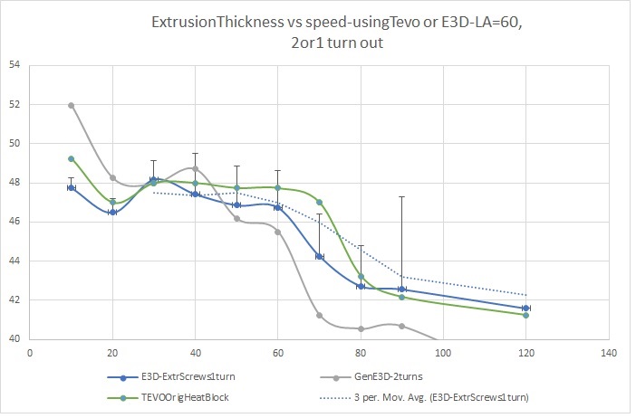
Many clever people commenting here - just want to add an observation and a test anyone can run.
I was trying to find out what is the maximum speed of my printer's extrusion, and developed this test of measuring extrusion width at various speeds. Was surprised to see the results were not linear up to a point, but degraded from 10mm/s to 120mm/s.
Strangely my upgrade to genuine E3D did not help. Tightening the extruder pressure screws had improvement. Its now understood why corners have too much material in them.
Ive been thinking for ages that some fudge factor is needed. Keen to try this M592
I tried to fix this using linear advance v1.1 without much improvement.
Looking forward to the release of LA 1.5 !
 SimonSolar2C
on 17 Mar 2018
SimonSolar2C
on 17 Mar 2018
Here's some real world data and a simple method to calibrate/check that should further prove the utility of this feature. I measured the amount of 1.75mm PLA filament actually extruded on an Ender 3 at various extrusion speeds (on the extruder side!) when the hotend is at 210C (at which I get good adhesion and barely any strings). I'm using a stock Ender 3 calibrated earlier at 95 Esteps / mm and marking the filament at 130mm away from the extruder, sending the G92 E0; G1 E100 Fspeed command to extrude 100mm then measuring the distance to the filament mark I made earlier (as is done in usual extruder / ESteps calibration guides). Meanwhile I'm checking that the extruder gear doesn't skip (it didn't seem to). I've tried to be as consistent as possible including around timing which affects amount of oozing.
The speed I've selected to test reflect my real world testing: 30, 40, 60, 80, 100, 120 mm/min which, if you do the math, correspond to printing at roughly 15mm/s to 60mm/s with 0.2mm layers, 0.4mm nozzle/width and 1.75mm filament (area of filament * 30mm/min is about 0.2*0.4 * 15mm/s). The lower bound comes from my configured jerk of 15mm/s (since 20mm/s jerk results in ringing from X axis even after adjusting belt tightness, though Y axis was fine, go figure).
Requesting extruding 100mm, I get at:
30mm/min | 99.63mm
40mm/min | 99.51mm
60mm/min | 99.05mm
80mm/min | 98.40mm
100mm/min | 97.96mm
120mm/min | 97.40mm
(Note that while I've used a precision caliper and tried to be consistent, I'm sure there were measuring errors)
This partly explains the weird combination of over-extruding (small walls on full bottom layers) and under-extruding (larger inner walls at 50mm/s) I've gotten in my test prints.
Even a simple "extrude 0.00025 * speed more per mm" would bring down the extrusion errors from 2% to 5-10x less and allow for a later good extrusion rate/flow calibration (set in the slicer).
Final note: I believe I'm getting more linear like results than SimonSolar2C since there are fewer variables at play in my test setup than in theirs.
 mihai-dumitresq
on 14 Feb 2019
mihai-dumitresq
on 14 Feb 2019
Someone in this thread mentioned that the cause of the issue is unknown. Well, in http://www.extrudable.me/2013/04/18/exploring-extrusion-variability-and-limits/ a photo is provided which shows that the teeth marks get closer when the filament is pushed faster.
In other words the nonlinear extrusion is the result of plastic deformation of the filament.
 dewi-ny-je
on 12 Jul 2020
dewi-ny-je
on 12 Jul 2020
shows that the teeth marks get closer when the filament is pushed faster
It's my understanding that the springiness of the filament and the increased back-pressure of faster motion causes a more pronounced spring back (or slippage) as the filament is pushed at a faster rate. You can test this theory by instead lowering the hotend temperature so that the filament is harder to push, and you should see the same symptom, with the tooth-marks getting closer together as the temperature gets lower.
thinkyhead
on 20 Jul 2020
Guys, I came across this thread and I decided I wanted to add nonlinear extrusion to Marlin and do some real world testing. Maybe I will make a PR if it works well. My goal is transparently supporting M592 in the same way as Duet
I am halfway there, I have added the M592 command to the command parser, and Im comfortable enough in C++ to find a place to store the parameters and stuff (I am also looking at the Duet3D RepRap firmware code which is also on Github, and the command parser is similar, so its pretty easy)
But I need to know exactly where in the Marlin code to tie the nonlinear extrusion values into the extruder speed. The movement planner looks kind of complex. Im afraid I'm going to break my printer with a ridiculous movement.
It should be a really simple addition, in Duet3d it is only a few lines. I was hoping some guru could just point me to the exact spot. For reference in Duet3D it does this (just to show how easy it should be)
#if SUPPORT_NONLINEAR_EXTRUSION
    // Add the nonlinear extrusion correction to totalExtrusion
    if (dda.flags.isPrintingMove)
    {
        float a, b, limit;
        if (reprap.GetPlatform().GetExtrusionCoefficients(extruder, a, b, limit))
        {
            const float averageExtrusionSpeed = (extrusionRequired * StepTimer::StepClockRate)/dda.clocksNeeded;
            const float factor = 1.0 + min<float>((averageExtrusionSpeed * a) + (averageExtrusionSpeed * averageExtrusionSpeed * b), limit);
            extrusionRequired *= factor;
        }
    }
#endif
I am working from the 1.1.9 marlin code.
 timmeh87
on 27 Aug 2020
timmeh87
on 27 Aug 2020
Related issues
 Glod76
·
3Comments
Glod76
·
3Comments
 Ciev
·
3Comments
Ciev
·
3Comments
 heming3501
·
4Comments
heming3501
·
4Comments
 ceturan
·
4Comments
ceturan
·
4Comments
 Tamonir
·
3Comments
Tamonir
·
3Comments
Most helpful comment
Hmm, so that's a small difference, but still significant. A 2% reduction in mass at double the speed. I find it mildly amusing that the solution is to feed more into the extruder, thus increasing the pressure even more. But, it is perfectly sensible to mitigate against this effect nevertheless.
I'll see about adding
M592and borrow the formula given on reprap wiki: