Marlin: [FR] Print resume after power outage
Hello. Can you add a code that constantly checks the voltage during the printing with so called "secret voltmeter" in atmega and when it drops down write the printing file line number OR position of X,Y,Z to EEPROM or/and SD card. You can also try to send some Gcode(i'm not a Gcode guru, may be some custom Gcode needed) for Octoprint to signal about the power outage + move Z axis away from the printing object. Sleep mode can be used to save some charge.
More information: https://www.youtube.com/watch?v=G6dvDgCOyqk
Code example(including 2560):
http://www.instructables.com/id/Secret-Arduino-Voltmeter/
https://code.google.com/archive/p/tinkerit/wikis/SecretVoltmeter.wiki - 328 & 168
Thank you!
 anton-piliugin
All 18 comments
Duplicate of #2085 ?
 Grogyan
on 26 Feb 2018
Grogyan
on 26 Feb 2018
Duplicate of #2085
 thinkyhead
on 26 Feb 2018
thinkyhead
on 26 Feb 2018
The new aspect here was the detection of the power outage without additional hardware.
Tried it.
Flashed
void setup() {
  // set the reference to Vcc and the measurement to the internal 1.1V reference
  #if defined(__AVR_ATmega32U4__) || defined(__AVR_ATmega1280__) || defined(__AVR_ATmega2560__)
    ADMUX = _BV(REFS0) | _BV(MUX4) | _BV(MUX3) | _BV(MUX2) | _BV(MUX1);
  #elif defined (__AVR_ATtiny24__) || defined(__AVR_ATtiny44__) || defined(__AVR_ATtiny84__)
    ADMUX = _BV(MUX5) | _BV(MUX0) ;
  #else
    ADMUX = _BV(REFS0) | _BV(MUX3) | _BV(MUX2) | _BV(MUX1);
  #endif

  DDRB = 0xFF;
}

void loop() {
  while (1){
  static uint8_t togle = 0;
  // Read 1.1V reference against AVcc
  ADCSRA |= _BV(ADSC); // Start conversion
  while (ADCSRA & _BV(ADSC))  // while conversion runs
    digitalWrite(53, (togle++ & 1)); // pin 53 is port B bit 0

  uint8_t result  = ADCL >> 2; // must read ADCL first - it then locks ADCH
  result |= ADCH << 6; // unlocks both
  PORTB = result;
  }
}
in a naked Arduino Mega clone.
Connected my logic analyser and
pulled the USB cable.
PowerOutage.logicdata.txt
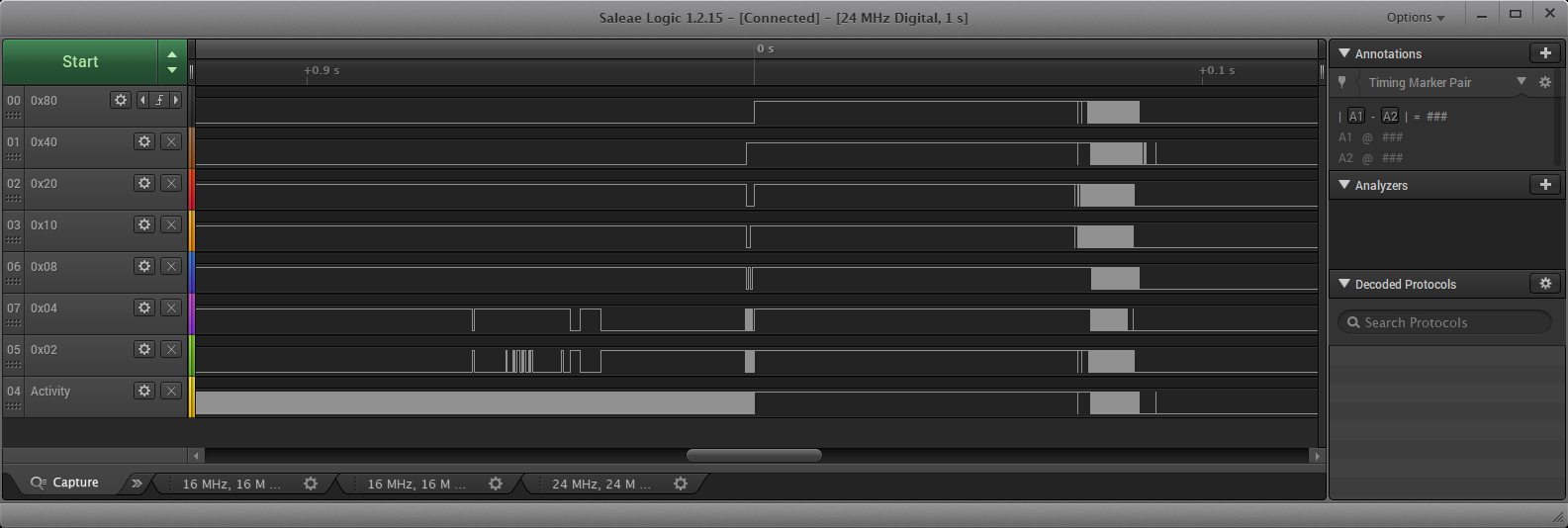
What you see is program execution until 0s. A bit of noise on the low digits. The power outage at about 0s. Randomly flickering bits when the processor dies around 0.07s to 0.09s.
Enlarging around 0s
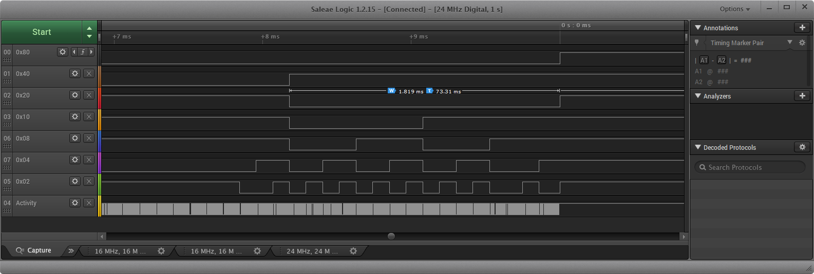
shows:
- a reliable detection is possible from about 1.8ms before the msb goes high
- msb indicates the external voltage is now only 2 times larger than the internal 1.1V reference, so about 2.2V
- 2.2V is below the threshold for the brown out detection set at 2.7V (2.5 - 2.9)
- at 0s the processor gets a brown out reset. Execution stops.
An additional 1000µF capacity between GND and VCC did not alter the times considerably.
Conclusion:
Nice idea, but less than 2ms is not enough to do something useful.
 AnHardt
on 28 Feb 2018
AnHardt
on 28 Feb 2018
Can you test the same on CR-10 or CR-10S or any other atmega based printer? Because this solution may have different behaviour on a real board. Thank you for your time anyway!
How do you connect your atmega clone? Do you use a PSU?
anton-piliugin
on 28 Feb 2018
You still require external hardware to detect an outage.
The purpose of reference voltages is to give better accuracy of the internal ADCs, or provide an offset voltage for the internal ADCs
Even using external hardware attached to the External Reference to try and detect power loss, will end up changing your ADC values.
Grogyan
on 28 Feb 2018
Also if someone else would like to test this solution, please do it on a real printer not on a naked board and don't use power off button on a control box, better to just unplug the control box. Try to recreate the real power outage(x,y,z movement) situation and thanks to anyone who is trying to test it!
anton-piliugin
on 28 Feb 2018
@anton-piliugin In a real power outage situation, you NEED to detect loss of power before voltage drop is detected on the micro.
If to use the internal reference as a detector, which is used for the internal ADCs which are in turn used for measuring things like the hot end temperature, is a bad idea.
As stated the ability to be able to internally measure the internal reference voltage is usually used as a feedback mechanism to ensure ADC stability, or offset requirement, or calculation that requires knowing what the reference is if it changes.
Please see Josef's comments on the Prusa I3 MK3 on his forum, and youtube videos. He has the detector at exactly the point in the whole system where it needs to be.
Grogyan
on 28 Feb 2018
@Grogyan Do you know that CR-10 mini, CR-10 S4 and S5 has this feature by default without any detectors?
anton-piliugin
on 28 Feb 2018
@anton-piliugin Can you please point me to where I can find schematics for said printers?
It is quite probable they do have a detector, but it is onboard. Hopefully not from the 12/24V output.
Grogyan
on 28 Feb 2018
@Grogyan The board should have some pins or connectors for this detector, right? You can google a picture of this mainboards, for example:
https://www.th3dstudio.com/knowledge-base/creality-cr-10-and-cr-10s-models-what-printer-do-you-have/
anton-piliugin
on 28 Feb 2018
Photos aren't accurate, and show old versions of this board.
As I work with consumer electronics, I would need a schematic to prove that the printers you have suggested are using the internal/external VREF for detection.
However as the Creality printers are made to be as cheap as possible, if they do use the internal VREF, this raises alarm bells for me.
Grogyan
on 28 Feb 2018
Reddit and maker SexyCyborg managed to get a copy of the source code, so time to read through the code to see what they did, keep in mind that the source code could be for an old version, and may not support their newest features.
Grogyan
on 28 Feb 2018
Reddit and maker SexyCyborg managed to get a copy of the source code
Good news. As a CR-10S owner I will still be requesting the source code from Creality3D — to find out if they are at all compliant with the GPL. But it's great to have the sources in the meantime.
thinkyhead
on 28 Feb 2018
@anton-piliugin
Can you test the same on CR-10 or CR-10S
Sorry no hardware here.
or any other atmega based printer?
Sory. They are in use and have not any free pin.
You could do it yourself. Slow LAs are below 4€ now, but totally sufficient for the snail 16MHz AVRs. Search for "USB 24MHz 8CH Logic Analysator".
All the Creality boards have a inductivity on board. I assume for making 5V from 12V. With a simple voltage divider or even better a Schmidt trigger between that and the AVR they could measure a drop in the 12V circuit. That would not need an additional connector. The detection could be early enough to detect the outage, not in time to move away, but to save something.
AnHardt
on 28 Feb 2018
I can't test it right now, because i just bought a printer and my order on GB is still in process. Analysator is good, but the blind test using the code and the algorithm(https://github.com/MarlinFirmware/Marlin/issues/2085#issuecomment-368703417) may be better
anton-piliugin
on 1 Mar 2018
After looking through the code from Creality, they appear to be using the same code for detection, saving gcode, and resuming, as the WASP Project in #2085
Grogyan
on 1 Mar 2018
using the same code for detection, saving gcode, and resuming as the WASP Project
😮
thinkyhead
on 1 Mar 2018
At first i tried the original code. It never showed something useful. It either showed full voltage or not running at all. Reason was the 2ms (delay(2);) in the original code. Everything of interest happened during this delay. So i had to speed up the test a little. :-)
AnHardt
on 1 Mar 2018
Related issues
 StefanBruens
·
4Comments
StefanBruens
·
4Comments
 Bobsta6
·
3Comments
Bobsta6
·
3Comments
 W8KDB
·
4Comments
W8KDB
·
4Comments
 ceturan
·
4Comments
ceturan
·
4Comments
 Ciev
·
3Comments
Ciev
·
3Comments
Most helpful comment
Good news. As a CR-10S owner I will still be requesting the source code from Creality3D — to find out if they are at all compliant with the GPL. But it's great to have the sources in the meantime.