Marlin: MKS Gen 1.4 + Anet A6 LCD dont work
Hi all!
The Anet A6 LCD doesnt work on the MKS Gen 1.4.
I used this Datasheet to connect the LCD with own cables, but doesnt help.
Settings set:
#define DOGLCD
#define REVERSE_MENU_DIRECTION
#define SPEAKER
#define LCD_FEEDBACK_FREQUENCY_DURATION_MS 100
#define LCD_FEEDBACK_FREQUENCY_HZ 1000
#define REPRAP_DISCOUNT_FULL_GRAPHIC_SMART_CONTROLLER
Hardware:
 TiToMoskito
All 41 comments
@Rexima
000-README_RepRap_Discount_Full_Graphic_Smart_Controller.txt
The MKS products (all?) have the EXP1 & EXP2 LCD connectors rotated 180 degrees from the ones on the RepRap LCD controllers.
In order to attach the RepRap Discount Full Graphic Smart Controller you'll need to do something like one of the following for both EXP1 & EXP2:
a. On one end only, shave the keying plug off the cables and plug the cables in backwards.
b. On one end only, carefully pry the housings off the board, rotate them 180 degrees and press them back onto the pins.
c. Make custom cables where one connector is rotated 180 degrees.
MKS: 1 2 3 4 5 6 7 8 9 10
RepRap: 10 9 8 7 6 5 4 3 2 1
 cjsoong
on 29 Jan 2018
cjsoong
on 29 Jan 2018
Doesnt work either :(
I tried it like this, i took one end, and rotated it 180 degrees and plugged it in, on both connections.
- No backlight, nothing happened.
Than i followed this picture and rotated it also 180 degrees:
- Backlight is working
- The buzzer is yelling (maybe because the board is only powered through USB?)
- The SW1 Button/Stick, seems to be recognized. If i use the stick, a blue led on the board is turning on.
- Nothing appears on the screen, just flickering (maybe USB too)
This is my Configuration, maybe something wrong here?
Configuration.txt
TiToMoskito
on 29 Jan 2018
@Rexima
Your wiring should be wrong
Can refer to "marlin source code : pin_anet_10.h"
cjsoong
on 29 Jan 2018
@cjsoong Thank you very much, i just took a look at pins_ANET_10.h and followed the table and tried to pin it like in this column "RepRapDiscount Full Graphics Display Wiring"
And i see in a small area on the left top side, a little bit text.
What works:
- Reset Button
- Menu Navigation Button
- Beeper when going into menu
What not works:
- Display
I made some screenshots:
TiToMoskito
on 29 Jan 2018
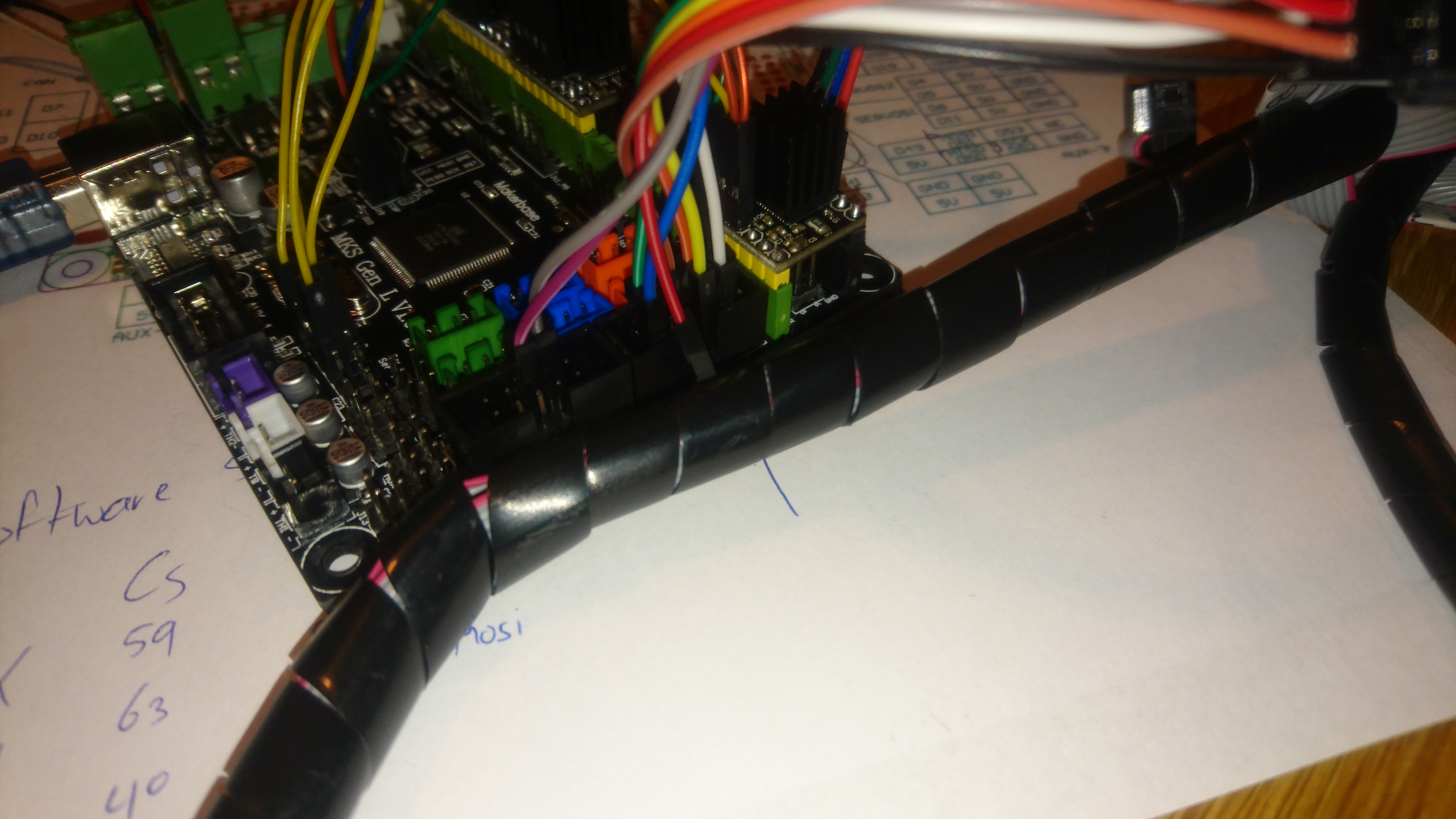
Thats my wire setup: https://i.imgur.com/JN6EZse.png
And this is my current config: https://pastebin.com/MN7wQG4K
TiToMoskito
on 29 Jan 2018
@Rexima
try modify ultralcd_impl_DOGM.h :
#elif ENABLED(U8GLIB_ST7920)
  //U8GLIB_ST7920_128X64_4X u8g(LCD_PINS_D4, LCD_PINS_ENABLE, LCD_PINS_RS); // Original u8glib device. 2 stripes
                                                                            // No 4 stripe device available from u8glib.
  U8GLIB_ST7920_128X64_1X u8g(LCD_PINS_D4, LCD_PINS_ENABLE, LCD_PINS_RS);    // Original u8glib device. 8 stripes
//  U8GLIB_ST7920_128X64_RRD u8g(0); // Number of stripes can be adjusted in ultralcd_st7920_u8glib_rrd.h with PAGE_HEIGHT
Tried this happened: Picture
After 1 minute it disappeared and its like now as before. (Images above)
TiToMoskito
on 30 Jan 2018
@Rexima
Can you confirm that these 5 lines are connected correctly?
Also test #define MOTHERBOARD 33 or MKS_BASE
                  exp1
                      . .
LCD_DE-->. .--->LCD_RS
LCD_D4-->. .
                 . .
        GND-->. .--> +5V
I pulled all cables off and than back again, nothing changes, also the motherboard defines doesnt take any effect...
TiToMoskito
on 30 Jan 2018
@Rexima
I really can not think of other reasons, maybe you should buy a "RepRapDiscount Full Graphics Display"
cjsoong
on 2 Feb 2018
Be sure to ask for help from other Anet A6 users at http://forums.reprap.org/index.php
 thinkyhead
on 17 Feb 2018
thinkyhead
on 17 Feb 2018
Very nice, @SrMarron. Thanks for the info!
thinkyhead
on 18 Mar 2018
Hmm... I'm having a similar issue. I've created my adaptor cable as specified by @SrMarron. I'd already checked whether this all worked with the RepRap Full Graphic Smart Controller first... Now I want to get it going with the A6 display since the enclosure is already in place.
I've double checked connections now and am 100% confident it's wired as specified. I just used jumpers to test instead of soldering - i'm glad I did!
I have defined
define ANET_FULL_GRAPHICS_LCD // which gets redefined to reprap full graphics display
define BOARD_RAMPS_14_EFB // and tried MOTHERBOARD BOARD_MKS_GEN_L
But nothing else. I haven't redefined any pin mappings - I don't think I need to do this from what I've seen so far.
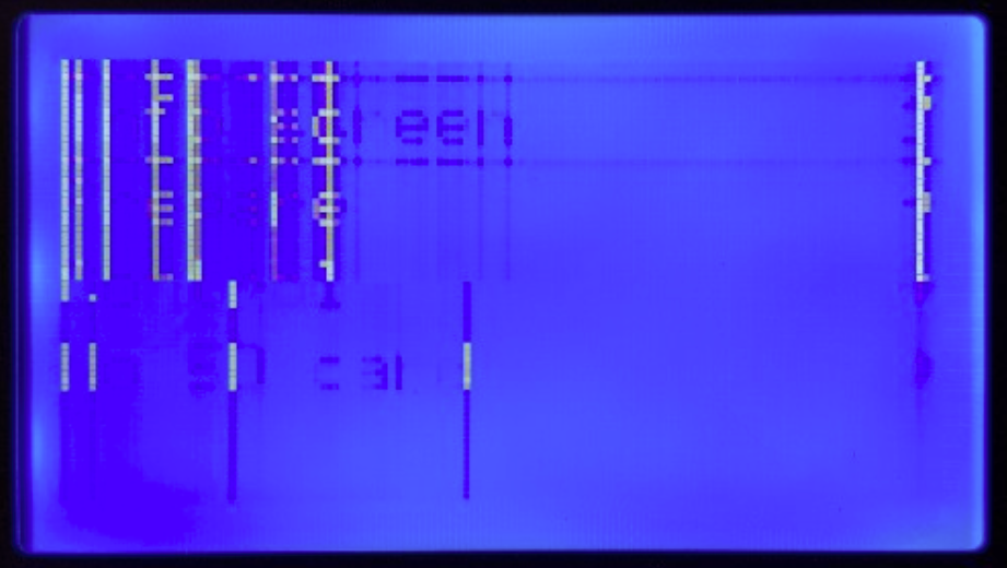
Anyway, I get the following 'corrupt' display. It's partially correct...ish. The Fan icon updates, yet is still graphically messed up.
I'm very open to suggestions please. Thanks


 dfcw
on 22 Apr 2018
dfcw
on 22 Apr 2018
Okay, I triple checked and re-wired as per pins_ANET_10.h @thinkyhead @cjsoong
As someone that works in an embedded software/electronics industry I'm starting to get annoyed with myself that I can't work this out... 😀
So, I think I've confirmed as much as possible that the suggest wiring is correct - different sources, same result. It's unlikley to be a board specific fault as before connecting the Anet 12864 display I first checked everything worked using the RepRap Full Graphics display.
It's so close! The screen is updating, the menu is working... I can see ghosted text on the screen. I'm not sure how these screens work specifically but I'm not sure how aspects are 'faint' as these displays aren't gray-scale. Either there are invalid commands (unlikely, it would have been seen already) or the pin-out from the MKS is so subtly wrong yet right enough for it to partially work... Or, since these are SPI, then the transfer rate or clock could be out of sync. I tried slowing down the clock to eighth speed with no change to the behaviour.
Any help much appreciated please!
This is the menu after clicking the encoder. You can see the beginnings of "Info Screen"

dfcw
on 23 Apr 2018
@dfcw — What version of Marlin are you using?
thinkyhead
on 23 Apr 2018
@thinkyhead 1.1.8
dfcw
on 23 Apr 2018
@thinkyhead have there been any code changes relating to areas that might affect this in the bugfix builds? It seemed like folks had this going using the stable build... Thanks
dfcw
on 23 Apr 2018
There have been a lot of fixes since 1.1.8. I definitely recommend taking bugfix-1.1.x for a spin.
thinkyhead
on 26 Apr 2018
@thinkyhead Giday mate. I'll do that. I've got the 1.1.x bugfix running at the moment but the discount reprap display is sitting loose on the bench... I'm keen to use the original UI so I'll try the anet display again over the weekend. Thanks
dfcw
on 26 Apr 2018
@thinkyhead Giday again. Okay, I tried wiring up again using bugfix-1.1.x with the same results. Bugger :( I was really hoping I could get the Anet A6 display working! It's a bit bizzare that other people have had success, yet it's not working for me. I get exactly the same display issues as identified above.
dfcw
on 28 Apr 2018
I've no idea what to tell you. You can only keep messing with the pins, the signal delays…
#define ST7920_DELAY_1 DELAY_0_NOP
#define ST7920_DELAY_2 DELAY_0_NOP
#define ST7920_DELAY_3 DELAY_0_NOP
…and the LCD selection items in ultralcd_impl_DOGM.h…
#else
  // for regular DOGM128 display with HW-SPI
    //U8GLIB_DOGM128 u8g(DOGLCD_CS, DOGLCD_A0);  // HW-SPI Com: CS, A0  // 8 stripes
    U8GLIB_DOGM128_2X u8g(DOGLCD_CS, DOGLCD_A0);  // HW-SPI Com: CS, A0 // 4 stripes
#endif
…until you hit on some combination that works.
thinkyhead
on 29 Apr 2018
@thinkyhead Thanks mate! That's enough for me to work with... omg... I don't know how anyone uses the Arduino IDE. It's bloody horrible, and makes code navigation/learning a nightmare. I guess I should have created a VS/Eclipse version of the project to make navigation/searching easier.
My gut feel is that the pin-outs were correct, and it's as aspect of the lcd configuration/setup that's wrong - your snippets give me some places to start testing. Thank you.
Someone else had commented about switching D4 and Enable - not sure what happened to that comment. I'll take a look though. After switching to the MKS setup, along with converting to a bowden arrangement I'm having issues far greater than the LCD now - should have stuck with direct drive I think! :) Thanks, i'll be sure to update the thread if I find an answer.
dfcw
on 29 Apr 2018
Oh yeah, we sure don’t use the IDE as our editor, just for building (when not using PlatformIO in Visual Studio Code or Atom). I personally only use Sublime Text 3 for all my coding because it’s so lightweight and responsive. It also has a plugin for building with PlatformIO but it’s not as fully integrated as with the other editors I mentioned. I’d love to switch to VSCode full time, but it’s just too bulky. So I just use it for building.
thinkyhead
on 30 Apr 2018
@thinkyhead Right, I've spent a couple of lunchtimes looking at that now and have got VS Code + Arduino all sorted. It's an interesting IDE... I'm use to working using a combination of Rowley/IAR and Visual Studio Pro.
The bit i'm a touch confused on is the use of the term 'stripes'. I've done a lot of work with LCDs but have never encountered that term...
- Number of lines of text?
- Width of data bus?
- Height of each row/page?
Even google hasn't helped me out with that one... My first guess is that it refers to bus/interface width, but then it also goes on to say that the number of stripes can be derived from page height - so it's like it's referring to the number of pixels in each row, or the number of rows on the display. Even searching for LCD datasheets using the term is coming up with slim results :-) Thanks
dfcw
on 2 May 2018
DOGM graphical displays can be updated all at once, but it takes a long time to send 16 bytes times 64 lines (1K) of data over SPI, which is usually blocking software-based SPI. So the U8G library provides the option to update only part of the display (which it calls a "page" or "stripe") on each loop of the program. This way the display update function blocks for much less time. But it also means that you can sometimes see one part of the display update before the next part updates, especially when printing at high speed. And, it means that anything we print or draw on the screen that sits on the border of two (or more) stripes has to be drawn two (or more) times. The library clips whatever is drawn or printed to within the current stripe.
thinkyhead
on 4 May 2018
Okay, so it's an arbitrary term used to describe the process of breaking up the screen buffer in to chunks... that makes way more sense. I'm sitting here thinking that seems so inefficient... then after checking the datasheet remembered that these guys don't even have FIFO's, let alone the DMA's I've been using for the last decade (stm32's). Then looking at the ST7920, it can only handle approx half a Mbit data transfer... with a tight enough loop, it should still be possible to clock out the 128x8 bytes in around 2ms - but this is where clock domains and other peripherals start to be affected - and is definitely now off topic :-) Actually, rechecking, at 72us per write, it's around 74ms... seriously? I guess the design is pre-2000 so it's not entirely surprising :-) Oh well... The down-sides of working with old-tech!
Thanks. I need to get my A6 up and running again after a failed bowden conversion, then have another go at getting the A6 display going. Cheers
dfcw
on 6 May 2018
Any progress since ? You should really be using Visual Studio Code for building & compiling - saves lots of time.
 saikek
on 21 May 2018
saikek
on 21 May 2018
Switching cable millions of time caused my LCD left top part to malfunction.
That's what i've noticed when connected it to old motherboard
saikek
on 21 May 2018
@saikek Giday mate, I got VS Code set up at work, but rarely find myself with enough time at home... it probably took me about 90 minutes to trial and error my way through to successful compiles. It's definitely a much nicer IDE though... I use VS and CrossStudio (Rowley) as my daily IDE's so it's much closer to what I'm use to working with. I keep finding excuses not to install it if I'm just making simple changes...
But, my plan is to try and make time this weekend to have another go with the A6 display... I've found a few other options to change.
dfcw
on 22 May 2018
@dfcw And which motherboard you were using before MKS GEN 1.4 ?
I've found plenty of things that needs to be changed (Z-direction, E-direction), endstops are not working.
... And i haven't yet played with drivers.
I'm thinking more and more that it would be much less struggle to connect 2004 display - but my 2 attempts with pin's editing were not succesfull.
saikek
on 23 May 2018
@saikek I'd been using the Anet 1.0 board. Yeah, there's a fair bit to change around but it's all quite straight forward.
@thinkyhead I pulled out my scope (old 4 channel) and checked SPI timing which all appeared fine and within spec (checking supplies and logic levels). I also rolled back (with a bit of effort) to RC4 and RC8 to see if the display worked with those versions (which it didn't). This whole time, the visual on-screen symptoms have essentially been identical. Partial text, partial menus, and partial icons, but all a bit corrupted and faint. I've checked wiring against three different sources so I'm quite confident that's not the issue - to the point of going from uC pins through to LCD pins, as opposed to using just connector pin numbering.
Is there possible a difference in command sequencing with these displays? It's got me bloody stumped since more than a few people seem to have success... so for hte life of me I can't work out what the differences are.
Changing the timing, and number of stripes made no noticeable difference in output. I've left my gear set up so if you've got suggestions on what to try I can do that fairly easy now.
Cheers!
dfcw
on 26 May 2018
If you could get an identical (but new) display to test, and if it showed the same problem, that would tend to confirm that there's a firmware issue. At this point it does sound like a problem with the unit, especially given the "faint" aspect.
thinkyhead
on 26 May 2018
@thinkyhead The best I've been able to do is verify it's working fine by plugging it back in to the original Anet 1.0 MB and checked that it's working correctly. I don't know anyone else with one of these unfortunately.
FAAARRRKKK... I thought I should probably just make 100% sure before making that claim. I'll just reconnect it to the original Anet MB... which to be fair, is now running Marlin though - but it isn't working there either.
So, I think I'm just going to give up on this. Unless I can get another Anet A6 display to help locate where the problem is (or the original A6 firmware for the MB) then I'm just wasting everyone's time. Still, it's been an educational experience :-) I work with brushless DC motors at work on robotics, but had never played with gcode, so this has all been bloody interesting :) Thanks for helping narrow it down...
dfcw
on 26 May 2018
FWIW, I followed the steps at https://www.thingiverse.com/groups/anet-a6/forums/general/topic:27555#comment-1791018 and it is working straight ahead with the latest 2.0 bugfix.


 jjansen85
on 18 Dec 2018
jjansen85
on 18 Dec 2018
No No No
this is right way:


 daimiao
on 19 Dec 2018
daimiao
on 19 Dec 2018
That is not a Anet LCD. Pin connection on A-net LCD is different.
jjansen85
on 19 Dec 2018
Fixed, this works on an Anet LCD from an E12 control box.
https://www.instructables.com/id/Using-an-Anet-Full-Graphics-Display-on-a-MKS-Gen-1/
 NAPCAL
on 8 Feb 2019
NAPCAL
on 8 Feb 2019
Fixed, this works on an Anet LCD from an E12 control box.
https://www.instructables.com/id/Using-an-Anet-Full-Graphics-Display-on-a-MKS-Gen-1/
Thanks, nice work!
jjansen85
on 10 Feb 2019
@Rexima Please post your question either on discord: https://discord.gg/n5NJ59y or on facebook: https://www.facebook.com/groups/2080308602206119/
The issue list is for bugs and feature requests only
Please close this issue once you have posted it on one of the 2 links
Thanks :-D
 boelle
on 20 Feb 2019
boelle
on 20 Feb 2019
@thinkyhead Another one that needs to be closed. Sorry, I got bored.
boelle
on 22 Jun 2019
This issue has been automatically locked since there has not been any recent activity after it was closed. Please open a new issue for related bugs.
![github-actions[bot] picture](https://avatars2.githubusercontent.com/in/15368?v=4&s=40) github-actions[bot]
on 5 Jul 2020
github-actions[bot]
on 5 Jul 2020
Related issues
 jerryerry
·
4Comments
jerryerry
·
4Comments
 esenapaj
·
3Comments
esenapaj
·
3Comments
 Bobsta6
·
3Comments
Bobsta6
·
3Comments
 ahsnuet09
·
3Comments
ahsnuet09
·
3Comments
 W8KDB
·
4Comments
W8KDB
·
4Comments