Marlin: Issue Connecting MKS MINI 12864 with RUMBA
So i tried connecting an MKS MINI 12864 to my RUMBA board, using Marlin 1.1.6 and defining the lcd in my configuration file like this:
Configuration.h
board ***
// SERIAL_PORT selects which serial port should be used for communication with the host.
// This allows the connection of wireless adapters (for instance) to non-default port pins.
// Serial port 0 is still used by the Arduino bootloader regardless of this setting.
#define SERIAL_PORT 0

// This determines the communication speed of the printer
#define BAUDRATE 250000

// This enables the serial port associated to the Bluetooth interface
//#define BTENABLED              // Enable BT interface on AT90USB devices

// The following define selects which electronics board you have.
// Please choose the name from boards.h that matches your setup
#ifndef MOTHERBOARD
  #define MOTHERBOARD 80
#endif
** lcd ***
//
// Makeboard 3D Printer Parts 3D Printer Mini Display 1602 Mini Controller
// https://www.aliexpress.com/item/Micromake-Makeboard-3D-Printer-Parts-3D-Printer-Mini-Display-1602-Mini-Controller-Compatible-with-Ramps-1/32765887917.html
//
//#define MAKEBOARD_MINI_2_LINE_DISPLAY_1602

//
// MKS MINI12864 with graphic controller and SD support
// http://reprap.org/wiki/MKS_MINI_12864
//
#define MKS_MINI_12864

//
// Factory display for Creality CR-10
// https://www.aliexpress.com/item/Universal-LCD-12864-3D-Printer-Display-Screen-With-Encoder-For-CR-10-CR-7-Model/32833148327.html
//
// This is RAMPS-compatible using a single 10-pin connector.
// (For CR-10 owners who want to replace the Melzi Creality board but retain the display)
//
//#define CR10_STOCKDISPLAY
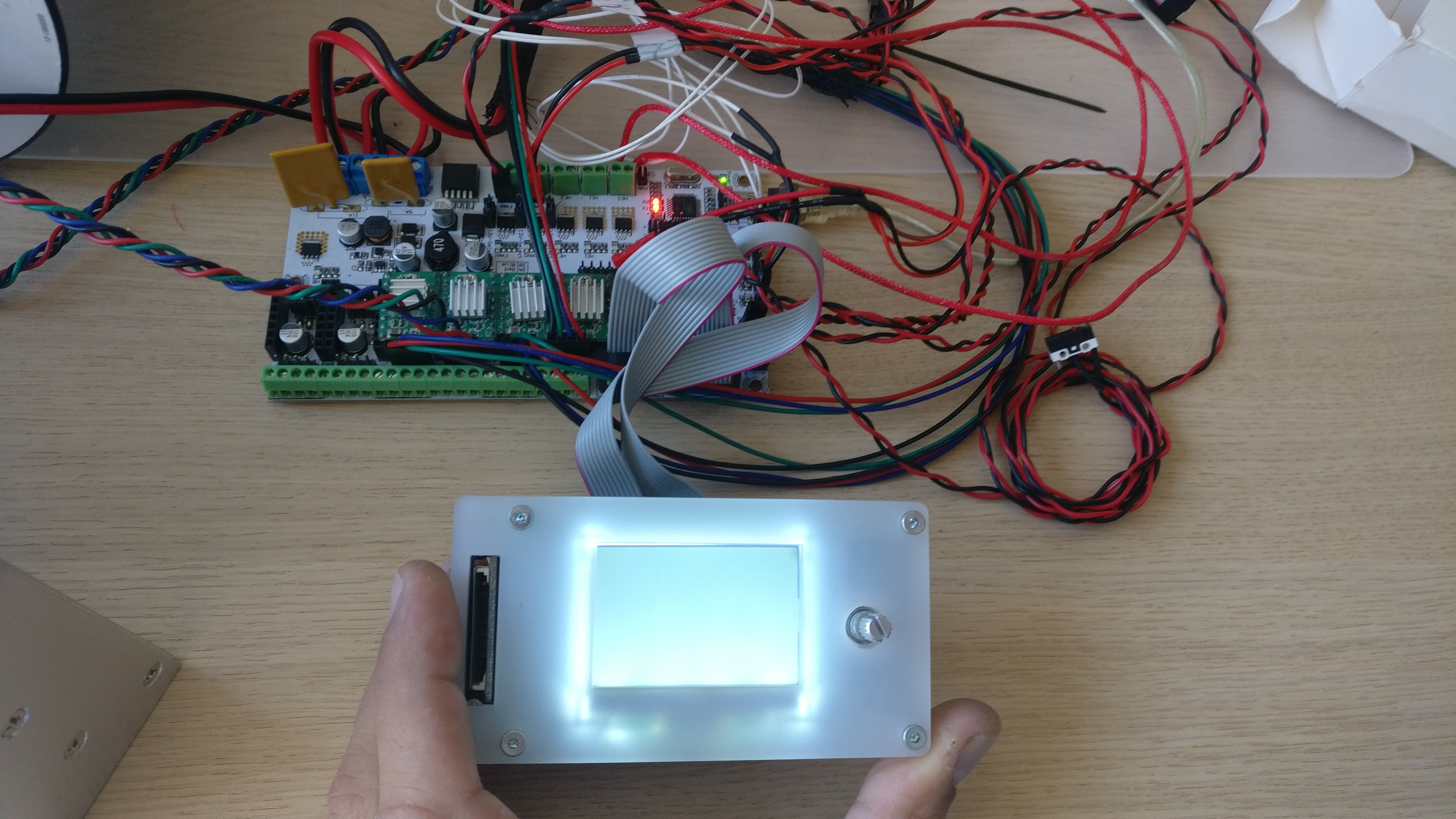
And all i got was backlight like in the picture below.
After that I began trying diferent combinations with boards that I had around and I manage to make all the different combinations below:
1 - MKS mini v1.2 programmed as Rumba board

2- MKS mini v1.2 programmed as an MKS board

3- Ramps 1.4 programmed as Rumba
4- Ramps 1.4 programmed as Ramps
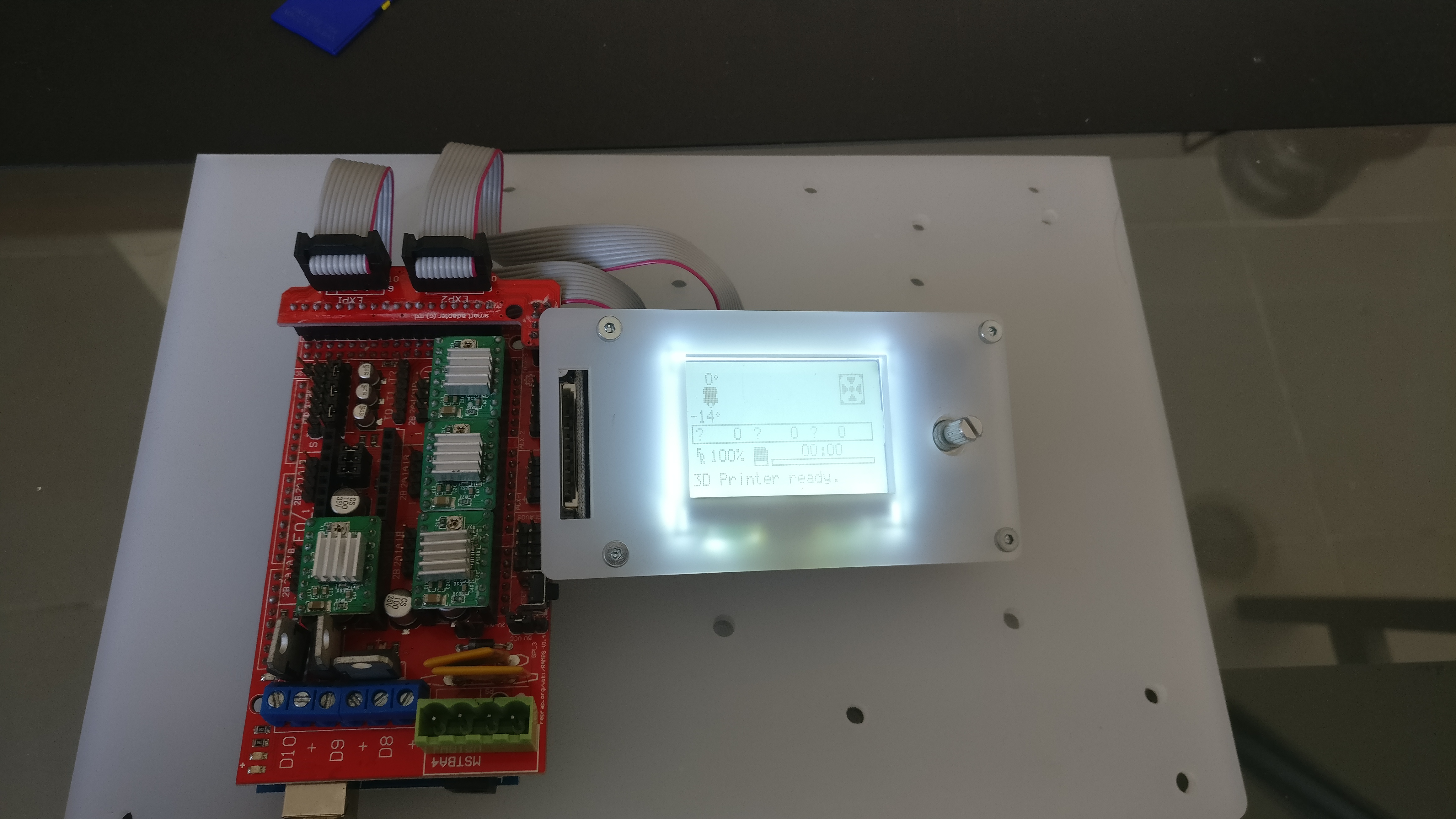
All worked fine, detecting if the SD was inserted and everything.
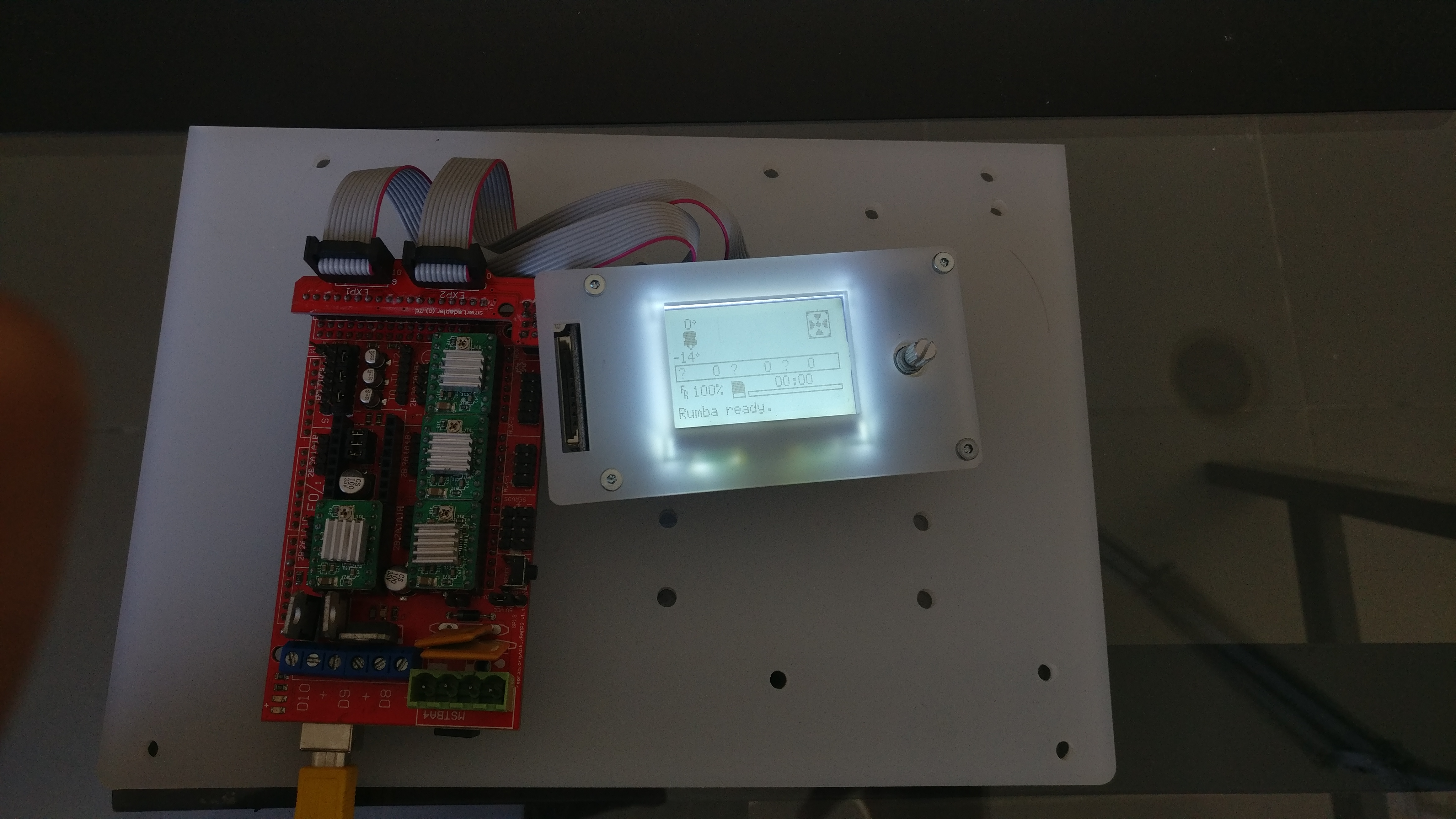
I tried all combinations of EXP1 and EXP2 between the LCD and the board RUMBA and the best I managed to get was the backlight on and some residual image like in the picture below:

I think this is a PIN definition problem but I can't find which ones. If someone could take a look at this that's would be great.
Thank you for your attention and sorry for the long post but I thought it would more useful this way
 BlocksTechnology
All 4 comments
The last picture looks more like a timing problem than a pin problem.
// If you want you can define your own set of delays in Configuration.h
//#define ST7920_DELAY_1 DELAY_0_NOP
//#define ST7920_DELAY_2 DELAY_0_NOP
//#define ST7920_DELAY_3 DELAY_0_NOP
 AnHardt
on 20 Nov 2017
AnHardt
on 20 Nov 2017
AnHardt thanks for the reply, I tried uncommenting those defines and it still shows the same problem as before. Any idea which value should I put in each delay?
BlocksTechnology
on 20 Nov 2017
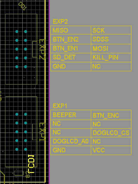
Below is the MKS MINI 12864 pinout and the Rumba schematic.
If the SD card is working properly then it has to be DOGLCD_A0 and/or DOGLCD_CS that has the problem. Try adding the following defines:
#define DOGLCD_CS        38
#define DOGLCD_A0        41

 Bob-the-Kuhn
on 20 Nov 2017
Bob-the-Kuhn
on 20 Nov 2017
Thank you Bob-the-Kuhn! It's working fine now.
BlocksTechnology
on 21 Nov 2017
Related issues
 Bobsta6
·
3Comments
Bobsta6
·
3Comments
 otisczech
·
3Comments
otisczech
·
3Comments
 StefanBruens
·
4Comments
StefanBruens
·
4Comments
 Glod76
·
3Comments
Glod76
·
3Comments
 jerryerry
·
4Comments
jerryerry
·
4Comments
Most helpful comment
Below is the MKS MINI 12864 pinout and the Rumba schematic.
If the SD card is working properly then it has to be DOGLCD_A0 and/or DOGLCD_CS that has the problem. Try adding the following defines: