Marlin: USB Serial port Configuration.h error
Bug Report
- Description: ---
I cannot connect to Sbase via usb serial Pronterface with example Sbase settings.
So the solution is:
On MKS Sbase Configuration.h you need to setup
/**
 * Select which serial port on the board will be used for communication with the host.
 * This allows the connection of wireless adapters (for instance) to non-default port pins.
 * Serial port 0 is always used by the Arduino bootloader regardless of this setting.
 *
 * :[0, 1, 2, 3, 4, 5, 6, 7]
 */
#define SERIAL_PORT -1
Now I am able to connect.
 karabas
All 19 comments
@Bob-the-Kuhn @p3p @teemuatlut Does it seem reasonable (for now) to force-set the SERIAL_PORT to -1 one the boards that need it, or should we just leave it as one of the options? I'll add -1 to the select list, at least, in the meantime.
And… should this also apply to the example config for stm32f103ret6?
 thinkyhead
on 2 Nov 2017
thinkyhead
on 2 Nov 2017
Or maybe in configuration.h put the #define SERIAL_PORT inside #ifndef. This of course requires that pins are included before configurations.
 teemuatlut
on 2 Nov 2017
teemuatlut
on 2 Nov 2017
Will make a pull request for changing this, when i first added the sbase board serial = 0 was ok and didn't make any problems, still is ok if you have a MKS TFT display connected to the port ;)
 Spawn32
on 2 Nov 2017
Spawn32
on 2 Nov 2017
Well, we go the opposite way. The serial port set in config is allowed to override the one set in pins. The pins files thus provide a sensible default. We've pretty well avoided setting anything that isn't a _PIN in the pins files, and we can probably continue that way. The simplest solution would be to add a sanity check against MB(MKS_SBASE) && SERIAL_PORT != -1. If users want to override it, they can comment out the #error line.
thinkyhead
on 2 Nov 2017
@thinkyhead , see you have it covered, want make a pull request then :)
Spawn32
on 2 Nov 2017
@Spawn32 let's add onto #8220 whatever we need. If -1 or 0 is contingent on a display choice, let's enforce that rule via sanity check.
thinkyhead
on 2 Nov 2017
Hehe… yeah, I'm too fast for my own good sometimes.
thinkyhead
on 2 Nov 2017
LOL 😄
Could you merge https://github.com/MarlinFirmware/Marlin/pull/8188 so we at least dont get anymore "issues" with that one ? :)
Spawn32
on 2 Nov 2017
-1 feels like a workaround, on LPC1768 boards the usb serial is the default, so in theory should be Port 0, but if -1 is how the Arduino platforms support usb ports we will have to follow that rule
 p3p
on 2 Nov 2017
p3p
on 2 Nov 2017
@Spawn32 Done!
thinkyhead
on 2 Nov 2017
Thanks, nice 😄
Spawn32
on 2 Nov 2017
@p3p I agree it's a weird convention to use -1, but we have to go with how the headers/libs want to work I guess! On the other hand, is there any cause to add an additional option relating to the serial port to work around or customize behavior for boards / headers that follow this convention? Or, we may be able to just look for some #define that these headers have in common.
thinkyhead
on 2 Nov 2017
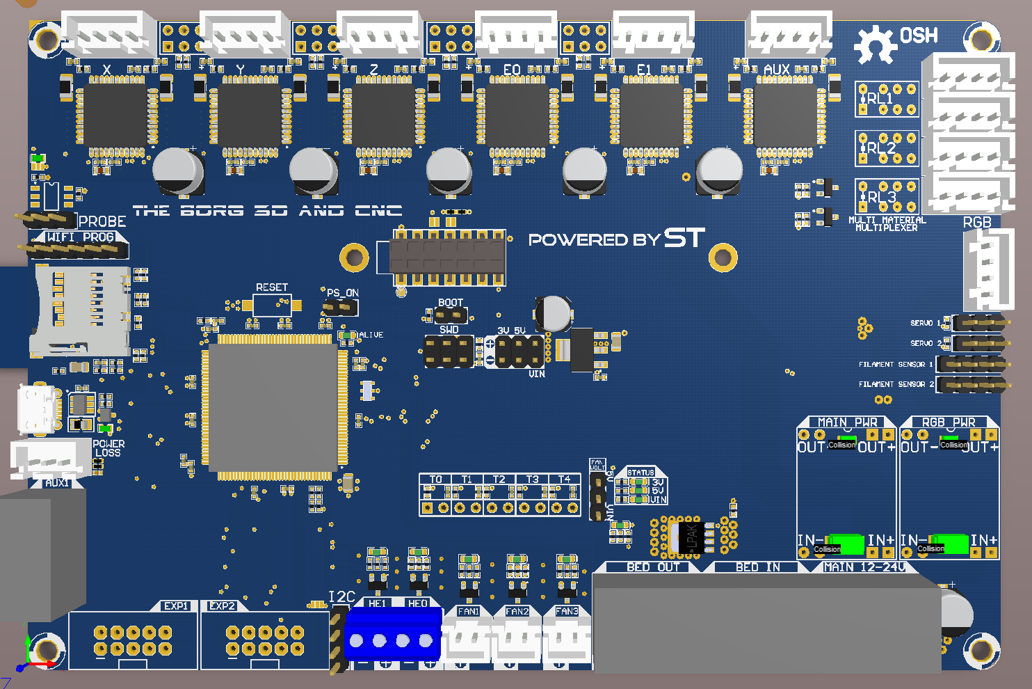
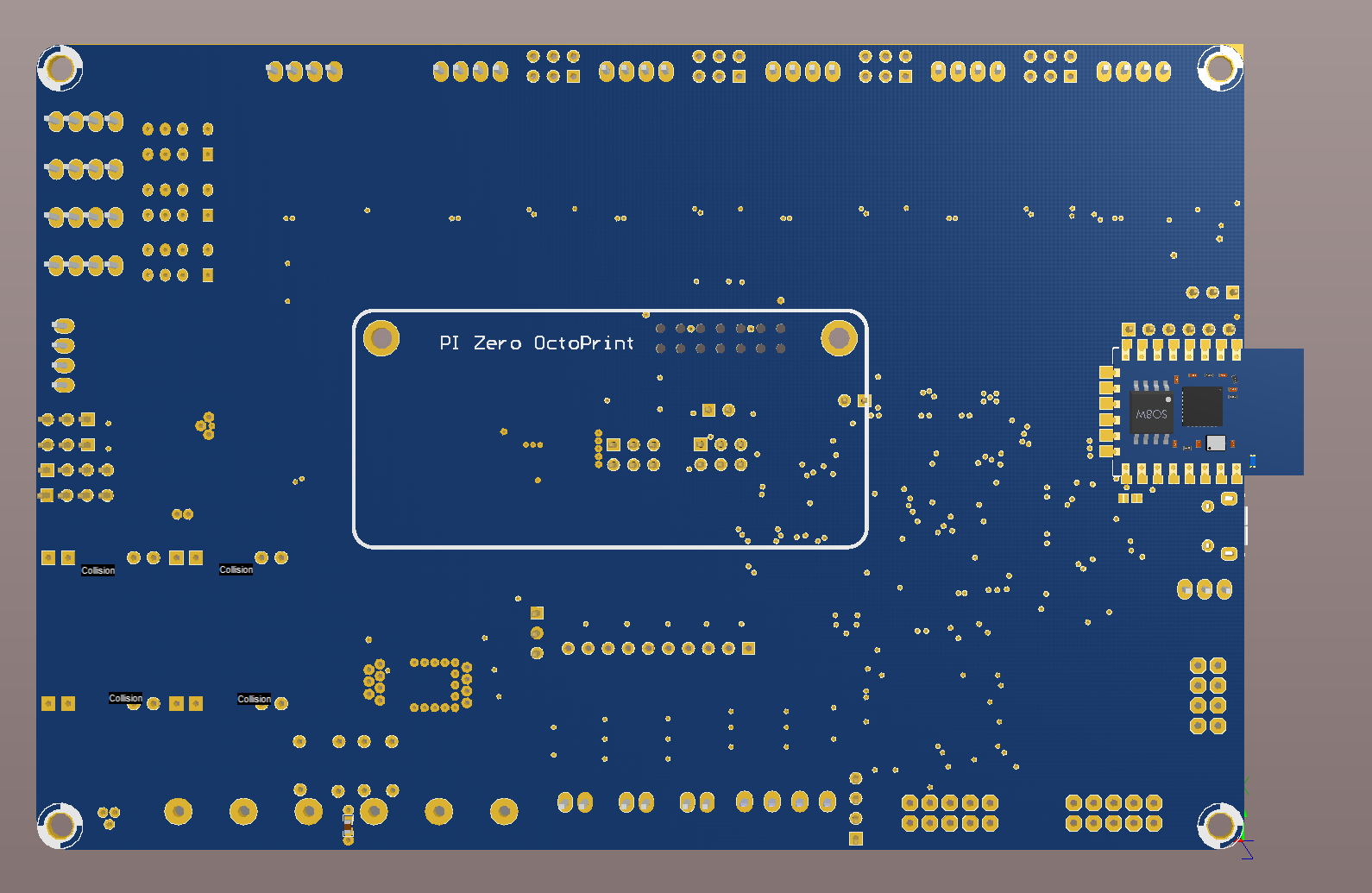
And now a short commercial :)
New board coming along nicely, almost finished, who want's to start adapting ST's F7 HAL to Marlin ? ;)
If too many of you want to, we must have a ticket system, LOL
Some 3D graphics missing or wrong, dont have step models for them yet....
@Roxy-3D I will look into reading encoders as you mentioned before i finish it...
Spawn32
on 2 Nov 2017
@Spawn32 Nice board. I have designed my own about an STM32F103/407VET. Got the first revision a couple of weeks ago and was able to print fine, but messed up some connectors order and have to use cables to switch around signals. Next revision should be arriving in the mail tomorrow and hopefully soldered this weekend and will see how it goes.
I think an F7 is an overkill for a 3d printer, but why not?
I designed 2 versions of my board, with 8 steppers and with 6. First rev was with 8 steppers, second rev is one with 6. The 6 stepper version fits in 100x100mm, so I'll try to work out the issues on that since it's much cheaper to produce, then will move up in size.
Everything works great, other than my mess up with the connectors. I have 4 ADC inputs, 3 large power FETs, 1 low power fet (for fan), and decided to keep the steppers in pololu sockets, but then I miss being able to use SPI steppers :(
 victorpv
on 2 Nov 2017
victorpv
on 2 Nov 2017
Thanks @victorpv , it's just so nice to make your own board, and why not if you can do it :)
Yes, the F7 is a little overkill, but i compered the price on the M4 i was going to use first and it was exactly the same, and who knows, this raw MCU power might come in handy for 256 stepping and we might get Rtos / FreeRtos at some point :)
It's 150x100, the TMC2660 takes a lot of space and i am trying to only use 4 layers, 6 layers doubles the price of the pcb :/
It's almost always that way with the first batch, something get's overlooked :)
Spawn32
on 3 Nov 2017
I don't think it's overkill really. If you want to increase usability closer to industrial standarts you need add a plenty periferials. Motors and sensors for loading filament f.e. like in Stratasys etc...
karabas
on 3 Nov 2017
Looks really great. I had been tinkering with a board design as well. Just some minor remarks:
- Standard blade fuses as protection
- Low pass filter for all PWM
- Noise filter caps for the endstops
- Protection flyback diodes for the drivers (I have killed some of my first tmc2100 - own stupidity). Would be a pity to replace the whole board
 Sineos
on 3 Nov 2017
Sineos
on 3 Nov 2017
@Sineos Thanks for the input 😄
using d-sun "buck" boards, the will take the beating if something happens, easy to replace and only 0.5usd :)
In place ...
adding now..
didn't think about that, i see that the boards using TMC21xx does have som really heavy protection, but then again, the Duet3d that uses TCM2660 dosent have anything ? maybe the 2660' can tolerate more ? but would need a total redesign around my steppers, and also maybe switching to 6 layers, really noe space left :/
Spawn32
on 3 Nov 2017
Going after the data sheets the additional protection is only mentioned for the tmc2100. Seems the newer variants are doing better.
It only mentions some protection on the SRA and SRB pins.
Sineos
on 3 Nov 2017
Related issues
 spanner888
·
4Comments
spanner888
·
4Comments
 Bobsta6
·
3Comments
Bobsta6
·
3Comments
 Anion-anion
·
3Comments
Anion-anion
·
3Comments
 ahsnuet09
·
3Comments
ahsnuet09
·
3Comments
 modem7
·
3Comments
modem7
·
3Comments
Most helpful comment
And now a short commercial :)
New board coming along nicely, almost finished, who want's to start adapting ST's F7 HAL to Marlin ? ;)
If too many of you want to, we must have a ticket system, LOL
Some 3D graphics missing or wrong, dont have step models for them yet....
@Roxy-3D I will look into reading encoders as you mentioned before i finish it...