Marlin: [BR] AUTO_BED_LEVELING_BILINEAR - layer(s) left to right titled
My layer(s) always seem to be tilted on the build plate. With tilt I mean that on the left side the nozzle seems to be too high (1) and the right side too low (2) compared to the middle (0). It doesn't seem to matter how big the printed object is.
In the example shown I printed the first layer of a rectangle 200 x 200 mm and as you can see the left is too high / right too low. The nozzle seems to gradually lower itself while printing from left to right. Top / Bottom doesn't have the issue. I'm using Marlin V1.1.4.

What can I do to better analyze the problem?
 Lord-Quake
All 118 comments
I cannot explain why it is happening, but I can say that the same thing has happened to me using UBL, most recently with 1.1.2. After the initial probing (G29 P1) and filling in the un-probed areas (G29 P3), when I ran G26 to check the leveling, the results were as you described above; poor/no adhesion on the left side, too close on the right side with a pretty linear trend in between (middle of plate was just about perfect). Front to back was pretty consistent, but the front left had almost no adhesion were the back left would at least hold the pattern. While I was trying to figure out the whole UBL process, I must have run G29 P1 10 or more times using anywhere from a 10X10 to 5X5 matrix and the results were the same every time; it didnt seem to matter if the heaters were on or off during probing. I thought then that it was weird that the probe inaccuracies were so consistent from one side to the other time after time. I was able to fairly easily adjust all the points (G29 P4) so that I got good adhesion across the bed, so never really went back to figure it out. As I recall, the bed itself turned out to be pretty flat.
 BillyBob54
on 11 Jul 2017
BillyBob54
on 11 Jul 2017
Oh, by the way - I have a BLTouch probe installed
BillyBob54
on 11 Jul 2017
I had a similar problem. My probe Y offset was out by 2mm.
 benlye
on 11 Jul 2017
benlye
on 11 Jul 2017
Hmmmmm - I'll double check that tonight but thought I looked at that pretty closely when I started.
BillyBob54
on 11 Jul 2017
Would bed levelling debug be of any use here ? I had a similar issue but worse that it gouged by bed, showing it clearly allowed travel below the Z nozzle offset (below min software endstops). This means that either the probe during homing got an erroneous result (which makes no sense since the probe repeatability is dead on within +/-0.08mm worst case (typically +/- 0.03)) or there's some odd bug.
It's a stock Printrbot Simple Metal inductive probe. First time this has ever happened since 2014 through stock PB fork 3-point linear, Marlin 1.1 RC7 LINEAR and MBL without any issues. 2 days of trying to get BILINEAR working on 1.1.3+bugfix1.1 and bad gouge happened. It was in fact identical gcode to that which ran the night before without gouging the bed. Normally that would point to HW but I can't find anything wrong with it. Confirmed all EEPROM settings were set/stored/remain consistent. Prob XYZ offset of course set correctly.
 fiveangle
on 11 Jul 2017
fiveangle
on 11 Jul 2017
Would bed levelling debug be of any use here ? I had a similar issue but worse that it gouged by bed, showing it clearly allowed travel below the Z nozzle offset (below min software endstops).
@fiveangle, were you using endstop interrupts, by chance? There were a few reports of people having endstops trigger but the printer failing to register it when using endstop interrupts, myself included. I don't think it was ever fully investigated. I think you were in the discussion in #6807?
benlye
on 11 Jul 2017
Nope: Printrboard has one axis on non-interrupt capable pin so not using it. I already considered that (if it were tied to that issue you mentioned).
The mystery continues !
fiveangle
on 11 Jul 2017
@Roxy-3D - There couldn't possibly be any issue with the least-squares fit method vs the qr-solve that it replaced in these newer schemes (and now in LINEAR) ? There's a ghost in the machine somewhere it seems there are relatively limited places it can be. So peculiar...
fiveangle
on 11 Jul 2017
I put in code to print the 'solutions' from both the QR_Solve code and the new least squares fit code and compared them. Other than the numbers being negated, they were identical. And you can see in the Pull Request the negation to get the numbers identical. Bi-Linear does not use the Least Squares Fit... So even if that was the cause, it would not explain the Bi-Linear impact.
I cannot explain why it is happening, but I can say that the same thing has happened to me using UBL, most recently with 1.1.2. After the initial probing (G29 P1) and filling in the un-probed areas (G29 P3),
And BillyBob is seeing this with UBL. UBL is where the new Least Squares Fit code was developed. That is the most tested and 'correct' implementation of it.
 Roxy-3D
on 11 Jul 2017
Roxy-3D
on 11 Jul 2017
@Lord-Quake Is it possible to turn the current up on your stepper motor driver chips? And can we turn the max feed rate and acceleration down a little bit (temporarily) in your configuration.h file? I'm wondering if the stepper motors are losing position because they can't move fast enough. It would be good to rule out this possibility.
Roxy-3D
on 11 Jul 2017
Bi-Linear does not use the Least Squares Fit... So even if that was the cause, it would not explain the Bi-Linear impact
I was not aware of that. Thanks for clarifying ! Yes, very peculiar.
fiveangle
on 12 Jul 2017
Bi-Linear is a mesh based leveling system. The term Bi-Linear comes from the way the printer approximates a point. If it is trying to move the nozzle into the middle of a mesh cell, what it does is a Bi-Linear interpolation. First, it interpolates how far the nozzle is moving into the mesh cell along the Y axis. It has the Z-height for all four corners of the mesh cell. So, next it calculates the Z-height of each of the Y lines (where the X location is). It then uses the amount of X the destination is into the mesh cell using those previously calculated Z-Heights along the Y border of the mesh cell.
Hence... It is doing a Bi-linear interpolation. First in one direction. Then 90 degrees to that first calculation.
Roxy-3D
on 12 Jul 2017
So it does no overall plane offset vector calc (like in 3-point or LINEAR, to potentially reduce the overall offsets at each probe point before begining the interpolation), but instead just runs the bilinear on the absolute probe offsets observed. Got it. No wonder it's relatively efficient but still decently effective (if only I could get it to try and not bend space and time by having the nozzle occupy the same space as the bed ;)
fiveangle
on 12 Jul 2017
Does Linear bed leveling fit into your 128KB board now that it is 7.7 KB leaner?
Roxy-3D
on 12 Jul 2017
Surely it does, since BILINEAR does, but LINEAR doesn't really work well my bed as it's only 150mm square (so I always struggle to fit parts onto the space) and the upper right corner of the MIC6 bed is definitely pushing their +/- 0.3xx mm flattest specs so I need levelling that can follow a contour. MBL works, but I just feel wrong having the bed countour travel through the entire print (my OCD bleeding through ;)
fiveangle
on 12 Jul 2017
MBL works, but I just feel wrong having the bed countour travel through the entire print (my OCD bleeding through ;)
Actually... That is almost trivial to change. I have never used MBL. But I used it as the foundation for UBL. I know exactly how it hooks in and what it thinks about things. Seriously.... We can add F-ade to MBL in a couple hours of work. Do you want to give it a try? If so, we should probably start with a fresh fork of bugfix-1.1.x just so we can merge it when we think it is 'right'.
Roxy-3D
on 12 Jul 2017
@Roxy-3D My board does not have the ability to change stepper motor current with the only exception of the extruder stepper.
Lord-Quake
on 12 Jul 2017
We can add F-ade to MBL in a couple hours of work. Do you want to give it a try? If so, we should probably start with a fresh fork of bugfix-1.1.x just so we can merge it when we think it is 'right'.
I'm game ! https://github.com/fiveangle/Marlin/tree/mbl_zfade :)
fiveangle
on 12 Jul 2017
My board does not have the ability to change stepper motor current with the only exception of the extruder stepper.
OK. But you can still back off the max feedrate numbers and the acceleration number by 25%.
Roxy-3D
on 12 Jul 2017
I'm game ! https://github.com/fiveangle/Marlin/tree/mbl_zfade :)
I was getting set up to help you do this... But it looks like Fade is already implemented for Mesh Bed Leveling:
#if ENABLED(MESH_BED_LEVELING) || ENABLED(AUTO_BED_LEVELING_BILINEAR) || ENABLED(AUTO_BED_LEVELING_UBL)
  // Gradually reduce leveling correction until a set height is reached,
  // at which point movement will be level to the machine's XY plane.
  // The height can be set with M420 Z<height>
  #define ENABLE_LEVELING_FADE_HEIGHT
#endif
@Roxy-3D are you referring to these?:
#define DEFAULT_MAX_FEEDRATE          { 400, 400, 8, 50 }
#define DEFAULT_MAX_ACCELERATION      { 2000, 2000, 100, 10000 }
The above is what I'm using. What do you want me to use for the test?
Lord-Quake
on 12 Jul 2017
Yes. Cut those to 75% of their current values and lets see if it still shifts. If it does... we probably have a firmware issue.
Roxy-3D
on 12 Jul 2017
I've done the test with the following settings:
#define DEFAULT_MAX_FEEDRATE          { 300, 300, 6, 36 }
#define DEFAULT_MAX_ACCELERATION      { 1500, 1500, 75, 7500 }
The results are the same. Using a mechanical caliper I measure 0.35mm left and 0.25mm right for the first layer so I'm seeing a 0.1mm difference.
Side note:
// #define ENABLE_LEVELING_FADE_HEIGHT
is deactivated.
Lord-Quake
on 12 Jul 2017
Just for curiosity, what is the status of the
define MIN_SOFTWARE_ENDSTOPS
?
I experienced the same and after redoing the bed leveling, (it was really bad) and commenting out MIN_SOFTWARE_ENSTOPS, it seems to be working OK.
 jeno007
on 12 Jul 2017
jeno007
on 12 Jul 2017
@jeno007 Status is
//#define MIN_SOFTWARE_ENDSTOPS
Lord-Quake
on 13 Jul 2017
Is there anything further I can do to debug the situation?
Lord-Quake
on 14 Jul 2017
The above diagram got me thinking about an issue that I had as I was initially setting up UBL that may (or may not) have something to do with the original post in this thread:
I do not recall where the below quote came from; As I was researching setup/use of UBL, I compiled a set of notes combining the several sources of information for ready reference and I came across the following (I do not recall where the below quote came”:
“One concept that is important to remember and that will make using the Phase 4 command easy to use is this: You are editing the Mesh Points. If you have too little clearance and not much plastic was extruded in an area, you want to LOWER the Mesh Point at the location. If you did not get good adhesion, you want to RAISE the Mesh Point at that location.”
As I interpret the above, during the P4 correction routine if the nozzle was too close to the build plate at a given mesh point, and the mesh offset was say 0.1, to correct you would LOWER the mesh to .05 (just examples). If there was not enough adhesion, you would RAISE the mesh to 0.15. This in practice only made things worse. After several failed attempts, I realized that if I did the opposite, I could dial the mesh in in just a couple of passes. So, 2 questions:
- Is the above quoted instruction accurate and is my interpretation of it correct?
- If the instruction and interpretation is correct, is it possible somehow the mesh correction is being applied “backwards”. Everything else concerning the Z axis operates correctly, baby stepping, Z offset, etc). If the bed had a general left-to-right tilt, an inverse application of mesh correction would result in to tight clearance on one side, to high on the other. If the tilt was too great, bed collision would result. If fairly flat, you might not notice it at all. To be honest, I am not sure what the general geometry of my bed was before I started; final mesh did indicate that it was fairly level but there might have been a general tilt.
I have 1.1.4 all set up and ready to load, but just have not had time to play with it (maybe this weekend)
I would just like to say that the work everyone has put into UBL (and all the other methods and Marlin capabilities) is incredible. Thanks for all the great work and support!
BillyBob54
on 19 Jul 2017
Self answered question one above:
@Roxy-3D; in #6399 , you write
On April 23rd you write:
“But... The way the system works is you can now move the nozzle over an area of the bed that is not 'perfect' and issue a G29 P4 R. You can dial up or down each mesh point. As a rule of thumb... If the line is too squished down and too thin... Bring the mesh point up. Don't go crazy... but depending on what you see, bring it up .1 or .2 mm. If the line is just barely adhering to the bed, bring the mesh point down .1mm. If the line is not adhearing at all, bring it down .25mm.”
On the 24th;
“After you do a G26 command, the mesh validation pattern will be on the bed. Different areas may be less than 'perfect'. Move the nozzle to the center of the area that is flawed. Do a G29 P4 R command. The nozzle will go to the closest mesh point that has not been edited yet. You can turn the encoder wheel to adjust what should happen at that mesh point. If you have bad adheasion at the mesh point, bring the nozzle down a little bit. If the filament is squished too thin at the mesh point, bring it up 'the right' amount”
The above 2 comments almost seem to contradict each other, but on the 25th, it appears that you clarify the above two comments:
“The mesh numbers say what to do to the nozzle to make it track the bed. So if the nozzle is too close to the bed... What ever the number is currently, make it bigger. Make it more positive. Make it less negative.
If the nozzle is too far from the bed... bring the mesh point number down. make the mesh point number smaller. make it more negative.
If you have any adhesion at all... don't move the number by more than .15 mm .15mm will cause a visible difference in how the lines at that point appear. You want the mesh lines to be flat on the top (because they are being squished into the bed) and a little wider than the nozzle's extrusion hole.”
My question #1 above is answered – it is not correct (at least my interpretation). That’s good because it works the way that I actually corrected my mesh! The second question remains.
BillyBob54
on 19 Jul 2017
Yes... It is easy to make a mistake with this stuff. I said the wrong thing. The mesh point value is added to the Z-Height so the nozzle will track the bed. If you have a dip in your bed, the mesh point value will be negative, and adding that value to the Z-Height will pull the nozzle down at that location so the nozzle can track the bed.
If you can print a G26 pattern... Pick a random mesh point and add 1 or 2 mm to it. Make it positive number. And when you print the validation pattern, you will see the nozzle lift up in that area and not print those lines.
Roxy-3D
on 19 Jul 2017
@Roxy-3D After reading your last post I'm not sure anymore if my specific problem is being understood.
In my case the auto bed leveling is working when you have different heights from one point to the other.
I tested that by placing a metal ruler in the middle of the bed. While printing the height will change accordingly.
The problem "we" are seeing is that within the mesh the movement in height is not constant.
As mentioned in my first post it seems that the layer on the left is being printed higher compared to the right.
What can I do to provide more debugging evidence?
Lord-Quake
on 19 Jul 2017
@roxy-3D ; no problem - it actually all makes sense once you have the correct perspective and all the 3 of the comments above are really equivalent. Thanks again for all the effort.
@cisforcer - not to worry on the language issue; I speak English natively and I have a hard time understanding this stuff!! If I understand correctly, you are asking why, if G29 P1 generates the correction to account for bed tilt/imperfections, why does any correction have to be applied. G29 P1 generates the mesh that the print head must follow to remain an equal distance from the bed. The results of P1 can be seen by using the G26 routine- it will print a pattern on the bed one layer thick. This mesh will generally not be perfect and must be corrected (mostly due to probe inaccuracies or humps/bumps between probing points). This is done with the G29 P4 routine. The nozzle will move to the closest mesh point, if adhesion of the G26 pattern is too tight or to loose, then correct as per the above post discussions. There is a lot more to this process than I just laid out- Roxy may be able to point you to better instructions.
BillyBob54
on 19 Jul 2017
Same here with UBL, Bilinear and Linear leveling...
 BastR
on 21 Jul 2017
BastR
on 21 Jul 2017
The problem "we" are seeing is that within the mesh the movement in height is not constant. As mentioned in my first post it seems that the layer on the left is being printed higher compared to the right. What can I do to provide more debugging evidence?
Is it possible to capture the problem on video? And then you can tell us what to watch for and we can see the issue.
if G29 P1 generates the correction to account for bed tilt/imperfections, why does any correction have to be applied. G29 P1 generates the mesh that the print head must follow to remain an equal distance from the bed. The results of P1 can be seen by using the G26 routine- it will print a pattern on the bed one layer thick. This mesh will generally not be perfect and must be corrected (mostly due to probe inaccuracies or humps/bumps between probing points). This is done with the G29 P4 routine.
If your probe has very good repeatability, it may be the G26 to check and do a final edit of the mesh is not necessary. On my gMax printer there is a BL-Touch probe. I switched to one of the most recent versions of the probe and magically... I no longer need to do a G26 to perform a final edit. The probing is that good. But even so... The G26 only takes 5 minutes to do. You may as well confirm the mesh numbers you are going to lock in and use are perfect.
Roxy-3D
on 21 Jul 2017
i have a Plastic thinsection for cold printing,its very good first printing 。may be the plastic make the 12mm pnp ccuracy error?
That is the purpose of the G29 J command. If you have your print bed's mesh accurately defined, but it doesn't always hold position... You can tilt that mesh to reflect the current situation. The easiest way to envision a need for this is if you remove the glass to put it in the freezer so the parts release from it. And when you put it back on the heated bed, you some times get a little piece of plastic under a corner of the glass. The G29 J will tilt the mesh to compensate for that.
Roxy-3D
on 21 Jul 2017
@cisforcer; see below link for more detail on the process
http://marlinfw.org/docs/features/unified_bed_leveling.html
Before going there, you may want to go your Marlin folder and open up G26_Mesh_Validation_Tool.cpp. The list of avaialbe commands for G26 is listed there. Also open ubl_G29.cpp ; options fopr the G29 command are provided there as well.
Basicall, after you perform a P1, then G26 to print the test pattern, G29 P4 R will visit all the targets that were printed by G26. If there is not enough adhesion, make the cooresponding mesh point (as displayed on the LCD) smaller (or more negative), if to close, make the number bigger (or less negative) by rotating the LCD knob- Press the knob one time to move to the next point. See my conversation with Roxy above.
All that said, we have hijacked this thread- the original question concerned a general left-right tilt aafter the initial leveling routine. My appolgies to the OP
BillyBob54
on 21 Jul 2017
@BillyBob54 No problem what so ever. Learning a lot!
Lord-Quake
on 21 Jul 2017
Here another test that shows ABL is working as it should. I tilted the bed by several degrees and then did a 5x5 mesh calibration.
I then did the same print as in my first post with the same results. The left side is printing too high and the right side too low (x-axis). The layers in y-axis are evenly printed on the bed, no tilt changes.
Lord-Quake
on 21 Jul 2017
Here another test that shows ABL is working as it should. I tilted the bed by several degrees and then did a 5x5 mesh calibration.
And you don't need to save the new mesh... But if you do a G29 P4 R with the nozzle in the lower right of that picture.... And lower ever point in that corner by .1 mm And.... redo that same print.... you will see the filament get smooshed together better.
Or... Instead of doing that... Do a G29 J4 on the empty glass... And the mesh should auto correct.
Roxy-3D
on 21 Jul 2017
I'm not using glass on my aluminum heat bed but only a very thin layer of Kapton film.
I've never used G29 J4. Should I still use it with Kapton? What does the code do?
Lord-Quake
on 21 Jul 2017
It would have probed the bed and tilted the mesh the 'correct' amount to make your pictures up above be 'normal'.
Roxy-3D
on 21 Jul 2017
If you want to debug ABL_BILINEAR at various points around the bed, you can enable DEBUG_LEVELING, then send M111 S32 to enable extra logging, and then G29 Q can be used report the status of bed leveling, including the amount of Z adjustment (unfaded) at the current XY position.
Move around to different points across the bed and do G29 Q to see if the Z adjustment is sensible and matches the grid points that were originally measured and saved by G29.
The left side is printing too high and the right side too low (x-axis).
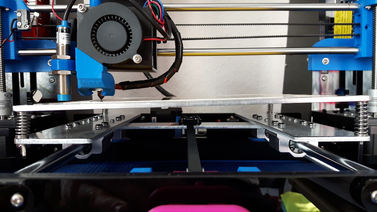
You'd think that if there was some proportion error, it would be seen in both the X and Y —more in one corner than in the opposite corner— and not just on the X. To rule out a mechanical fluke, make sure the carriage isn't getting pulled upwards by the filament, tube, or cables as it moves along the axis.
Another thing to test is whether the probe is triggering at different heights at different points on the bed. The BLTouch is a pretty good probe, but it might be affected by subtle magnetic fields that could change its measurement height. You could try using the PROBE_MANUALLY option and compare the resulting mesh to the one produced by the BLTouch auto probe, to see if the result is any better.
 thinkyhead
on 22 Jul 2017
thinkyhead
on 22 Jul 2017
After doing my tilt heat bed test I mounted the heat bed back to it's normal position doing a manual 4 point adjustment with extruder nozzle. After that I heated the bed to 55°C and did a 5x5 auto level calibration which I saved to eeprom (M500) for later prints. Here is another test with the same results.

I can confirm:
- Carriage isn't getting pulled upwards by the filament.
- Cables are not interfering with extruder movement.
- X carriage idlers have free movement on the guide rails.
Lord-Quake
on 22 Jul 2017
In my opinion doing a manual probe leveling will not help in solving the problem. The print will only be as good as how well the user manually sets up the build plate. Never the less I did it anyway.
After doing the manual setup I had to recalibrate the 5x5 matrix because the build plate had now changed again.
Both results are shown in the picture.

Lord-Quake
on 23 Jul 2017
The question about the manual probe or auto probe is : Why one works and another not, basically , a mesh is created in manual probe and the printer obey the distances but not in auto mode. I'm not a programmer , and my opinion is very superficial , but looks here that mesh created in auto mode is wrong stored or ignored in print process
Is this possible ?
 agambini
on 23 Jul 2017
agambini
on 23 Jul 2017
Sorry for my english
agambini
on 23 Jul 2017
how to change values by g29 j command?
Don't use the G29 J right now... We want the mesh accurate before we add any complexity. And once the mesh is accurate, it is very likely you want need the G29 J because you are printing straight on the bed.
i do nothing with my printer but after g29 p1 and g26 its printing nicer then days before with using UBL there still has a little different between left and right corner
So... Move the nozzle to that corner that is not perfect. Give it a G29 P4 R command. I'm making some assumptions about your machine. But lower the corner by .1 mm and lower 3 nearest points by .05mm. Do another G26 and you should see that area have much better adhesion. And using that information... Go tweak other areas of the mesh that are not absolutely perfect.
It should only take 2 or 3 iterations to get the mesh perfect. (You can edit multiple problem areas on each G26 pattern before repeating the process.)
Roxy-3D
on 24 Jul 2017
I understand that the mesh can be corrected manually, but why the mesh is not correct after the automatic measurement? In case we have a correction problem, by solving it via the mesh we just hide the problem. Many of us see similar problems and manual correction is not always feasible. I have a simple removable bed to make it easy to remove the parts, manually correcting after every piece is not practical.
jeno007
on 24 Jul 2017
The question about the manual probe or auto probe is : Why one works and another not, basically , a mesh is created in manual probe and the printer obey the distances but not in auto mode. I'm not a programmer , and my opinion is very superficial , but looks here that mesh created in auto mode is wrong stored or ignored in print process
Is this possible ?
agambini
on 24 Jul 2017
I understand that the mesh can be corrected manually, but why the mesh is not correct after the automatic measurement?
The probes are not always accurate. And the machine can distort measurements. And adding to this, the probe is offset from the nozzle. Things get complicated very quickly.
Roxy-3D
on 25 Jul 2017
Yes, automatic bed leveling requires some precision.
jeno007
on 25 Jul 2017
Roxy-3D, can you tell us some about how datas are readed , stored and used by the printer when do auto level ?
agambini
on 25 Jul 2017
Roxy-3D, I started to review and understand the code (focusing on bilinear only).
In Marlin_main.cpp in line 5043 there is the following:
   // Unapply the offset because it is going to be immediately applied
    // and cause compensation movement in Z
    current_position[Z_AXIS] -= bilinear_z_offset(current_position);
It's an unconditional change which seems to me does not check the M420 state and the leveling fade Z height.
jeno007
on 25 Jul 2017
Roxy-3D, can you tell us some about how datas are readed , stored and used by the printer when do auto level ?
i would give up with UBL because its need g29 p4 r (manual checking by human )
i need auto bed no humanity
Guys... The auto probing gets you pretty close to a perfect mesh. The G29 P4 R lets you edit (and save) a more perfected mesh. I don't even have a G29 in my Slicer Start Up GCode. UBL is alive and working (with a perfect mesh) every time the printer powers up. Its not like UBL forces you to have human interaction. Its almost the opposite. You set it up once to have perfect adhesion across 100% of your bed and you get that 100% of the time you start a print.
Roxy-3D
on 26 Jul 2017
@cisforce, can you heat the bed before probe ?
I will try the Roxy-3D suggest, maybe the diffs of the probe measures still on 0.0XX mm , I'm sure that the auto level will more and more better with time
agambini
on 26 Jul 2017
I made an excessive testing on ABL (not UBL!!) bilinear.
I enabled
define DEBUG_LEVELING_FEATURE
and added a lot of debugging code to catch every step of the process as it progress.
I also added
define M114_DETAILS
which enabled M114 D, which provides a lot of useful information, not just the position, but the leveled and unleveled position and even the stepper count and the position based on the stepper count.
I calculated manually the bilinear interpolation and the necessary offsets at many given points and compared them to what was applied by the firmware. Everything was OK down to the um level.
The only findings I made is that ABL G29 enables the bed leveling at the end of the process (NO!! M420 required), but during the enabling it does not count with the LEVELING_FADE_HEIGHT, thus miscalculate the position.
So what can cause the problem I also have seen on my printer? (I'm using original BLTouch).
In bilinear ABL (and UBL mesh as well), we do a lot of measurement. I'm using 9x9 matrix which means 81 measurement. By statistics, 4.2% of them are between 2 to 3 sigma (sigma=standard deviation) away from the real value.
On the BLTouch homepage they claim 5 um standard deviation, with a comment that it was a precision machine and on a home machine the standard deviation can go up to 50 um.
It means that in 4.2% of the 81 measurement in my case (which is at least 3 measurement) the measurement error could be +/- 0.15 mm, which definitely effects the 1st layer.
It also explain why manual probing helps, by correcting the bad values. Manual probing can be definitely better than +/- 0.15 mm.
So what is the solution?
Reducing the number of the measurement is not. :smile:
We have to increase the precision of the sensors (by calculating with the 5 um standard deviation the error would be only +/- 0.015 mm, which is much more acceptable).
The sensor precision is a sum of a lot of factor, the sensor itself, the detection delay etc.
The detection delay could be improved by the interrupt based end-stop feature, what I had to disable due to the rare cases when it was not working and the sensor and the head crashed to the bed. It should be fixed.
Also the speed of approach could improve it. It seems that the default slow speed for the 2nd approach is 2mm/s. Maybe reducing it to 1 mm/s helps. (I'll check it).
Even we can create a special motion mode when the end-stop status is checked after every microstep, but that's too far.
At the end we can use a better sensor. BLTouch claims to be a good one, but the Prusa's PINDA like probe (a 12 mm diameter, 2 mm distance inductive sensor) is definitely better.
jeno007
on 27 Jul 2017
We have to increase the precision of the sensors (by calculating with the 5 um standard deviation the error would be only +/- 0.015 mm, which is much more acceptable).
One thing that has been done is the option to not be switching high current loads on the wires near the BL-Touch while actually probing a point. Depending upon how your printer is setup, this can make a big difference.
So what is the solution? Reducing the number of the measurement is not. :smile:
One answer is you use the probing to get you close to the final answer, but you don't depend on it being correct. UBL allows you to automatically probe the mesh and thing fill in the unprobed mesh points. This is used as a starting point to further refine the mesh with G26 and G29 P4 R.
Roxy-3D
on 27 Jul 2017
Is anyone of the programmers looking into the "tilt" issue?
Lord-Quake
on 27 Jul 2017
@Lord-Quake What method do you use (ABL or UBL), and what kind of probe?
I'm not a contributor to Marlin, but have the same problem as yours so I try to investigate.
As you can see above as much I can see the "correction" code is OK, so I assume the problem is with the measurement. It can be the probe, but also can be the height measurement code. I'll check this one as well, but I'd like to know if it can be probe related.
I'm doing ABL Bilinear with BLTouch.
jeno007
on 27 Jul 2017
I'm using a LJ12A3-4-Z / BX NPN NO 4mm Inductive Sensor which is one of the more precise versions.
Marlin is configured with ABL - Bilinear.
Lord-Quake
on 27 Jul 2017
And in this case what is your bed material? Alu?
jeno007
on 27 Jul 2017
ALU with a very thin Kapton film layer.
Lord-Quake
on 27 Jul 2017
Yes, your sensor should be OK.
Based on this and that the same problem appears booth in ABL and UBL, my bet is that the problem could be with the height measurement code. I'll try to measure that, ie. measure manually with the business card method and compare the results.
jeno007
on 27 Jul 2017
You mean you tried both ABL Bilinear and UBL mesh?
In case ABL Bilinear, what is your grid size?
Also @Lord-Quake what is your grid size?
On 2017. júl. 28., at 3:09, cisforcer notifications@github.com wrote:
when auto bed leveling bilinear , the point 1、2 too close to the edge left , Holzer testing less metal
so low nozeel
https://user-images.githubusercontent.com/30031297/28698128-c5ee3ea6-7373-11e7-9d8f-c6c3fb39bca7.jpg
—
You are receiving this because you were mentioned.
Reply to this email directly, view it on GitHub https://github.com/MarlinFirmware/Marlin/issues/7278#issuecomment-318528574, or mute the thread https://github.com/notifications/unsubscribe-auth/ACFZVy_6ErcTgdjGkclGbYCmedQy6x1qks5sSTS7gaJpZM4OUkyd.
jeno007
on 28 Jul 2017
200x200mm
Lord-Quake
on 28 Jul 2017
I ment how many grid points?
How many points are measured?
Sent from my mobile
- júl. 28. dátummal, 7:47 időpontban Leo notifications@github.com írta:
200x200mm
—
You are receiving this because you were mentioned.
Reply to this email directly, view it on GitHub, or mute the thread.
jeno007
on 28 Jul 2017
I'm using either 3x3 or 5x5.
Lord-Quake
on 28 Jul 2017
@Roxy-3D , Can you help me , with step-by-step UBL fining tuning, I'm confused because I don't know how to down the noozle to do measures,
I do G29 P3 but noozle not respect the Z offset
agambini
on 29 Jul 2017
If you can print without any bed leveling... You just need to do a G29 P1 and a G29 A to activate. If you can print a small calibration cube in the center of the bed with no bed leveling firmware active.... With UBL a G29 P1 and a G29 A will let you print across most of your print envelope.
Roxy-3D
on 29 Jul 2017
Don't want to add noise to the conversation here but just wanted to report that I've had similar issues with AUTO_BED_LEVELING_BILINEAR on my Kossel running 1.1.4 (also tried bugfix branch) using a BLTouch probe. The G29 V4 grid looks okay but the nozzle does not seem to be compensating properly. On the right side of Y axis, the nozzle is too low and left side it's too high.
 azeem
on 9 Aug 2017
azeem
on 9 Aug 2017
@azeem Thanks for the confirmation. It's been a month and I still can't tell if the issue is being looked into :-/
Lord-Quake
on 10 Aug 2017
Is there a pattern emerging where only those using BLtouch with Bilinear ABL are seeing this issue ?
Similar issue here #7452
fiveangle
on 12 Aug 2017
I'm not sure what youv'e done here already, but what I posted in #7452 :
a few things:
- You need to enable bed levelling every time you want to use it with
M420 S1: is that being done ?- Assuming you're doing that, what is output of
M420 Vto see the stored leveling data ?- Assuming all that looks good, enable
Z_MIN_PROBE_REPEATABILITY_TEST, compile, runM48, and show us the outputDo you have that picture looking straight-on from the front viewing across the bed edge with the carriage close to it so you can see the relation of the cariage with the frame/bed ?
and I didn't see any detail above from Scott's suggestion:
If you want to debug ABL_BILINEAR at various points around the bed, you can enable DEBUG_LEVELING, then send M111 S32 to enable extra logging, and then G29 Q can be used report the status of bed leveling, including the amount of Z adjustment (unfaded) at the current XY position.
Move around to different points across the bed and do G29 Q to see if the Z adjustment is sensible and matches the grid points that were originally measured and saved by G29.
That seems like the best since you can view/save terminal output while moving around the bed (without printing and potentially gouging things)
fiveangle
on 12 Aug 2017
@fiveangle I don't know if your comments where directed towards me.
I did the following tests:
Left:
20:06:04.003 : M48 Z-Probe Repeatability Test
20:06:50.238 : Finished!
20:06:50.238 : Mean: -0.126750 Min: -0.135 Max: -0.120 Range: 0.015
20:06:50.238 : Standard Deviation: 0.004617
Center:
19:54:57.142 : M48 Z-Probe Repeatability Test
19:55:42.626 : Finished!
19:55:42.626 : Mean: -0.136500 Min: -0.145 Max: -0.120 Range: 0.025
19:55:42.626 : Standard Deviation: 0.007263
Right:
20:07:47.253 : M48 Z-Probe Repeatability Test
20:08:36.425 : Finished!
20:08:36.425 : Mean: -0.398750 Min: -0.413 Max: -0.378 Range: 0.035
20:08:36.425 : Standard Deviation: 0.010969
Debug:
G29
20:15:32.567 : Bilinear Leveling Grid:
20:15:32.567 : 0      1      2
20:15:32.567 : 0 +0.032 +0.005 -0.210
20:15:32.567 : 1 -0.120 -0.143 -0.368
20:15:32.567 : 2 -0.055 -0.045 -0.253
20:15:32.567 : G29 uncorrected Z:10.98
20:15:32.583 : corrected Z:11.23
G29 Q will do nothing when I enter the code.
Lord-Quake
on 12 Aug 2017
I did the following tests:
Your probe seems to be reasonably reliable. If you do several G29 passes and compare the resulting grids, do they come out more or less the same?
Is anyone of the programmers looking into the "tilt" issue?
It's been a month and I still can't tell if the issue is being looked into :-/
I asked for some debugging output from those experiencing the issue, but it seems to have been missed. With lots of log output we can better understand what's going on. Data, data, data. Without it, we will just be hunting in the dark.
So, assuming AUTO_BED_LEVELING_BILINEAR with a real probe, here's the boilerplate…
- Enable
DEBUG_LEVELING_FEATUREand flash. - After
G28useM111 S247to enable full logging. _Importante._ - Do your usual
G29and collect the log output. - Afterward, check the result with a test print. If the problem exists…
- Move the nozzle around the bed, using
G29 Qto see what the mesh offset is at various points
- Move the nozzle around the bed, using
Collect all that log output in a file, zip it up, and drop it onto a followup reply here.
thinkyhead
on 28 Aug 2017
@thinkyhead As soon as I return from my vacation I will try to gather the information as described above.
Lord-Quake
on 29 Aug 2017
Pretty busy this week. I am using UBL but having the same issues; after
probing one side of pattern is good, the other side too high. Will try to
get to it this weekend.
On Tue, Aug 29, 2017 at 3:20 AM Leo notifications@github.com wrote:
@thinkyhead https://github.com/thinkyhead As soon as I return from my
vacation I will try to gather the information as described above.—
You are receiving this because you were mentioned.
Reply to this email directly, view it on GitHub
https://github.com/MarlinFirmware/Marlin/issues/7278#issuecomment-325577257,
or mute the thread
https://github.com/notifications/unsubscribe-auth/ARvmpK5QFzGpjwFoMPKTgEuBUBqs-qEjks5sc7vDgaJpZM4OUkyd
.
BillyBob54
on 29 Aug 2017
OK - got around to doing the above debugging yesterday (UBL- 1.1.5) but when I printed the test pattern (G26), it was dead on (well, at least within the accuracy of the probe). I had done some cable maintenance to ensure that the wire bundle to the print head wasn't pulling on the print head as it moved to the left side of the bed (where the problem was) and had also move to 1.1.5 since this thread started. We dropped power momentarily before I had a chance to copy the log. Will run again tonight and see what happens. Maybe it was a mechanical problem, didn’t see anything in 1.1.5 that would have had an influence - I always thought it was odd that only a few folks were having the problem..
BillyBob54
on 5 Sep 2017
Re-ran everything last night-files attached. Although results after first probing was better than before, the resulting mesh was still a little high on the left side of the bed. Overall the bed is pretty flat. The adjustments required could certainly be attributed to "probe error" but things are consistently (slightly) high on the left side of the bed. Earlier results with 1.1.4 were considerably high on the left - no adhesion at all.
Couple of notes:
I highlighted the Topo maps for easy finding
It only took 2 iterations of G26 to dial everything in
Using 5X5 grid- seems to work fine on a 200X200 bed
BillyBob54
on 6 Sep 2017
Any news about this issue ?
 guiseco
on 14 Sep 2017
guiseco
on 14 Sep 2017
@BillyBob54 Those various G29 T's are fairly consistent. If the G26 Test Pattern is coming out looking good... It means the mesh points are accurately describing the surface of the bed.
I can tell you this: It is very common to have one edge of the glass that is warped. I have posted topographical maps in response to other people saying there is a funny cliff on one side of their bed. I don't know what causes it. But it is very typical to have one edge that deviates from the rest of the surface.
Just for kicks... Can you rotate your glass 90 degrees. My guess is the anomaly will follow where that edge is positioned.
Roxy-3D
on 14 Sep 2017
Hy @Roxy-3D.
I know people using a thin sticker on the bed and the same problem occurs.
guiseco
on 14 Sep 2017
This sticker ->
guiseco
on 14 Sep 2017
I don't have any personal experience with that. But I can say, if a piece of glass can have a warped edge you can not see when you look across it... For sure other things can have warped edges too. There are a lot of pictures of people's bed topology if you search for things like G29 T 1 (1 produces a .CSV format that can be cut and pasted into Excel to do a 3D Plot.)
Most of those pictures have at least one of the edges warped.
Roxy-3D
on 14 Sep 2017
Let us recap.......
The OP stated that after AUTO_BED_LEVELING_BILINEAR, layers on the left side of the bed was too high (i paraphrase greatly). I also reported that I experienced the same thing following UBL. After running G29 P1, G26 would print OK on the right side of the bed, but very high on left side of bed (UBL active). Initially the problem was so great that there was no adhesion on the left at all. Based on the OP's pictures-his results with Bi-linear was better than mine with UBL prior to correction. I could very rapidly correct with a few iterations of G29 P4 / G26. Still, it seemed odd that following both bed leveling routines, the mesh needed to be lowered consistently on the left side of the bed. SInce then, the original post wondered off in several different directions and thankfully, its come back home recenty! In the interim, I addressed some wiring issues that may have been a factor in the left side issue and i also updated to 1.1.5. Now when I run G29, the subsequent G26 shows that UBL is doing its job (pattern prints fairly well across the bed). Given how my system is working currently, not sure that I will be of any use in troubleshooting the OP problem. All that said;
- I am aware of the "edge affect" described above. I personally have found that if I "heat soak" my bed before G29, the affect is lessened. But even if the bed does "roll off", G29 or Bilinear should correct for the phenomenon. Can’t rotate my bed as there is a notch in the back of the glass to avoid the heater connections.
- I am beginning to think that my issue may have been caused by the extruder wiring pulling up on the head as it moved to the right side of the bed (wiring issue I mentioned above).
- Given my current results with G29 UBL, I think that I will "stand down" from this post for now. My above posted files show that UBL is functioning as designed but the OP still seems to be having the same problem.
I have said it before, and I’ll say it again-those of you who are developing this software and all its functionality ROCK!! Thanks.
BillyBob54
on 14 Sep 2017
Wiring issue ???? I also updated to 1.1.5 and my problem yet still there. My M48 return a value below 0.00xxxx, so my sensor is ok but my layer always seem to be tilted on the build plate. Left side the nozzle seems to be too high and the right side too low.
guiseco
on 21 Sep 2017
Wiring issue as the "mechanical wiring" issue. My wiring harness to the head comes from the right side; as the head moves to the left side of the bed, I think the wire was binding a little causing the head to be lifted slightly. That is only a guess, I have re-routed and the problem seems to have gone away. Only other thing I did was load 1.1.5. Can't prove the wire was the problem, would have thought that the leveling routine would have compensated but maybe not. What you describe is the same problem this thread is discussing
BillyBob54
on 21 Sep 2017
Yes. I have exactly the same problem ! :(
guiseco
on 21 Sep 2017
Really fat fingered the last comment :-O; fixed the typos; that’s what I get for trying to type and walk at the same time- good thing I wasn't chewing gum as well!!!!
BillyBob54
on 21 Sep 2017
Rotating the bed surface is definitely a good step in troubleshooting.
So, the current status is: Some users still experience poor adhesion in the left 1/3 of the bed, which manifests in both ABL Bilinear and in UBL. The mesh can be corrected using G26 or M421, and then the bed leveling works properly. In at least one case, cables or filament pulling up on the carriage may have been a factor leading to poor adhesion.
We know with reasonable confidence that the probing code and the mesh code for both ABL and UBL are robust, and are not biased in any sense that would lead to alteration of the probe readings. So it comes down to an issue where either the probe is reading higher on the left side of some beds, or the carriage is tending to lift on the left side during printing.
Spurious issues like this are the reason that UBL —and G26 in particular— were created. My recommendation is to use UBL and follow the full G26 procedure so you know you have a perfect mesh. There's nothing we can do on the firmware side about bad or biased probe readings except offer the ability to make corrections.
Going forward, developers plan to focus attention on setup and calibration procedures, so there will always be an option to do a test grid (or zig-zag) to make sure the leveling is good, regardless of the leveling procedure used. In the meantime the G26 procedure is just what the doctor ordered.
thinkyhead
on 26 Sep 2017
LINEAR works perfect for me. Bilinear not !
guiseco
on 26 Sep 2017
Update:
Coming back from vacation I first updated to 1.1.5.
Because guiseco mentioned that linear works for him I decided to do my own test. No change in the result; Bilinear and Linear both show a tilted print.
Since the developers are sure that the code is sound I can only think of one last culprit. Likely cause could be that the aluminum bed has different metal densities (in my case more on the left side compared to the right side) which could make for very slightly different measured heights.
The only option I have now is to do a manual correction for each probing point (if that's even possible with my printer board).
Lord-Quake
on 28 Sep 2017
guiseco
on 28 Sep 2017
The only option I have now is to do a manual correction for each probing point (if that's even possible with my printer board).
And that is exactly why the Mesh Bed Leveling Systems exist. And UBL has G26 to generate a Mesh Validation Pattern that can be used with its interactive mesh editor (G29 P4 R).
Roxy-3D
on 28 Sep 2017
Unfortunately UBL do not work for me because my board have only 128kb (anet a8).
:(
guiseco
on 28 Sep 2017
Sadly I'm in the same boat. UBL will not compile "region `text' overflowed by 36236 bytes".
So we need to find a workaround e,g, define an array and manually set the offsets for each probe position.
The array is then used just after the G28 command has finished probing the bed and adds the array offsets for final mesh calculation.
Could the programmers please implement this manual feature?
Lord-Quake
on 28 Sep 2017
Unfortunately UBL do not work for me because my board have only 128kb (anet a8).
:(
This is being addressed at: https://github.com/MarlinFirmware/Marlin/issues/7696#issuecomment-331282577 I don't know how fast @Deneteus is going to make progress... But as soon as he has the first version done so UBL fits into a 128KB board, I'm planning on circling back and making it work with out even having a Z-Probe too!
Update: I may not even be circling back. That work is starting to move forward on its own: https://github.com/MarlinFirmware/Marlin/issues/7759
Roxy-3D
on 28 Sep 2017
You guys rocks !!!!!! \0/
guiseco
on 28 Sep 2017
@thinkyhead For the record and your request here are my G29 outputs (see zip file). I really don't know how to interpid the data in detail. Maybe you can comment.
G29_Tests_Leo.zip
Lord-Quake
on 29 Sep 2017
I think that corners measures have to be more accuracy possible, the bed level is a helper ,
agambini
on 29 Sep 2017
@Roxy-3D My hardware is stuck in UPS delay doom. No progress to report.
 Deneteus
on 5 Oct 2017
Deneteus
on 5 Oct 2017
This problem has nothing to do with the sensor used. I would point to a conflicting marlin configuration.
My bare Anet was able of ABL without issues. After installing Marlin this problem has haunted me for months. I have tried induction, cap, pibot and 3d touch sensors with same issue, both on aluminium and glass, with pre-leveled frame and bed without success. I changed even the board and screen in order to try UBL.
Always the same tilt no matter if lineal, bi-lineal or UBL. Already tried on 1.1.5 and no improvement.
Can we post our config.h in order to find a common denominator? How to proceed?
 fabribot
on 1 Nov 2017
fabribot
on 1 Nov 2017
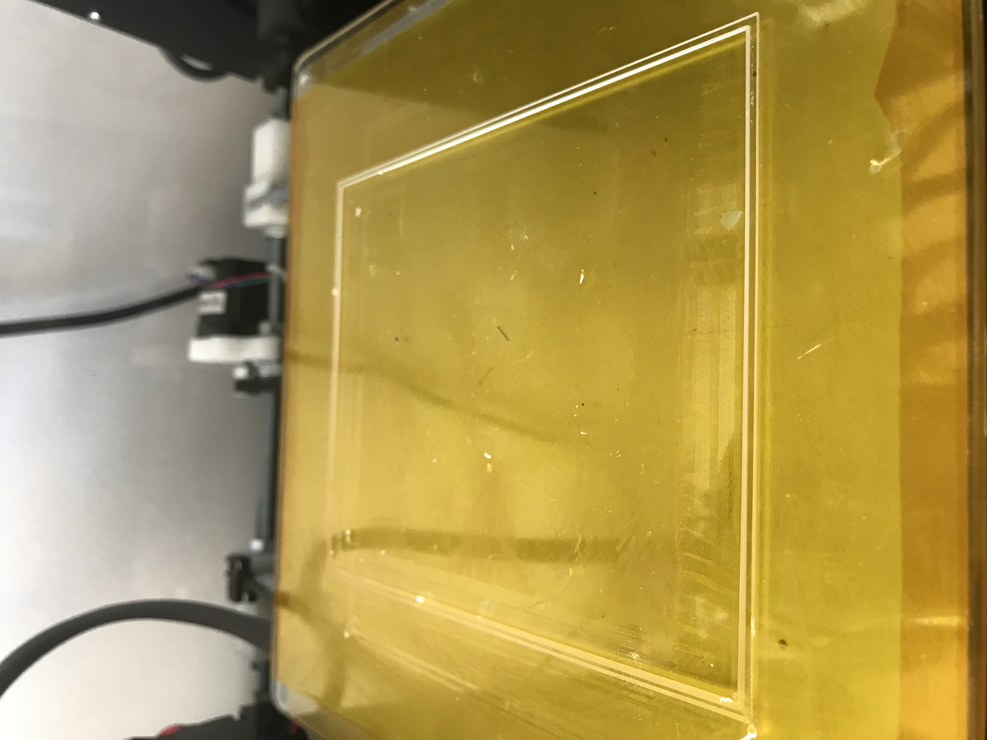
Today I decided to rotate the heat bed by 90°. My thinking was that maybe the aluminum plate is thinner on the left side and thicker on the right. So if I rotate the plate by 90° in counter clockwise direction then in theory front should be higher and the rear lower. Here is the result:
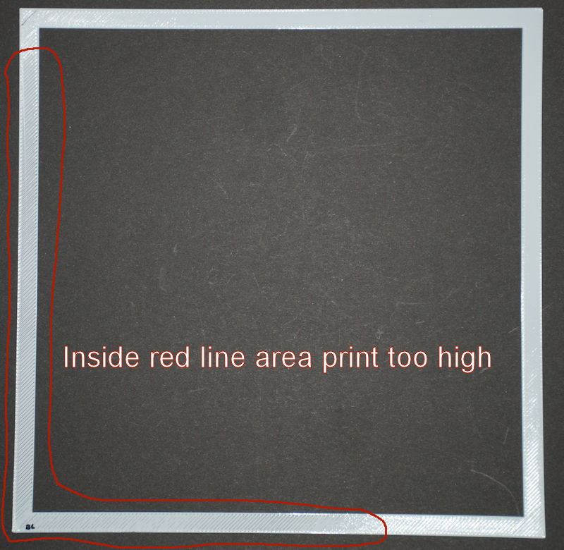
The result is not what I expected. The inside red lined area is where the print is too high. The rest of the print is where the nozzle is lower. Since their is a different pattern compared to the original tests I'm going to conclude that the aluminum plate is not the culprit.
So I'm still at a lose as to what's going on.
Lord-Quake
on 5 Nov 2017
Having G26 work for Bi-Linear would be helpful in situations like this. We would be able to see where the mesh points are too high or too low.
But that work hasn't been done yet.
Roxy-3D
on 5 Nov 2017
@Roxy-3D It's documented in my post dated Aug 12.
I've rotated the heat bed back to it's original position and did the same test again.
The result is very simular to the very first tests in this thread with the exception of the area in the upper right side.
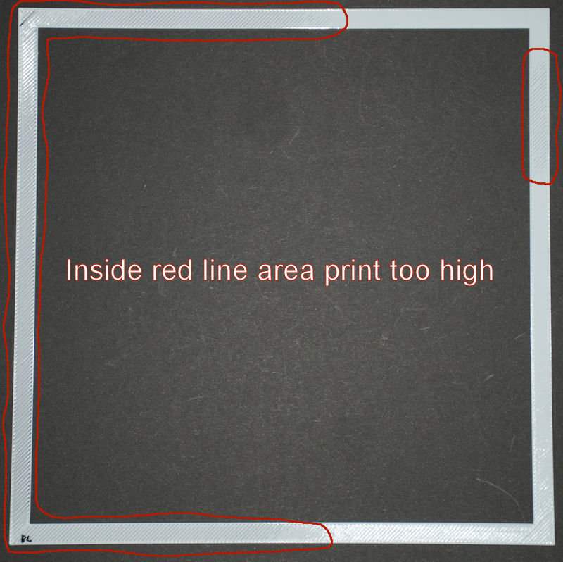
Lord-Quake
on 5 Nov 2017
It's documented in my post from Aug 12.
Yeah... But it is easier for me to understand things when we can see what the printer is doing:
In this post, you can see areas where the mesh points are too high... too low... And the ones that are correct:
https://github.com/MarlinFirmware/Marlin/issues/7927#issuecomment-338527160
Roxy-3D
on 5 Nov 2017
OK. Understood. I'll see if I can get that pattern to print on my printer.
Just for reference I've added the 9 measuring points (aprox positions) in the below picture.

Lord-Quake
on 5 Nov 2017
@Roxy-3D OK, I finally got the code compiled for use with UBL. I had to disable LCD. UBL settings are left with default values.
After homing I started "G26 R". It started printing the pattern but after a while it would print too far to the rear causing the build plate to move too far forward. I stoped the print.
Where exactly do I change the parameters so the print stays inside the build area?
As reference when I use Bilinear the settings are as follows:
#if ENABLED(AUTO_BED_LEVELING_LINEAR) || ENABLED(AUTO_BED_LEVELING_BILINEAR)

  // Set the number of grid points per dimension.
  #define GRID_MAX_POINTS_X 3
  #define GRID_MAX_POINTS_Y GRID_MAX_POINTS_X

  // Set the boundaries for probing (where the probe can reach).
  #define LEFT_PROBE_BED_POSITION 15
  #define RIGHT_PROBE_BED_POSITION 205
  #define FRONT_PROBE_BED_POSITION 15
  #define BACK_PROBE_BED_POSITION 180
It is set to the entire reachable area of the bed, -1mm on each edge by default, via the BED_SIZE and MESH_INSET, and probe offsets:
https://github.com/MarlinFirmware/Marlin/blob/bugfix-1.1.x/Marlin/Configuration.h#L944
fiveangle
on 6 Nov 2017
Thank you. I set it to 15mm and that did the trick.
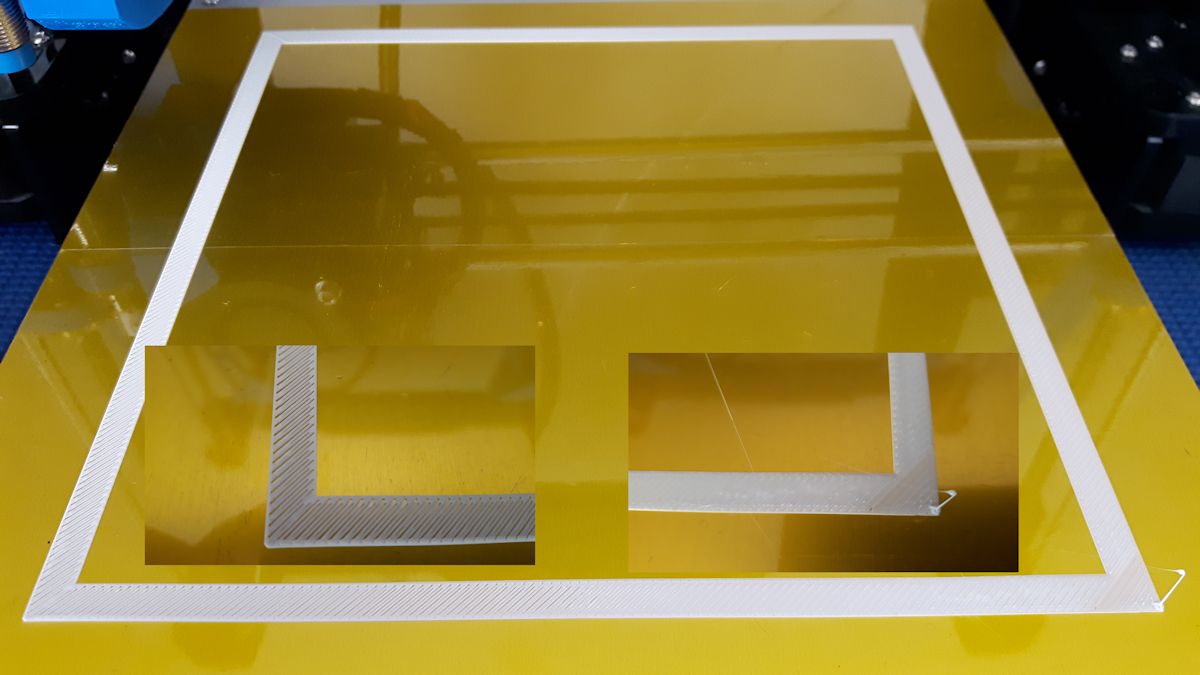
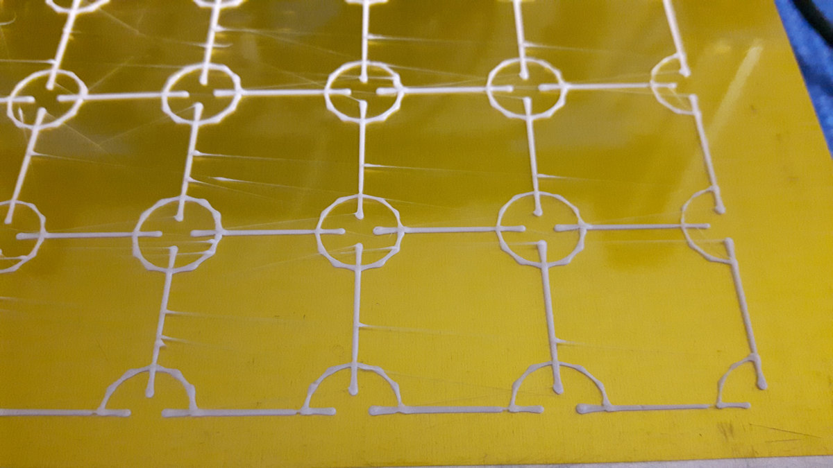
Here is the result. Ignore the blog as I primed 10mm and could not remove it quick enough.
One picture shows the whole plate, 4 corner and one center.
I'm curious as to your analysis:


Lord-Quake
on 6 Nov 2017
Good! Making progress. You have adhesion on 100% of the bed which is a little bit unusual for the first pass. One thing I notice in your pictures is you do not have some areas that are too high and some areas that are too low. Pretty much, any area that isn't "Perfect" needs the mesh points lowered. Usually that happens if the Z_PROBE_OFFSET_FROM_EXTRUDER is not quite negative enough. You might want to adjust that down .05mm and regenerate the mesh.
But if you don't want to regenerate the mesh...
In the first picture... On the edge of the mesh, it looks like the filament is not being squished into the bed. Please lower those edge mesh points .05 mm. And maybe lower the next row in by .025mm
On the second picture... My guess is lowering the first (the edge) mesh points .025mm will make the print work better.
In the 4th picture, the connecting lines between the circles look 'good'. That is what you are trying to accomplish by lowering those mesh points in the previous recommendations...
Roxy-3D
on 6 Nov 2017
Well, I have to say that I'm even more confused to what is going on simply because with the above pattern print I can't find anything wrong. Just by sight and feel I can't see any differences in height on the whole plate. This surprised me a lot.
Before I did the pattern tests I had to print an obect and had the same problems (left too high, right too low).
A can change Z_PROBE_OFFSET_FROM_EXTRUDER and set it lower but then I would have major problems on the right side when printing in Blinear mode again.
So the question is what do I need to do to get it this perfect in Blinear mode?
Lord-Quake
on 6 Nov 2017
Well, I have to say that I'm even more confused to what is going on simply because with the above pattern print I can't find anything wrong.
Yes... And that is because the mesh points are not uniform. Some are higher than others. But even so... Some small amounts of correction still needs to be made to a few of the mesh points.
Some of what I'm saying is personal preference. But I prefer the first layer is squished about like the connecting lines in the 4th picture.
Just by sight and feel I can't see any differences in height on the whole plate. This surprised me a lot.
Yes. I know. It is amazing that a 'flat' piece of glass has that much variance in it. Especially at the edges. But I can tell you... I've still not found a 'flat' piece of glass for my printer. And that is the reason the mesh based leveling systems are so popular. They can compensate for what ever funny shape the bed has.
Roxy-3D
on 6 Nov 2017
It's not glass. It's just a cheap aluminum plate with kapton tape.
Lord-Quake
on 6 Nov 2017
OK... But the point still is... Things that looks perfectly smooth to us really aren't. If you want to use Bi-Linear leveling.... It probably is still worth while to do a few G26 & UBL G29 P4 R cycles and edit the mesh to perfection. Once you have the G26 producing lines that are 'squished' the right amount everywhere, you can probably use those mesh point values for your Bi-Linear mesh.
Roxy-3D
on 6 Nov 2017
Hi guys!
Have the exact same issue. Isnt it strange that we all have different printers, heatbeds and probes, but nearly always the left side is too high?
 insanity67
on 25 Jun 2018
insanity67
on 25 Jun 2018
Yep, that’s what always amazed me, always left, always high. I bet I’ve run
that routine 30 times and always the same result. Sometime better, sometime
worse, but always high. The opposite side is darn near perfect.
On Mon, Jun 25, 2018 at 4:11 PM insanity67 notifications@github.com wrote:
Hi guys!
Have the exact same issue. Isnt it strange that we all have different
printers, heatbeds and probes, but nearly always the left side is too high?—
You are receiving this because you were mentioned.
Reply to this email directly, view it on GitHub
https://github.com/MarlinFirmware/Marlin/issues/7278#issuecomment-400079712,
or mute the thread
https://github.com/notifications/unsubscribe-auth/ARvmpNrnZB8LKBEmv6zsmkCAX9NiBj_zks5uAUP7gaJpZM4OUkyd
.
BillyBob54
on 26 Jun 2018
nearly always the left side is too high
Compare the mesh generated through AUTO_BED_LEVELING_BILINEAR to the mesh that you get using MESH_BED_LEVELING. If they are nearly identical, we should look further.
thinkyhead
on 26 Jun 2018
This issue has been automatically locked since there has not been any recent activity after it was closed. Please open a new issue for related bugs.
![github-actions[bot] picture](https://avatars2.githubusercontent.com/in/15368?v=4&s=40) github-actions[bot]
on 19 Aug 2020
github-actions[bot]
on 19 Aug 2020
Related issues
 StefanBruens
·
4Comments
StefanBruens
·
4Comments
 heming3501
·
4Comments
heming3501
·
4Comments
 pubalan12
·
4Comments
pubalan12
·
4Comments
 Ciev
·
3Comments
Ciev
·
3Comments
 otisczech
·
3Comments
otisczech
·
3Comments
Most helpful comment
Really fat fingered the last comment :-O; fixed the typos; that’s what I get for trying to type and walk at the same time- good thing I wasn't chewing gum as well!!!!