Marlin: The Marlin 2.0 32-bit thread
Board|MCU|State|To-Do
-|-|-|-
8-Bit AVR boards, RAMPS, etc.|Arduino AVR|💚good|
Due, RAMPS FD (v2.A!), etc.|SAM3X8E|💚good|
Duet Wifi + X5|SAM3X8E|❓unknown|E3D Toolchanger on hand
Duet 2 Maestro|SAM3X8E|⚠️beta|
Archim 1.0|SAM3X8E|❓unknown|Only US$170!
Archim 2.0|SAM3X8E|💚beta|needs confirmation
Grand Central|ATSAMD51|🛑tbd|(RAMPS_FD shield should work)
Re-ARM|LPC1768|💚beta|
MKS-SBASE|LPC1768|💚beta|
Smoothieboard|LPC1769|💚beta|
Azteeg X5 GT|LPC1769|💚beta|
Cohesion3D Remix|LPC1769|💚beta|
Selena Compact|LPC1768|💚beta|
Malyan M200|STM32F103C8|💚beta|EMERGENCY_PARSER,NEOPIXEL_LED, etc.
Borg|STM32F765ZGT6|⚠️beta|EMERGENCY_PARSER,NEOPIXEL_LED, etc.
Chitu3D V3.9|STM32F103ZET6|🛑alpha|EMERGENCY_PARSER,NEOPIXEL_LED, LCD, SDCard, MAX6675, etc.
Teensy 3.5|MK64FX|⚠️beta|(need shields)
Teensy 3.6|MK66FX|⚠️beta|(need shields)
Espressif 32 Wifi|ESP32|⚠️beta|(mostly working?)
STEVAL-3DP001V1|STM32F401VE|🛑alpha|(need boards)
- Good: All features working.
- Beta: All features implemented, mostly working.
- Alpha: Some features unimplemented/broken.
This thread is for discussion of 32-bit issues needing work and coordination of the 2.0 release.
 thinkyhead
All 1715 comments
It's not easy to stop the flow of issues, and we want to keep fixing any bugs that exist in 1.1, of course. So I propose that we take care of the current crop of obvious bugs —and only bugs— do a 1.1.4 release very soon, and one more release —1.1.5— just before we release 1.2.x, the new hierarchical + HAL version of Marlin.
@Tannoo and I have some clean up work going for the LCD header files. As it turns out... The .h files can only be included by one .cpp file because the .h files generate code. While this is not a 'bug fix' it is an important item from a 'code cleanliness' perspective.
We have the Graphical LCD Display code clean up done. The 20x4 LCD Display clean up should progress quickly. https://github.com/Tannoo/Marlin/tree/ultralcd_impl_DOGM.cpp
 Roxy-3D
on 16 Jun 2017
Roxy-3D
on 16 Jun 2017
 Tannoo
on 16 Jun 2017
Tannoo
on 16 Jun 2017
Release 1.2 (or Marlin 2.0?) with the hierarchical layout, support for some 32-bit boards.
Go with v2.0.
Support for 32bit platforms will indicate a new era for Marlin and for sure will warrant a tick in the major version count.
 teemuatlut
on 16 Jun 2017
teemuatlut
on 16 Jun 2017
We have the Graphical LCD Display code clean up done. The 20x4 LCD Display clean up should progress quickly. https://github.com/Tannoo/Marlin/tree/ultralcd_impl_DOGM.cpp
Both the Graphical LCD Panel and the 20x4 LCD Panel .h files are cleaned up in this branch...
Tannoo is going to get the indentation and white space cleaned up....
Roxy-3D
on 17 Jun 2017
The .h files can only be included by one .cpp file because the .h files generate code.
That is correct. The LCD-oriented header files may only be included once, and only in ultralcd.cpp. They are essentially just .cpp files, but given .h extensions so that they don't compile outside of ultralcd.cpp.
We could make them into proper .cpp files and fix the unorthodox usage, without any negative affect on performance, but let's wait till @Tannoo's changes are ready.
thinkyhead
on 17 Jun 2017
Is the new file structure going to allow Marlin to use a single file for Configuration? Much like Smoothieware? Is that one of the immediate benefits of doing this, apart from 32 bit and HAL
?
 ImplementOfWar
on 17 Jun 2017
ImplementOfWar
on 17 Jun 2017
@ImplementOfWar That has not been discussed yet. Smoothieware is able to do certain things by limiting itself to 32-bit boards which have far greater resources. When and if someone implements a configuration system in emulation of Smoothieware, it will have to be for 32-bit boards only.
thinkyhead
on 17 Jun 2017
@thinkyhead What are you thinking for a time table to lock down the code?
I thought I could get the ultralcd_impl_HD44780.h separated into declarations and code generation... But it is turning out to be worse than I expected. We have the DOGM stuff separated, so that is a start. But the 20x4 LCD code is especially bad. It is very very ugly...
So, we could just go with what we have... Or... You can take a look at where we are at: https://github.com/Tannoo/Marlin/tree/ultralcd_impl_DOGM.cpp and see if you can figure out the issues?
Roxy-3D
on 17 Jun 2017
You can take a look at where we are at: https://github.com/Tannoo/Marlin/tree/ultralcd_impl_DOGM.cpp
https://github.com/Tannoo/Marlin/tree/LCD_Interactive_Mesh_Edit_Refinements
Tannoo
on 18 Jun 2017
I should delete the ultralcd_impl_DOGM.cpp branch. It was created as a test bed for the splitting of the DOGM.h file.
Tannoo
on 18 Jun 2017
We should probably ping the whole @MarlinFirmware/language-team to complete translations.
 petrzjunior
on 18 Jun 2017
petrzjunior
on 18 Jun 2017
Do I understand correctly that the new features will not be added before the release of version 2.0 (1.2)?
If so, when can we expect 2.0?
What about PRs that were created before the decision was made?
 fixoid
on 18 Jun 2017
fixoid
on 18 Jun 2017
What about the PRs that were created before the decision was made?
In general... The Pull Requests generate for the current organization that do not make it into the new file layout should not be that difficult to regenerate. The bulk of the files are not going to change. What may change are things like paths to header files or stuff like that. If your Pull Request doesn't make it to the new layout automatically... It will be very straight forward to regenerate it.
Roxy-3D
on 18 Jun 2017
thought I could get the ultralcd_impl_HD44780.h separated into declarations and code generation... But it is turning out to be worse than I expected.
The ultralcd_impl_* files were never designed to be standalone, but are really just split out parts of ultralcd.cpp. It would be best to wait till the ultralcd code is converted to a singleton class, and rearrange anything needing rearranging at that time. It will make more sense once it's examined in terms of a class — and ultralcd_impl_* may end up as two instances of a helper class. Or there may be other separation of functionality into more classes. It's something I want to work on more comprehensively, immediately after rearranging the code and getting the HAL working. And I'm pretty sure the LCD menu code can be simplified somewhat also.
thinkyhead
on 19 Jun 2017
Do I understand correctly that the new features will not be added before the release of version 2.0 (1.2)?
Halt means halt. If a larger number of contributors would like to help get the existing PRs merged, that would be an excellent change of pace. There's a lot of backlog to take care of.
If so, when can we expect 2.0?
As soon as I can get it together.
What about PRs that were created before the decision was made?
There's nothing to be done about it. There will never be some point in time where every PR will be merged, so it's best to stop the flow of new PRs and work on the PRs that we already have in front of us. I have been trying to get as many merged as possible, but more keep coming in. And so, we just have to go for it and it's just unfortunate timing for any PRs that will need to be reworked.
As it is, it will be me who has to re-work all the existing PRs into the new layout, because I have the mojo to make that happen as quickly as possible, and I will have all contingencies freshly in mind.
thinkyhead
on 19 Jun 2017
What are you thinking for a time table to lock down the code?
Let's keep fixing bugs all the live long day. Simply don't merge new stuff, and put off new features. If any new features come in while we're working on the transition, we'll simply put them off. Most contributions will be straightforward enough that it will be easy to re-make them for the new layout. Some we may have to work on within the old layout first, then when ready also bring them to the new layout.
We should continue to fix bugs in the 1.1.x branch and I will make sure they are brought into the new layout as well.
As for a timetable, I think we need to go in two stages. First, since we have so much work being done to make the 32-bit code ready, perhaps we should get that into minimal working shape first. Then I can include a genuine HAL as part of the initial 2.0.x branch.
The layout conversion itself isn't hard. The first conversion will take me less than a day to complete, and then we can go over it and see where it needs tweaking.
I'd like to focus on going over the open issues for the next day or two, patch up as many obvious bugs as possible, and merge as many of the lingering PRs as possible. One of PRs contains the 32-bit HAL rebased on the latest bugfix-1.1.x and that will also need to be brought up to date — though not merged with any Marlin 1.1.x.
Once the HAL is working and we're happy with it, then I'll rebase it onto the latest code and use that as the starting-point for Marlin 2.0 with the new file layout.
I think it's a good idea to take the next few days and close as many issues as we can so we have a fresh start.
Yes, it's possible that we could have a 2.0 layout and initial release by the end of the week… but let's loosen up the schedule so we can clear as many issues as possible and just aim to have it ready by July 1. How does that sound?
thinkyhead
on 19 Jun 2017
Yes, it's possible that we could have a 2.0 layout and initial release by the end of the week… but let's loosen up the schedule so we can clear as many issues as possible and just aim to have it ready by July 1. How does that sound?
_July 1st sounds fine... Especially if there is a sample 32-Bit HAL limping along and able to move the nozzle around!!!_
Roxy-3D
on 19 Jun 2017
@Roxy-3D I'm pretty sure all the platforms currently in the HAL can do that, if the board supports the Arduino framework it's fairly trivial to implement basic features, the main stumbling block for non Arduino framework devices is the extra features needing Arduino libraries or Classes. I should be able to print tonight on my Re-ARM but the HAL needs further extended to strip all Arduino based features out of the main code and behind an API this will need to be done incrementally once we get the HAL merged.
 p3p
on 19 Jun 2017
p3p
on 19 Jun 2017
I should be able to print tonight on my Re-ARM but the HAL needs further extended to strip all Arduino based features out of the main code and behind an API this will need to be done incrementally once we get the HAL merged.
What classes and functions are you missing? Would it be possible to just pull in the Arduino libraries so we don't have duplicated code complicating things?
Roxy-3D
on 19 Jun 2017
Things like Print and Wire (as two random examples), just generally anything that is from the Arduino framework will need to be abstracted, this won't lead to code duplication and should lead to much cleaner and more understandable code, anything that can use the Arduino framework still can, although sometimes it may turn out it wasn't even necessary just convenient when it was implemented.
In some cases it may be difficult without introducing some indirection overhead, but anything performance critical already avoids the Arduino framework. It may be a good idea to have folders in the HAL (arduino_framework, mbed_framework) devoted to anything that can be reused among platforms that use that framework, but that's probably discussion for another day.
p3p
on 19 Jun 2017
It may be a good idea to have folders in the HAL (arduino_framework, mbed_framework) devoted to anything that can be reused among platforms that use that framework, but that's probably discussion for another day.
@thinkyhead @p3p Well... Right now is a good time to express opinions and recommendations. It may not be too hard to get the HAL folders setup logically from the very start. But any subsequent, improved layout and organization for the HAL's will be welcomed also.
Roxy-3D
on 19 Jun 2017
Would it be possible to just pull in the Arduino libraries so we don't have duplicated code complicating things
In the case of Wire all Arduino based platforms could still use it, but the calls would be through a standard API such as i2c_begin(channel, address), i2c_send_byte(channel, data), that other platforms would implement themselves or through another framework.
p3p
on 19 Jun 2017
What can I do to help with this effort? I've got a bit of free time in the evenings this week, so I'm happy to help out if I can.
 tcm0116
on 20 Jun 2017
tcm0116
on 20 Jun 2017
I think it is a little too early to do anything. We need the new organization to happen and be in place. But as soon as that happens... Several important items are on the list:
- Simple, step by step directions for getting the firmware onto a Re-ARM board. (Using Cygwin in a Windows environment would be preferable, but if we have to bring up a Linux machine, that would be tolerable.)
-- Any extra configuration required.
-- Steps to compile and build image outside of Arduino
-- Steps to flash including notes on using the 2nd USB port
-- Etc. - Simple, step by step directions for getting the firmware onto other 32-Bit boards.
- It maybe good to have a thread showing how far the boot process is working for each 32-bit board type. And what sub-systems of Marlin still need attention for the board.
- It will also be good to have the 32-Bit developers look at the new layout and suggest changes (and submit Pull Requests) to organize things better for themselves.
I believe there is a lot of pent up demand for an official 32-Bit version of Marlin. If we can just get one board up and working with the new release, and clear instructions so anybody can duplicate the success... We should see a lot of activity. And my guess is a number of different 32-Bit boards will start to have people using them.
Roxy-3D
on 20 Jun 2017
This information is very old, please use the official bugfix-2.0.x branch and using platformio build for LPC1768 if you have a Re-ARM board
Simple, step by step directions for getting the firmware onto a Re-ARM board.
1: Clone https://github.com/p3p/Marlin.git and checkout branch 32bit-bugfix-1.1.x-LPC1768
2: Install PlatformIO IDE
3: Open project in PlatformIO and build for Re-ARM (click bottom left of screen and scroll to bottom of options)
4: Copy firmware (
I've maintained compatibility with the Arduino pin layout so the same pins files should work (tested with RAMPS14).
This is a work in progress so once Marlin is flashed to the Re-ARM you lose access over usb to serial and the micro sd card, you will need another means of accessing the sdcard and an ftdi cable to access the 6 pin hardware serial port on the Re-ARM.
As of today I'm printing* with Re-ARM, steppers, heaters, ADC, SD card and graphical controller all work (character displays probably will not, they are more closely integrating with Arduino) using my RAMPS14, so basic functionality is at least out of the way.
p3p
on 20 Jun 2017
@p3p THANK YOU SO MUCH! I'm going to start messing with getting some simple firmware compiled and loaded into a Re-ARM board using your steps... I'll at least be in a position to start messing with different things when the time comes!
Roxy-3D
on 20 Jun 2017
@p3p Up above you say to 'build for Re-ARM'. I can't find that in the list. But I did find Platform NXPLPC NXP mbed LPC1768. Is that the correct selction for the Re-ARM board?
I'm also having trouble getting the project to open up in PlatformIO. But I did get something to happen when I dragged and dropped the platformio.ini file onto my Atom icon on the desk top. A little more info on what I do to open the project would be helpful too!
Roxy-3D
on 20 Jun 2017
I too am having trouble.
Though we might need to generate a platform specifically for the Re-ARM
http://docs.platformio.org/en/latest/platforms/creating_board.html
 Grogyan
on 20 Jun 2017
Grogyan
on 20 Jun 2017
When you open Atom it should open onto a Home screen, one of the Quick Access options is to "Open Project" if you browse to the folder containing platformio.ini and click open, in the left panel you should get the Marlin project file listing (.github, buildroot, &c.) from here you should be able to click the PIO build in the bottom corner and scroll down to Re-ARM
p3p
on 20 Jun 2017
Though we might need to generate a platform specifically for the Re-ARM
Using the LPC1768 board with a modified linker script for compatibility with the smoothieware bootloader works well for now but we could do that in the future. The Re-ARM build is defined in the platformio.ini file so as long as you have correctly checked out the branch it should be there.
p3p
on 20 Jun 2017
Thanks Chris,
Posting a couple of screenies to help others
https://user-images.githubusercontent.com/6621978/27358346-49d44a66-566a-11e7-9e48-77e386830f93.png
https://user-images.githubusercontent.com/6621978/27358349-517a2268-566a-11e7-88be-2c1e29771f31.png
Grogyan
on 21 Jun 2017
Ooooops! I managed to do a Re-ARM Upload. But I had my Atmega2560 with a RAMPS board plugged in.... My LCD screen went crazy.
THANKS p3p!!!
Roxy-3D
on 21 Jun 2017
Just don't expect too much when (if) you get it on the hardware I only got the heaters working this afternoon ^^ and if you change the config it will probably explode .. I also just noticed an issue with corruption in the serial data during a test so that's my task tonight (he says at 23:30)
p3p
on 21 Jun 2017
Yeah... Don't worry about that! I'm just trying to get up the learning curve because my guess is when we get the new file layout, progress is going to be made fast. I don't want to be left behind.
So... I'm going to be playing with a lot of stuff. Mostly simple stuff. But I want to understand all the steps and how the development environment works. And then... Who knows, maybe I can help with some of the simpler stuff like getting the 20x4 LCD Displays working.
The point is, when 32-Bit progress can be made against the current code base, eventually.... everything will be working even though the code base kept evolving as that was happening. And if people can run the current code base on 32-Bit platforms... More and more people will jump on-board.
Roxy-3D
on 21 Jun 2017
Hey @Roxy-3D is that Ray Cortes kickstarter board?
https://www.kickstarter.com/projects/1245051645/re-arm-for-ramps-simple-32-bit-upgrade
I did order it for $48 for my 3D printer and it's gathering dust at the
moment. I would be really interested to see this getting of the ground. I'm
doing a kickstarter for my Gerbil K40 laser controller at the end of the
month so I cannot contribute much but I'm eager to learn how to port code
to this environment. Where can I follow it in detail?
On 21 June 2017 at 08:47, Roxy-3D notifications@github.com wrote:
Yeah... Don't worry about that! I'm just trying to get up the learning
curve because my guess is when we get the new file layout, progress is
going to be made fast. I don't want to be left behind.So... I'm going to be playing with a lot of stuff. Mostly simple stuff.
But I want to understand all the steps and how the development environment
works. And then... Who knows, maybe I can help with some of the simpler
stuff like getting the 20x4 LCD Displays working.The point is, when 32-Bit progress can be made against the current code
base, eventually.... everything will be working even though the code base
kept evolving as that was happening. And if people can run the current code
base on 32-Bit platforms... More and more people will jump on-board.—
You are receiving this because you are on a team that was mentioned.
Reply to this email directly, view it on GitHub
https://github.com/MarlinFirmware/Marlin/issues/7076#issuecomment-309913380,
or mute the thread
https://github.com/notifications/unsubscribe-auth/AIOTKVmipb4ymHxTHrBPpX65nKSnQTPDks5sGEwBgaJpZM4N82_j
.
 paulusjacobus
on 21 Jun 2017
paulusjacobus
on 21 Jun 2017
It is not Ray's board. I have that on my desk too. But I'm trying to learn how to generate code with the PlatformIO IDE.
@p3p I obviously don't understand something... I thought I built the firmware OK, and put it on the SD Memory card. But nothing happened on the Graphical LCD Panel when I started up the board. So I'm not sure what I'm fighting and decided to just try to make an LED blink. I added this code to Marlin_main.cpp
void pinMode(int pin, int mode);
void digitalWrite(int pin, int pin_status);
bool digitalRead(int pin);
void analogWrite(int pin, int pin_status);
uint16_t analogRead(int adc_pin);

void setup_LEDs() {
int p, r, t, s;

    for(p=1; p<54; p++) {
        pinMode(p, OUTPUT);
    for(r=0; r<10; r++) {
            digitalWrite(p, LOW);  // drive it down
        s = 0;
        for(t=0; t<5000; t++) {
            s=s+digitalRead(20)&0x01;
            }
            digitalWrite(p, HIGH);  // drive it up
        for(t=0; t<5000; t++) {
            s=s+digitalRead(20)&0x01;
            }
            digitalWrite(p, LOW);  // drive it down
    }
        pinMode(p, INPUT);
    }
}
and then in the setup() function I called it:
void setup() {

  #ifdef DISABLE_JTAG
    // Disable JTAG on AT90USB chips to free up pins for IO
    MCUCR = 0x80;
    MCUCR = 0x80;
  #endif

  #if ENABLED(FILAMENT_RUNOUT_SENSOR)
    setup_filrunoutpin();
  #endif

  setup_LEDs();
I have LED's plugged into different places on the Re-ARM board. (Right now, what would be pins 1,2 and 3 on an ATMega-2560 board) and I do see some changes in them when I reset the board. But I don't get on and off blinks like I expect. Obviously, I'm missing something. Can you change the setup_LEDs() so it blinks an LED for me? With that I'll be able to make a lot more progress.
Roxy-3D
on 21 Jun 2017
Without the serial connection it will be hard to know what went wrong, can you confirm the firmware was written correctly, the Re-ARM renames "firmware.bin" to "firmware.cur" after flashing. Assuming that's correct you should at least get serial output (and the logo if the config is compatible with your setup).
p3p
on 21 Jun 2017
Without the serial connection it will be hard to know what went wrong, can you confirm the firmware was written correctly, the Re-ARM renames "firmware.bin" to "firmware.cur" after flashing.
Yes... It is renaming the file.
Assuming that's correct you should at least get serial output (and the logo if the config is compatible with your setup).
I do not have the board connected up to any endstops or stepper motors yet. And I maybe fighting the problem where some graphical displays have reversed cables. I don't know what I'm fighting. That is why I thought I would start small and try to blink an LED. But I can't even make that happen right now. So I have a pretty big learning curve in front of me.
It appears you re-mapped the ReARM connector locations to match the Atmega2560/RAMPS board locations... I'm getting a lot of warnings when trying to use that code. I found the documentation showing the Re-ARM Port and Pin numbers.... I can go after those LED's in the Re-ARM's address space now. And then migrate back to the RAMPS locations...
Don't worry about me... I'll figure it out.
Roxy-3D
on 21 Jun 2017
The functions (digitalWrite, pinMode ect) that I wrote make the pin mapping transparent, you just use them as you would on Arduino Mega, not all pins have been mapped yet (or can be) pinmap_re_arm.h controls that.
With nothing plugged into the Re-ARM it should still boot up into Marlin and you can control it via the serial port, without more information about what is being output I can't really help, Displays and controllers I wasn't expecting just to work unless they are identical to reprap full graphic smart controller.
If you don't have a ftdi cable you can forward the serial through an Arduino but I recommend getting one they come in handy.
p3p
on 21 Jun 2017
I just realised you didn't say if the LCD display was powering up or that you used the adaptor cable from http://www.panucatt.com/product_p/glcd-idc.htm to connect it, all that cable does is split pin 1 off so you can connect it to a 5v pin on the Re-ARM.
If you do want to run code on the Re-ARM without any of Marlin getting in the way, there is a main function in HAL.cpp that calls setup and loop just comment them out. From there you should at least be able to toggle Digital outputs for testing.
p3p
on 21 Jun 2017
I do get the Graphics LCD Screen to light up. (RepRap Discount Full Graphic Smart Controller)
I have the split cable and apparently did get the +5 volt wire to work. I just don't have anything being displayed on it (yet). I'll keep plugging away.
And I just brought the LCD Panel up on an ATMega2560 board... So I have the cable correct.... Next I'll move things over to the LPC1768
Roxy-3D
on 21 Jun 2017
I'll try to apply the new file layout incorporating the HAL this weekend and post a 2.0.x branch that we can patch up for release. This will just be a first attempt, and can be reworked as needed.
We might still have too many open issues needing fixing before we jump ahead, but at least this will provide a starting point. I haven't counted open issues lately, but I will do an audit and try to produce a list of lingering bugs and issues that we should fix ahead of the new layout.
thinkyhead
on 22 Jun 2017
We might still have too many open issues needing fixing before we jump ahead, but at least this will provide a starting point. I haven't counted open issues lately, but I will do an audit and try to produce a list of lingering bugs and issues that we should fix ahead of the new layout.
@thinkyhead From reading all the new issues and posts to them... There doesn't seem to be anything critical. We have a few questions about BL-Touch probes not working. We have a couple of bed leveling issues across the spectrum of different bed leveling schemes. But nothing dire.
My suggestion would be, we cut and run. Until the new folder and file layout is complete, people can just continue with today's bugfix-v1.1.x .
Roxy-3D
on 22 Jun 2017
@thinkyhead @p3p I moved the LPC1768 changes for the Re-ARM board over to 32-Bit-RCBugFix-new just to make sure they don't get forgotten! We need p3p's LPC1768 stuff in the new file & folder layout.
It isn't passing the Travis tests... But it is here as a Pull Request: https://github.com/MarlinFirmware/Marlin/pull/7121 I wonder if we should merge it anyway just to make sure it is part of the mix?
Roxy-3D
on 23 Jun 2017
Now that the bugfix-2.0.x branch has been created, we can try to bring over the elements from oh-so-older 32-Bit-RCBugFix-new branch, including your new changes in #7121, if they're ready for inclusion and/or consistent with the HAL stuff from @teemuatlut and @p3p.
I'd like to get the HAL elements pretty well organized ahead of the rest of the code reorganization, since all other components will depend on it.
thinkyhead
on 27 Jul 2017
@thinkyhead The new branch was based on 32-Bit-RCBugFix-new so I'm relatively sure there is nothing missing that was in there (although I seem to remember there was some issue rebasing @teemuatlut's PIN DEBUG code), I was back-porting anything that was general HAL from the LPC1768 branch into the PR but I do have to finish the new SPI integration (I have to implement it for the other platforms), then I would like to continue moving the HAL features into the HAL::Feature naming convention (HAL::ADC , HAL::I2C, ect) with general headers.
p3p
on 27 Jul 2017
You can leave the pins debug for Teensies in whatever state. I'll go over it once everything has settled down.
teemuatlut
on 27 Jul 2017
@thinkyhead You said in the first post that the aim for 1.1.5 was to fix all obvious bugs.. well dual X carriage has been broken since 1.1.1. See #6956 #7050 #7291.
 oysteinkrog
on 28 Jul 2017
oysteinkrog
on 28 Jul 2017
I may be interested in finding a fix for this as I'm building a dual X machine myself, but I can only get to it next week so if it's not solved by then I'll take a crack at it. Further discussion should be made on #7291
teemuatlut
on 28 Jul 2017
@teemuatlut I've tracked down the problem and I have submitted a PR that fixes it. It's great to have more people with DUAL_X_CARRIAGE though as I'm pretty sure there are still bugs related to it.
oysteinkrog
on 31 Jul 2017
Good to hear.
teemuatlut
on 31 Jul 2017
Hi, I have dual X carriage printers with RADDS / Due + RADDS LCD Display with SD card.
What LCD option do I select in Marlin2
Thanks - bruce
 bruce356
on 10 Aug 2017
bruce356
on 10 Aug 2017
Is Marlin 2.0 compatible or intended to be compatible with the Azteeg x5 mini? (LPC1769)
https://www.matterhackers.com/store/printer-accessories/azteeg-x5-mini-32bit-all-in-one-controller-v1.1
 klcjr89
on 10 Aug 2017
klcjr89
on 10 Aug 2017
Is Marlin 2.0 compatible or intended to be compatible with the Azteeq x5 mini? (LPC1769)
Right now, the bulk of the 32-bit activity is on the Panucatt Re-ARM board. That uses a LPC-1768 which is very similar to the LPC-1769. The way the code is being done, the current work should move over to that board with a minimum of effort. If pins are assigned differently, they would just get moved around in a mapping table. And the LPC-1769 is faster so some timer speeds would shift.
Incidentally, Panucatt supplied us with enough Re-ARM boards to get critical mass on the development side. It kind of feels like they want the X5 (and the X5 mini) to support Marlin so that will probably happen as soon as the Re-ARM board is solid. And it might even be possible to make the required changes without connecting an X5 up to a printer. But that remains to be seen...
Roxy-3D
on 10 Aug 2017
I'm very happy to hear this. The X5 is the board I want to use. I may have to drop Roy an email to get things rolling on purchasing a couple of them.
 mperdue
on 10 Aug 2017
mperdue
on 10 Aug 2017
If you want to order a single X5 board and get it connected up to a printer... People in this thread should be able to tell you what to edit on the Re-ARM code to make it work with the X5: https://github.com/MarlinFirmware/Marlin/pull/7390
Roxy-3D
on 10 Aug 2017
Sounds like a good plan. I'll see about getting one on order shortly. I might have to grab some spare parts and put together a functional 3D printer setup for testing.
mperdue
on 10 Aug 2017
And probably... At least from my perspective... I think it is likely the Re-ARM HAL goes away and we have a single LPC-1768(9) HAL. Probably, the changes to the Re-ARM code is very minor to make it work on the X5 board. BUT... That remains to be seen.
Roxy-3D
on 10 Aug 2017
In theory the firmware will run as is on an LPC1769 they are binary compatible, but the pins will more than likely be completely wrong.
I did take into account that there would be multiple boards running on the LPC17xx HAL (mostly), there are a few things that will need written for the X5 but are already split out in a way that should make it pretty simple. An internal pin-mapping file will be needed (pinmap_re_arm.h), and the Marlin pin-mapping (pins_RAMPS_RE_ARM.h), the linker script should be fine as should the startup assembly but the System init function will need to detect it's running on an LPC1769 and set the clock appropriately for full support.
p3p
on 10 Aug 2017
You said in the first post that the aim for 1.1.5 was to fix all obvious bugs.. well dual X carriage has been broken since 1.1.1
You can find more recent threads where it was debugged and eventually fixed. If it has become broken again (a regression) then please post a new issue detailing the exact problem(s) seen.
thinkyhead
on 10 Aug 2017
You can find more recent threads where it was debugged and eventually fixed.
He's the one who fixed it =)
teemuatlut
on 10 Aug 2017
I accidentally overwrote the bugfix-2.0.x branch a little while ago.
If the last commit was https://github.com/MarlinFirmware/Marlin/commit/c587d27 then no worries… everything is already restored.
If there's some other commit I missed, let me know.
thinkyhead
on 10 Aug 2017
I should have the X5 GT next week. This will be interesting.
mperdue
on 10 Aug 2017
I hadn't thought about this before now but will the Arduino IDE be enough to work with the X5 or do I need to get a different setup going?
mperdue
on 11 Aug 2017
I hadn't thought about this before now but will the Arduino IDE be enough to work with the X5 or do I need to get a different setup going?
You need to bring up the PlatformIO-IDE which runs inside of Atom. That will take you a few days. It is very slow to install. And it isn't intuitive to use. You will want to pull down the bugfix-2.0.0 branch and compile that for Re-Arm when you have PlatformIO-IDE installed.
Then you can start making the tweaks to shift from Re-ARM to the X5-GT.
Roxy-3D
on 11 Aug 2017
@thinkyhead Does Marlin2 support the RADDS LCD Display with SD card controller, if so which option do I select as I do not see it listed, under "// CONTROLLER TYPE: Standard".
I know I am not a developer here, but would like to test the new marlin with RADDS and X2 on my machine. I am assuming the X2 problem has been rectified.
https://github.com/MarlinFirmware/Marlin/issues/7291
bruce356
on 11 Aug 2017
@mperdue - You'll need to create a new pins_YOUR_BOARD.h file. I expect that 99% of the pin mapping can be done there. The remainder will require changes to the file pinmap_re_arm.h in the directory Marlin\src\HAL\HAL_LPC1768\pinmap_re_arm.h. You'll also need to modify boards.h and pins.h to add your board to the list of acceptable boards.
The timers won't need to be touched.
Installing PlatformIO is tedious but not hard. In Atom go to the FILE -> SETTINGS -> Install and search for PlatformIO.. You'll want to install platformio-ide, build-platformio and platformio-ide-terminal. platformio-ide takes a while to install and many (4?) restarts of Atom. Wouldn't hurt to do a couple extra restarts of Atom after it stops requesting restarts.
Once the PlatformIO home/welcome page is displayed
Click on the +New Project button. Select Other under Chose the directory and then enter the directory ABOVE Marlin.
Click -- choose a board -- and scroll down to the Platform NXPLPC area and click on NXP mbed LPC1768.
Click the Process button. Hopefully no errors will pop up.
In the extreme lower left corner of the Atom window there should be something with PIO Build in it. Click on that.
In the window that pops up enter Re-ARM in the search window.
Click on PIO Build (Re-ARM). That'll open up a window where it will show the compiler output.
If you have some compiler errors the window will stay open. Make your corrections and then, to re-run the compiler, click the lightning bolt button on the upper right of the window.
Once it says SUCCESS the executable will be the file firmware.bin in the directory .pioenvs\Re-ARM. Copy that to an SD card and insert in into the SD card reader on the motherboard. After cycling power (reset won't do it) the new code will be loaded and run.
 Bob-the-Kuhn
on 11 Aug 2017
Bob-the-Kuhn
on 11 Aug 2017
Reset does work for me.
Tannoo
on 11 Aug 2017
Unfortunately, when I hit Process I get _Uncaught ReferenceError: assignHooks is not defined_
It's the story of my life...
mperdue
on 11 Aug 2017
Oh, and the steps are a bit different on a Mac but you certainly got me pointed in the right direction.
mperdue
on 11 Aug 2017
Once the PlatformIO home/welcome page is displayed
Click on the +New Project button. Select Other under Chose the directory and then enter the directory ABOVE Marlin.
Click -- choose a board -- and scroll down to the Platform NXPLPC area and click on NXP mbed LPC1768.
Click the Process button. Hopefully no errors will pop up.
That seems an odd way of opening the project, it should just require clicking Open Project then selecting the directory with platformio.ini in.
p3p
on 11 Aug 2017
Sometimes uninstalling then reinstalling platformIO fixes that, sometimes it doesn't.
Did the project folder/directory open? If not got to File -> Add Project Folder and open it.
Try clicking on the PIO Build and see if you can search for the Re-ARM board. If you find it then you probably do a build.
On the left side of the PlatformIO home/welcome screen is a Boards button. Click on that and then search for 1768. Click on the NXP mbed LPC1768 entry. That may also get things linked up.
@Roxy - I can't find the thread that details all our trials & tribulations with platformIO. Can you point us to it?
Roxy edit >>>---> I think this is the start of where I started using PlatformIO and of course.... I had a ton of questions: https://github.com/MarlinFirmware/Marlin/pull/7028#issuecomment-315617978
Bob-the-Kuhn
on 11 Aug 2017
I found that just opening the project as suggested by @p3p worked OK and I was able to build it. Now I just need to figure out where the .bin file gets put on the Mac...
Roxy edit >>>---> On Windows, it ends up off the main directory of the code:
../whatever/.pioenvs/Re-ARM If you can find anything similar that probably will be it... Alternatively... search from the main directory downward for any .bin or .elf file. That is probably where it will be hiding.
One thought is Apple stuff is really Unix. So if .pioenvs is where it is stored, the . makes it a hidden directory. It might be hiding on you.
mperdue
on 11 Aug 2017
@bruce356 - while Marlin 2.0 doesn't have the RADDS display in it you might be able to find one that works. Any controller that uses LCD_PINS_D7 is a candidate.
I'm pretty sure that eventually it'll be supported but that could be a long way down the road.
The MK4duo fork does support it. They have an online configuration tool that lists it as one of the LCD display options.
Bob-the-Kuhn
on 11 Aug 2017
I'm thinking that PlatformIO hasn't received a lot of awards for being intuitive...
Anyway, I think I have managed to get it to build with Re-Arm so I guess that's a step in the right direction. Maybe I'll have it figured out by the time the board gets here.
mperdue
on 11 Aug 2017
I'm thinking that PlatformIO hasn't received a lot of awards for being intuitive...
Once you learn how to open a branch and build it.... The rest of PlatformIO can be ignored. And supposedly, if you ignore the PlatformIO-IDE and just use the PlatformIO makefile stuff... It is perfectly normal.
Roxy-3D
on 11 Aug 2017
@Bob-the-Kuhn, thanks for the reply, I tried MK4duo some 6 moths ago and with dual-X carriage it just did not work for me, at that time no one was particularly interested in trying to make X2 work and italian translate was not all that good either.
The configuration tool (similar to Repetier) was at the time helpful but not as clear to me as Repetier config tool to configure for X2. Perhaps its time to revisit MK4duo.
Regards - bruce
bruce356
on 11 Aug 2017
FWIW, my X5 GT has a shipping tracking number now so I should be seeing something soon. I guess I need to put together a testbed. :-)
mperdue
on 13 Aug 2017
I've been since yesterday thru the pain of setting up platformio, and I'm getting an error afterI solve another. Now it's complaining on this:
Marlin\src/HAL/HAL_LPC1768/pinmapping.h:29:12: error: missing binary operator
before token "("
Has anyone seen this error before?
I get a few more after that, but I think all of them are caused by that failure.
This is the line that fails btw:
#if ENABLED(IS_REARM)
I'm definitely not enjoying platformio and about to try compiling it with Eclipse. Btw this is what I did successfully so far:
I installed VSCode, then installed Platformio as an Extension to it.
Downloaded the latest 2.0 branch.
Save it all to a folder I called Re-arm.
Opened it with VSCode, then set the Re-Arm version as default in platformio.ini (env_default = Re-ARM)
Changed the board in configuration.h to (line 121):
#define MOTHERBOARD BOARD_RAMPS_14_RE_ARM_EFB
And hit ctrl+alt+b to try to build.
During the process I had to download multiple frameworks and what not, some more than once because platformio failed to install them and then started downloading them again, and eventually was happy to start compiling, but spews the error above.
 victorpv
on 14 Aug 2017
victorpv
on 14 Aug 2017
I'm definitely not enjoying platformio and about to try compiling it with Eclipse.
Supposedly PlatformIO is good unless you try to use the IDE version of it. Should we give just the vanilla PlatformIO with the makefile's a try?
Roxy-3D
on 14 Aug 2017
@victorpv Sorry you're having issues, I haven't used the VSCode IDE with PlatformIO I only test Re-ARM
PlatformIO builds with Atom, make sure your testing with the latest bugfix-2.0.x though as there is no "stable" version of 2.0.x atm and the first thing I did after thinkyhead merged 2.0.x was fix compilation errors.
p3p
on 14 Aug 2017
I'm going to be buying the LPC1769 based Azteeg x5 mini soon.
I use a mac, so what all would I need as far as a programmer to help contribute to the 32 bit development? I have alot of experience writing iOS software; not much with low level ARM stuff. Willing to help and learn though! :)
Do I even need a programmer if it simply writes the firmware to the microSD card to insert into the Azteeg?
klcjr89
on 15 Aug 2017
I believe an SD-Card is sufficient. But that is just a guess based on how the other LPC-1768 based boards work.
Roxy-3D
on 15 Aug 2017
I'm hoping I won't need to use a virtualbox to run the development software. I am switching from belts to leadscrews so I'm going to need 32 bits and there's no better time than the present.
klcjr89
on 15 Aug 2017
@klcjr89 I'm waiting on the delivery of an Azteeg X5 GT and I also use a Mac. I suspect we'll be chatting from time to time.
mperdue
on 15 Aug 2017
Try this for the toolchain: http://docs.platformio.org/en/latest/installation.html
Tannoo
on 15 Aug 2017
@mperdue did you not get the X5 mini? Any reason why not if so if I may ask? :)
klcjr89
on 15 Aug 2017
I went with the GT because he has an experimental board that adds additional motor drivers.
mperdue
on 15 Aug 2017
I have read this thread and quite excited as I have had my Re-Arm for ages but not used it and I now am building a P3Steel V4 and want to use the Re-Arm on this. I have installed platformio IDE in Atom and have built the project fine with the help of the great documentation you have put on here. Thanks for all of your hard efforts on this and I hope that I may be able to contribute soon.
 AmiSMB
on 15 Aug 2017
AmiSMB
on 15 Aug 2017
@p3p I'll give it a shot in Atom, but I though platformio IDE uses the platformio core to build no matter if you use one editor or the other, but who knows.
I will also definitely try to create an Eclipse project and compile with Eclipse first. If that works, then I can just ignore platformio.
victorpv
on 15 Aug 2017
but I though platformio IDE uses the platformio core to build no matter if you use one editor or the other, but who knows.
I've been compiling using PlatformIO-IDE. But I have not edited anything inside of PlatformIO (or Atom). I've just been running my text editor on the side and when I say to build, it figures out which files changed and how to handle it....
Roxy-3D
on 15 Aug 2017
The only thing I actually edited was the board selected in configuration.h, and the default env in platformio.ini (otherwise it would try to start building for a mega2560) :(
I downloaded the latest version of the 2.0 32bit branch right before trying to compile it.
I may just remove it all and start from scratch again. I got a few errors when platformio was trying to download gcc, perhaps something else failed...
victorpv
on 15 Aug 2017
I may just remove it all and start from scratch again. I got a few errors when platformio was trying to download gcc, perhaps something else failed...
I have had to re-install PlatformIO-IDE twice. I maybe mistaken, but it seems like sometimes it gets sick when an auto-magic update doesn't proceed smoothly. One time Jason quit working after the update. I don't remember what the other part was that got sick a different time.
If there is a way to turn off updates in PlatformIO-IDE, I haven't found it. But once I have a working installation of it, I would prefer not to get any of those updates forced on me. They seem to do more harm than good.
Roxy-3D
on 15 Aug 2017
@victorpv are you sure it was the bugfix-2.0.x branch? The compile issue you posted was fixed soon after 2.0.x was created.
p3p
on 15 Aug 2017
In setting window, click the Core tab, then remove the check for Automatically Update.
This applies to Atom updates.
I haven't had any issues with updates. It is annoying, though, to have to restart Atom after each one.
Tannoo
on 15 Aug 2017
I'm pretty sure it was this one (only a version from Saturday):
https://github.com/MarlinFirmware/Marlin/tree/bugfix-2.0.x
That's the one right?
But I'll download it again later just in case when I can retry.
I remember I checked to make sure that was the branch with the latest commits (compared to the 32bit bugfix and bugfix-new branches)
victorpv
on 15 Aug 2017
I'm pretty sure it was this one (only a version from Saturday):
https://github.com/MarlinFirmware/Marlin/tree/bugfix-2.0.x
That's the branch I'm using.
Tannoo
on 15 Aug 2017
@Roxy-3D, have the UBL storage slots reduced to 8 instead of 10 across the board, or just for the re-arm?
Tannoo
on 15 Aug 2017
In setting window, click the Core tab, then remove the check for Automatically Update.
This applies to Atom updates.
Thanks! I've got the automatic updates turned off now. Hopefully it quits screwing itself up now.
Roxy-3D
on 15 Aug 2017
Re-ARM is artificially limited for no real reason other than I matched (I thought) the EEPROM size for the Persistent Store implementation, in theory you could set it to the filesize limit of the SDCard Filesystem, .. may take a while to save with 4GB of (emulated)EEPROM (how many slots is that ;) ), I didn't look into where else the value was used so I used a safe default.
/src/HAL/HAL_LPC1768/arduino.h
#define E2END 4096 //EEPROM end address
p3p
on 15 Aug 2017
have the UBL storage slots reduced to 8 instead of 10 across the board, or just for the re-arm?
I haven't started checking out UBL on it. I'm trying to find the lock up issue that I'm seeing. But the number of slots for UBL mesh storage is just controlled by how much extra EEPROM space there is (E2END) subtracted from the end of the 'normal' EEPROM usage. But remember... Some of the data types are bigger on the 32-bit machines. So that leaves less room for mesh storage.
I'll keep your observation in mind when I do turn on UBL on the Re-ARM and make sure everything makes sense.
Roxy-3D
on 15 Aug 2017
Some of the data types are bigger on the 32-bit machines
Hopefully everything should be portable constant bit width types (int16_t, ect), or moved to them if they are not.. assuming the extra size doesn't improve something on 32-bit,
p3p
on 15 Aug 2017
I'm seeing that about the number of mesh slots.
Tannoo
on 15 Aug 2017
Some of the data types are bigger on the 32-bit machines
Hopefully everything should be static bit width types (int16_t, ect), or moved to them if they are not.. assuming the extra size doesn't improve something on 32-bit,
Good Point!!!! I'll verify the 'right' thing is happening when I turn on UBL. Otherwise, we should be getting the same number of mesh slots between AVR and Re-ARM !
Roxy-3D
on 15 Aug 2017
Ln 235 in pins_RAMPS_RE_ARM.h needs to be uncommented for the encoder to work.
I thought my display took a dump.
Tannoo
on 15 Aug 2017
@Tannoo I can confirm your findings... Also, I commented out some duplicate definations for the 20x4 LCD because it was flooding the build screen with errors. https://github.com/MarlinFirmware/Marlin/pull/7500#issuecomment-322571840
Roxy-3D
on 15 Aug 2017
I did the same, but have not submitted a PR. I put conditionals for the ULTIPANEL so the Ethernet can still be used if not using it for the LCD.
Tannoo
on 15 Aug 2017
I ended up with this:
  #define DOGLCD_A0           59  // J3-8 & AUX-2
  #define DOGLCD_CS           63  // J5-3 & AUX-2

#ifdef ULTIPANEL
  #define LCD_PINS_D5         71  // ENET_MDIO
  #define LCD_PINS_D6         73  // ENET_RX_ER
  #define LCD_PINS_D7         75  // ENET_RXD1
#endif
#ifndef ULTIPANEL
  #define ENET_MDIO   71  // J12-4
  #define ENET_RX_ER  73  // J12-6
  #define ENET_RXD1   75  // J12-8
#endif
#define ENET_MOC    70  // J12-3
#define REF_CLK     72  // J12-5
#define ENET_RXD0   74  // J12-7
#define ENET_CRS    76  // J12-9
#define ENET_TX_EN  77  // J12-10
#define ENET_TXD0   78  // J12-11
#define ENET_TXD1   79  // J12-12
flooding the build screen with errors
They are warnings, but will only show up if there have been edits to that file, or the build directory has been deleted, or some other reason for a full re-compile.
Tannoo
on 15 Aug 2017
Hey - I put that misteak there on purpose just to see if you were paying attention.
Per Trump's rules - if you fix one bug you need to introduce two others.
Bob-the-Kuhn
on 15 Aug 2017
Bob... Does your Dragon debugger connect to and work with the Re-ARM board?
Roxy-3D
on 15 Aug 2017
I thought I had messed up somewhere doing a few cleanups... I reverted all my changes and even swapped displays to find that I didn't do it. Thanks, Bob... lol
Tannoo
on 15 Aug 2017
My Dragon debugger only works with Atmel chips.
Bob-the-Kuhn
on 15 Aug 2017
I have another annoying issue that I haven't tracked down yet.
Everytime I reset the board, I have to unplug the USB cable first and wait for the info screen to show up, then plug it back in.
If I don't do that, it will hang. If it does hang, I unplug the USB and reset the board again.
It has done this from the beginning.
Tannoo
on 15 Aug 2017
I was surprised about the exact opposite... I can press the Reset button on my printer and the SD-Card drive automatically shows back up. And then all I have to do is Disconnect and Reconnect inside of PronterFace and I can talk to the board again...
My Dragon debugger only works with Atmel chips.
You also have an MK-II, Right??? Does that work with the 32-bit boards?
Roxy-3D
on 15 Aug 2017
@Tannoo - what display are you using?
I was thinking of trying to find out why, in general, the LCD displays are not working. I know that we've got support for REPRAP_DISCOUNT_SMART_CONTROLLER, the RRD full graphics and the Viki type displays. All those required modifications in order to work.
Bob-the-Kuhn
on 15 Aug 2017
I have been using the REPRAP_DISCOUNT_SMART_CONTROLLER (20x4) on this re-arm build.
It is currently working just fine.
I also have a REPRAP_DISCOUNT_FULL_GRAPHIC_SMART_CONTROLLER, and it works just fine also.
Tannoo
on 16 Aug 2017
Everytime I reset the board, I have to unplug the USB cable first and wait for the info screen to show up, then plug it back in.
@Tannoo that's a new one on me, I thought I had that working reasonably well, alas everyones hardware and OS appear to behave differently than mine.. curses
p3p
on 16 Aug 2017
@Tannoo I have your updates to the pins_RAMPS_RE_ARM.h already merged... You don't need to do anything on that...
Roxy-3D
on 16 Aug 2017
I just tried it again... nope. The display only gets to the dual solid lines, the re-arm status led stops flashing, and the RGB led (plugged into 4, 6, 11) turns white. The computer sees the connection and then looses the connection a few secs later.
No amount of time so far gets it working.
This is all inicating a processor freeze.
Once I disconnect the usb cable, reset the board, and wait for the screen screens, then plug in the usb, all is fine.
Tannoo
on 16 Aug 2017
If I plug in the usb while the display is initializing, it halts the boot process and the pc sees the connection. If I pull the usb with a few secs, it continues to boot. If I wait to see what it does... it just remains frozen and the computer looses connection. Then pull the usb and the board has to be reset again.
Tannoo
on 16 Aug 2017
LN 130 uint32_t data = LPC_ADC->ADGDR; can be removed from hal.cpp, can't it?
Tannoo
on 16 Aug 2017
Setting #define E2END 5120 //EEPROM end address Now gives me 10 slots -- same as the AVR.
I was using a 32GB card, now using a 16GB card. Still 10 slots.
Tannoo
on 16 Aug 2017
8 slots isn't enough? But I think that indicates we have some data being used that isn't the same size on the two platforms. We probably should find that and get stuff declared with static bit width types.
Roxy-3D
on 16 Aug 2017
8 slots isn't enough?
lol... well, I'm not the one that gave 10 slots to begin with.
Tannoo
on 16 Aug 2017
Seems like I found my problem, I checked the zip and had downloaded the 2.0.x branch rather than the bugfix2.0.x branch.
Now it's compiling :)
Anyone has an schematic of the Re-ARM in pdf of jpg? I'd like to connect a debugger to it if possible.
victorpv
on 16 Aug 2017
My Re-Arm just reset just fine with the USB connection to the PC. BUT... I had removed the SDCard for EEPROM testing.
Oh... and now, it makes a liar out of me by working when I put the SDCard back in hit reset. It restarted without a hitch. Hmmm.
Maybe it was all the git swapping from that last PR.
Tannoo
on 16 Aug 2017
Does anyone have a schematic of the Re-ARM in pdf of jpg? I'd like to connect a debugger to it if possible.
Roxy-3D
on 16 Aug 2017
I thought 2.0.x was already released.... so, sorry for all the fuss.
Tannoo
on 16 Aug 2017
I just received my Azteeg X5 GT. Can I play too?
mperdue
on 16 Aug 2017
Come on in, there's plenty of room. ;)
Tannoo
on 16 Aug 2017
Thanks Roxy, that helps.
Nevermind about SPI, I see it was already in the works and reverted to keep things running.
And SWD and SWIO are not connected to any pin :(
victorpv
on 16 Aug 2017
@victorpv I had hardware SPI integrated (and it is used internally for the onboard sd card), but I couldn't integrate it in a way that would stay constrained behind the HAL so it was reverted until I have time for the full overhaul of how Marlin accesses SPI, the main issue is there is no single point of access to SPI hardware in Marlin atm, and there was some worry that my changes would adversely affect the AVR platforms performance.
p3p
on 16 Aug 2017
I saw that, and the software implementation in a display driver. I bet there is a multitude of files doing something like that, their own software implementation, and all need to be overhauled.
That will be a big effort.
victorpv
on 16 Aug 2017
Found a couple of problems with the types in the 2.0 bugfix branch.
First, this function takes const char * as inputs:
void dump_free_memory(const char *ptr, const char *sp)
But 2 lines down it does a cast to uint16 and then a cast to char *
I guess all that's fine in the AVR, but on 32 bits we go from a 32bit pointer, to 16 bits, and then back up to 32bit, and platformio complains. On CPUs with only 64KB of ram most likely not a problem, but with more than 64KB it could result in the wrong value being calculated for the free memory it we chop it all at 16bits.
Can we change (char *)((uint16_t) to (char *)((uint32_t)?
Then there is an issue with this function, which takes 16bit max, which is used in the function above, and I think the type should be changed too:
void print_hex_word(const uint16_t w) { SERIAL_ECHO(hex_word(w));
Then we have the declaration for hex_word...
victorpv
on 18 Aug 2017
The second issue with in gcode.h:
https://github.com/MarlinFirmware/Marlin/blob/e68b7afc52792ef7e97dbefc19c82d5b4902744e/Marlin/gcode.h#L259
I get error: invalid conversion from 'const char' to 'char'
Got rid of it casting it to (char *), so in front of each PSTR in that function I added the cast, but I haven't even checked where that variable is used, just trying to get it to compile with the freemem option.
victorpv
on 18 Aug 2017
When I wrote that code (https://github.com/MarlinFirmware/Marlin/commit/03aa9a390e8b9fe1326d766dfd34f6436a308f90#diff-a83103266c34b3a2f333ac4eb2375046R117) I didn't believe the 'const' constructor added any value.
#if ENABLED(M100_FREE_MEMORY_DUMPER)
  /**
   * M100 D
   *  Dump the free memory block from __brkval to the stack pointer.
   *  malloc() eats memory from the start of the block and the stack grows
   *  up from the bottom of the block. Solid test bytes indicate nothing has
   *  used that memory yet. There should not be anything but test bytes within
 +   *  the block. If so, it may indicate memory corruption due to a bad pointer.
 *  Unexpected bytes are flagged in the right column.
   */
  void dump_free_memory(char *ptr, char *sp) {
    //
    // Start and end the dump on a nice 16 byte boundary
    // (even though the values are not 16-byte aligned).
    //
    ptr = (char*)((uint16_t)ptr & 0xFFF0); // Align to 16-byte boundary
    sp  = (char*)((uint16_t)sp  | 0x000F); // Align sp to the 15th byte (at or above sp)
In that part of the code is not the const, but the uint16_t types, since pointers are 32bit in ARM, so char* and uint16_t have a different lenght and would end up truncating the memory addresses, which should be ok in MCU with less than 64KB of RAM, hopefully those 64KB are aligned and only the bottom 16bit of the address are relevant, but since it may end up running on MCUs with more than 64KB, I think that should all be turned to manage 32bit addresses. I'm changing the functions to manage 32bits, but I am wondering if part of this should be moved to the HAL, so it can use 16bits or 32bit depending on the CPU.
victorpv
on 18 Aug 2017
In that part of the code is not the const, but the uint16_t types, since pointers are 32bit in ARM, so char* and uint16_t have a different lengths...
Yes... And in the original K&R C book... There was a very causal use of int's to hold pointer values. Pretty much, that code up above works and is portable across machine types. On a 32-bit machine, it could be changed to ((unit32_t) ptr) and you are not going to lose precision. If Kernighan and Ritchie thought it is OK, I'm not going to argue with them.
But here is the thing. Step back a few steps... If that was just
    ptr = (char*)((uint) ptr & 0xFFF0); // Align to 16-byte boundary
    sp  = (char*)((uint) sp  | 0x000F); // Align sp to the 15th byte (at or above sp)
It would work just fine. Over specifying types and stuff just makes the code harder to maintain and more difficult to re-use. (int) is just fine when trying to do math on pointer so it can be displayed in a meaningful way.
and would end up truncating the memory addresses, which should be ok in MCU with less than 64KB of RAM, hopefully those 64KB are aligned and only the bottom 16bit of the address are relevant, but since it may end up running on MCUs with more than 64KB,
Ah... What was the name of the function?
void dump_free_memory(char *ptr, char *sp)
How much RAM memory does an AVR (or even an ARM processor) have? I'm thinking an (int) is going to be just fine to do the math and display a meaningful address.
but I am wondering if part of this should be moved to the HAL, so it can use 16bits or 32bit depending on the CPU.
hopefully those 64KB are aligned and only the bottom 16bit of the address are relevant, but since it may end up running on MCUs with more than 64KB,
Agreed... Let's lose the static bit field width and just call it an (unsigned int). The code will be future safe and work just fine in the mean time.
Roxy-3D
on 18 Aug 2017
Wow... and I can't remember where I put my keys somedays. Lol
Tannoo
on 18 Aug 2017
There was a very causal use of int's to hold pointer values
Wouldn't intptr_t be a better option for full portability?
tcm0116
on 18 Aug 2017
How much RAM memory does an AVR (or even an ARM processor) have? I'm thinking an (int) is going to be just fine to do the math and display a meaningful address.
Many ARMs have way more than 64KB. Some stm32f103, pretty basic and old ones, have 96KB, some F4 have several hundred KBs, still cheap and several years old MCUs.
So I think it we are going to rewrite parts to make them compatible with 32bits, I think we would be better off covering more than 64KB of RAM
I'm agree with (unsigned int), or like Thomas suggested declaring a intptr_t in the HAL to whatever bitwidth is needed similar to what's done for the timers (in ReARM: #define HAL_TIMER_TYPE uint32_t)
I'm definitely not going to correct anything K&R ever wrote ;)
This two lines wouldn't possibly work either:
ptr = (char)((uint) ptr & 0xFFF0); // Align to 16-byte boundary
sp = (char)((uint) sp | 0x000F); // Align sp to the 15th byte
Since 0xFFF0 is equivalent for 0x0000FFF0 for a 32bit number, if the ptr and sp are in 2 different 64KB boundaries, it would mess up the ptr value and all the following calculations.
victorpv
on 18 Aug 2017
Wouldn't intptr_t be a better option for full portability?
Maybe... All of this can be debated... But the point I'm trying to make is C is a VERY low level language. It has block structured scope and objects and inheritance. But it lets you get at the very lowest level bit of your machine and its data types.
Pretty much.... You are going to have to really search for a machine where (int) can't hold a (void *).
I'm just saying, that function was there to dump a small block of bytes pointed to by a *ptr. I'm not losing any sleep because I used (int's) to do the math and display addresses.
This two lines wouldn't possibly work either:
Go look at the very original code. What I checked in worked...
Roxy-3D
on 18 Aug 2017
The reason I suggested moving it to the HAL is not because I thought it would not work on the AVR using uint, but because I see a concern on code size and ram usage in AVR, and these changes could impact that when compiling for AVR, but if that's not a concern, then we I don't think these needs to go to the HAL, and just changing to (uint) and correcting the mask is more than enough.
Sorry if I wasn't clear above on the reason to suggest bringing it to the HAL.
victorpv
on 18 Aug 2017
Probably it should be moved to the HAL. It is very machine dependent code. But who ever decides it should be in the HAL needs to move it for all platforms. Not just theirs. It is kind of like the Configuration.h file. If you really feel there should be a new variable there.... Fine... But you get to change 37 different example files to make it happen.
Roxy-3D
on 18 Aug 2017
You are going to have to really search for a machine where (int) can't hold a (void *).
Not really. Pretty much every PC these days is 64-bit, where (void *) is a
(long). Not that I would think we're going to port Marlin to 64-bit any
time soon, but why not use the current facilities for architecture
Independence if they are available?
tcm0116
on 18 Aug 2017
Ok I'll try to move the architecture dependent parts of that to the HAL.
victorpv
on 19 Aug 2017
I have an E3D V6 hotend with a PT100 temperature sensor with amplifier and I followed the E3D instructions when using my RAMPS 1.4. As I'm going to be converting to the Re-ARM my question is, to which pin should I connect the output of the amplifier? I can't use the usual T0 input due to the pull-up resistor. It has to be an analog input with no pull-up.
 TGMods
on 19 Aug 2017
TGMods
on 19 Aug 2017
R63 on the Re-ARM is an analog in with no pull up and not used for anything else.
There a LOT of noise on the analog inputs on the non-T0, T1 & T2 inputs. I've seen readings jump by 20%.
Maybe your best option is to remove the pullup resistor & use the T0 on the Re-ARM board.
Another option is to put a 10uF cap across R63. That should reduce the noise considerably.
Don't forget to supply 3.3V to the PT100 amplifier. Analog inputs on the Re-ARM are NOT 5V tolerant. The PT100 amplifier works just fine at 3.3V and you don't need to change thermistor tables.
Bob-the-Kuhn
on 19 Aug 2017
@p3p - what's the next thing you'd like me to work on?
Bob-the-Kuhn
on 19 Aug 2017
R63 ?? Do you mean D63?
TGMods
on 19 Aug 2017
@p3p - what's the next thing you'd like me to work on?
Bob... Are you seeing any lock ups?
Roxy-3D
on 19 Aug 2017
I've had some issues starting up. I don't think I've had a lock up while writing to the SD card for quite some time.
I haven't tried running UBL.
If you give me the particulars I'll see what I can do.
Bob-the-Kuhn
on 19 Aug 2017
@TGMods - yes, D63 is correct.
Bob-the-Kuhn
on 19 Aug 2017
I'm sure everybody else already knows this... But I needed to generate a table for myself and thought I would post it here just in case anybody else needs this information:
   * For AVR processors these are the primitive data type sizes:
   * -------------------------------------------------
   * sizeof(char)  :  1     sizeof(unsigned char):   1
   * sizeof(short) :  2     sizeof(unsigned short):  2
   * sizeof(int)   :  2     sizeof(unsigned int) :   2
   * sizeof(long)  :  4     sizeof(unsigned long):   4
   * sizeof(float) :  4     sizeof(double):          4
   * sizeof(void *):  2
   *
   * For ARM processors these are the primitive data type sizes:
   * -------------------------------------------------
   * sizeof(char)  : 1      sizeof(unsigned char):  1
   * sizeof(short) : 2      sizeof(unsigned short): 2
   * sizeof(int)   : 4      sizeof(unsigned int) :  4
   * sizeof(long)  : 4      sizeof(unsigned long):  4
   * sizeof(float) : 4      sizeof(double):         8
   * sizeof(void *): 4
@Roxy-3D do you have a gcode file or a reproducible sequence we can use? I've hammered my printer with 0.01mm moves to no effect, and its never come up during normal use. You mentioned you had high steps per unit, so configs too I guess, though I have no hardware that can run high steps, my Z is only 400 (direct drive), same as my other axes.
@Bob-the-Kuhn I'm not sure, I've just been enjoying watch you do all the work while I've been slacking ;), end-stop interrupts should be a quick job, what are we still missing for standard ramps support? (excluding the stack of random accessories people seem to have)
@Roxy-3D and that table is why we don't use those types anymore ^^ (in fact even in "normal" software I always use fixed width types) and as mentioned above other types like intptr_t. (http://en.cppreference.com/w/cpp/types/integer)
p3p
on 19 Aug 2017
do you have a gcode file or a reproducible sequence we can use? I've hammered my printer with 0.01mm moves to no effect, and its never come up during normal use. You mentioned you had high steps per unit, so configs too I guess, though I have no hardware that can run high steps, my Z is only 400 (direct drive), same as my other axes.
Yes... It is trivial to produce the lockup on my printer. I just have to connect to it in PronterFace and give it one or two .1mm Z moves. About the only thing weird that I have going on is I have a 20x4 LCD Panel on the machine. And the Z-Axis is very slow. Larger Z moves work just fine.
It might be worth while for me to hang a Full Graphic controller off of it and see if the problem is related to the 20x4 LCD Panel. <---<<< I just did this. The problem still happens and is easily duplicated on the Full Graphics LCD Panel.
It would be good if somebody copied my Z-Feed Rate and Step numbers into their configuration and see if they can regenerate the problem. It doesn't even matter if the Z numbers don't make sense on your printer. What is important is the fact the Z-Axis is being told to move just a small tiny amount. So you won't damage anything by doing that. Everybody's Re-ARM board should be running at the same speed. So, my guess is putting my Z numbers into the Configuration.h file probably will make it happen on your machine too!
Roxy-3D
on 19 Aug 2017
So, my guess is putting my Z numbers into the Configuration.h file probably will make it happen on your machine too!
@Roxy-3D well, .. unfortunately my printer doesn't have a problem with that config, at least not one that is easy to reproduce with spammed 0.1 to 0.01 moves .. can you try lowering the steps per unit on your machine to see what happens and at what threshold?
p3p
on 19 Aug 2017
I have experienced the same issue Tannoo described above, sometimes the board doesn't start up fine when connected to a computer, sometimes it works, some times it doesn't. The times it doesn't work the serial port shows the yellwo of bang of having a problem in the device manager, and the sdcard can't be read.
I also noticed the board depend on having an sdcard to read the configuration, otherwise it doesn't respond to any command. Wouldn't it be better to just use the firmware settings if the sdcard is not present?
I still need to get it connected to the printer, but I'll try to wire a stepper to check Roxy's problem. I am supposed to send very small Z moves, and then what happens, it locks up?
victorpv
on 19 Aug 2017
can you try lowering the steps per unit on your machine to see what happens and at what threshold?
Yes... I will do that. Also... I have a couple of other 'To Do' items related to this problem. I have some debug switches and LED's on the RAMPS board. As far as I know... Nothing should be loading or driving any signals. But I'm going to disconnect all that so I have a vanilla RAMPS setup.
but I'll try to wire a stepper to check Roxy's problem. I am supposed to send very small Z moves, and then what happens, it locks up?
Yes... I'm doing it via PronterFace's Upper Left hand target user interface. If I give it either a +/- .1mm Z-movement, the movement happens. And more often than not, the board locks up. All other movements on the target user interface are fine. (including +/- 1mm and +/- 10mm Z-Movements)
Roxy-3D
on 19 Aug 2017
Have you tried Repetier Host?
Bob-the-Kuhn
on 19 Aug 2017
Have you tried Repetier Host?
No... Not yet anyway. But I'm not trying to work around the problem. I'm trying to figure out why it is happening.
Roxy-3D
on 19 Aug 2017
Are you sure something is not wrong with your printrun?
Tannoo
on 19 Aug 2017
I have experienced the same issue Tannoo described above
@victorpv sorry meant to reply to this but got distracted by Roxy, If there is no sd-card present at boot it reads 0's from the Persistent Storage so gets an EEPROM version mismatch error and continues with defaults, the USB storage will not show up at all because Marlin will tell the host no disk is present in the removable storage.. so .. again its something I can't reproduce, as for it showing a hardware error in device manager for the serial port I think that will be because the USB device stops responding.
@Bob-the-Kuhn @Tannoo no host software should be able to freeze Marlin no matter what it sends
p3p
on 19 Aug 2017
Are you sure something is not wrong with your printrun?
Well... I know the printer's controller board is locking up because when the printer resets, it has X, Y & Z blinking on the LCD Panel. And I can move around and they all keep blinking. But as soon as I send a .1 mm movement on the Z, the LCD Panel quits blinking and everything is locked up.
Roxy-3D
on 19 Aug 2017
I'm seeing strange behavior with Repetier Host and Pronterface:
- The first 0.1mm command results in the expected Z movement.
- The LCD display update rate changes from 1.0 seconds to 2.6 seconds.
- It still responds to M114 commands.
- Sending a second 0.1mm command results in no Z movement.
- It doesn't respond to M114.
I switched the display to Viki2, switched the thermistor settings to 998 and loaded your config onto a Re-ARM. The Re-ARM has RAMPS, the Viki2 and a logic analyzer attached. Nothing else.
I did change the max acceleration from 4 to 10 and then the 0.1mm movements worked as expected.
I'll do some more poking around this evening.
You also mentioned that the Z was very slow. With a max feedrate of 2mm/s it'll be moving only 120mm per minute.
Bob-the-Kuhn
on 20 Aug 2017
@Bob-the-Kuhn did you use Roxy's configuation file, or using a different one happens too? I'll tyr first with my current config, that's valid for my printer, and if it works fine, then try the one attached above.
I really wish the Re-Arm had the debug pins connected to some header :( if they produce a revision, they should add that.
victorpv
on 20 Aug 2017
In my case it's not locking up so far (with my own config), but after a few of those commands it responds slow for a while, like 5 seconds to send a reply, then after a while seems to respond normal, until I do a few more moves.
victorpv
on 20 Aug 2017
I used Roxy's config files and made the following changes
- switched the display to Viki2
- switched the thermistor settings to 998
- enabled pins_debugging
Bob-the-Kuhn
on 20 Aug 2017
Sorry I think it was a different problem, seems to not be locking up at all.
But when booting it up, it's still having issues. I just tried a different sdcard in case the other had something wrong and still doesn't boot up correctly all the time. It seems to be more likely to boot up fine if I completely unplug the cable. If I use the rest button, almost never will get online.
victorpv
on 20 Aug 2017
@victorpv does it start reliably with usb plugged in without an sd-card?
p3p
on 20 Aug 2017
I think the lockup is related to the BLTouch section in the Stepper ISR. Disabling it makes things run normally.
To disable it I changed line 340 in stepper.cpp to:
if (0 && L > ENDSTOP_NOMINAL_OCR_VAL) { \
Some other items:
- The temperature ISR doesn't have a return at the end. Putting one there didn't seem to affect anything.
- The endstop ISR and the Stepper ISR both run every millisecond even when there's nothing to do. Is this by design?
Bob-the-Kuhn
on 20 Aug 2017
@P3P, it does for me. Currently, it's back to the same shinanigans as discribed before.
Here's the thing... most of the time that I need to reset it, I am making changes to the firmware and doing so through the SD card.
Tannoo
on 20 Aug 2017
@Tannoo yea I know its not a solution just narrowing things down, could be something todo with the sd-cards you guys are using failing to initialise on the first try and confusing things, I've never had a failed init on the internal card, nevermind a failed start up, and I can't seem to force it to happen.
@Bob-the-Kuhn will need to go over the main interrupts, even at a glance there are uint16_t's used for timer data though as long as its a small enough delta it should be ok .. its currently 4am .. and I've had a drink or 2 but I think those OCR values are for a 2MHz timer not 25MHz they should probably be derived from the timer rate in the HAL
p3p
on 20 Aug 2017
I think the lockup is related to the BLTouch section in the Stepper ISR. Disabling it makes things run normally.
I get to walk back anything I say right now... I've been out playing darts. But I don't have a BL-Touch on that FT-2020. I have an RC servo with a probe leg. For sure this problem happens without a BL-Touch.
Roxy-3D
on 20 Aug 2017
That's two of you out on a Saturday night. I sort of remember those days.
I'm running your config so yes, the BLTouch is not enabled but the stepper BLTouch code is still running.
Try this file & see if it fixes the problem. It made my system well behaved. Don't really understand why.
stepper.zip
Since the stepper ISR is running at least every millisecond then there's not a need to run the BLTouch code. That code's purpose was to make sure the ISR ran at least every 1.5 milliseconds while stepping.
Same goes for the ENDSTOP_INTERRUPTS_FEATURE. Right now that ISR runs every millisecond whether the feature is enabled or not. The ISR and the feature aren't needed as long as the stepper ISR is running all the time at 1millisecond or faster.
If Chris has plans to change the stepper ISR then we'll need to re-visit the above.
Bob-the-Kuhn
on 20 Aug 2017
I have 2 SD cards atm, that I have tried. One is 16GB, the other is 32GB. They both work the first time and almost instantly recognized. The booting issue is the same with both. I've re-formatted both (using them for other things also) and still the same issue.
When I had to re-clone marlin, was the first time it booted normally with the SD inserted. It was only a few boots later that it started doing the same thing again... all without removing the SD card. Now, it does it all the time again.
Tannoo
on 20 Aug 2017
Do I need to get a smaller card?
Tannoo
on 20 Aug 2017
Do I need to get a smaller card?
No, shouldn't be an issue, mines a 16GB, do you have the EEPROM enabled? if so is it the same with it disabled?
p3p
on 20 Aug 2017
Ok. Disableing EEPROM does the trick... now it resets just fine without pulling the usb connection.
Fyi, eeprom seemed to work just fine when it was enabled.
Tannoo
on 20 Aug 2017
So, with eeprom disabled, I cannot have UBL enabled.
Tannoo
on 20 Aug 2017
I have tried a 2GB and a 4GB ones, so size is not the problem. I'll try disabling eeprom to confirm too.
victorpv
on 20 Aug 2017
On my system the boot process is hanging in the USB_Init() routine.
I put some writes to I/O pins into the code. The logic analyzer shows MSC_SD_Init completing but doesn't show USB_Init() completing.
I wasn't able to find the USB_Init() routine so I couldn't do anything more.
EDIT - my logic analyzer might be lying to me.
Bob-the-Kuhn
on 20 Aug 2017
Thanks Bob now I have no idea whats going on ^^, everything was pointing to a mount issue on the FAT file system rather than a com issue, but USB storage is direct block access and USB_Init should be finished well before Marlin code starts executing.
p3p
on 20 Aug 2017
I see in the comm window (if I get it connected fast enough) that SD_init failed. SD_SUPPORT is enabled.
This only causes the lcd to be completely blank for a few seconds before showing the boot screens.
After boot, the SD card is good to go and can read and write from/to it via the PC.
Tannoo
on 20 Aug 2017
It may be the LCD SD that is failing. I don't have a card in that one.
Tannoo
on 20 Aug 2017
@Tannoo that is the LCD SD you would get no error for the system sd card Marlin doesn't know about it, its all in the background (SD_SUPPORT also has no effect on it), you getting that far means you are most definitely getting past USB_Init that is before Marlin boots.
@Bob-the-Kuhn USB_Init is here (Marlin/frameworks/CMSIS/LPC1768/lib/usb/usbhw.cpp) but its low level power and interrupt stuff and doesn't branch very far.
p3p
on 20 Aug 2017
Yes. I disabled SDSUPPORT and it boots sooooo much faster. Lol
Tannoo
on 20 Aug 2017
If I hook the logic analyzer up to the right pins & label them it goes so much better.
On my unit it's hanging in the while (!USB_Configuration && millis() < usb_timeout) loop. It loops 7 times and then hangs.
Bob-the-Kuhn
on 20 Aug 2017
well, that is just a flag check wait loop with timeout .. USB_Configuration is set by the usb stack once its negotiated with the host, if the LPC usb stack is crashing randomly we have an issue.
p3p
on 20 Aug 2017
It must have something to do with the configuration. I haven't been able to crash mine using my config, and I used the same config except disabling the eeprom with the HAL I'm writing for an stm32f1 and that didn't fail either. Moving the Z up and down by 0.1. I have 2560 step/mm in Z. I still need to repeat the tests with Roxy's config. But I don't have any LCD connected to the board at the moment (but a 20x4 is included in my config)
victorpv
on 20 Aug 2017
I have not gotten mine to lock up either by any Z movements at setting of the MAX_ACCELERATION values of .1 to 20.
Tannoo
on 20 Aug 2017
I am trying with Roxy's config files. Disabled the sdcard (still the board fails to boot up 75% of the time), when it boots, it will not lockup. I have moved all 3 axes up and down in 0.1, 1, 10 and 100 increments, and so far doesn't lock up. The board is not connected to anything other than the computer and a RAMPS 1.4 shield (no lcd, thermistors, etc)
victorpv
on 20 Aug 2017
Have have the same setup, but with 20x4 lcd and one stepper plugged into Z.
Tannoo
on 20 Aug 2017
Roxy's issue is more than likely some oversights (or additions since it was converted to HAL) in the stepper isr when it tries to subdivide and make sure the endstops are checked often enough.
disabled the sdcard (still the board fails to boot up 75% of the time), when it boots
@victorpv is that with EEPROM disabled
p3p
on 20 Aug 2017
I didn't change anything from his files attached above except that tried with sdcard enabled and sdcard disabled. I have to go check if EEPROM is enabled or not, but would be what's in those files.
I wonder if we have the wrong integer type somewhere and overflows given certain conditions. Yesterday I happened to see a lpexpresso 1768 board for cheap on ebay and ordered it, so I'll be able to plug a debugger. I really miss the debug pins, should have been included in the Re-arm.
victorpv
on 20 Aug 2017
I have a work around for the boot problem. Try changing delay(50); to delay(10); on line 81 in the file Marlin\src\HAL\HAL_LPC1768\main.cpp. That allowed my system to boot 25 times in a row.
There's something strange going on where that loop stops but doesn't exit. I used the following code to see what was going on with that loop:
WRITE(75,1);
volatile uint32_t usb_timeout = millis() + 2000;
while ( millis() < usb_timeout) {
  delay(1);
  WRITE(76, USB_Configuration ? 1: 0);
TOGGLE(72);
}
WRITE(75,0);
The results were:
- 75 went high
- 72 started toggling
- 76 went high 25 mS after 72 started to toggle
- 72 continued to toggle for another 22mS and then stopped - it should have continued to toggle until the 2 second timeout happened
- 75 never went low
I'm scratching my head on why 72 stopped toggling and why 75 never went low.
Bob-the-Kuhn
on 21 Aug 2017
Is there some kind of a watchdog timer that may be triggering during that
delay?
tcm0116
on 21 Aug 2017
It's looking like the delay(x) function is hanging. I'll bet it depends on something that hasn't been initialized yet.
I did move the HAL_timer_init(); before the loop but that didn't help.
Bob-the-Kuhn
on 21 Aug 2017
The only thing delay relies on is the systick, which is started in the SystemPostInit that is called from the startup assembly file after SystemInit, although I'm not saying I didn't make a mistake with the logic in delay(). The watchdog isn't started until Marlin takes control (when setup() is called)
p3p
on 21 Aug 2017
Changed it to 10, but still having problems. The COM port and the sd drive show in Window for like 4 seconds, then go away and I get a smoothie device with a yellow bang.
In the delay function I noticed _millis is a uint32 but end is a int32, so I changed end to uint32, but that didn't solve the problem either, whether together with delay(10) or delay(50).
What driver are you all using for the Serial device? At first mine didn't install any driver, so I forced the smoothieware serial driver, but I wonder if there is a better one.
victorpv
on 21 Aug 2017
@victorpv sorry to keep asking this but have you tried without EEPROM yet? it fixed the problem @Tannoo was having with booting, and a 4 second delay then showing a smoothie device means you had a watchdog reset (it gets caught by the smoothieware bootloader to stop the device boot looping), which means that you are not having the issue @Bob-the-Kuhn is fixing because this is before the watchdog is started (and before any Marlin code is executed), if you are on Windows10 no driver is needed it has one builtin, otherwise I supplied one in (Marlin/frameworks/CMSIS/LPC1768/lib/usb) because I like hiding things.
Just as a side note I have quite intensively tested the delay functions and have been unable to make them hang, I cant reproduce what Bob is seeing at all.
p3p
on 21 Aug 2017
While still with delay 50 I tried without eeprom and without sdcard. With delay 10 I have eeprom enabled, so I'll disable it again.
victorpv
on 21 Aug 2017
Repeated the tests with eeprom and eeprom chitchat disabled.
With line 80 of arduino.cpp in the HAL like this:
volatile uint32_t end = _millis + msec;
It works even with the delay(50). Also works with delay 10.
I repeated the same tests with since I thought I had tested with eeprom disabled before.
So set end back to int32
volatile int32_t end = _millis + msec;
And still works, Now I'm almost sure I had run with eeprom disabled, but perhaps I made a mistake and did update that version in the board.
Anyway I think end should be uint32_t, otherwise we are comparing int to uint and at some point will cause trouble. If my logic is right, millis rolls over in some 49 days, so around 24.5 if end was a uint, loaded the value of millis+msec right when that would roll over the int32, the comparison would not work as expected. Not sure how many people keeps a printer powered over 24 days, but who knows...
victorpv
on 21 Aug 2017
Something is shutting off the SysTick_Handler which stops _millis which stops millis() which stops delay.
Bob-the-Kuhn
on 21 Aug 2017
@p3p - what do you think about moving debug_frmwrk_init(); in between (void)MSC_SD_Init(0); and USB_Init(); ?
When I did that the SysTick_Handler kept on going no matter what delay I used in the wait for USB_Configuration to go active.
It seems that once the USB initialization completes all the strange behavior goes away.
Bob-the-Kuhn
on 21 Aug 2017
@Bob-the-Kuhn I don't like it because I don't understand it ;) but if it fixes your problem its needed. I can't find anything disabling the SysTick ISR, all debug_frmwrk_init does it initialise a UART. I wonder what it is about your setup that is causing this as everyone elses boot lockups have been traced to failing to mount the sd card filesystem (perhaps because how they formatted it?, or its card specific).
p3p
on 21 Aug 2017
Still following what you guys are doing but I'm stuck in a big printing project and can't take a printer down right now. I may look into bringing one up on Smoothieware with the X5 GT so I can easily switch it back when I need to print.
mperdue
on 21 Aug 2017
I have compiled the current bugfix-2.0.x branch and my Re-Arm has fired up and I have been able to go through all of the LCD menu on my RRD Full Graphic Display. I can see the Re-Arm sdcard via the USB as it is mounted on the Mac, but when I try a 4gb card and do an M20 command everything just freezes and I have to press the reset button. I have yet to add power through the RAMPS v1.4 board and try the steppers and extruder.
AmiSMB
on 21 Aug 2017
I would like to beg and plead for people to buy an 8x8 LED Matrix board on eBay for $1.86 (including shipping) You can use this link to do it: http://www.ebay.com/itm/MAX7219-Dot-Matrix-8x8-Led-Display-Module-MCU-Control-For-Arduino-1T4-/292178250967?epid=15002515734&hash=item44072e4cd7:g:rQEAAOSwOtdYTge9
I don't have a logic analyzer. So this is what I'm using to hunt down problems. And I think I have code using the Max7219 8x8 LED's right now that shows data corruption on the Z-Axis moves. I'll have it more refined tomorrow. (this may be why I'm seeing lock ups on the very small Z-Axis moves, but I don't know that yet.) If a few of you will order that gizmo off of eBay, I'll be able to give you code that clearly shows a problem. I'm using 3 pins on the Ethernet connector (on the Re-ARM board - J12) that are not used by the 20x4 LCD to drive the logic.
#define Max7219_clock   77  // P1.4
#define Max7219_data_in 78  // P1.0
#define Max7219_load    79  // P1.1
And I have a small support file I'll be merging soon to init and display things on the 8x8 LED matrix.
Independent of that... I'm using 2 rows of the 8x8 LED's to show how deep the stepper buffer queue is. On the LPC-1768 it stays pegged on the full marker. But on the AVR's its dancing around and is interesting to watch. This $2 toy is money well spent.
It would be really helpful to me if a few of you would order this gizmo. That will make it much easier for me to show you exactly what I'm seeing.
Roxy-3D
on 22 Aug 2017
I have a work around for the boot problem. Try changing delay(50); to delay(10); on line 81 in the file Marlin\src\HAL\HAL_LPC1768\main.cpp. That allowed my system to boot 25 times in a row.
I changed that to 200 and is running with EEPROM enabled, but I have rewritten the whole file writting part in the HAL in an effort to reduce the number of writes, in case there was sdcard latency writing. I don't think that did help in anyway, but before I undo all that, can someone that was having problems with the EEPROM enabled and delay(50) check if it works with EEPROM enabled and delay (200) ?
victorpv
on 22 Aug 2017
Roxy-3d, I ordered 2 from that link. S(h)ipping is going to be a while. The canoer may be challenged.
Tannoo
on 22 Aug 2017
I will check the EEPROM, but it will (b)e a few days (I am out of town)
Tannoo
on 22 Aug 2017
I also had noticed that the content of the eeprom file didn't seem to make much sense, it was only 104 bytes long, and I didn't see V39 anywhere. Also since the first 100 bytes are reserved, it should have been larger than that.
Now with the changes I made to the persistent_store_impl.cpp the file has 4KB (I hard coded that), but more importantly it shows all the right value in the right places.
The last position different than 00 is 532, which corresponds to this:
- 529 M208 F retract_recover_feedrate_mm_s (float)
So it seems more fit to what's expected.
Now my changes take a whole 4KB of ram to cache the file, I don't think it's practical, but at least serves to test that the configuration is saved and read correctly, and the board is not crashing on powerup. I have also made changes to the configuration, saved them to eeprom, re-read them, rebooted the board, confirmed it read the file vs the values in configuration.h, etc, and the eeprom emulation seems to be working as expected.
I think part of problem with the original one is that's making a lot of atomic writes, and some times sdcard have long latencies writing, perhaps when we write several hundred times in a short time to update 1 byte at a time, something may be timing out and failing.
Another possibility is that the file stayed at 104 because it was trying to read the version. Since f_lseek is used to extend the file, but the content is not initialized, something was confusing the program with the random value read?
EDIT: to add more to it, it seems like my board now runs fine from power up, but not from reboot.
Initially when I tried delay(10) and delay(50) with EEPROM enabled, the board wouldn't boot 95% of the time either from power up or reset.
EDIT2: I just tried undoing all my changes to persistent_store_impl.cpp, and tested with delay(200), delay(50) and delay (10), all with EEPROM still enabled, and have the problems I had before, the board will be detected for few seconds, then locks up.
victorpv
on 22 Aug 2017
The conoer may be challenged.
What is a 'conoer' ?
Roxy-3D
on 22 Aug 2017
On the LPC-1768 we can afford 4 KB of RAM to build the EEPROM image and write it as one chunk. We could change the EEPROM_WRITE() and EEPROM_READ() to just operate out of a RAM buffer. And we would just do a bulk write at the end of the M500 [ bool MarlinSettings::save( ) ]. That would be pretty fast.
Roxy-3D
on 22 Aug 2017
@Roxy-3D - did the stepper file I posted two days ago help with the small Z axis moves?
I'm surprised the current BLTouch code compiles. It uses 16 bit variables when writing to 32 bit variables and when comparing to 32 bit variables.
Bob-the-Kuhn
on 22 Aug 2017
@Roxy-3D Did you miss the change Bob attached to test? that should clear up the Z axis problem, there have been changes to the ISR since bobc originally moved it over to the HAL so I (or someone) needs to go over it and check for anything that needs updated. (I haven't had time to check since Saturday but the OCR values look to be hardcoded for the AVR 2MHz timer),
@victorpv so it sounds like you were having a watchdog timeout during reading the EEPROM after trying to read version, I wrote the EEPROM code so it would dynamically resize to what is used and need no cache and as far as I'm aware its working correctly for all my sd cards, and other people, .. without a card that actually fails its hard to debug.
p3p
on 22 Aug 2017
On the LPC-1768 we can afford 4 KB of RAM to build the EEPROM image and write it as one chunk.
We have 32KB is the main RAM block, I'd prefer not to throw 4KB away on a write buffer.
p3p
on 22 Aug 2017
Yes... But it would be just local storage in the M500 routine. It wouldn't be permanently gone. And even if that is too much... We could cache 512 bytes and as long as the region being written was in the same 512 bytes, we don't do a write. If it isn't in the same 512 bytes, we have to flush the previous region to the SD-memory card, but still.... That would accomplish the same thing because the M500 code writes the values sequentially.
Mostly... I'm just saying there is a going to be a good solution to this problem if we buffer things up before doing the writes.
Roxy-3D
on 22 Aug 2017
@p3p - do you ever get any sleep or are you just getting up for the day?
I still haven't found the root cause for the systic ISR to quit. I've got a debugger probe on order so I'm going to wait until that is setup before pursuing it further. Until then I'll just use the delay(10).
Bob-the-Kuhn
on 22 Aug 2017
Roxy, that's pretty much what I'm doing now. On bool access_start() reads the file to the 4KB cache. Then reads and writes go to the cache, and on access_finish() it saves the file.
Even with that, still need a 200ms delay after checking the USB is connected, but with those changes together at least the eeprom feature seems to work fine and the now board boots every time from power up or reset.
I'll send a PR with all my changes so other people can test further.
victorpv
on 22 Aug 2017
This PR has the changes:
https://github.com/MarlinFirmware/Marlin/pull/7543
I wouldn't suggest this is merged yet to the bugfix branch, but rather some other people that had confirmed the issue can test it out and see if it works reliably.
victorpv
on 22 Aug 2017
We can afford the 4 KB hit to RAM right now to get things going. But p3p is right that we shouldn't waste that much memory (in the global address space) long term. Let's see if this strategy helps... And if so, we can refine it so the Read & Write routines buffer data on 512 byte blocks. (It won't be hard to warm that PR over to do that!!!)
Roxy-3D
on 22 Aug 2017
on further testing it seems like with the 200ms delay "after" the usb loop in main.cpp are enought to get it working.
I had tested with a 200ms delay within the loop, and it was not working with the original eeprom code, but was working fine with my changes. Eventually I moved the delay(200) outside the loop.
Now I repeated the same test with the 200ms outside the while loop, as in the PR, and without the EEPROM modifications, and the board is booting fine every time, and the eeprom settings are being read and saved. The only change I would still make to the eeprom code is the part when I initialize any byte over the original file size to 0.
That way if a new file is created the values are initialized to 0. Otherwise if a file is created and the first sector lands in the first sector of an old eeprom file that was deleted, the V39 may be read and the configuration applied, while the rest of the file may be all bad values.
It's late here and I'm going to sleep, but if some other people can test with only the change in main.cpp, and if that fails, then the changes in persistent_store and see if one way or the other works fine.
victorpv
on 22 Aug 2017
Good to hear!
The only change I would still make to the eeprom code is the part when I initialize any byte over the original file size to 0.
I don't know that this is important. M500 writes its entire data set all at once. And the only other thing that writes to EEPROM is UBL when it is saving its mesh data. Saving a mesh might cross block boundaries, but those operations are consecutive data writes.
My knee jerk reaction is pre-filling with 0x00's isn't important. It would be more valuable to get the read and write routines to operate on individual 512 byte blocks so we don't have a 4 KB hit to RAM. (and if you don't agree... I understand! Don't worry about it. I'll add the 512 byte block buffering when I get a chance.)
Roxy-3D
on 22 Aug 2017
@Roxy-3D I think Victor meant that the original code was working as long as there is enough delay after USB config, although you are right that so many small writes to a block device is very bad, I am pretty sure chanfs is caching the active block internally and only flushing on close (or change), The lib is designed as a fs abstraction meaning we shouldn't have to take into account the physical media type, it is worth looking into though. I was a bit sloppy with the assumption the eeprom.dat file would only be created once and the chance of getting the same block twice(with write leveling) wasn't worth taking into account, with this assumption I just used a version mismatch to determine if the eeprom had been initialised for use, I should have made sure to return zeros on out of bounds access.
p3p
on 22 Aug 2017
@p3p I also checked on chanfs caching, and it's supposed to do so as much as it can, but there is something going on with the existing code: My version works with the 200ms delay within the loop or outside, while the existing one only seems to work with the 200ms outside (so it's always added beyond what the loop does). Definitely 4KB is too much to waste, I did it to avoid reads and writes as much as possible for testing.
About the same block being reused, I believe (and may be wrong) when we create a new file it will write to the FAT table, but not to the file sectors since we are only opening it, not writting yet, so we get blocks that have not been erased. That's easy to test with a card that previously had data since you will see when the file first is initially created, and just has 104 bytes, that they all are garbage, so it's not an erased sector. So even if small, I think there is the change that you delete the eeprom.dat file, reboot and may end up getting the same block, and thus the same configuration you just deleted. Initializing to 0 if the file is new doesn't cost much in terms of code, you can see the small change in the access_start function.
victorpv
on 22 Aug 2017
I was a bit sloppy with the assumption the eeprom.dat file would only be created once and the chance of getting the same block twice(with write leveling) wasn't worth taking into account,
My guess is write leveling won't help us... If lseeks() are done to position the file pointer for each read and write, the same block will get updated again and again. But that is probably not a problem. We don't update the EEPROM in an abusive way. I was looking around for how many writes an SD Memory card can tolerate. It looks like they used to be around 100,000 times per block but now all the vendors are quoting the life span in terms of hours of continuous use. And that doesn't really help us.
It might be worth while to do a quick check and see if the SD File System we are using maintains an 'Access Time' on its files. That would result in a lot of writes to the directory blocks if it is doing that. (if it is doing that, we probably would want to disable that.)
Roxy-3D
on 22 Aug 2017
I didn't think about the updates to the file time, but your are right, if each write implies an update to the FAT, that would be quite a lot. I was thinking about the time all those accesses take, and specially the writes since the card may start showing lots of write latencies if we repeatedly write to the same block, since it will start relocating it to level wear. I'm not completely sure how ChanFS manages that, if it will update on each write, or only when the block changes or the file is closed. In the first case, then that would mean trouble.
I did notice the eeprom.dat file has a date of 2013, so it's not left with no date, that I think goes to like 1970 by default. But didn't check if the timestamp gets updated if I write the file 20 minutes after the board is up, I'll try to check later today.
victorpv
on 22 Aug 2017
I would be very surprised if it was writing to the physical media on every write (even writes to the same block). I don't set the time in the LPC1768s RTC just initialise it because well.. there is no reference but it is used for the timestamps.
p3p
on 22 Aug 2017
What is a 'conoer' ?
Sorry, I had misspelled canoer.
One who rides in a canoe.
Tannoo
on 22 Aug 2017
I just tested that I delete eeprom.dat, and reboot the board, the new file created has the exact same content as the old one, and as the board is reading it on boot up, it will reapply those settings, even though I had deleted the file, potentially with the intention of returning the board back to default.
I believe initializing to 0 may be needed to prevent surprises and users complaining that they deleted a config just to have it appear again by itself.
Seems like in the first boot up the file is created but not loaded, at least the settings do not show to have loaded with M503. On the next reboot of the board the file is there, and the settings are applied automatically. I'll change the code to initialize the file to initialize to 0 any byte that past the current size of the file (so the whole file if it's a brand new one).
Update: Also the file appears with 40KB of size... this in 2 different sdcards (and the file having the old content, at least in the first KB). I'll add the initialization part and see how it goes
victorpv
on 23 Aug 2017
I just tested that I delete eeprom.dat, and reboot the board, the new file created has the exact same content as the old one, and as the board is reading it on boot up, it will reapply those settings, even though I had deleted the file, potentially with the intention of returning the board back to default.
If the file doesn't exist... Usually can specify an open() option that creates the file. At that point... even if you extend the file, it should automatically zero fill the data. The old data should not be showing up.
At worst case, we can try opening the file and if that fails set a flag. And then when we open() with a O_CREAT option, we manually zero fill it. I think we all agree... we don't want old, deleted data showing up and being used as if it is valid.
Roxy-3D
on 23 Aug 2017
I couldn't find any way to zero the data with ChanFS (http://elm-chan.org/fsw/ff/doc/open.html), other than writing zeros to it with f_putc or f_write.
The way the file is open, it autocreates it if it doesn't exist, but the size is reported as 0 until we start doing f_lseek (), then the file grows, but shows the old data because that doesn't overwrite it. So on reads it grows it, shows the old data, sees V39 and keep reading.
I added code to initialize the data and so far so good. If I delete the file it still creates it, but the content is all 0. I'm doing a few more tests and will send this on a new PR. I'm still having problems on boot up with one of the cards, even though I creates the file correctly. I agree with what someone said before, that some function takes too long and a timer expires. Hopefully we will catch what it is. That card checks fine on Windows and I have used it the latest SDFat library and STM32 MCUs to test other code without a hitch, may just be on the edge of whatever timing is expiring, since the file gets created, initialized to 0, and written back.
victorpv
on 23 Aug 2017
The way the file is open, it autocreates it if it doesn't exist, but the size is reported as 0
Maybe the 'right' answer is to do a special case. If the file open's but has a size of 0, write(fd,buff,0x200); with buff[] set to 0x00 eight times. That would be fast and clear any previous data.
Roxy-3D
on 23 Aug 2017
I've finally gotten the SSP0 hardware SPI working with the old Marlin SD card software. I expect I'll find bugs, especially as I increase the speed.
Next step is to try to get it to work with the LCDs.
I really like all the defines in the CMSIS and a few of the routines but the data structures drive me crazy. Now if I can just retain some of my new knowledge of typedef structures and pointers ...
Bob-the-Kuhn
on 24 Aug 2017
I'm starting to set things up to start doing some testing with the X5 GT. I was wondering if the VIKI 2 is one of the LCDs you guys are already working with. I plan to order one for my test bed because I've decided against messing with a working printer right now.
mperdue
on 24 Aug 2017
@Roxy-3D @p3p
This branch has the change to make it pad the file with 0s up to a defined size.
Should extend any existing file smaller than that to that size, and should fill brand new files with 0.
I have tested both cases in my cards, but please test additionally if you have a chance in case I overlooked anything.
https://github.com/MarlinFirmware/Marlin/compare/bugfix-2.0.x...victorpv:patch-2
victorpv
on 24 Aug 2017
Hi, I'm not a regular here, so pardon my intrusion. I was reading this thread and @Roxy-3D's message about the ARM/Atmel sizeof() comparison grabbed my attention. Regarding migration to 32 bits, I'd like to point out that:
1) ARM usually needs 32 bit alignment unless in THUMB mode. Especially with 32-bit values. So, alignment masking macros like ((x)&0xFFFE) should be parametrized as ((x)&0xFFFC) in some platform related header.
2) For the reason above, pointer access to struct members should be avoided if the struct is packed (like in #pragma pack). e.g. func(&str.member); Otherwise, a dabt exception might trigger.
3) ARM by convention converts floats to doubles between calls. So, a function like func(float a, int b) will pass 12 bytes in the stack. This is a likely headache for functions using varargs like printf().
4) As someone mentioned earlier, many ARM controllers will have RAM mapped way up like at 0x80000000.
I hope this information is useful.
 guillep2k
on 24 Aug 2017
guillep2k
on 24 Aug 2017
@Bob-the-Kuhn do you mean you re-implemented what I had but in a more AVR friendly way? Centralising all SPI access across Marlin was my plan before I had to revert but I had to put it on hold while I thought about the implications to AVR (then I got busy ^^)
@victorpv I would prefer something like this but you may disagree
FATFS fat_fs = FATFS();
FIL eeprom_file = FIL();
UINT eeprom_size = 0;

bool access_start() {
  FRESULT res = f_mount(&fat_fs, "", 1);
  if(res) return false;
  res = f_open(&eeprom_file, "eeprom.dat", FA_OPEN_ALWAYS | FA_WRITE | FA_READ);
  eeprom_size = f_size(&eeprom_file);
  return (res == FR_OK);
}

bool access_finish(){
  f_close(&eeprom_file);
  f_unmount("");
  return true;
}

bool write_data(int &pos, const uint8_t *value, uint16_t size, uint16_t *crc) {
  UINT bytes_written = 0;
  f_lseek(&eeprom_file, pos);
  f_write(&eeprom_file, (void *)value, size, &bytes_written);
  crc16(crc, value, size);
  pos = pos + size;
  eeprom_size = pos;
  return (bytes_written == size);
}

void read_data(int &pos, uint8_t* value, uint16_t size, uint16_t *crc) {
  UINT bytes_read = 0;
  if(eeprom_size < size || (UINT)pos > eeprom_size - size) {
    for(UINT i = 0; i < size; ++i) {
      value[i] = 0;
    }
  } else {
    f_lseek(&eeprom_file, pos);
    f_read(&eeprom_file, (void *)value, size, &bytes_read);
  }
  crc16(crc, value, size);
  pos = pos + size;
}
Oh! I'll stay out of this! But I do like this line:
crc16(crc, value, size);
As someone mentioned earlier, many ARM controllers will have RAM mapped way up like at 0x80000000. I hope this information is useful.
It's a Harvard architecture. But there is enough address space stuff isn't overlapping. You can look at a number and have a pretty good guess if it is a pointer (or return address). Or if it is an program address. Or a data variable. I'm using that fact on my stack unwind code right now. The flash, ram, GPIO's have unique address ranges.
Roxy-3D
on 24 Aug 2017
ARM by convention converts floats to doubles between calls. So, a function like func(float a, int b) will pass 12 bytes in the stack. This is a likely headache for functions using varargs like printf().
No. Actually I just learned this. The automatic promotion helps make the routines simpler. printf() knows any floating point value it is dealing with is a double. Even if it is going to print it as a %f.
Roxy-3D
on 24 Aug 2017
@p3p I just think is better to initialize at once at the start and have less overhead in the read and write calls, but I guess that should work too. If using your code I would though initialize to 0 in the write function too. I think it makes more sense to write 0s to any position not used that was not written to already, than leave them with random values. Otherwise if an option is enabled later while it wasn't before, it will be loaded with random values. I would think a known one, be it 00 or FF is preferable, at least we know what to expect as default.
I may be wrong, but I understand the eeprom positions are reserved even if some options are not included in the configuration. So I think those extended from the file size for the first time should be written at 0 so we know what's the initial value. To clarify, those extended but skipped. Let's say I write to position 120, and then to position 124. The file was only 120bytes long, so 121, 122, and 123 where added to fet to 124. Those 3 should contain 0 in my opinion. Sorry if this is a long explanation, I wasn't sure if I made sense.
victorpv
on 24 Aug 2017
@Roxy-3D Yes, the SDK library printf() would handle this. I meant it as an example of a varargs function. Perhaps Marlin has some varargs function somewhere. Sorry if I wasn't clear.
guillep2k
on 24 Aug 2017
The important thing is we want consistent, repeatable results right now. The one time the eeprom.dat file gets created, it is OK if it takes an extra second to zero the entire thing out. From then on... it will just sit on the SD Memory card and get used.
Roxy-3D
on 24 Aug 2017
Actually I'm not familiar with Arduino (well AVR EEPROM) does it get initialised to 0? Anyway doesn't really matter I just wanted to avoid the _EEPROM_SIZE constant (and already had that code written) can you use the E2END constant instead, defined in arduino.h. The only other changes I might suggest is bail early if res != FR_OK to avoid all the checks, and possibly use a larger buffer for the init loop.
p3p
on 24 Aug 2017
@p3p - here I am doing a poor job of re-inventing the wheel, again. I remembered you working in this area and someone else mentioning taking a swing at it.
There's nothing fancy there. All I did was re-write the software SPI using SSP0 functions. It's just first come, first served with the calling routines handling the slave selects. No attempt at creating channels.
Once I finally understood how SPI transfers happen it went together in a couple of hours. Right now most of the heavy stuff is done directly to the registers using the defines from the CMSIS files. I can easily go back and make use of as many of the CMSIS routines & data structures as possible if that's what's preferred. My only objection is the resulting code is harder to understand.
There were two areas that the CMSIS didn't handle:
- I need to clear out the receive FIFO before getting data. It's just one fairly easy to understand statement.
- The default clock calculation gets as close as it can without going over the target bit rate. I'd rather be 4% over and do some extra code than be 25% under.
The current (really old) SD card software yanks the SS_PIN inactive as soon as the last byte has been entered into the transmit FIFO. The result is multiple bytes being transmitted with SS_PIN inactive. I can either modify the SD card code to wait for the buffer empty or I can make the SPI software not return until the FIFO is empty. Let me know what you want.
I got sidetracked into the hardware SPI because I was getting ready to add some files to make the ARM system compatible with the U8glib-ARM library and get us out of the business of custom coding for each LCD. Those files can't reside up with the U8glib-ARM library. I'm thinking that they should end up in the HAL directory or somewhere near there.
Bob-the-Kuhn
on 24 Aug 2017
@Roxy-3D - be careful of the printf function. It seems to do strange things when you have more than 3 variables to print. I've had a few instances where it just didn't print or it printed garbage. There's been a couple of times where I spent hours trying to understand a problem only to see it disappear when I broke the printf statements up into smaller chunks.
Bob-the-Kuhn
on 24 Aug 2017
I should have guessed there was a define for the EEPROM end, didn't think on looking at what was there already.
About the inital value in AVR, I didn't know either, but just checked and is FF for an erased or brand new page. We can match it.
About returning earlier, makes sense, I thought on it too, but then I suspected the compiler optimizations will do whatever they want, in one case or the other, so I left it like that because that's how I started writting it.
Regarding the buffer I guess you are suggesting just a local variable one for initializing the values right?
I'll look at those changes and rewrite the code.
victorpv
on 24 Aug 2017
@Bob-the-Kuhn CMSIS is there to give a helping hand but you don't have to use it, in theory anything written purely with CMSIS is ARM compatible if there is a CMSIS driver for the chip, in practice there are probably a lot of edge cases that would break everything.
I got sidetracked into the hardware SPI because I was getting ready to add some files to make the ARM system compatible with the U8glib-ARM library and get us out of the business of custom coding for each LCD.
That's definitely a good thing
be careful of the printf function
Well.. that's my code as is the serial RingBuffer and if working on this has taught me anything its that my code only actually works for me. Is it failing for long strings? (128chars or more) or is it really just the amount of inputs?
p3p
on 24 Aug 2017
It's the number of inputs. When you say 'string' I'm assuming that you're referring to just the part within the quote marks. That part has always been less than 80.
Bob-the-Kuhn
on 24 Aug 2017
If I can interject a new topic for a second…
It looks like the 32-bit branch has settled a bit and and it's now getting patches for bug-fixes, indicating it's at a functional and testable stage. So this seems a good point to…
- bring in the one or two PRs patching
bugfix-2.0.x(EEPROM tweaks perhaps), - rebase
bugfix-2.0.xonto the latestbugfix-1.1.xcode
(and/or _hand-integrate_ fixes/additions from the last couple of weeks), - apply the code-reorganization following (mostly) the breakup-marlin-idea pattern, and
- post a
2.0.0-alphabranch with the README listing what doesn't work yet.
This will give us a new base having total parity with the 1.1.x feature-set, plus 32-bit support, plus the core reorganization, as the basis for going forward, and 1.1.x can be put to bed.
To prepare the 2.0.0 release, we just need to include extra documentation in the README about the new platforms supported and also give some guidance on building for these new platforms, both in the README and on the website.
Anyway, let me know if there are any in-progress items that should get merged first, any blocking issues that we should deal with before release, etc.
thinkyhead
on 24 Aug 2017
My preference would be we do all that, but we call it 1.99.0 just because the 32-bit support is very tentative right now. And it is very fragile.
It would be nice to have 2.0.0 actually have solid 32-bit support that is well tested and working in many configurations when it happens.
Roxy-3D
on 24 Aug 2017
Can we make the LPC stuff into a platform core? And supporting features into libraries (SPI, TWI, etc). Essentially follow the structure that AVR, DUE and Teensy have.
Or if it's not possible right away, maybe as a future goal?
teemuatlut
on 24 Aug 2017
@Roxy-3D naming it 2.0.0-alpha and removing the 2.0.0 branch for now should be ok, and make it clear there is no stable Marlin 2.0
@teemuatlut The frameworks folder does not interfere with Arduino IDE, and will be useful for any other mcu that doesn't offer Arduino support, other than that there is no difference to the structure of each platform. Writing a generic lpc1768 Arduino platform core is something that could be done as long as support is maintained for non Arduino build systems but its not priority, at least for me. In fact if it was up to me we would be going the other direction and moving all Arduino dependant code behind the HAL (but I know that's not going to happen ;))
p3p
on 24 Aug 2017
That would also mean that Re-ARM Marlin is not looking to become Arduino IDE compatible? Or at least initially.
Or maybe once Scott finds the time, we'll be using his Marlin configurator for all platforms.
Also embedding every core into Marlin itself would also deprive them of any updates and bugfixes that would happen upstream. Same goes for any libraries too I guess. But I'm thinking more from the perspective of the other platforms and being embedded may not bother Re-Arm as much as it's a very targeted product.
teemuatlut
on 24 Aug 2017
That would also mean that Re-ARM Marlin is not looking to become Arduino IDE compatible? Or at least initially.
Initially... that is true. But we are trying hard to have one main code base with HAL's to support each platform. And eventually... we might be able to get a common tool to build all of the platforms. But that will probably be while before that can happen.
Roxy-3D
on 24 Aug 2017
For clarification, it's not that I like the Arduino IDE but I feel like for the end user one application to rule them all is something to strive for. I don't know what the MarlinConfigurator uses but perhaps it can be tied to the PlatformIO backend and that way achieve compiling for all supported platforms. The PIO IDE (=ATOM) itself can be a bit confusing at times.
teemuatlut
on 24 Aug 2017
The PIO IDE (=ATOM) itself can be a bit confusing at times.
That has been a bit frustrating, when I tried it it all just worked, everything installed automatically and seamlessly (on linux) so I was very optimistic about it actually being as end user friendly if not easier than Arduino IDE, but then with all the issues everyone else has seemed to have on other OSs that dream was quickly shattered.
p3p
on 24 Aug 2017
I'm sure you and I and many people here contributing to Marlin can figure it out no problem, but then we also need to think about those who just want to update their Anets and Crealities and get back to printing.
teemuatlut
on 24 Aug 2017
Also, remember anybody messing with 32-bit boards on their printers right now are not the vanilla users. They had better be able to tolerate a little bit of pain. With that said, it is possible the early 32-bit users just use a makefile system to get the boards to compile and don't even use PlatformIO-IDE. Also, 32-bit support is going to start being included more and more in Arduino, so that side of the equation will get better too.
The first thing to do is get the main code base solid and working on a 32-bit platform. Once we have that, it will spread out to other boards (processors) and other build systems.
Roxy-3D
on 24 Aug 2017
Even so, I'm slightly worried that once 2.0 gets released, it's going to get picked up by 3Dprinting related sites with headlines like "Marlin gets 32bit support! Goodbye 8bit AVR?" and then there's an influx of excited users looking for feature parity with the old platforms. So maybe there's at least a need for a quick setup guide or something.
teemuatlut
on 24 Aug 2017
If there is suddenly a huge influx of PlatformIO users maybe they will fix some of the UI issues you lot are having ;)
p3p
on 24 Aug 2017
And to p3p's point... If the initial branch has an -alpha suffix on it... they will know there is some pain and suffering if they jump into that branch unprepared.
Roxy-3D
on 24 Aug 2017
and then there's an influx of excited users looking for feature parity with the old platforms
We are working towards feature parity, we will get as close as possible, but the Re-ARM boards are not generic prototyping boards and there are limitations (the pins they chose to expose and where ect)
p3p
on 24 Aug 2017
OK, I've changed my mind again and I'm printing a mounting bracket to connect the X5 to one of my existing printers. In an emergency, I can always reconnect the original X3 Pro board. A question for you guys. I've seen the PDF file showing the Re-Arm pinout. Does anyone know if a similar file exists for the X5 anywhere?
mperdue
on 24 Aug 2017
http://panucattdevices.freshdesk.com/support/solutions/1000114811 is your best bet, there is a wiring diagram that shows pins for expansion ports, the rest you may have to pull from the smoothieware config.
p3p
on 25 Aug 2017
I was hoping someone would have made it easier. :-) I've got the sample config files and the other files from the site.
mperdue
on 25 Aug 2017
What can I do to help with the EEPROM issue?
Tannoo
on 25 Aug 2017
FWIW, I've got most of the X5 GT pins mapped, I think... I'm not too sure about how many servo pins there are or which pins they are. I'm pretty sure 1.23 is one but no clue about the others if they exist. Otherwise I have about 62 pins or so mapped one.
mperdue
on 25 Aug 2017
@Tannoo if you could test these 2 changes, they resolved the problems with one of my SDCards (not yet with the other). If it helps you too then we are going in the right direction. After applying this to the code, enable the EEPROM and EEPROM chitchat in configuration.h
First, add this delay to line 84 in main.cpp (only highlighted line, this PR contains other changes to persistent_storage that you can ignore)
https://github.com/victorpv/Marlin/blob/68cc3dd8e73d4d153b836421f84a1fdda80b5c3c/Marlin/src/HAL/HAL_LPC1768/main.cpp#L84
And then make the changes in this branch to the persistent_store file:
https://github.com/MarlinFirmware/Marlin/compare/bugfix-2.0.x...victorpv:patch-2
That completely resolved the issues with one of my cards, besides resolving a problem of deleted eeprom.dat files being recreated with the same content.
After that the board may works fine from reboot, from disconnected, or from both. In my case resolved the issues both when I disconnected completely and connected to the computer, and also when I just pressed the reset buttong. But the delay needed may be different for other cards. If that the case, change the value in the dealy in main.cpp to either 250 or 150 and try again.
victorpv
on 25 Aug 2017
Just to add details for everyone about the EEPROM issue, the card I still have problems with is a Patriot 4GB, I believe class 7 (will check and update later). I have NOT reformatted it yet (because I have some files in it I need. But I plan to back them up, and format with the SD Association tool.
Also in my modest opinion, I think the persistent_store capability is a nice feature that could be moved out of the HAL into the main code, and add an option for it in the configuration file. Personally I think it's nice to have it avialable for any board, so the user can choose if he wants to use the real EEPROM, or an EEPROM emulation in an sdcard, and for boards that don't have EEPROM, or the EEPROM is not big enough (not sure if there is any), we could make that the deault option like it is for the RE-ARM right now.
victorpv
on 25 Aug 2017
Well..
After a few tries, it seems to work now. It looks like it hangs for a few seconds, but then continues to boot.... soo, my previous statement is not fully true about the same issue. I just had to wait a little longer this time.
The card I am currently using is a SanDisk Ultra Plus 32GB HC I.
Tannoo
on 25 Aug 2017
Personally I think it's nice to have it avialable for any board, so the user can choose if he wants to use the real EEPROM, or an EEPROM emulation in an sdcard,
That would be handled inside the AVR HAL layer, or any other platform, probably as a config option the persistent_store is just the api, in theory you can have it as i2c eeprom, spi, or store it in dropbox through a web API if you lost your mind.
@Tannoo even with the delay after usb config? can you disable the watchdog ..
p3p
on 25 Aug 2017
I did what @victorpv suggested to try and it works.
Do you want me to remove that delay? Or just disable the watchdog? Or both?
Tannoo
on 25 Aug 2017
If I comment out #define USE_WATCHDOG, it throws errors while compiling.
Tannoo
on 25 Aug 2017
I did what @victorpv suggested to try and it works.
I read your last comment as meaning the changes didn't fix it, if they did you can disregard what I said. I'm curious if disabling the watchdog lets the EEPROM load process complete on "dodgy" cards, or if the code actually stalls completely somewhere.
p3p
on 25 Aug 2017
Yes, I typed too fast.... I assumed it didn't work, when the board seemed to have hung for a few seconds. But, if I wait a little longer, Marlin starts up and the PC connection is restored.
Before his changes, the connection would be completely severed and Marlin does not boot, even after 15 - 20 secs.
I commented out the added delay in main.cpp, and it still works. Same delay of a few seconds before boot.
Tannoo
on 25 Aug 2017
If I comment out #define USE_WATCHDOG, it throws errors while compiling.
I guess its been a while since anyone turned that off in the 2.0 dev team ;) the watchdog functions are conditionally compiled on whether Watchdog is enabled but used either way... can add it do the list of bugs
p3p
on 25 Aug 2017
With watchdog disabled:
undefined reference HAL_get_reset_source() and HAL_clear_reset_source() in Marlin_main.cpp
Tannoo
on 25 Aug 2017
yea its an easy fix, just remove #if ENABLED(USE_WATCHDOG) from watchdog.cpp, or move those functions out of the conditional.
p3p
on 25 Aug 2017
k. I will play with it more tomorrow.
Oh.. I must be tired...
This worked with the 8GB card I put in. The 32GB card still will not work with the USB connection.
I just tried with the 8GB, 16GB, and 32GB. The 8GB is the only one that will work. All SanDisk brand.
Tannoo
on 25 Aug 2017
Seems like something takes a bit too long to access some cards, possibly more in larger or slower cards.
Do you know the class of your cards, and if they have been formatted recently?
victorpv
on 25 Aug 2017
@p3p where is the watchdog code in the lpc HAL? I was thinking on giving it a longer period to see if that makes a difference with my card that fails.
Still if the watchdog is supposed to reset the board, that is not what happens in my case, it just hungs, but I have not checked whether the watchdog is being compiled and how is setup currently.
victorpv
on 25 Aug 2017
The 8GB, I took straight out of the package and it had no issues.
The 16 and 32 were formatted several times, using several different programs to format FAT32.
I got a new 32GB yesterday and took it straight from the package and it exhibited the same issue.
As far as classes, these are all HC I (UHS 1).
Tannoo
on 25 Aug 2017
I increased this: #define WDT_TIMEOUT 8000000 // 8 second timeout from the 4secs.
So far, both 32GB cards now don't lock it up. It continues boot after 6 secs or so.
BUT, there is no eeprom.dat file on them after booting the first time. A second boot reveals an eeprom.dat file.
The 16GB card still locks it up. I am performing a full format on it now. (This is taking forever!) Done.
Still no change on this card.
Tannoo
on 25 Aug 2017
Still if the watchdog is supposed to reset the board, that is not what happens in my case, it just hangs
The smoothieware bootloader stops the board rebooting if it resets because of the Watchdog, you will see a smoothieware device in device manager instead of a Marlin one, we can't change that.
p3p
on 25 Aug 2017
you will see a smootieware device in device manager instead of a Marlin
one, we can't change that.
Is it not possible to create our own bootloader?
tcm0116
on 25 Aug 2017
yea, we could fork the smoothieware bootloader, I only meant without flashing a new one.
p3p
on 25 Aug 2017
Working on the pinouts for the X5 GT. I'm stuck in a few spots but still trying to figure it out. If anyone sees errors, omissions or can fill in some of my blanks, I'd appreciate the input.
mperdue
on 25 Aug 2017
0.0, 0.28 & 4.28 are general purpose I/O but are not defined.
0.29 & 0.30 are your USB data+ and data- pins. Neither should be in your list.
I like to use the M43 W and M43 T commands when mapping out a board and verifying the map. These are available when PINS_DEBUGGING is enabled in configuration-adv.h
I start with M43 W. I tie one end of a 1k resistor to ground and then probe the unknown pins. Usually it'll pop up the Marlin pin number and the name of the signal attached to it.
If M43 W doesn't show anything for a pin then I use the M43 T command toggle a LED.
Here's a list that might be useful.
pins spi.zip
Bob-the-Kuhn
on 25 Aug 2017
The smoothieware bootloader stops the board rebooting if it resets because of the Watchdog, you will see a smoothieware device in device manager instead of a Marlin one, we can't change that.
I see a smothieware device, but showing as a device that the driver can not start.
@Tannoo I have some brand new 16GB card, I'll take it out of the package and test it. I should also be getting a board with debug pins this weekend, hopefully I'll see what's going on with one of the card that fails.
victorpv
on 25 Aug 2017
I see a smothieware device, but showing as a device that the driver can not start.
You would need the smoothiware dfu driver I presume, but if its showing as smoothieware you are stuck in the bootloader, so you did get a watchdog reset.
I said when I added the EEPROM support it was very experimental (I rushed it for Roxy to get UBL running), and accessing the sd card from both the os and mcu was more than likely going to cause lots of issues. now we have narrowed it down to a watchdog reset instead of a freeze in USB config as originally thought I have a feeling it may be the cause, The extra delay after usb config helping also makes me think this, on my sd cards everything looks like it executes as expected (os finishes init before Marlin tries to read EEPROM), but it is timing sensitive. I'l work on kicking the os off before letting Marlin access the card and see if that helps.
p3p
on 25 Aug 2017
Also using software spi may contribute to the issue, once hardware spi is used may completed those transactions faster.
victorpv
on 25 Aug 2017
It is hardware SPI for the system SD Card, that didn't need to be compatible with Marlin as its all behind the HAL. sd cards are just slow(er) without using the proprietary four-bit SDI transfer mode (not that its currently optimised it may just be a slow driver in chanfs)
p3p
on 25 Aug 2017
I just tested with my brand new 16GB card, hadn't even taken out of the package before, and failed to boot up.
Then I decided to try extending the delay() I added in main to 10 seconds and sure enough the card worked. I then counted the seconds from the moment the blinks stop(usb is detected) to the moment Windows shows the card, and is about 3-5 seconds in my case. Reduced the delay to 5 seconds and still working fine, for any of the cards. Previously I had noted how when it failed the card and serial would be detected just to go out right away.
At this point I believe the problem is caused not by the cards themselves, but by the time it takes windows to enumerate the card open it, read the content, and whatever else has to do. That's keeping the MCU busy for too long and fails to reset the watchdog. By giving it enough time before the watchdog is started, it seems to work fine.
So perhaps the solution is to make sure while windows is accessing the card, and my guess is this interrupt driven in the MCU, that those functions reset the watchdog periodically too. Either that, or extend the watchdog period to be long enough that whatever time it takes to read the cards capacity, fat and whatever else Windows is requesting, can be completed within the watchdog period.
I have not tried this yet, but I suspect if I power the board with something else, let it boot up, then plug the usb cable, the watchdog will likely expire and crash, if I use one the cards with which I was having problems.
@Tannoo can you extend the delay(200) we added in main to something like 5000 or more and see if even the larger cards work?
victorpv
on 26 Aug 2017
Yes, but it'll be a few hrs.
Tannoo
on 26 Aug 2017
After system init (3 flashes) and the usb connects (quick flashes) for me the led continues flashing (this is actually the watchdog reset indicator) while my OS enumerates and mounts the device (I put a lot of information in the flashing ;) ).. I was planning on adding watchdog resets on file transfers (it can trigger on a big enough file if the usb manages to saturate the spi transfer to the card) while I made sure only one device accesses the FAT at a time (and then tell the OS to throw away its cache)
p3p
on 26 Aug 2017
So perhaps the solution is to make sure while windows is accessing the card, and my guess is this interrupt driven in the MCU, that those functions reset the watchdog periodically too.
What happens if the USB port is connected to the PC after Marlin has
finished loading?
Either that, or extend the watchdog period to be long enough that whatever time it takes to read the cards capacity, fat and whatever else Windows is requesting, can be completed within the watchdog period.
That would be difficult to guarantee as there are tons of different SD
cards out there that could reach have different access times.
tcm0116
on 26 Aug 2017
Even with the delay, if the usb is not connected, Marlin starts up really quick.
Tannoo
on 26 Aug 2017
I was planning on adding watchdog resets on file transfers (it can trigger on a big enough file if the usb manages to saturate the spi transfer to the card)
Is the watchdog reset within an ISR? if so, can we give it higher priority? if not, then perhaps adding the watchdog resets in the sdcard functions is the best, so it covers the most use cases.
If we did that then we dont even need the additional delay.
BTW I noticed that if I remove the sdcard, windows doesn't know and if I plug it neither, no idea if that's just expected, but in case is not.
victorpv
on 26 Aug 2017
I would be adding a watchdog reset after each block transfer in the usb stack more than likely. I need a new sd card for my Raspberry PI, what the exact model of your most resistant to working card? ;)
p3p
on 26 Aug 2017
BTW I noticed that if I remove the sdcard, windows doesn't know and if I plug it neither, no idea if that's just expected, but in case is not.
Another nicety of the Re-ARM there is no card detect on that slot.
p3p
on 26 Aug 2017
I have tried only 3 cards, the larger one is the most resistant to work, the smaller one is the one that had the least trouble. From Tannoo comments above, seems like the larger the worse it is.
In my case the larger one is a PNY 16GB "Elite", ordered from amazon in this link:
https://www.amazon.com/PNY-2-Pack-Elite-microSD-P-SDU16X2U185EL-GE/dp/B01N0TDS8T
Re. card detect, perhaps we can think of some other way sensing the pins?
victorpv
on 26 Aug 2017
From Tannoo comments above, seems like the larger the worse it is
I've primarily used a 16GB myself so size may amplify the problem but it can't be the root cause.
Re. card detect, perhaps we can think of some other way sensing the pins?
we can disconnect on first error, (but scsi errors are propagated to the OS anyway, it wouldn't realise you just yanked its hdd out straight away either ^^ and with the caching you need to use the remove removable device feature of your OS), If sensing pins was a reliable way of doing it I don't think the card detect pin would be the standard, but I would happily be proved wrong on that.
p3p
on 26 Aug 2017
even with card detect you would need to use remove removable storage to guarantee no FAT corruption and that files were actually written btw.
p3p
on 26 Aug 2017
No I dont think size is the root caused either, but is a factor, I think it depends greatly in the computer too, that's why both Tannoo and me have several that fail, but you haven't have a failure yet. Possibly the windows drivers have something to do with it too.
Have you tried copying a large file to the card? I just tested just with a 176KB file I can see the led blinking slows down and took over a second a couple of cycles, so perhaps you can see the same issue while doing transfers.
I just tested to bump the WDT timeout to 8 seconds, and removed the delay I added in main, and the card still works fine. So it definitely seems to be related to the WDT expiring while Windows is trying to do something with the card.
victorpv
on 26 Aug 2017
Possibly the windows drivers have something to do with it too
I test on win7, win10 and linux, (got bitten by that before) so It's at least not directly related to OS.
p3p
on 26 Aug 2017
Have you tried copying a large file to the card? I just tested just with a 176KB file I can see the led blinking slows down and took over a second a couple of cycles, so perhaps you can see the same issue while doing transfers.
Yes I see that on transfers, its why I was going to fix it @Bob-the-Kuhn has had issues with timeouts during transfers but mine has always been "just" fast enough between watchdog resets.
p3p
on 26 Aug 2017
I don't think I've ever seen a time out condition while transferring the firmware.bin file. Is that the file transfer you are seeing problems doing?
Roxy-3D
on 26 Aug 2017
@Roxy-3D yea just normal file transfers, its a known issue, you will see the watchdog reset led slow down during a file transfer.
p3p
on 26 Aug 2017
can you extend the delay(200) we added in main to something like 5000 or more and see if even the larger cards work?
I did that and the 16GB U1 card still locks it up. USB connection to the board is established, then it waits, then the USB connection is disconnected and Marlin never boots. I have to remove the USB connection and reset the board.
I'm formatting that card with another format utility (SD Card Formatter) and telling it to write erase the whole card then format it. Not sure what might still be on that card that could be screwing with it.
BTW, I did put the watchdog back to 4 secs.
Tannoo
on 26 Aug 2017
Okay... now the 16GB card works. Even backing that delay to 2000 still works, but nothing quicker than that.
The 32GB card seems to only like the delay of 5000.
8GB card is ok with 200.
I found a 1GB card and it will boot with that delay(x) commented out.
What I'm witnessing with all this, if that delay expires before windows "sees" the card, Marlin will not boot.
Tannoo
on 26 Aug 2017
It would be interesting to know the specifications of the two cards,
especially the read/write speeds and if they have write leveling.
tcm0116
on 26 Aug 2017
I guess earlier I thought that some of the cards were a slower speed. They are HC I's also. hmm. I guess because they were black, I assumed that they were not the faster cards. Well, those are Class 4. The colored ones are U1's.
Tannoo
on 26 Aug 2017
These are the ones I'm playing with:
Tannoo
on 26 Aug 2017
In my case I know the larger one is the faster one, but is the one that needs the most delay to get recognized by windows before the watchdog is enabled, while the 2GB one is probably a class 2 or 4, and the 4GB one is either class 4 or something higher, but less than class 10.
Also my 16GB card was brand new out of the box, the only file on it was eeprom.dat created on the first boot. So wear leveling has not quicked out yet in that card.
The other 2 cards had files, and the 2GB one is the one I most often use to update the firmware, so it has the most files, and the most often reads, writes and deletes.
I also tested a couple of transfers with 10MB and 80MB files on the 16GB card, and saw pauses of up to a couple of seconds in the blinking, but not longer than that, and the board didn't crash.
Not sure what the LPC can do, but on STM32 we added DMA support to the SPI functions, then added that to the SDFat library by Greyman (now integrated in his code), and sped up the transfers dramatically. If the LPC libraries included allow for that, perhaps that can help, while still using their functions, so hopefully easy to maintain in the future.
But I dont know much about LPC MCUs and their drivers, perhaps is even already being used...
victorpv
on 26 Aug 2017
Is it possible for the Re-ARM to determine the card size while booting?
Tannoo
on 27 Aug 2017
You need to bring up the PlatformIO-IDE which runs inside of Atom.
There is also Deviot which implements PlatformIO for Sublime Text. Simpler than the Atom option.
thinkyhead
on 28 Aug 2017
@victorpv I got the SD card you linked today, (64GB version) and unfortunately it worked after formatting ( it came as exfat ) with no modification to current bugfix-2.0.x, it does behave a little differently so I'l carry on playing and see what I can come up with.
p3p
on 28 Aug 2017
I got the SD card you linked today, (64GB version) and unfortunately it worked after formatting ( it came as exfat ) with no modification to current bugfix-2.0.x,
Do you know if you formatted it in an identical manner? Because changing the 'Allocation Size in Bytes' is probably going to affect timing. It would not surprise me if the file system uses some of the format values to determine its normal operation.
Roxy-3D
on 28 Aug 2017
Mine was the 2 pack of 16GB. The one I tested with was unused. I took it straight from the blister to the Re-Arm, and have not formatted it, is has whichever format came with.
Did not work fine unless I extended the delay in main.cpp, or extended the watchdog timeout to 8 seconds.
I will test formatting it, and try again with the original watchdog and delay settings. Did you format it with the formatter tool available here https://www.sdcard.org/downloads/formatter_4/ or with the OS?
victorpv
on 28 Aug 2017
I have re-formatted all my cards with the SD formatter and still need the delay for 8gb and up. (I don't have a 4GB card to try)
Tannoo
on 28 Aug 2017
If I remove the delay in main.cpp and increase the watchdog to 10 secs. All cards are ok and boots faster than the delay allows.
The class 4 32GB takes the longest.. requiring the 10 seconds as 8 wasn't long enough for it.
The class 10 32GB boots faster than the class 4 this way.
Using the delay in main.cpp...caused the boot to take the same amount of time with either card.
Tannoo
on 28 Aug 2017
I received my lpcxpresso board, I'll plug it to a debugger and try to see where is it taking so long with some cards.
victorpv
on 28 Aug 2017
We could try disabling the watchdog reset during SD init, but if inserting an SD card with a hot machine ever led to a hang without turning off the heaters, that would break safety protocols. So… another option is to extend watchdog to 8s (on those CPUs that support it) during SD init. However, in any of those cases, it would still be working around another problem.
When re-formatting an SD card, be sure to use the LOW LEVEL FORMAT option. That's the longstanding advice w/r/t slow SD cards.
thinkyhead
on 29 Aug 2017
Aiming to rebase bugfix-2.0.x onto bugfix-1.1.x tonight. Be prepared to grab a new copy of bugfix-2.0.x for future development at that point. I'll post a notification. At the moment I'm just poring through issues to see if there's anything very serious needing attention first. I'd like to do a 1.1.5 release tonight also. I have heard rumblings there may still be Dual-X-Carriage issues to resolve, but won't let that delay 1.1.5 since it resolves some bugs.
thinkyhead
on 29 Aug 2017
We could try disabling the watchdog reset during SD init, but if inserting an SD card with a hot machine ever led to a hang without turning off the heaters, that would break safety protocols
The system sd card can't really be removed or inserted while the machine is on (no way to detect it, and its presence is expected if EEPROM is enabled), I'm still unable to reproduce the issue but its got be to a stall in the usb stack .. I can't rule out an issue with both the device and host trying to access the card at the same time, that's what I'm working on atm.
p3p
on 29 Aug 2017
The system sd card
Are you referring to a separate SD card (i.e., the O.S. for the 32-bit card) from the one containing G-code to print (i.e., in an LCD module or on the board itself)?
thinkyhead
on 29 Aug 2017
yea, the onboard sd card is not accessible to Marlin at this point, most people will expect to use the sd card on the controller, the onboard sd card is used for the usb storage allowing firmware flashing and the eeprom.dat file. We could allow gcode at some point but it would need a few changes.
p3p
on 29 Aug 2017
I see. So, they might just be fighting over the same SPI bus, or perhaps there is some cross-chatter…?
thinkyhead
on 29 Aug 2017
No the 2 cards have separate spi buses, the system sd card is accessed as a block device from the OS and also mounted temporarily on the device to read the eeprom data, this could overlap, I don't think this is causing the issue but it does need fixed by adding a lock, (device takes priority and kicks the OS off), if I could get a card to actually fail this would be easier to narrow down but as it is all I can say is it might be in the usb stack or sd card driver ..
p3p
on 29 Aug 2017
if I could get a card to actually fail this would be easier to narrow down but as it is all I can say is it might be in the usb stack or sd card driver ..
Maybe somebody with a failing card can mail it to you so you can duplicate the problem. And then when things are figured out, you could just mail it back to them. That is one good thing about SD-Memory cards! They are small and can be put in an envelope.
Roxy-3D
on 29 Aug 2017
I can do that... as all of mine, 8GB and up have the same issue.
SDFormatter has a write erase option. I used that on the 16GB card to get it to work like the others. It takes just short of eternity though.
Tannoo
on 29 Aug 2017
I just tried formatting my 16GB card with SDFormatter 3.1 (quick option) it make ti work about 60% of the time with default watchdog, but there is still a 40% of the time when it fails. Now something interesting, I left the SDFormatter open, and then the boot always fails. I think the extra reading that sdformatter does to identify the plugged in media was enough to get the watchdog to trip.
Then I downloaded the latest SDFormatter, and with that it boots almost 100% of the time, but failed a couple of times.
Both of them reported the cluster size as 32KB. I think the older version keeps the SDCard busy when Windows detect it.
I did this test to prove that:
Formatted card with latest SDformatter and kept it open, rebooted the Re-arm and booted fine about 10 times.
Closed latest SDFormatter and opened older 3.1 version (did not reformat card).
Rebooted re-arm and failed to boot 90% of the time.
Closed SDFormatter 3.1, rebooted re-arm and boots fine almost all the time.
So having SDFormatter 3.1 open while booting Re-arm causes the board to crash 90% of the time.
victorpv
on 29 Aug 2017
That is understandable. But I don't have any SDFormatter open and it fails to boot (with clean branch) 100% of the time with 4 different cards.
Tannoo
on 29 Aug 2017
When I had to re-install Atom and PlatformIO, the 8GB booted just fine a few times and then went back to not.
Tannoo
on 29 Aug 2017
@p3p, are you on 3DPrintBoard? I'm there as Tanno. You could PM me your mailing address, and I'll send you what you want.
Tannoo
on 29 Aug 2017
@Tannoo Thank you for the offer but I can probably buy the same cards you posted above for a few quid and save you the hassle, as you are formatting with the SDFormatter I should be able to reproduce this, unless its your specific hardware or computer setup related.
Ok. Disableing EEPROM does the trick... now it resets just fine without pulling the usb connection.
If that is accurate the changes I'm making to how the host accesses the card may fix it.
p3p
on 29 Aug 2017
unless its your specific hardware or computer setup related.
I would love to find that out.
I am running Windows 10 64-bit on a MS Surface Pro 64-bit i5.
Tannoo
on 29 Aug 2017
With regards to booting issues. Can you guys please specify what class SD card you are using?
Also SmoothieWare mentions a bit about data issues with SD cards and mounting, which may/may not help.
Grogyan
on 30 Aug 2017
You can see mine from the posted picture.
Tannoo
on 30 Aug 2017
The U1's are essentially class 10.
Tannoo
on 30 Aug 2017
I saw that, that's great.
Just need all devs working on this to post which class of SD cards they are using, to hopefully isolate the problem from being a potential SD Class issue
Grogyan
on 30 Aug 2017
Okay, I had SD Formatter lockup (trying to 'wake up' a 128GB card that had troubles) so hard that windows couldn't close it even from task manager. So, a reboot was in order. After that, Atom would lockup before fully loading the last open project. So, unstalled and re-installed Atom... same thing. Did it again with a reboot in between... still same thing. So, removed Atom, deleted the hidden dirs for Atom and PlatformIO. Rebooted and re-installed.
Now, everything is working... in fact, no linter errors at all, compiles clean, and runs. (non-stock bugfix-2.0.x)
Going to try stock and see what the SD cards do now.
Tannoo
on 30 Aug 2017
Finally managed to get a failed boot, didn't even get output over the debug uart which was odd.. holding reset on the re-arm until windows realised it has been disconnected (few seconds) fixed it, so now I have to try and break it again. Something else odd that's going on is the usb drive won't mount for a few minutes but windows keeps sending synch messages so it knows it's there. I was doing most my testing for Windows in a VM, this is Windows 10 on hardware.
p3p
on 30 Aug 2017
Just need all devs working on this to post which class of SD cards they are using, to hopefully isolate the problem from being a potential SD Class issue
I have not seen any SD-Memory card problems. I'm using a SanDisk 8GB Class 4 card.
Roxy-3D
on 30 Aug 2017
My 2GB that's working fine in any case doesn't have a class printed on it. The 4GB one that fails until either a small delay is added or the watchdog set to a longer period is a Class 4. The 16GB that needs the longest period is a U1.
I honestly think the best way to cover every case is to reset the watchdog at some points in the code that manages the SD Card for the OS.
Still this raises another concern. What happen if the user or the OS try to do something in the sdcard mounted in the computer while the printer is printing? if it hogs the mcu for 5 or 6 seconds, even if the watchdog doesn't expire, will it affect the printing?
victorpv
on 31 Aug 2017
I'm in the process of getting my Re-ARM board setup to run my Delta printer and help with some of this effort.
I saw some basic steps for getting PlatformIO up and running near the top of this thread, but has that process been more formally documented somewhere?
Also, is it possible to load new firmware to the system SD card via the USB connection, or must the SD card be removed from the Re-AEM board and plugged into a PC?
tcm0116
on 31 Aug 2017
I saw some basic steps for getting PlatformIO up and running near the top of this thread, but has that process been more formally documented somewhere?
Probably the best thing to do is follow these directions: http://docs.platformio.org/en/latest/ide/atom.html#i-atom You want to install Atom, and then add the PlatformIO-IDE module to it.
PlatformIO-IDE is _NOT_ intuitive. So don't tough it out. Ask questions when you get stumped or you will waste a lot of time!
Also, is it possible to load new firmware to the system SD card via the USB connection, or must the SD card be removed from the Re-AEM board and plugged into a PC?
The first time you build the firmware, you need to put it on an SD card and plug that into the board. After that... If you have a USB cable going to the board, you can update the firmware by just copying the new firmware.bin file to the top level of the SD-Card across the USB cable .
Roxy-3D
on 31 Aug 2017
PlatformIO-IDE is NOT intuitive.
So I've heard. I've been using PlatformIO in Atom for Marlin 1.1.x, and
it's not too bad. I'd really like to use eclipse as the CDT provides a nice
C/C++ editor. I've seen some push back to using eclipse, but would we
consider adding it as an official option if it's not too intrusive?
tcm0116
on 31 Aug 2017
Eclipses workspace files are annoyingly user and system configuration specific so it makes including them in a repository difficult, and most would have to reconfigure them anyway. I do use eclipse for Marlin development (only check things work with PlatformIO for others), all you have to do is make an arm project to wrap marlin in then checkout the git repository into a folder inside it, then set it up to match the PlatformIO build settings. I could give you my wrapper project as an example but it would need reconfigured for your setup.
p3p
on 31 Aug 2017
Right now... I'm trying to bring up Visual Studio with PlatformIO. Supposedly... That has the best and easiest to use debugger support. I'll let you know what I find on that...
Roxy-3D
on 31 Aug 2017
Eclipses workspace files are annoyingly user and system configuration
specific so it makes including them in a repository difficult, and most
would have to reconfigure them anyway.
It's been my experience that including the .project and .cproject files in
the repository and ignoring the .metadata and .settings folders alleviates
these issues. However, I'm not familiar with how PlatformIO interacts with
the eclipse project and configuration files, so that could lead to issues.
tcm0116
on 31 Aug 2017
It's been my experience that including the .project and .cproject files in the repository and ignoring the .metadata and .settings folders alleviates these issues
your experience has been much better than mine then =)
I'm not familiar with how PlatformIO interacts with the eclipse project and configuration files
I don't use anything todo with PlatformIO with eclipse its just native arm-none-eabi-gcc
p3p
on 31 Aug 2017
I can't rule out an issue with both the device and host trying to access the card at the same time, that's what I'm working on atm.
Being unable to reproduce the issue means we'll need testing from @victorpv for any ideas we want to test.
How about trying a simple kickoff delay? As an experiment, add a millis_t sd_init_time variable that is set to millis() + 1000 when the SD card insert is detected (instead of responding with the usual sd init). Add a check in the idle() function for sd_init_time && ELAPSED(millis(), sd_init_time) and only then clear sd_init_time and do card.init(). This should help determine whether there is some conflict going on. If no amount of delay helps, we know it's something else.
thinkyhead
on 31 Aug 2017
when the SD card insert is detected
This is purely a boot process issue and only with the onboard card (doesn't use the Marlin sdcard class), if the usb cable is plugged in after boot everything is fine (I think?) so I'm sticking with my OS and device read conflict theory at this point. Especially with disabling EEPROM fixing the issue (that's the only time the device reads the onboard sdcard instead of the bootloader or OS)
p3p
on 31 Aug 2017
I've now got my Re-ARM board with the RAMPS 1.4 setup in my delta machine. I was able to compile the firmware and get running on the printer. So far, I've run into two issues:
- The 20x4 LCD is not working. I saw some messages in this thread that it was still a work in progress. Is that still the case?
- When homing the printer, the second tower that is homed doesn't stop when the endstop is triggered. I've verified that the endstops are working correctly with M43, and have confirmed that it's always the second tower to be homed. Any thoughts on this?
tcm0116
on 1 Sep 2017
When homing the printer, the second tower that is homed doesn't stop when the endstop is triggered
As I think about this some more, it seems like this would happen if the Y and Z endstops or steppers were swapped. I know the endstops are good and I'm certain I have the steppers connected to the corresponding driver on the RAMPS board. Does anyone know if there's a way to move a single stepper on a delta machine? This would be useful in determining of the Y and Z steppers are swapped.
tcm0116
on 1 Sep 2017
@Roxy-3D - what LCD are you using and how did you get it to work?
@tcm0116 - which LCD display are you selecting? Getting the LCDs working is something I've been trying to get to.
If you issue the command M43 E1 it'll tell you when an endstop changes state independent of which axis is/are moving. That'll help in debugging the problem, You'll need to enable PINS_DEBUGGING near the end of Configuration_adv.h.
Bob-the-Kuhn
on 1 Sep 2017
The 20x4 display needed 3 data pins re-routed. Cable modification or adapter modification is what got them working.
I am currently running the Re-ARM with a 20x4 display also, but it is not on a printer.
Tannoo
on 1 Sep 2017
There were pictures here with P3P's cable mod and my adapter mod. I can't find them.
Tannoo
on 1 Sep 2017
The gold is in PR #7390 about 1/3 of the way down. Just scan down until you see the pictures.
Both mods are in that area.
The web page had a note about hiding 59 items. The pictures were in the hidden area.
Bob-the-Kuhn
on 1 Sep 2017
When you say 20x4 - are you talking about the RepRap Smart Controller?
I just looked at the schematic & realized that this controller can't use the hardware SPI. LCDE is also MOSI for the SD card and LCD4 is also the SD card's SCK. When in hardware SPI mode these two pins are controlled by the SPI controller. They can't be written to using WRITE or digitalWrite.
Bob-the-Kuhn
on 1 Sep 2017
Yes. The SD card also works for reading it.... the LCD gets all garbled during that time. SPI issue, I'm sure.
Tannoo
on 1 Sep 2017
Does the garbage go away by the time you need to read the file names?
Bob-the-Kuhn
on 1 Sep 2017
No. It is there until I return to the previous screen.
Tannoo
on 1 Sep 2017
I can test it again here in a few hrs and give better feedback on it.
Tannoo
on 1 Sep 2017
OK - I'll get one and see what it takes to make it pretty.
Bob-the-Kuhn
on 1 Sep 2017
I'm going to fork Marlin to create MCU-independent FW with stm32 support and building with makefile. What do you think about it?
 SmallSharky
on 1 Sep 2017
SmallSharky
on 1 Sep 2017
@Roxy-3D - what LCD are you using and how did you get it to work?
I'm using a 20x4 LCD on the Re-ARM board. The LCD Seems to work OK. It is the lock up problem with small Z movements that is keeping me from doing much. But I saw some notes in the latest branch about some bug fixes for configurations that have servo's in them. So that might help me. I just haven't gotten that code yet.
Roxy-3D
on 1 Sep 2017
I wonder if something like a MC74HC595A could work as a means of
controlling the 20x4 LCDs via SPI. Maybe someone could make a "super smart
adapter" for these LCDs and the Re-ARM to make things a lot cleaner. The
main issue would be getting 5V for the display, but the split cable already
included with the Re-ARM could be sufficient for that.
tcm0116
on 1 Sep 2017
@tcm0116 the cable mod (or breakout mod) the rest of us are using works well and doesn't need any extra hardware (or changing the software), there's always going to be visual glitches during sd card access because of the shared spi but it can be minimised.
p3p
on 1 Sep 2017
there's always going to be visual glitches during sd card access because
of the shared spi but it can be minimised.
If this because LCD_PINS_RS and LCD_SDSS are the same? If so, would it make
sense to go ahead and move one of them to one of the unused Ethernet pins
along with D5-D7 to eliminate this issue?
tcm0116
on 1 Sep 2017
I don't see why you cant move all the lcd pins onto unused ethernet pins if you want to, as long as we are running software spi on the graphical displays it may even be a good idea for them?
p3p
on 1 Sep 2017
Looking at the schematics for the Re-ARM, RAMPS, smart adapter, and 20x4
LCD, it looks like D51 and D17 are connected to the same pin (P0.18), which
used to be the two independent chip select lines for the 20x4 LCD and the
SD card. As such, both devices end up expecting data to be read or written
even if Marlin is trying to access only one of them.
Based on the above, if we move pin 3 from EXP1 (LCDE) to the Ethernet/GPIO,
then the screen flashing should be resolved.
tcm0116
on 1 Sep 2017
Hi folks, I'm trying to compile the bugfix2.0.x branch to test on a Cohesion3D board (Smoothie). Looking at https://github.com/MarlinFirmware/Marlin/blob/bugfix-2.0.x/Marlin/src/HAL/HAL_LPC1768/pinmap_re_arm.h I can see the pin mappings but I have an issue, well several really, but trying to address them one at a time.
As is, when compiled and loaded onto the board, when I try to jog X, the Y stepper will move. Jogging Y and I can see the Z stepper driver just blinking at me (it's a TB6600). I get nothing from the X axis (like, if I try to jog Z for example.)
Can I assume that there's a possibility that the pin mappings are slightly wrong? I can shift the current pins assignments around (X -> Y, Y -> Z, Z -> Y) and get the Y stepper to jog when I do that in pronterface, but again I get nothing from X and the Z driver just blinks at me.
Suggestions?
 KirAsh4
on 2 Sep 2017
KirAsh4
on 2 Sep 2017
Is it possible to post the schematics for the board?
Roxy-3D
on 2 Sep 2017
Would pin diagrams be better?
Remix: https://goo.gl/KbDMTW
Mini: https://goo.gl/m4XhJf
KirAsh4
on 2 Sep 2017
The Mini link doesn't work...
Roxy-3D
on 2 Sep 2017
It's safe to say the pinmap is very different at a glance (steppers and mosfets), it will be easiest to get the smoothie config and create a new pins file based on pins_RAMPS_RE_ARM.h (if you need to change things not in that config you will need to create a new pinmap at the HAL level), also the Re-ARM has an LPC1768 @ 100MHz, its nice to know it even runs on an LPC1769 (even if it is at 100MHz probably?), I assumed it would but we didn't know.
p3p
on 2 Sep 2017
Dropped a new Mini link in, see if that works please.
KirAsh4
on 2 Sep 2017
@p3p For the moment, I'm just changing the values in pins_RAMPS_RE_ARM.h.
And I do get jogging (of one stepper at the moment), however pronterface also pops up a message 'echo:busy: processing' whenever I try to jog.
KirAsh4
on 2 Sep 2017
It's going to be hard helping with it running an MCU I cant test (have no idea if its even running properly) but assuming it is just go through the pin diagram assigning everything to the correct pins and it should at least be able to move.
p3p
on 2 Sep 2017
Right, that's what I'm doing. Trying to get the pins right, and doing testing, in the hopes it would make things easier for you.
KirAsh4
on 2 Sep 2017
I think the board I'm using (AZTEEG X5 GT) is a Smoothieboard based board so the pinouts that I posted earlier may help. I haven't had a chance to connect the board to a printer yet because people seem to want me to print something every time I get ready to connect it.
mperdue
on 2 Sep 2017
Figured out the pins. I have motion! X, Y, and Z. Woo! Now to figure out why I'm getting that busy processing message each time.
KirAsh4
on 2 Sep 2017
@KirAsh4 so, you didn’t create a new set of files? You only edited the values in pins_RAMPS_RE_ARM.h?
mperdue
on 2 Sep 2017
Correct. I wanted to get it up and running first before I started fiddling with new files. I can confirm correct motion on X, Y, Z, and A (or E0).
KirAsh4
on 2 Sep 2017
I wanted to understand why the 20.4 LCD gets gabled when accessing the SD card, so I created the following table. As you can see, on the LPC1768, LCD4 and SCK share the same pin (P0.15) and so do LCDE and MOSI (P0.18).
Because of these shared pins, when a command is written to the SD card via MOSI, the LCDE pin is toggled along with MOSI, which instructs HD44780U on the LCD to read the data on LCD4-7. And since LCD4 is tied to SCK, the value read by the HD44780U as LCDE is toggling changes and provides semi-random instructions to the HD44780U.
As I mentioned earlier, one solution would be to move LCDE down to the Ethernet/GPIO along with LCD5-7 for the 20x4 LCD.
Signal | LCD Pin | RAMPS Pin | Mega Pin | LPC1768 Pin
-- | -- | -- | -- | --
VCC | EXP1-10 | AUX-3-1 | |
GND | EXP1-9 | AUX-3-7 | |
LCD7 | EXP1-8 | AUX-4-13 | 29 |
LCD6 | EXP1-7 | AUX-4-14 | 27 |
LCD5 | EXP1-6 | AUX-4-15 | 25 |
LCD4 | EXP1-5 | AUX-4-16 | 23 | P0.15
LCDRS | EXP1-4 | AUX-4-18 | 16 | P0.16
LCDE | EXP1-3 | AUX-4-17 | 17 | P0.18
BTN ENC | EXP1-2 | AUX-4-10 | 35 | P2.11
Beeper | EXP1-1 | AUX-4-9 | 37 | P1.30
PB3 (MISO) | EXP2-1 | AUX-3-3 | 50 | P0.17
PB1 (SCK) | EXP2-2 | AUX-3-5 | 52 | P0.15
BTN EN2 | EXP2-3 | AUX-4-12 | 31 | P3.26
SD CSEL | EXP2-4 | AUX-3-6 | 53 | P1.23
BTN EN1 | EXP2-5 | AUX-4-11 | 33 | P3.25
PB2 (MOSI) | EXP2-6 | AUX-3-4 | 51 | P0.18
SD DET | EXP2-7 | AUX-3-2 | 49 | P1.31
RESET | EXP2-8 | AUX-4-7 | 41 | P1.22
GND | EXP2-9 | | |
KILL | EXP2-10 | | |
tcm0116
on 2 Sep 2017
I'm going to fork Marlin to create MCU-independent FW with stm32 support and building with makefile. What do you think about it?
@SmallSharky Have you had a look at https://github.com/St3dPrinter/Marlin4ST ? I've been looking at that today in consideration of a new HAL to support Smoothieboard, MKS SBASE, STEVAL-3DP001V1, etc., as these are all very well documented. The question is, how well can it adapt to the existing HAL structure?
Right now I'm putting together the new 2.0.x branch with all Marlin code finally arranged in a _logical hierarchy_. That should be ready for everyone to examine and critique some time tomorrow. When that branch is published, we'll continue to refine the file layout until we feel it's sensible, and then I hope we'll be able to incorporate support for new platforms as HAL subfolders even more easily than we can today.
I've got to keep working on that till it passes Travis, then start deconstructing the G-codes into separate files by theme. A very entertaining evening ahead, I'm sure. I will do some live tweeting 🐦 to keep the world posted on progress.
thinkyhead
on 2 Sep 2017
More testing on a Smoothieboard (Cohesion3D Mini). Now that I verified motion (after setting the correct pin mappings), I'm using Repetier to do a test print. It starts fine but then freezes after a layer or two. Occasionally when this happens, the LEDs on the board stop blinking, they all come on solid. Repetier can no longer communicate with the board, and reconnecting after disconnecting results in a message saying it can't find the COM port. I have to completely power off everything and start over.
It _appears_ as if it's freezing when it tries to move Z for the next layer, but it's hard to tell. This is what I get in Repetier:
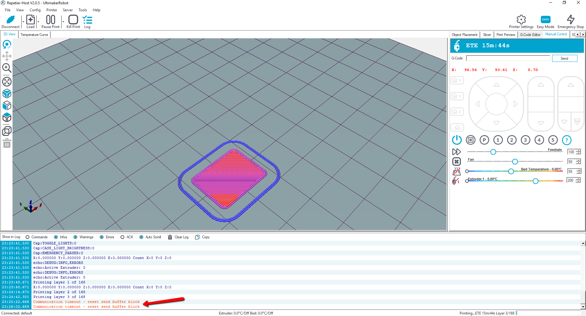
KirAsh4
on 2 Sep 2017
@KirAsh4 There have been some discussion about the board freezing during sdcard access, due to the watchdog expiring. So far only some people have noticed it and only on boot up, but just for testing, if you can increase the watchdog time out up to 8 seconds and run again, it may help to see if something is just taking a bit too long.
victorpv
on 2 Sep 2017
@SmallSharky Chriss Barr wrote a HAL layer for Marlin with the STM32GENERIC arduino core, and I am writing one compatible with Libmaple based cores. Mine is already compiling and the basic stuff works. Still need to enable the watchdog and a few more things, but my time has been spread thing on several things, also testing the Re-Arm.
victorpv
on 2 Sep 2017
@victorpv can i join to this project?
SmallSharky
on 2 Sep 2017
My son pointed out that I have a Prusa i3 that isn't being used for anything so guess what's getting a brain transplant tonight. This will allow me to start working on the X5 GT without disabling either of the printers I'm currently using. Duh...
mperdue
on 3 Sep 2017
@victorpv Made the change but no luck. It still freezes fairly soon after it starts printing, same 'reset send buffer block' message. Furthermore I noticed it's freezing at random spots, it's not specific to when it tries to move Z. Sometimes it freezes mid travel while extruding.
What else should I look at to change and test?
KirAsh4
on 3 Sep 2017
Well it couldn't be easy, where's the fun in that? ;) unfortunately though it could be an issue we all have but haven't triggered, (is the gcode anything special?, not many of the dev team actually have the Re-ARMs (lpc1768) hooked up to printers yet), or specific to the lpc1769 (clocks not being set up correctly perhaps?) this whole branch is still relatively untested with actually printing (even the AVR platform)..
p3p
on 3 Sep 2017
Gcode is a 1" cube. It stops somewhere between the second and third layers ...
KirAsh4
on 3 Sep 2017
Pin 13 is a heart beat (the watchdog reset actually) led, it should be pretty much a steady pulse, is it erratic during the print? ever getting close to the 4 second timeout?
p3p
on 3 Sep 2017
Nope, it's happily flashing away. I did note that occasionally when the print freezes, that LED will come on solid and I have to do a hard reset. But mostly it continues to flash ...
KirAsh4
on 3 Sep 2017
There's no telling if it's flashing at the correct beat though. :)
KirAsh4
on 3 Sep 2017
As long as its steady (same speed as not printing) and pretty fast its more than likely fine, what features do you have enabled?, I haven't tested anything but a pretty default config yet.
p3p
on 3 Sep 2017
That's it, a "default" config. Literally all I did was grab the bugfix-2.0.x branch, set the motherboard to 'BOARD_RAMPS_14_RE_ARM_EFB', set the correct pins for the steppers and extruders in 'pins_RAMPS_RE_ARM.h' and compiled. I can test correct movements on XYZ and E0. The last change I made was increasing the watchdog timer and recompiled.
KirAsh4
on 3 Sep 2017
@Kirash4 I have a mks sbase collecting dust in a shelf, can you post your board and configuration file somewhere? I'll change the minimum, if anything is needed for the sbase, and see if it crashes on me.
victorpv
on 3 Sep 2017
@SmallSharky I need to check my code with the latest 2.0 bugfix branch, then will upload it as a fork. If you have used the original libmaple, or the stm32duino evolution of it, that's what I'm using right now. There is a few small changes that need to be done here and there, which I need to document (some defines clash between the stm32 core and Marlin), but nothing big. I still have to hook up steppers to that and see if it moves, but at least it can communicate and report end stops.
victorpv
on 3 Sep 2017
@victorpv https://github.com/MarlinFirmware/Marlin/compare/bugfix-2.0.x...KirAsh4:bugfix-2.0.x
All you need is the board definition and pins.
KirAsh4
on 3 Sep 2017
@thinkyhead while checking the M100 command in an STM32board I found some issues due to several of the functions in the M100 code using int16_t for memory size. Since the MCU had more than 32KB of RAM, the amount of free RAM was out of range for those functions. I.E:
https://github.com/MarlinFirmware/Marlin/blob/bugfix-2.0.x/Marlin/M100_Free_Mem_Chk.cpp#L210
Changing them to uint32_t seems the best solution and worked on my test, but should I use a different type so in AVRs result in uint16_t and in ARM in uint32_t?
I can edit and submit the PR after testing again.
victorpv
on 4 Sep 2017
M100 should be changed to uint data types.
Changing them to uint32_t seems the best solution and worked on my test, but should I use a different type so in AVRs result in uint16_t and in ARM in uint32_t?
uint32_t is excessive for the AVR's. But M100 is only compiled into the code for debug situations. My vote would be use the same data types everywhere (ARM and AVR) so we can avoid any conditional compilations with #if commands. Having just one version of the code that works everywhere does have some value.
Roxy-3D
on 4 Sep 2017
I have posted the refactored hierarchical Marlin 2.0 branch for examination, discussion, patching, and testing.
The branch makes no changes to code logic, and mainly attempts to produce a clean layout that will be easier to manage and edit, while also giving a basis for even further organizational improvement, as befits a codebase that wants to serve a wide variety of platforms.
Nothing is written in stone concerning the file organization or methodology. G-code categories are fuzzy, but I have tried to make reasonable choices how to group the G-code files. The use of ".h" files for the G-code handlers is designed to be non-disruptive, keeping handlers in the scope of Marlin.cpp.
Parts of Marlin.cpp may be broken out into new compilation units, as demonstrated by tmc2130.cpp/tmc2130.h in the last commit. The movement and kinematics functions are good candidates to start with, and may be grouped into singleton classes to better encapsulate the cartesian position and its conventions as high-level units of the firmware.
thinkyhead
on 4 Sep 2017
So I think I'm hearing a request to try the branch and see if does things correctly?
This is posted in the main 32-Bit branch, but does it make sense to first make sure the AVR's work?
Roxy-3D
on 4 Sep 2017
@victorpv, for memory size recommended to use size_t type for compability with different platforms.
SmallSharky
on 4 Sep 2017
@thinkyhead Thank you for giving TMC features their own little corner. However I'd like to suggest a broader name as the features and commands will be used by TMC2208 and TMC5130 (TRAMS) as well. Maybe src/gcode/feature/trinamic_tmc/ or just src/gcode/feature/trinamic/.
teemuatlut
on 4 Sep 2017
@thinkyhead Compiling for LPC1768 using the bugfix-2.0.x-new-layout branch fails with:
cannot open linker script file Marlin/HAL/frameworks/CMSIS/LPC1768/Re-ARM/LPC1768.ld: No such file or directory.
KirAsh4
on 4 Sep 2017
Is the idea that we drop support for Arduino IDE totally and use PlatformIO for all targets?
 bobc
on 4 Sep 2017
bobc
on 4 Sep 2017
@thinkyhead Compiling for RADDS/DUE using the bugfix-2.0.x-new-layout branch fails with:
C:\Marlin\src\Marlin\Marlin.ino:31:30: fatal error: inc/MarlinConfig.h: No such file or directory
 #include "inc/MarlinConfig.h"
compilation terminated.
exit status 1
Error compiling for board Arduino Due (Programming Port).
Using Arduino 1.8.2 windows 10.
bruce356
on 4 Sep 2017
C:\Marlin\src\Marlin\Marlin.ino:31:30: fatal error: inc/MarlinConfig.h: No such file or directory
Before getting that far, I get a popup from Arduino IDE:
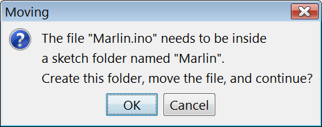
Did you get that popup then press OK? That would mean that the paths change.
bobc
on 4 Sep 2017
@p3p
Chris - I'm back playing with the U8glib again. I've run into a problem that I hope you can point me in the right direction.
In HAL_LPC1768\HAL.h the line #include <algorithm> is causing a "name not found" error. As best I can tell it's because U8GLIB is mostly "C" while <algorithm> is only available in a C++ environment. I see where you can pull "C" libraries into C++ but haven't seen the reverse.
Curiosity questions ...
Is there a reason why the descendants of U8g are still "C" rather than completely C++ (besides historical)?
I see there is an ARM option in U8g2. Is that something you're considering for the long run?
Bob-the-Kuhn
on 4 Sep 2017
You can't use c++ headers in *.c source files.. if that was the question, you would need to use preprocessor (#ifndef __cplusplus) to exclude non c conformant parts (can get messy) though I'm not sure of the context in which you are having the problem with HAL.h.
I presume some developers still aim for the C99 standard compliance to make sure the code is compatible with all the proprietary embedded compilers in the world, but could be wrong, C++ compilers are now just as good for embedded development (in my opinion), but people still tend to overuse classes and inheritance where other paradigm would better suit the situation just because it supports OO.
I think @thinkyhead mentioned looking into moving Marlin to U8g2 at some point somewhere but I could be wrong, its probably the best path. My U8glib-ARM library is just the official ARM version of U8glib with the Arduino versions API added on top to make integrating with Marlin easy with no (other) external dependencies.
p3p
on 4 Sep 2017
@thinkyhead I created a PR that fixes build issues for LPC1768 and allows Arduino IDE to build the platforms it supports, https://github.com/p3p/Marlin/tree/pr_bf2_new_layout_buildfix
I like the table of supported platforms you have added to the Readme but you seem to misunderstand that the LPC1768 HAL doesn't just support the Re-ARM (although it is what we are testing on) in theory it will support all LPC176(8,9) boards when complete. I'm not sure how the Arduino HALs (DUE, TEENSY2) work but in general a HAL platform adds support for an MCU not a single board.
p3p
on 4 Sep 2017
in general a HAL platform adds support for an MCU not a single board
As such, wouldn't it them make sense to rename the Re-ARM PlatformIO environment to something like LPC176x?
I've spent some time yesterday and today trying to clean up all of the compiler warnings that are generated. They're are a bunch of false positive variable may be used uninitialized warnings that I'm wading through to determine the best way to resolve. There are some issues in the LC1768 framework and the U8glib-ARM code. Are we wanting to leave those alone, or can changes be made?
tcm0116
on 4 Sep 2017
@thinkyhead splitting up Marlin_main.cpp into lots of .h files seems rather unconventional. It also seems like it could likely induce multiply-defined variables if someone needs to include one of those files in order to add a new feature.
A more conventional approach would be to have each "module" have a .cpp and .h file, which would allow for local variables and exporting of "public" methods. This starts to lend itself to moving to more of an OO approach.
tcm0116
on 4 Sep 2017
wouldn't it them make sense to rename the Re-ARM PlatformIO
Maybe, but LPC176x is a bit broad, there are MCUs in that category that aren't supported, I know the lpc1769 is binary compatible with the 1768 so its (theoretically)supported by default. There may also be reason to have board specific defines depending on what other hardware features a board has, so I chose to have a PlatformIO environment per supported (well at least tested) board. My intention was to get at least one board working and then worry about the cleaning up and genericifying. There is currently an IS_REARM define that pulls in the pinmap and a few other things but that is not really required anymore since we moved away from trying to transparently support the normal RAMPS pins file in favour of a specific rearm one.
I've spent some time yesterday and today trying to clean up all of the compiler warnings
I have the warning set pretty strict but cleaning them up is always nice, the CMSIS driver in the framework is LPCs code but the rest can be cleaned up if you want to, I'm currently working on the usb stack and MSD, so I'd prefer you didn't change that much ;)
p3p
on 4 Sep 2017
I've spent some time yesterday and today trying to clean up all of the compiler warnings that are generated.
Good! Thank You!
splitting up Marlin_main.cpp into lots of .h files seems rather unconventional. It also seems like it could likely induce multiply-defined variables if someone needs to include one of those files in order to add a new feature.
Marlin_main.cpp has grown to over 13,500 lines of code. It needs to be cut up into smaller modules. And doing it by GCode category type makes some sense. Really... it would make sense to just have initialization and command processing in there.
BUT WE SHOULD NOT HAVE .h FILES THAT GENERATE CODE!!!!!
WE ALREADY HAVE CODE GENERATING .h FILES IN ultralcd.cpp. IT IS AN ABORTION. WE DON"T WANT THAT EVERYWHERE IN THE CODE BASE. If this is just a quick way to do surgery and cut things apart, that is fine. This can _NOT_ be the way we leave the code.
Roxy-3D
on 4 Sep 2017
This can NOT be the way we leave the code.
This is an initial way to break up the code. I felt that it was important to take this step first to retain the more-or-less exact ordering in Marlin.cpp and the same linker behavior as a transitional step before going any further.
The next step would be to rename all those .h files to .cpp files, bring the wrapper conditions into them from Marlin.cpp, and give them all accompanying headers with their public functions. If you want me to go forward with that, I have nothing but time….
thinkyhead
on 4 Sep 2017
I like the table of supported platforms you have added to the Readme but you seem to misunderstand that the LPC1768 HAL doesn't just support the Re-ARM (although it is what we are testing on) in theory it will support all LPC176(8,9) boards when complete.
The table misunderstands this, even if I don't. I want to keep adding to the README, but I don't have an exhaustive list. This is in a very incomplete state, I admit. I am trying to get attention on this new branch so that we can transition before pushing forward with further HAL work. The README will be completed by the time the branch is ready to be published.
thinkyhead
on 4 Sep 2017
splitting up Marlin_main.cpp into lots of .h files seems rather unconventional.
I agree. But it is a necessary (I feel) transitional step to keep them in the same compilation unit that they are in now. It should be obvious that in order to move all these g-code handler files to .cpp will require a lot more molesting of the codebase and a couple more days of labor, due to the need to expose more of the globals in Marlin.cpp to the rest of the codebase… moving many of them over to the headers where they are more relevant. This is meticulous work which I am just starting.
At this point what I mainly want to know is, does the source build? Where are the bugs I need to patch at this step? What is the build size with different configurations? I want to collect this kind of information as a baseline to compare with what we get if we then use .cpp files with external linkage in their place. The compiler can do tricks to optimize the code even when spread across more compilation units. We want to know how this impacts build size, linker behavior, and ultimately, firmware performance.
thinkyhead
on 4 Sep 2017
With the modifications (and re-addition of a missing file) from my branch above everything appears to be building well in the LPC1768 platform.
p3p
on 4 Sep 2017
I see there is an ARM option in U8g2. Is that something you're considering for the long run?
@thinkyhead mentioned looking into moving Marlin to U8g2 at some point
I did indeed! It seems like we would need to continue to support u8glib 1 for AVR going forward because of the behaviors we currently rely on. But it makes sense to focus on u8glib2 for the 32-bit platforms, since performance is no longer a bottleneck. Maybe it can be done with a few macros and low-level functions that each HAL implements, so we can retain all the high-level LCD menu code. Or, maybe it will require, in the long run, re-writing more of the LCD routines for the 32-bit HALs. The "readiness" of u8glib2 and how easy it is to transition is best assessed by @olikraus.
In any case, as @Roxy-3D points out, and as I definitely have on the brain, the LCD code needs a refactoring anyway. The use of ".h" files to insert code into .cpp files is unnecessary, and the LCD code would be well-served by encapsulation in a singleton as the other parts have received. The fragility of the LCD code has been the main thing stopping a major overhaul, but it deserves to be a project of its own.
thinkyhead
on 4 Sep 2017
This can NOT be the way we leave the code.
This is an initial way to break up the code. I felt that it was important to take this step first to retain the more-or-less exact ordering in Marlin.cpp and the same linker behavior as a transitional step before going any further.
The next step would be to rename all those .h files to .cpp files, bring the wrapper conditions into them from Marlin.cpp, and give them all accompanying headers with their public functions. If you want me to go forward with that, I have nothing but time….
splitting up Marlin_main.cpp into lots of .h files seems rather unconventional.
I agree. But it is a necessary (I feel) transitional step to keep them in the same compilation unit that they are in now. It should be obvious that in order to move all these g-code handler files to .cpp will require a lot more molesting of the codebase and a couple more days of labor, due to the need to expose more of the globals in Marlin.cpp to the rest of the codebase…
OK! Good. And if I may make a suggestion... It doesn't even have to be done that fast. I would like to suggest that once the file and folder layout 'works', we add an extra rule. No Pull Requests get merged unless the code they alter is correctly typed as a .cpp or .h file. That way, we don't need to take on the whole burden at once. And various developers can 'share the burden' to some degree.
I'll start with something simple like M48 and see how far I can get.
Roxy-3D
on 5 Sep 2017
@p3p
With the modifications (and re-addition of a missing file) from my branch above everything appears to be building well in the LPC1768 platform.
I think that moving the files also needs the paths changing for Arduino IDE so they are referenced from top level directory,eg. #include "module/planner.h" needs to be #include "src/module/planner.h" etc
bobc
on 5 Sep 2017
I wouldn't usually do that, include paths are relative to the source file?
p3p
on 5 Sep 2017
Is the idea that we drop support for Arduino IDE totally and use PlatformIO for all targets?
@bobc
It should support both. Please advise changes that would be needed.
As for PlatformIO, I can't get it to build with platformio via Deviot in Sublime Text 3 currently. No obvious error thrown, but will check the debug console. I've had to patch Deviot before, so it might not be platformio issue per se.
This is the time to make all decisions how Marlin 2.0 should be organized and packaged, and much developer feedback is needed, especially in the areas of specialty.
thinkyhead
on 5 Sep 2017
It should support both. Please advise changes that would be needed.
My PR above fixes it the only way I know how, by reverting to having a Marlin folder with src folder and Marlin.ino in that folder, the frameworks folder also has to be outside the src folder so Arduino IDE ignores it.
p3p
on 5 Sep 2017
@p3p
I wouldn't usually do that, include paths are relative to the source file?
Oh my bad, I'm still catching up! Your pr_bf2_new_layout_buildfix branch builds great with Arduino 1.8.3 👍
(for Due target.. and also Mega2560).
bobc
on 5 Sep 2017
As for PlatformIO, I can't get it to build with platformio via Deviot in Sublime Text 3 currently. No obvious error thrown
I've confirmed it builds with Atom PlatformIO, but Deviot may be stricter at interpreting the config.
This is the time to make all decisions how Marlin 2.0 should be organized and packaged
I noticed that when you open the project in Arduino IDE now it doesn't preopen any files, would it be better to have configuration(_adv).h in the Marlin folder so they are opened automatically like they used to be? It may help people as there is no obvious way of opening them (I may be mistaken I never use the IDE)
p3p
on 5 Sep 2017
@p3p What's the relevance of the file CMSIS/LPC1768/Re-ARM/startup_LPC17xx.S? I don't want to throw away its changes if it's important. Maybe .gitignore needs to have ".S" added?
thinkyhead
on 5 Sep 2017
CMSIS/LPC1768/Re-ARM/startup_LPC17xx.S is a very important startup asm file, don't be throwing it away again ;)
p3p
on 5 Sep 2017
when you open the project in Arduino IDE now it doesn't preopen any files
@p3p The Arduino IDE shows tabs for every source file in the same folder as the .ino file. It's just a side-effect that it showed the config files in previous versions of Marlin. Config files probably won't be moved back to the root folder at this point.
thinkyhead
on 5 Sep 2017
okay np, I'm just worried about the average user opening up Arduino IDE to make a config change and getting a bit lost.
https://github.com/MarlinFirmware/Marlin/blob/bugfix-2.0.x-new-layout/.gitignore#L41
Now I understand where the asm file keeps going, you're on windows with case insensitive filenames, we need it back again
p3p
on 5 Sep 2017
CMSIS/LPC1768/Re-ARM/startup_LPC17xx.Sis a very important startup asm file, don't be throwing it away again ;)
Tell the world, .gitignore "*.s" rule is problematic. Local settings need to be…
git config core.ignorecase false
out of curiosity why are *.s (asm files) in the gitignore?
p3p
on 5 Sep 2017
I've brought the hierarchical Marlin 2.0 branch up to date with patches from @p3p. It now builds fine within Deviot / PlatformIO for me with the default config. Just waiting to see how Travis likes it.
thinkyhead
on 5 Sep 2017
out of curiosity why are *.s (asm files) in the gitignore?
Some IDE or tool or compilation flag may be leaving droppings for someone. The rule can be removed if it doesn't affect anyone.
thinkyhead
on 5 Sep 2017
There may also be reason to have board specific defines depending on what other hardware features a board has, so I chose to have a PlatformIO environment per supported (well at least tested) board.
That could get out of hand pretty fast as there are already a number of boards that use the LPC1768. Perhaps a better approach is to start work a generic LPC1768/9 environment and add board-specific environments as necessary. This appears to have been what was already done with the 8-bit systems.
It should be obvious that in order to move all these g-code handler files to .cpp will require a lot more molesting of the codebase
Completely. What you've done is an excellent start. I just wanted to make sure we are planning on taking out over the goal line.
However, as I was thinking about it some more, I realized that moving each function into an individual .cpp file has the downside of preventing the compiler from inlining functions. It looks like GCC has Link Time Code Generation (LTCG), which can inline functions at the linker level, but I'm not sure if that's supported by the 8-bit linker.
tcm0116
on 5 Sep 2017
However, as I was thinking about it some more, I realized that moving each function into an individual .cpp file has the downside of preventing the compiler from inlining functions.
Not true! Here are some examples from least_squares.h. We just declare them in the .h file and then use them in the .cpp file.
  /**
   * @brief Formats the duration as years
   * @return The number of years
   */
  inline uint8_t year() const {
    return this->day() / 365;
  }

  /**
   * @brief Formats the duration as days
   * @return The number of days
   */
  inline uint16_t day() const {
    return this->hour() / 24;
  }

  /**
   * @brief Formats the duration as hours
   * @return The number of hours
   */
  inline uint32_t hour() const {
    return this->minute() / 60;
  }
@tcm0116 The optimizing features of the compiler are the only reason for having all those gcode headers unusually included via ".h" files. It's unconventional, but it does produce the smallest and fastest binary in the most compatible manner.
I'm currently refactoring some of the g-code .h files into .cpp files to see how they impact build size and the localization of globals currently bound to Marlin.cpp.
thinkyhead
on 5 Sep 2017
@Roxy-3D right, but I'm referring to functions that are implemented within a .cpp file. All of the functions marked inline in Marlin_main.cpp that are now in .h files can still be inlined by the compiler. However, if you only put a prototype in the .h and move the implementation to a .cpp, then the compiler cannot inline that function.
tcm0116
on 5 Sep 2017
Not true! Here are some examples from least_squares.h:
You're comparing apples to oranges. Class inline methods may be inlined because they are defined in a shared header. If all g-code handlers are moved to .cpp files and not encapsulated into a big class with inline methods defined in their .h files, then they won't be inlined. In order for the compiler to inline functions from separate compilation units, it has to use an option that treats it all as one big source file. I forget the name, but such an option does exist, and can possibly reduce sizes. However, under normal compilation, functions defined in separate .cpp files are linked static and have no possibility to be inlined.
thinkyhead
on 5 Sep 2017
The avr gcc compiler does support link time optimisation (-flto flag) wonder if the Arduino IDE uses it?
p3p
on 5 Sep 2017
However, if you only put a prototype in the .h and move the implementation to a .cpp, then the compiler cannot inline that function.
Yeah. But opinions are going to vary on this. I actually think that is a very good thing. The compiler caused some very difficult to find and debug data corruption issues because it was inlining stuff in G29 and was doing it in a very sloppy and lazy way.
gcode_G29() had a number of support functions that used a fair amount of local variable space. None of them were crazy. But GCC decided to inline every support function and just kept adding to the space allocated on the stack for gcode_G29(). I don't want the compiler playing games if it can't do it in a smart way.
Roxy-3D
on 5 Sep 2017
it has to use an option that treats it all as one big source file. I forget the name, but such an option does exist…
…link time optimisation…
I refer to the -fwhole-program flag, which is kind of sketchy.
thinkyhead
on 5 Sep 2017
I refer to the -fwhole-program flag, which is kind of sketchy.
lto can also be .. unpredictable as it defers most optimisation until the linker to enable cross compile unit inlining ect
p3p
on 5 Sep 2017
The Arduino IDE does use lto with AVR GCC, I haven't seen whole-program used.
bobc
on 5 Sep 2017
@KirAsh4 I created a new board file similar to your Re-ARM, compared the pins with MKS SBASE and they are the same, so I compiled and uploaded to my mks board. Nothing connected to it, so I had to fake the thermistors with 998 and 999. First I set them the other way around, and was simulating 205 degrees for the Bed, and 60 for the extruder, and interesting enough that was causing the board to loop in some temperature code and not even respond to the USB serial commands. Corrected that, and run a test print with watchdog disabled (had disabled it when trying to find why it was acting up), and completed fine in 23 minutes. I have re-enabled the watchdog and running the same print (with pronterface btw), and will see how it goes.
This is using the 2.0 branch without the folder reorganization, and my steppers step/mm settings.
victorpv
on 5 Sep 2017
@victorpv So you're using bugfix-2.0.x then, not the -new-layout one? I skipped dealing with thermistors by issuing a 'M302 P1' command to allow cold extrusion. I'll refresh my pull and recompile in case anything changed.
KirAsh4
on 5 Sep 2017
@victorpv If you have access to the ftdi serial port (Serial Port 0) you will get more information about how far the boot gets and possibly what went wrong, usb serial often wont even try to connect until after the firmware gets stuck or watchdog resets for some reason. Then again it might not output anything which would mean it fails even before the SystemInit completes.
p3p
on 5 Sep 2017
@p3p I realized the mks has the SWD pins available, so I am using that :) I got to see where it was getting stuck when my fake temps were wrong. It did surprise me that the serial USB would not be responsive at all, but after correcting the fake temps it runs fine. I ran a second print with pronterface with watchdog at 4s, and still not having problems with the print.
But the boot problem with sdcards and Windows is still happening some times, in fact worse than with the re-arm board, so I'm now trying to see how far it gets with different cards. It seems like the watchdog is expiring somewhere between the end of setup() and the beginning of loop(), but I need to try a couple different cards to see how far it goes with each.
@KirAsh4 Right, not the new-layout one. I haven't tried with M302 P1, but can will try it after I spend some time checking the boot with different cards. Btw a second print with watchdog enabled also completed fine in 22 minutes.
victorpv
on 5 Sep 2017
@victorpv No such luck for me. Tried both the bugfix-2.0.x branch as well as the -new-layout branch. Both of them will stop shortly after it starts printing with communication errors. No idea how to debug this.
KirAsh4
on 5 Sep 2017
@mperdue did you get your x5 working? I ordered the x5 mini, but really don't want to have to use smoothieware to use it. Does the 2.0 branch support ethernet ability like smoothieware? I am done printing over USB.
klcjr89
on 5 Sep 2017
@klcjr89 Not yet - life keeps interfering with my plans. I've created an index that I hope is a reasonable starting point for the pins file. I plan (again) to connect the board to an unused Prusa i3 today if the world will leave me alone for awhile.
mperdue
on 5 Sep 2017
@klcjr89 in my opinion (probably not the official Marlin position) using the extra performance we have to run a web server on a realtime critical system is not the best idea (for many reasons) even if we have enough power to do it (badly), I may add support to send gcode over telnet at some point but its not a priority. (also we need the Ethernet pins for other things in order to fully support RAMPS on Re-ARM) The real solution to the needing a printer hooked up to USB is a RaspberryPI (or similar) so you can have a responsive web interface and not interfere with the critical timing of controlling a printer.
p3p
on 5 Sep 2017
I have loads of issues with usb and octoprint, but I suspect that's due to me upgrading to leadscrews for all axes and just the fault of the 8 bit AVR and 40Khz stepping and has nothing to do with usb (although I also run a 720p usb webcam) so I can't wait to dump usb. I can barely get usable prints. 1/16th microstepping and my steps per mm are: Z and E are 0.9º steppers.
DEFAULT_AXIS_STEPS_PER_UNIT { 400, 400, 800, 180 }
klcjr89
on 5 Sep 2017
@klcjr89 have you tried turning down the bad rate setting in Marlin to 115200?
tcm0116
on 5 Sep 2017
My baud is actually set to 115200; I found that the recommended higher setting for the MKS Gen-L had all kinds of trouble.
klcjr89
on 5 Sep 2017
Another thing to consider is that the RPi has USB bandwidth issues. If
you're running a USB webcam at high resolution, that can cause issues. You
could try disconnecting the webcam just to see if that makes a difference.
tcm0116
on 5 Sep 2017
Yes, I think that is another thing contributing to the print quality. I have tested with the webcam unplugged, and it seems to make a difference, then I plug it in again to make the same print and it'll be fine, but randomly on another print the issues come back, so it's so random and not consistent. Webcam is 720p 30fps.
The issues aren't consistent is why I haven't completely removed the webcam yet, plus I need to monitor the prints too.
Can someone tell me how fast I can actually go with 40Khz 8 bit AVR with my above steps_per_unit? Been trying to figure out what I can really do all week.
To clarify: all axes leadscrews are 8mm lead four start. X and Y motors are 1.8º step angle. Z and E are 0.9º step angle (E is bowden direct extruder, no gearing).
DEFAULT_AXIS_STEPS_PER_UNIT { 400, 400, 800, 180 }
Thanks for the help!
klcjr89
on 5 Sep 2017
Who would've thought.. so I've always preferred using ethernet instead of WiFi, but just learned that the ethernet on the raspi is on the same bus as the USB, so I have just enabled WiFi and unplugged the ethernet cable to see if that also helps. Also reduced frame rate from 30 to 15.
klcjr89
on 5 Sep 2017
@klcjr89 Have you seen this? https://github.com/luc-github/ESP3D
That leaves the web side work offloaded to a different MCU. I have an ESP8266 programmed with it, but haven't tested yet, but I think it's a good solution for wifi printing while leaving the printer board in charge of just printing.
@KirAsh4 did you try disabling the watchdog altogether?
@p3p About the boot issues with some sdcards, I tested with 3 cards yesterday night with the debugger plugged. When it reboots I can't even see the stack trace, so I have to just place watchdogs at different points to see how far before is resets. With the 16GB card it crashes during setup(), right before or after the call to read the eeprom. With the other 2 cards it crashes a bit later, about the end of setup() and starting loop(). From what I see in the code, the first watchdog reset is called during loop, while initializing the normal sd card (sdfat library part).
I inserted a watchdog reset in setup() before reading the eeprom, but still it would crash before reaching that line many times, even thought it was not far from the watchdog being initialized.
I think either the watchdog should have a longer period, or we need some watchdog resets in the code that manages the microsd. Looks to me like under the right conditions of sdcard, OS, sdcard content or format, etc, that code takes longer than 4s to return back to main program.
If there is anything you want me to test or check with the debugger let me know. I bumped the watchdog to 8s for testing and I don't remember having any crash while it was like that.
victorpv
on 5 Sep 2017
The OctoPrint web UI is much smoother now since switching to WiFi and unplugging ethernet. If anyone can help me figure out how fast I can go with my current 8 bit MKS board that would be much appreciated.
klcjr89
on 5 Sep 2017
@klcjr89 if I understand right you are asking how fast in mm/s you can go per axis at 40Khz with your steps/mm above? if so, is just a matter of dividing. You can do 40000 pulses per second, and need 400 per mm, so 40000/ 400 = 100mm/s. You can calculate the same for the other axis. If I didn't understand your question correctly let me know.
victorpv
on 5 Sep 2017
@victorpv what I don't understand is, what about multi axis moves such as X and Y at the same time. If both were hyptothetically set to 100mm/s wouldn't that be over the 40Khz limitation? Thanks!
klcjr89
on 5 Sep 2017
No... The limits are set and controlled on a per axis basis. No axis will be allowed to go past its specified limit.
Roxy-3D
on 5 Sep 2017
How is it that if two axes (such as X and Y) simultaneously go at 100mm/s not go above 40kHz if the steps per mm are 400? Is it really 40kHz per axis or not because I can't seem to think it through
klcjr89
on 6 Sep 2017
Yes... The total movement when all axis are added together is more. But the limits are managed on a per axis basis.
Roxy-3D
on 6 Sep 2017
Ok so maybe I bought the 32 bit board for no reason then :( I have alot of other stuff enabled such as 225 point mesh, BLTouch and advanced pause feature so maybe all of the above is choking the atmega.
klcjr89
on 6 Sep 2017
Graphical LCD Displays are probably the single biggest CPU cycle hit. Just switching to 20x4 helps a lot.
Roxy-3D
on 6 Sep 2017
Edit: I see that 20x4 would mean a physial hardware change. Would love to disable the LCD but I have mesh and advanced pause features enabled and I can't compile without it being enabled. @Roxy-3D Sorry to sidetrack thread!
klcjr89
on 6 Sep 2017
I don't know. But a lot of boards support either.
Roxy-3D
on 6 Sep 2017
Hmm, disabled my graphic lcd and I can still compile even with UBL enabled; that must be a recent change.
klcjr89
on 6 Sep 2017
@klcjr89 the 20x4 and graphical LCDs are completely different, so you'd
have to get a new controller.
tcm0116
on 6 Sep 2017
I am going to disable advanced pause feature and try another print without LCD enabled this time. Does anyone know if Z hop for firmware retraction was fixed when you have UBL enabled?
klcjr89
on 6 Sep 2017
A quick update on the -new-layout branch….
The initial breakup of all G-codes into .h files was a good first step, as the main thing was to produce a new layout that could compile but without making any functional change to the firmware. Regarding the breakup of g-codes, that first stage was definitely just a cosmetic change, but is proving useful to go forward.
I'm taking inspiration from @Roxy-3D reminding me that we don't have to lose inline just because we move things into .cpp files, so long as all such code is encapsulated into static singletons, and only the smaller inline-able methods need to be defined in the .h files for the new singletons.
So, the question then becomes, how best to package the G-code handlers into singletons? And the answer is, by a relatively tedious process of continuing down this same road. I will take each G-code handler now inside an .h file and go through a quick refactor…
- Rename the
.hto.cppfile and compile to see where it fails, citing dependencies. - Bring in the needed
externand#includelines to resolve the dependencies. - In some cases shift the definition to the g-code handler files, or added headers.
By doing this in groups of g-codes that all relate to the same config option, they can then be grouped into a singleton class, any feature-related globals and functions currently defined in Marlin.cpp will be moved to the new singleton class. Any functions they share with other config features can be encapsulated in a shared friend class.
As long as most development and bug-fixing focuses on the HAL, I can continue to refine the G-code handling code and structure without disrupting your work. As long as patches made to Marlin_main.cpp and other files are straightforward, they shouldn't be hard to bring into the refactored branch, as the intent is only to reorganize and not, largely, to modify the code.
To make it easier to follow changes, I will re-do the -new-layout branch commits again, except this time I will move all the files, unchanged (except renames), to their new locations, and only afterward apply all the textual changes to the files. That set of textual changes will be primarily to the #include lines, so it should make a nice picture of how dependencies are affected.
thinkyhead
on 6 Sep 2017
Does anyone know if Z hop for firmware retraction was fixed when you have UBL enabled?
Yes. That bug is fixed.
I will take each G-code handler now inside an .h file and go through a quick refactor…
- Rename the .h to .cpp file and compile to see where it fails, citing dependencies.
- Bring in the needed extern and #include lines to resolve the dependencies.
- In some cases shift the definition to the g-code handler files, or added headers.
My guess is there is one more fuzzy bullet point. There are going to be extern's that should be picked up via #include files that don't exist yet as an area is being worked on. The front end of this is going to be harder than the tail end. It might make sense to jump ahead when one of these references is discovered to that area and add an .h file that can declare the required entry. Ultimately... each area will have its own .h file. But until that area is actually 'fixed' it won't have its .h file done.
Saying it another way... In order to untangle the cross references... It might make sense to just plan on there being a .h file for each category. And as references are discovered that are outside of a category, the appropriate .h file can be modified and then included in the category where the actual work is being done.
It's going to be some work to untangle the spider web. I wonder if this is something others can help with. It might be possible for the bulk of each area's .h file to be constructed by helper people.
Roxy-3D
on 6 Sep 2017
we don't have to lose inline just because we move things into .cpp files, so long as all such code is encapsulated into static singletons, and only the smaller inline-able methods need to be defined in the .h files for the new singletons.
Actually... I think the rule the compiler uses is a function body declared in a .h file is just like a big #define. It doesn't have to be associated with a class or be part of a singleton. I think the inline key word tells it not to generate code when it is is first defined... but later if it is used, cut & paste it into the compilation.
I think even .c files can declare inline functions in their .h files without any hiccups.
Roxy-3D
on 6 Sep 2017
Continued at #7622…
thinkyhead
on 6 Sep 2017
I think the rule the compiler uses…
A ".h" file is always included by one or more ".cpp" and/or ".h" files in a project tree, and otherwise the compiler ignores them. When #include is used the compiler just literally interprets the contents of the ".h" file as if it were contiguous with the ".cpp" or ".h" file in which it is included. While a given ".cpp" file will only be compiled once, a ".h" file is compiled anew every time it is #included in a ".cpp" file. In fact, any filename in an "#include" will be compiled as C++. The ".h" extension is just used to get C-style syntax coloring in the text editor.
The inline keyword is a hint to the compiler that it may inline the function or class method, but the compiler decides ultimately whether to inline it in each instance or not. The FORCE_INLINE macro exists to force the compiler to inline something that should be inlined every time.
The compiler may do similar things even with non-inline stuff. A function that takes a float & for example, will be compiled into two distinct functions if it is called once with a variable and then again with a literal float.
thinkyhead
on 6 Sep 2017
Yes. And if the .h file doesn't generate any code, it can be included as many places as needed. The key thing is the .h file can't generate code. And my experience is any function declared as inline doesn't generate code until it is actually used some place.
Roxy-3D
on 6 Sep 2017
First trial with Re-ARM and last bugfix 2.0.x new layout :
- PlatformIO is all but user intuitive (my opinion ;). Needed to uninstal and reinstall a few times because no access to my projects anymore... )
- What works : Already a lot :
- Heater, Bed, fan are working as expected.
- Temperature (bed and nozzle) are reported correctly.
- Motors are running smoothly (no small “stop and go” at high speed as with mega 2650)
- Using the special cable provided with re-arm (separate +5V), LCD is responding.
- Very few modifications in my configuration and configuration_adv files
What is not perfect:
- LCD and SD Card are not friends (as already mentionned by others):
- Introduction of a SD card induces 2 lines crossing the LCD just in the middle and on the last line of the screen. It disappears after a few seconds. This is directly seeable at start. If there is a SD card in the slot (LCD slot) the 2 lines appear at the “marlin” bootscreen.
- The same phenomenon happens when introducing a card at any moment. 2 lines corrupt the screen.
- When looking at the SDcard menu, when circulating in the directory, the move of the 2 bars corrupts also the screen. When corruped, it will stay like that even when coming back and fort to the main screen. It is not refreshed.
The Custom bootscreen option gives a build error (btw how to copy those informations from platformIO? Drag and drop does not work for me (takes the full page in one shot))
- The #define SPEAKER option gives also a build error. But even without this option, the buzzer is working fine.
Next step: reassemble the printer and print an object
 Bergerac56
on 6 Sep 2017
Bergerac56
on 6 Sep 2017
@Bergerac56 what kind of LCD are you using?
tcm0116
on 6 Sep 2017
Using latest "Marlin-bugfix-2.0.x-new-layout.zip" from 3 hrs ago Win10
In file included from sketch\src\gcode\motion\G0_G1.cpp:25:0:

sketch\src\gcode\motion\../feature/fwretract/fwretract.h:30:33: fatal error: ../inc/MarlinConfig.h: No such file or directory

 #include "../inc/MarlinConfig.h"

compilation terminated.

exit status 1
Error compiling for board Arduino/Genuino Mega or Mega 2560.
@tcm0116 I use a RepRapDiscount_Full_Graphic_Smart_Controller
Bergerac56
on 7 Sep 2017
@bruce356 Sorry 'bout that. I'm going to keep a separate branch for my ongoing work, and will shortly restore bugfix-2.0.x-new-layout to a known working state and make sure it is always buildable — or at least passing our Travis testing. Thanks for the heads-up!
thinkyhead
on 7 Sep 2017
Just for testing I am adding functions to read and write the eeprom file from the normal sdcard (to test it with the stm32f1 HAL). I needed to add 2 functions to the Marlin cardreader files, so they can read and write an array from flash using the same file and card objects it uses for opening text files. Now my question is, would this be of value as an option outside any HAL, so we can read and write a configuration file from the normal sd card? if so, it can be done as I was doing (same file object) or I can further modify things so it uses a separate file object (so both the config file and a print model can be opened at the same time). I dont see a use case for opening both at the same time, but I'm new to printing, perhaps users want to change eeprom values while they print from sdcard. Or perhaps there is no much value to adding this at all to all the boards, and I should just keep it behind the HAL.
victorpv
on 7 Sep 2017
would this be of value as an option outside any HAL, so we can read and write a configuration file from the normal sd card?
I like this idea. My only suggestion is that if Marlin is configured to
load the configuration file from the normal SD card, then it should be
expected that the card is installed when Marlin boots. Perhaps the printer
should halt or some sort of error screen should be displayed if the SD card
is not installed, so that the user is keenly aware that their settings have
not been loaded.
tcm0116
on 7 Sep 2017
Has anyone had any luck with BLTouch? I've got the Smart version, which is supposed to work with either 3.3V or 5V. The lights come on, but it doesn't do the self test on boot and I can't get it to respond to commands. It's as if the PWM is not working.
tcm0116
on 7 Sep 2017
It is my belief the BL-Touch does not require any pulse train for it to do the 'self test' at power up.
Roxy-3D
on 7 Sep 2017
@Roxy-3D you might be correct, but I do know that setup() resets the BLTouch and then deploys and retracts it.
tcm0116
on 7 Sep 2017
My apologies... I thought you meant it did not do the built in, power up self test.
It does do that, right?
Roxy-3D
on 7 Sep 2017
Actually, it's not performing the power-on self-test. After looking at the
antclabs site, it looks like I have to cut a trace on the BLTouch to make
it work with the 3.3V supplied by the Re-ARM board. Alternatively, I can
run 5V to the servo connector block on the RAMPS board. I'll look into
those options when I get home this evening.
tcm0116
on 7 Sep 2017
Speaking of EEPROMs and SD cards:
Would EEPROM emulation in flash be of any value?
The downsides would be:
- The flash can only be erased sector-wise, so you would have to commit either a 4k or a 32k sector to it.
- You are only guaranteed 10 000 writes for each flash sector.
 alex-gh
on 7 Sep 2017
alex-gh
on 7 Sep 2017
@alex-gh this was discussed quite a lot when we initially set up the emulation, both directions have merits, HAL Platforms can implement the Persistent Storage api however they see fit as it is behind the HAL, and with a config option we could have both methods available to the lpc1768. The Persistent Storage api hides any implementation differences so whether its a onchip EEPROM, connected by spi/i2c, an sd card, or connects to a webserver it makes no difference to Marlin.
p3p
on 7 Sep 2017
Anyone have any old magnetic-core memory laying around? That'd be fun...
tcm0116
on 7 Sep 2017
@tcm0116 I’ve got a plated wire memory board somewhere around here. It was a Minuteman III throwaway after a system upgrade.
mperdue
on 7 Sep 2017
@p3p the question I had was, whether it would be of value to make the EEPROM emulation on the SDcard available to all platforms, or keep it behind the HAL. Since the LPC1768 already does that (although requiring a second card), and other platforms may use it too, I was thinking that perhaps would be better to make it available to all in a common file.
2 reasons I see to keep it out of each MCU HAL, 1st because if the implementation is common, less to maintain in separate HALs, and more compatibility between them, and 2nd, that emulation is not dependent on the MCU used, it just depends on the SDcard, which is already part of the main code. It does not access the SPI port directly, not even the sdfat directly, but thru the cardreader.h functions.
Technically doesn't matter if the board is started without the card, the card can be inserted at any time and the values read with the M501 code or with the menu options, similar to how you can insert a card and then print a file at any time. I think I will separate this conversation to a new feature request issue to not hijack this thread, since the scope is beyond specific HAL implementation.
victorpv
on 7 Sep 2017
Yes, it could be a generic feature, although the reason I was happy implementing it on the Re-ARM was because it has a very reliable, short, connection to the onboard sd card, its not going to to have communication or connection faults even in a relatively noisy environment and is guaranteed to be present. The usual long unshielded ribbon cable that controllers use is anything but reliable (and completely out of spec for SPI). There are a few places where the line between what should be behind the HAL and what is a Marlin feature is a bit blurred and it will get clearer going forward, in theory only the hardware drivers should be behind the api, the Persistent Storage is a direct replacement for the eeprom functions and as such it was assumed there would be one implementation per HAL Platform, even if it was just a redirection to the framework supplied eeprom functions.
p3p
on 7 Sep 2017
Here's a picture of Marlin 2.0 running on a Re-ARM board in my delta printer. I'm actually running the rebase-bugfix-2.0.x-aug31 branch as the bugfix-2.0.x branch is a little behind and I was having a few issues. Here are a few things I've noticed so far:
- Sometimes the thermistor reading for the hot end drops down 20-30 degrees and the power supply gets a nice workout trying to keep up with the PID. This might be a result of a poor crimp in my cables, so I'll look into that some more.
- Setting a value for Vmin causes the nozzle to move erratically. This might be completely unrelated to the Re-ARM, as I've never set that value before. I forgot to turn off auto cooling in Slic3r, and I'm too impatient to wait for a slow print 😁
- The Smart BLTouch doesn't seem to like running on 3.3V with the Re-ARM. I did cut the trace above the connector to put it in 3.3V mode, but it kept failing when trying to deploy the probe. I soldered the two pads back together and put 5V on the servo power bank, and it's working great.
- Using the Move Axis command in the LCD doesn't appear to use the segmented move operation on the delta machine, so large movements end up being parabolic. Once again, probably not Re-ARM specific.
- I seem to be getting a rather large blob at the beginning of the infill on the fist later. I'm using hardware retraction, so there might be something going on there.
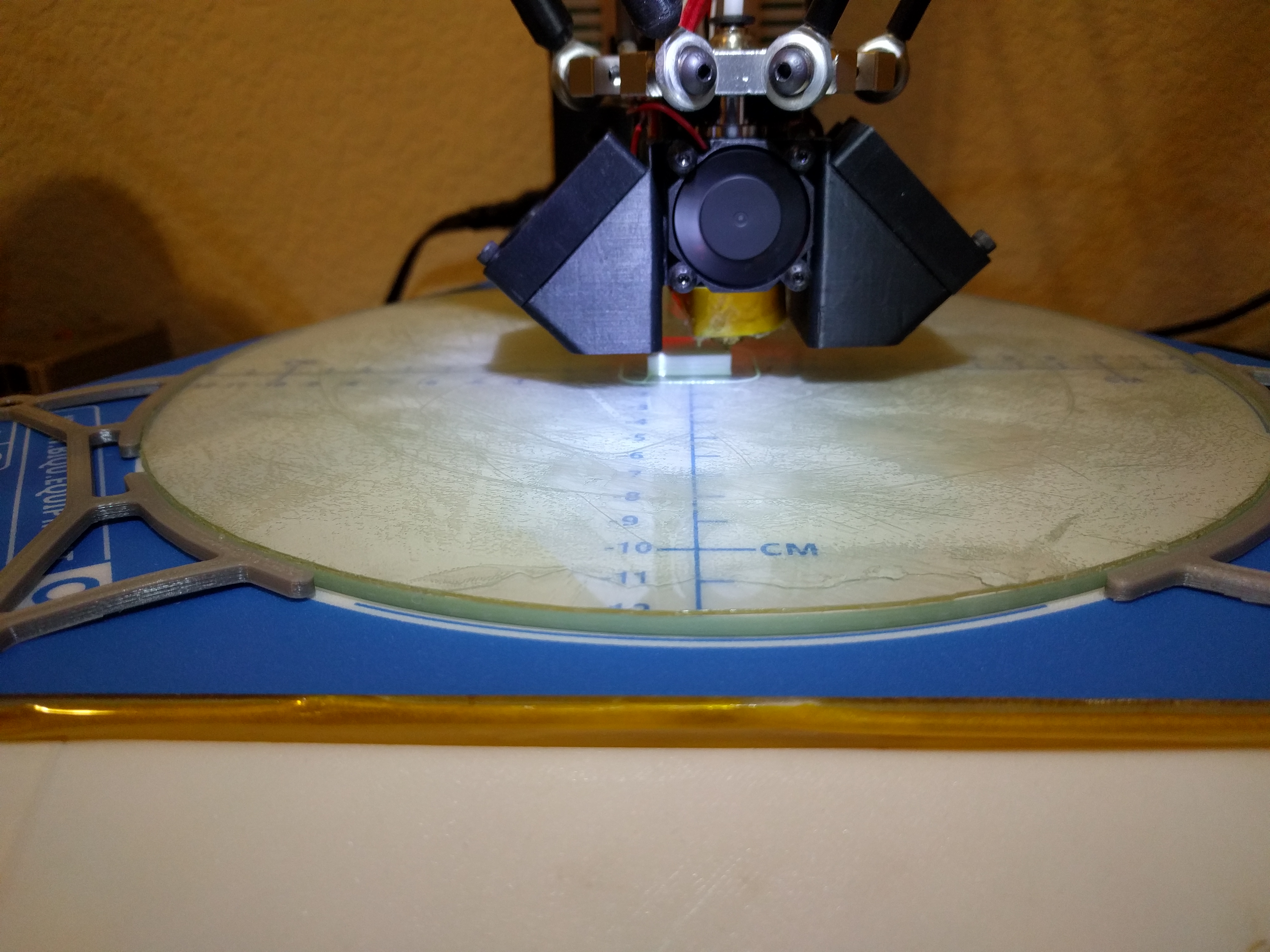
tcm0116
on 8 Sep 2017
@tcm0116 Please let me twist your arm super hard and make you order a http://www.ebay.com/itm/MAX7219-Dot-Matrix-8x8-Led-Display-Module-MCU-Control-For-Arduino-1T4-/292178250967?epid=15002515734&hash=item44072e4cd7:g:rQEAAOSwOtdYTge9
We are going to gain a huge amount of information when we see the LED's while your Delta is printing.... My bet is the stepper queue never gets drained more than 1/2 way on the Re-ARM board. But even if it does... we are going to have the tools to adjust the various parameters.
Delta's (and Scara's) are the big reason to be making changes so Marlin can run on 32-bit processors.
The code is already in place to SEE how well the breaking up of moves into small segments is being handled by a given machine and its electronics. https://github.com/MarlinFirmware/Marlin/blame/bugfix-1.1.x/Marlin/Configuration_adv.h#L1387-L1413
Roxy-3D
on 8 Sep 2017
@Roxy-3D - done. I can already tell you that the CPU load is reduced
because I can use the LCD while it's printing. That was pretty much a
futile effort on the 8-bit processor.
One thing I've noticed about how the moves on a delta are segmented is that
the number of segments for a particular move is based purely on the speed
of the move. This seems odd to me as that would result in a different set
of segments (which would have different lengths) if the same print was done
at a different speed. It seems to me that it would make more sense to have
a fixed segment length and then just limit the number of segments that are
processed in a given period.
By the way, it looks like my thermistor issue was a bad crimp, so that can
be stricken from the record. Also, I didn't get a blob in the first layer
this time, so I'll just have to keep an eye out to see if it happens again.
tcm0116
on 8 Sep 2017
Cube 2 turned it really good. I disabled auto cooling in Slic3r, so it printed pretty quickly and there was no stuttering since Vmin was set to 0. I got a blob on the top layer, but it's possible that I have my retraction speed too high and the extruder missed some steps on the retract. I'll lower the speed and continue monitoring.
Things are looking good. Great job team!
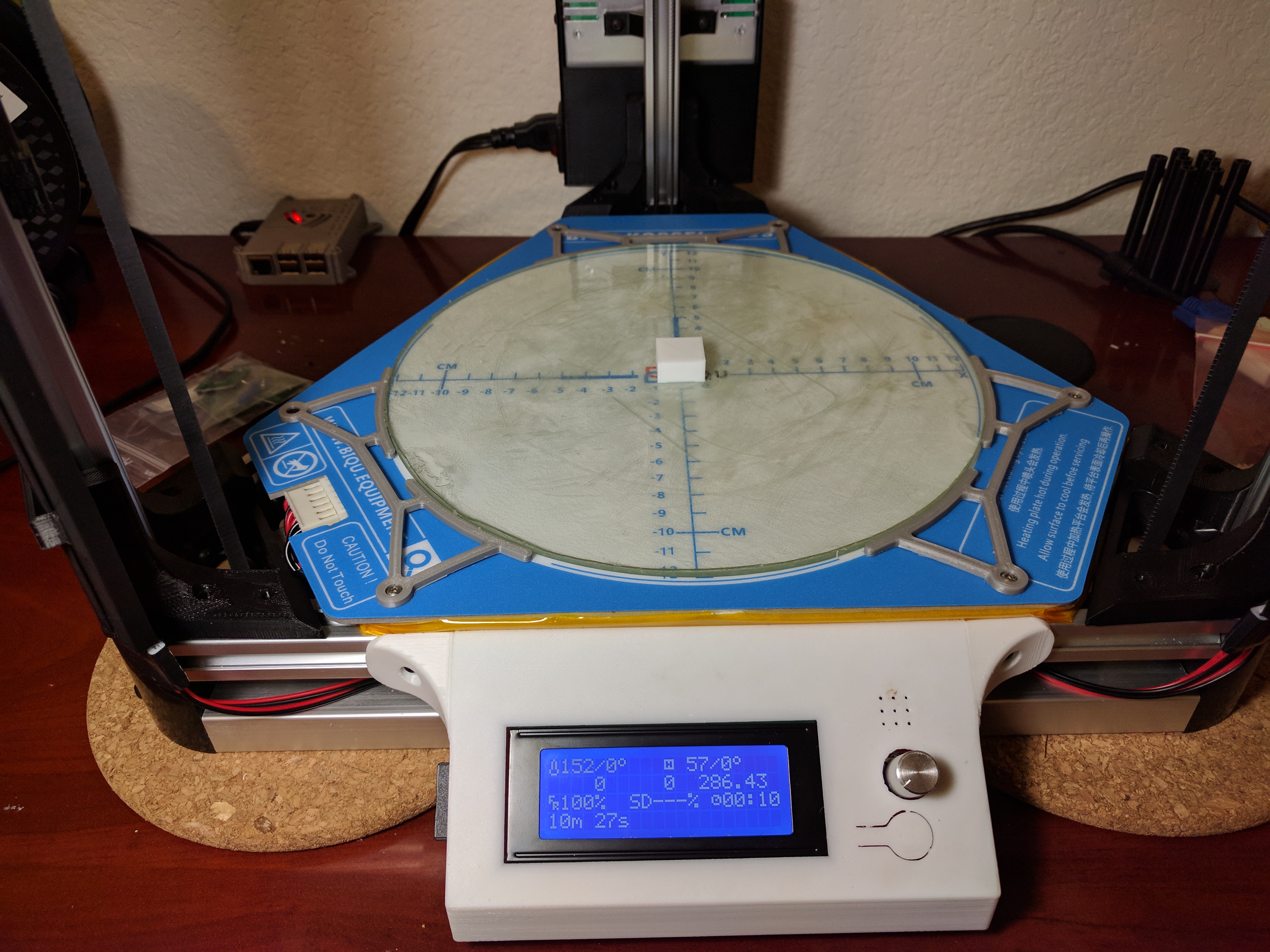
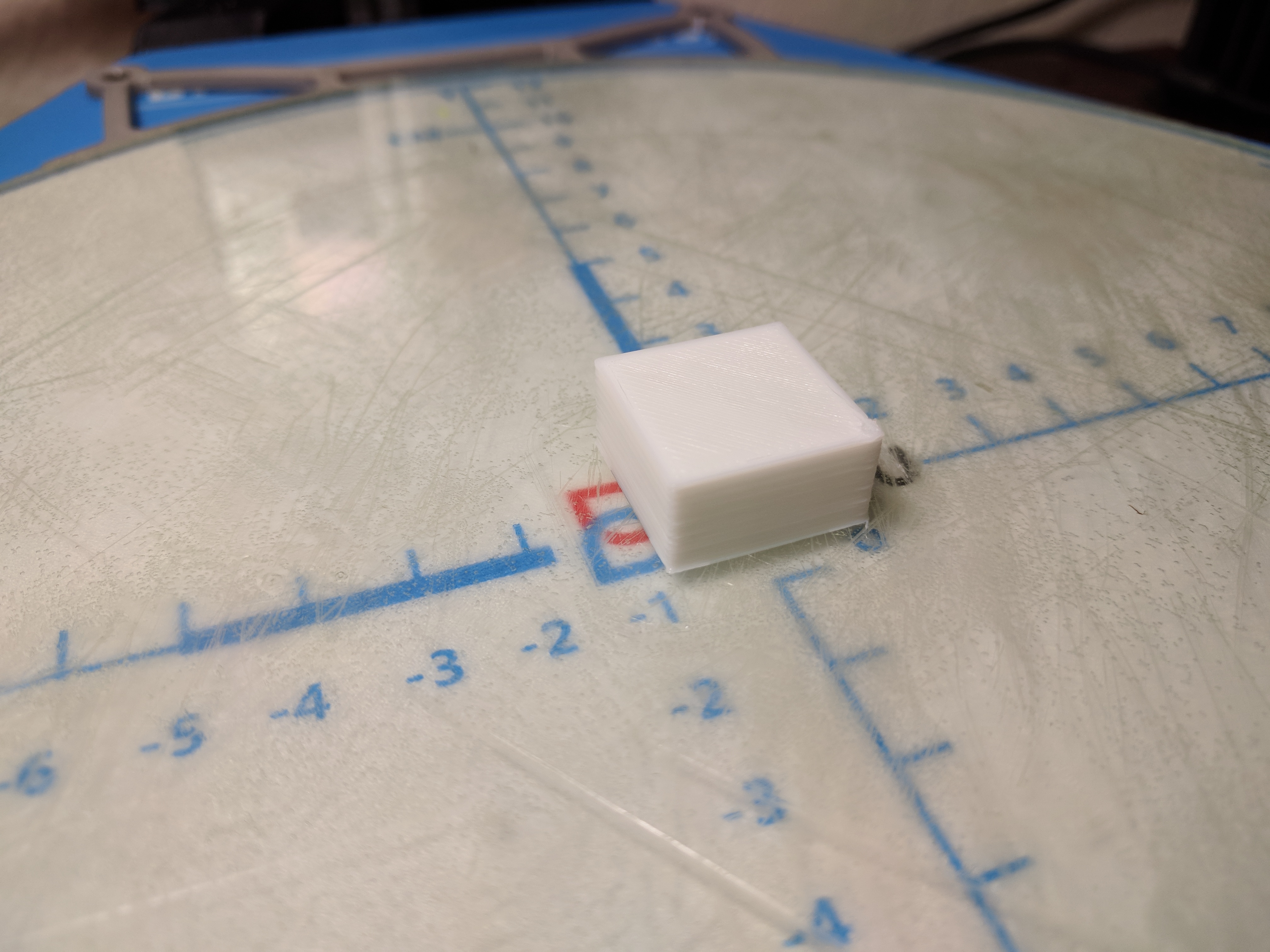
tcm0116
on 8 Sep 2017
Has anyone tried moving the jumper on the Re-ARM to the USB position with it connected to the RAMPS to see if it will stay powered via USB with RAMPS powered off like the 2560? The Re-ARM Quick Start Guide states the following, so I'm not sure if there's any possibility of damaging the Re-ARM if power is applied to the RAMPS with the jumper in the USB position.
Move red jumper to USB on Re-ARM. This allows the board it to get power from USB for testing purposes. Make sure to replace it back to INT before installing to your RAMPS board.
tcm0116
on 8 Sep 2017
My Re-ARM is getting power from the USB bus right now. I have the jumper in that position. And the RAMPS board is split. Most of the RAMPS board is getting +5 V. from the USB connector. But I have a LM7805 regulator that is feeding +5 V. power to the Servo Connector to give the BL-Touch what it needs.
And of course.... The 20x4 LCD panel is getting +5 V. from that same LM7805 regulator....
Roxy-3D
on 8 Sep 2017
Do you have a RAMPS connected and have you put 12V on the RAMPS with the
jumper in the USB position while the Re-ARM is connected to a PC?
tcm0116
on 8 Sep 2017
I can send you some pictures in the morning if you want them... But I have only 12 volts going to the RAMPS board. (Except for the +5 V from the LM7805 going to the servo connector). I do have the jumper in the USB position and it talks just fine to PronterFace on the computer with the 12 volt power supply powering the high current stuff (like the stepper motors and heaters) on the RAMPS board.
All of that is good.
Roxy-3D
on 8 Sep 2017
How would I get BLTOUCH working in this latest Marlin v2 - thanks
Radds/Due board - are there new instructions for BLTOUCH in this release?
In file included from sketch\src/inc/MarlinConfig.h:38:0,

                 from E:\3D printer info\~MTW Create\Arduino DUE-RADDS-GLCD\Marlin v2.0.x bugfix\Marlin 2.0x-Bugfix 07-09-2017_TEST config for Create\Marlin-bugfix-2.0.x-new-layout (1)\Marlin\Marlin.ino:31:

sketch\src/inc/SanityCheck.h:592:8: error: #error "SOLENOID_PROBE requires SOL1_PIN. It can be added to your Configuration.h."

       #error "SOLENOID_PROBE requires SOL1_PIN. It can be added to your Configuration.h."

exit status 1
Error compiling for board Arduino Due (Programming Port).
@tcm0116 glad that's going so well, we still haven't adjusted planner queue size although we have a considerable amount of memory left to throw at the problem if needed, (the entire 16KB Ethernet RAM Block could be reserved for it if we wanted)
Has anyone tried moving the jumper on the Re-ARM to the USB position with it connected to the RAMPS to see if it will stay powered via USB with RAMPS powered off like the 2560?
I use external MOSFETS and stepper drivers so the 24V is never connected to the RAMPS, the main issue with running the Re-ARM off of the USB connector is that the display backlights draws too much current for the 5V regulator (I think), mine is currently powered from the ftdi connector to avoid any rewiring.
Sometimes the thermistor reading for the hot end drops down 20-30 degrees and the power supply gets a nice workout trying to keep up with the PID. This might be a result of a poor crimp in my cables, so I'll look into that some more.
I'm surprised that was a hardware fault its a known issue with the ADCs effecting the PIDs I am going to add some extra filtering, https://github.com/MarlinFirmware/Marlin/issues/7585#issuecomment-326378824
p3p
on 8 Sep 2017
@bruce356 Assuming normal pin connections for a Z switch (e.g., an endstop) and a Servo, you should only need to enable BLTOUCH. Also, make sure to disable SOLENOID_PROBE.
thinkyhead
on 9 Sep 2017
Hi All
Has anyone tried the re-arm with a E3d PT100?
I'm getting a temperature reading, but its about 20 degrees too high at roughly room temperature.
I measured the voltages for 5v and 3.3v. It seems to be good. At the temperature, it was giving the right voltage, but the readings from the ADC are too high.
So instead of reading/returning 264 its returning 279.
Any ideas?
 apballard
on 9 Sep 2017
apballard
on 9 Sep 2017
Hi folks. I have an update on my refactor progress at https://github.com/MarlinFirmware/Marlin/issues/7622#issuecomment-328268849
thinkyhead
on 9 Sep 2017
@thinkyhead, thanks for the reply, with your instruction/help I started from scratch and used the default Configuration.h and default Configuration_adv.h
Only change made to Configuration.h
define MOTHERBOARD BOARD_RADDS
define BLTOUCH
Left at default:-
// #define SOLENOID_PROBE
define Z_MIN_PROBE_USES_Z_MIN_ENDSTOP_PIN
// #define NUM_SERVOS 3
The above fails to compile using Arduino v1.8.2 with following errors:-
sketch\srcMarlin.cpp:439:3: error: 'HAL_SERVO_LIB' does not name a type
HAL_SERVO_LIB servo[NUM_SERVOS];
^
sketch\srcMarlin.cpp: In function 'void servo_init()':
sketch\srcMarlin.cpp:680:5: error: 'servo' was not declared in this scope
servo[0].attach(SERVO0_PIN);
^
sketch\srcMarlin.cpp: In function 'void bltouch_command(int)':
sketch\srcMarlin.cpp:440:28: error: 'servo' was not declared in this scope
#define MOVE_SERVO(I, P) servo[I].move(P)
^
sketch\srcMarlin.cpp:1861:7: note: in expansion of macro 'MOVE_SERVO'
MOVE_SERVO(Z_ENDSTOP_SERVO_NR, angle); // Give the BL-Touch the command and wait
^
sketch\src\gcode/control/M280.h: In function 'void gcode_M280()':
sketch\srcMarlin.cpp:440:28: error: 'servo' was not declared in this scope
#define MOVE_SERVO(I, P) servo[I].move(P)
^
sketch\src\gcode/control/M280.h:31:7: note: in expansion of macro 'MOVE_SERVO'
MOVE_SERVO(servo_index, parser.value_int());
^
In file included from sketch\src\Marlin.h:36:0,
from sketch\srcMarlin.cpp:31:
sketch\src\gcode/control/M280.h:35:31: error: 'servo' was not declared in this scope
SERIAL_ECHOLNPAIR(": ", servo[servo_index].read());
^
sketch\src\core/serial.h:58:76: note: in definition of macro 'SERIAL_PROTOCOLPAIR'
#define SERIAL_PROTOCOLPAIR(name, value) (serial_echopair_P(PSTR(name),(value)))
^
sketch\src\core/serial.h:67:40: note: in expansion of macro 'SERIAL_PROTOCOLLNPAIR'
#define SERIAL_ECHOLNPAIR(name, value) SERIAL_PROTOCOLLNPAIR(name, value)
^
sketch\src\gcode/control/M280.h:35:7: note: in expansion of macro 'SERIAL_ECHOLNPAIR'
SERIAL_ECHOLNPAIR(": ", servo[servo_index].read());
^
exit status 1
Error compiling for board Arduino Due (Programming Port).
Yet with the same configuration only changing the board type to (obviously also in Arduino):-
define MOTHERBOARD BOARD_RUMBA
compile is successful
Regards.
bruce356
on 10 Sep 2017
We are in a branch reorganisation phase at the moment so things are a bit messy, from the file paths in the errors it seems you are trying to use the partially complete file structure reorganisation branch thinkyhead is working on, its not ready for testing yet.
If you are just trying to get a 32bit platform setup to help with alpha testing then the bugfix-2.0.x branch is the best bet although the less tested branch that is the base of the refactor rebase-bugfix-2.0.x-aug31 will be closer to feature parity with 1.1.5. I'm afraid the Due platform is not currently getting a lot of attention (although it probably needs it) so I don't know if that feature is supposed to be supported or isn't finished ..
p3p
on 10 Sep 2017
@p3p, thanks for the reply, it seems I will have to wait, 32 bit Marlin (as yet) is not going to work with my RADDS/Due.
https://github.com/MarlinFirmware/Marlin/tree/bugfix-2.0.x
has following error:-
In file included from sketch\MarlinConfig.h:33:0,
from E:\3D printer info\~MTW Create\Arduino DUE-RADDS-GLCD\Marlin v2.0.x bugfix\Marlin-bugfix-2.0.x_TEST\Marlin-bugfix-2.0.x\Marlin\Marlin.ino:31:
sketch\pins.h:264:23: fatal error: pins_99.h: No such file or directory
#include "pins_99.h"
^
compilation terminated.
exit status 1
Error compiling for board Arduino Due (Programming Port).
https://github.com/MarlinFirmware/Marlin/tree/rebase-bugfix-2.0.x-aug31
has following error:-
Marlin_main.cpp:654: error: 'HAL_SERVO_LIB' does not name a type
HAL_SERVO_LIB servo[NUM_SERVOS];
^
sketchMarlin_main.cpp: In function 'void servo_init()':
Marlin_main.cpp:905: error: 'servo' was not declared in this scope
servo[0].attach(SERVO0_PIN);
^
sketchMarlin_main.cpp: In function 'void bltouch_command(int)':
Marlin_main.cpp:655: error: 'servo' was not declared in this scope
#define MOVE_SERVO(I, P) servo[I].move(P)
^
sketchMarlin_main.cpp:2086:7: note: in expansion of macro 'MOVE_SERVO'
MOVE_SERVO(Z_ENDSTOP_SERVO_NR, angle); // Give the BL-Touch the command and wait
^
sketchMarlin_main.cpp: In function 'void gcode_M280()':
Marlin_main.cpp:655: error: 'servo' was not declared in this scope
#define MOVE_SERVO(I, P) servo[I].move(P)
^
sketchMarlin_main.cpp:8830:9: note: in expansion of macro 'MOVE_SERVO'
MOVE_SERVO(servo_index, parser.value_int());
^
In file included from sketch\Marlin.h:41:0,
from sketchMarlin_main.cpp:244:
Marlin_main.cpp:8834: error: 'servo' was not declared in this scope
SERIAL_ECHOLNPAIR(": ", servo[servo_index].read());
^
sketch\serial.h:58:76: note: in definition of macro 'SERIAL_PROTOCOLPAIR'
#define SERIAL_PROTOCOLPAIR(name, value) (serial_echopair_P(PSTR(name),(value)))
^
sketch\serial.h:67:40: note: in expansion of macro 'SERIAL_PROTOCOLLNPAIR'
#define SERIAL_ECHOLNPAIR(name, value) SERIAL_PROTOCOLLNPAIR(name, value)
^
sketchMarlin_main.cpp:8834:9: note: in expansion of macro 'SERIAL_ECHOLNPAIR'
SERIAL_ECHOLNPAIR(": ", servo[servo_index].read());
^
exit status 1
'HAL_SERVO_LIB' does not name a type
Regards
bruce356
on 10 Sep 2017
thanks for the reply, it seems I will have to wait, 32 bit Marlin (as yet) is not going to work with my RADDS/Due.
Patients Grasshopper.... Things are moving very fast.
Roxy-3D
on 10 Sep 2017
Is the boot issue with the larger SD cards in the on board SD reader still a problem?
I have some cycles available before I have to finish the bathroom re-model.
How do you reproduce the problem? It seems to be happy with my 64G card.
Spoke too soon. It's ignoring my SD card.
Bob-the-Kuhn
on 11 Sep 2017
It wont work with a 64G card unless you format as FAT as by default they are only formatted at exFAT, you can enable that file system type in the chanfs library config, but that wont help the bootloader read them for updating the firmware.
I have been doing a lot of work on sd cards, Improving the usb driver and adding locking for when the host and device try to access at the same time, getting this working on windows is a pain in the .. because it doesn't seem to use the standard, (doesn't ask for a media lock before all disk accesses like linux)
p3p
on 11 Sep 2017
So will the 32 bit version of Marlin eventually support the ethernet functions? I really like this with my new Azteeg X5 mini and can't see myself giving it up. I wish OctoPrint supported TCP/IP gcode streaming because I am not going to print over USB again, and don't want to initiate an SD print and not be able to fully control the printer.
klcjr89
on 11 Sep 2017
Ethernet is an expensive feature and on Re-ARM specifically we would have 16KB less RAM and 10 less digital IO pins (that are needed depending on the controller), along with the significant interrupt overhead. It's within the capabilities of the hardware (obviously) and may be added as an optional feature later depending on your hardware configuration. This will more than likely be limited to GCode streaming (telnet probably).
At the moment we are just trying to actually get Marlin running with the current features in a platform independent manner, there are many features that could be added with the extra performance and memory the 32bit platforms will grant us, but that's not part of the initial 2.0 release.
p3p
on 11 Sep 2017
Ethernet is an expensive feature and on Re-ARM specifically we would have 16KB less RAM and 10 less digital IO pins (that are needed depending on the controller), along with the significant interrupt overhead.
@p3p would a Re-ARM Ethernet really cost 16KB of RAM? Is that what the sample code uses? Because it would seem just a few packet buffers would be enough. Especially if multiple lines of GCode were sent within a packet. (What I'm really asking is that 16KB number for a fully buffered implementation and maybe we can cut back on the buffer depth?)
Roxy-3D
on 11 Sep 2017
There is actually a 16KB block of memory (separate to the normal 32KB) that is usualy reserved for Ethernet hardware when its used, its called ETH_RAM in the linker scripts, whether its actually all used or necessary I don't know, I would need to actually read through the lpc176x Ethernet driver which I haven't. I dont think the USB Hardware driver uses its entire 16KB block (yes it has one too), The RAM in these blocks can be used normally if the hardware peripheral isn't in use, I would need to look more into the specifics of how the reserved RAM blocks are used by the hardware to be sure.
p3p
on 11 Sep 2017
To be clear the LPC1768/9 have 3 hardware blocks of memory 32+16+16 not 1 block of 64 split into sections.
p3p
on 11 Sep 2017
Thank you.... That helps.
Roxy-3D
on 11 Sep 2017
Still problems with SDcard and LCD:
When a sdcard, with less than 7 gcode files stored on it, is used, it is possible to read the card but the screen is messy (see sdcard.jpeg in the zip file)
When more than 6 gcode are stored on the card, the RE-ARM freezes after 5 seconds and a small noise can be heared through the buzzer. (see small movie in the zip file)
In any case, the introduction of a sdcard produces 2 lines on the lcd.
The configuration file is the original-one from the last bugfix 2.0.x new layout (from yesterday) The only changes concern the type of LCD and eeprom settings (see file)
The tests are done outside of a printer, with a re-arm and spare parts (ramps 1.4, motors and LCD: REPRAP_DISCOUNT_FULL_GRAPHIC_SMART_CONTROLLER, Powered through green 12V connector (re-arm orange cap on INT) and a 12V 20A power supply).
I tried different sdcards in the sd slot of the lcd and on the re-arm: <4Gb / 16GB / 32GB. Format: FAT (4Gb) FAT32 and exFAT. Same results.
As the re-arm freezes after around 5 sec.(always same delay) when 7 and up files are on the card, it seems that there is a relation between a specific delay and the number of files the re-arm has to read to populate the directory. But it is just a thought...
Bergerac56
on 11 Sep 2017
@Bergerac56 yea, I'm working on the freezing issue (it's a watchdog reset, why the access can be so slow and trigger it on some cards is not yet known) but haven't pushed any changes yet, to fix the corruption issue you need to attach the glcd to different pins there is no software solution it cannot use the normal RAMPS connections. The easiest option is use some Ethernet pins and change the pinmap in the pins_RAMPS_RE_ARM.h but it means modifying the cable, we (well @Bob-the-Kuhn) are trying to make it work as best as we can with the expected pins without hardware modification but its never going to be perfect.
p3p
on 11 Sep 2017
Maybe Roy Cortes can give us some support on this?
On Mon, 11 Sep 2017, 19:28 Chris Pepper notifications@github.com wrote:
@Bergerac56 https://github.com/bergerac56 yea, I'm working on the
freezing issue (it's a watchdog reset, why the access can be so slow and
trigger it on some cards is not yet known) but haven't pushed any changes
yet, to fix the corruption issue you need to attach the glcd to different
pins there is no software solution it cannot use the normal RAMPS
connections. The easiest option is use some Ethernet pins and change the
pinmap in the pins_RAMPS_RE_ARM.h but it means modifying the cable, we
(well @Bob-the-Kuhn https://github.com/bob-the-kuhn) are trying to make
it work as best as we can with the expected pins without hardware
modification but its never going to be perfect.—
You are receiving this because you are on a team that was mentioned.
Reply to this email directly, view it on GitHub
https://github.com/MarlinFirmware/Marlin/issues/7076#issuecomment-328583783,
or mute the thread
https://github.com/notifications/unsubscribe-auth/ABYyppzqdN5WS2upYVH9nKPA62tbSjmpks5shV_IgaJpZM4N82_j
.
 psavva
on 11 Sep 2017
psavva
on 11 Sep 2017
Thanks for the reply.
BTW, when I tried to print something with the re-arm, I also experienced the PID stability issue: #7585. In fact it was impossible to print. Here also, it seems to be a pin problem.
Bergerac56
on 11 Sep 2017
@Bergerac56 did you apply the (preliminary) fix from in that thread, it should clear pretty much anything up
p3p
on 11 Sep 2017
@p3p No I did'nt yet. I will try that this evening
Bergerac56
on 11 Sep 2017
I've been working on cleaning up the warnings/errors that are generated when compiling for Re-ARM. I've a lot of them taken care of. The notable exceptions are when M100 is enabled as well as some warnings about unused variables/functions when compiling U8glib-ARM. Since U8glib-ARM is a referenced dependency, the only way to fix those warnings is to fix them upstream or figure out if there's a way to use different compiler warning settings when compiling just that module.
Would it be possible for you all to take a look at the changes before I create a pull request? The commit can be seen at: https://github.com/tcm0116/Marlin/commit/3ebb80e43a325880ebb9c9536874a1213cebc2a4
Note that I did fix some formatting as part of the commit. There were some warnings related to the incorrect indentation, but I also tried to fix some other areas as I went. As such, here's a link to the commit with whitespace changes ignored: https://github.com/tcm0116/Marlin/commit/3ebb80e43a325880ebb9c9536874a1213cebc2a4?w=1
tcm0116
on 14 Sep 2017
@tcm0116 How hard is it going to be to cross these changes to make things compile clean over to the new v2.0.0 branch when it appears? I'm guessing we will have to do a 3-way diff to accomplish that.
I can probably take on the M100 warnings...
Roxy-3D
on 14 Sep 2017
@Roxy-3D I had the M100 compiling and working with STM32 and LPC1768. I haven't submitted any PR because all the folder re-organization going on, but I'll upload the core. I have not tested with AVR, so you may want to check what I did before merging.
There are some defines for converting a hex number to text, and the word one was for 2 bytes and I changed it to 4 bytes, but I think we should probably make it depend on sizeof(size_t), since the input it takes would be size_t. I'll upload it to a branch later today when at home. I was able to see free memory, dump, corrupt, etc, so I believe it was working as intended.
victorpv
on 14 Sep 2017
Need some help getting PlatformIO set up and working. I've created the project and I've got the current files copied Into it. I can do a build for megaatmega2560 but nothing else. Based on a previous message I think I should be able to click on PIO Build at the bottom left and select Re-Arm (or another board) and build that but it is not in the list to allow me to select it. I guess I must have something set up wrong but I haven't found it. And help would be appreciated.
mperdue
on 15 Sep 2017
Click the PlatformIO menu and select 'Run Other Target'.. then scroll down to the board you are building for.
Tannoo
on 15 Sep 2017
It sounds like you are creating a new PlatformIO project rather than opening the Marlin one? From a fresh clone of Marlin, (with bugfix-2.0.x checked out) all you need to do from PlatformIO is to open the project, (select the folder containing platformio.ini when prompted) then all the correct build options should be available.
p3p
on 15 Sep 2017
@Roxy-3D I don't think it will be too difficult to move the warning cleanup
to the new structure. A lot of the changes are in the LPC1768 framework and
HAL, so I was hoping @p3p could chime in on those changes.
tcm0116
on 15 Sep 2017
@mperdue - if you have the mega2560 option "PIO Build(megaatmega2560)" then you also have the "PIO Build(Re-ARM)" option. You need to scroll to the end of list or type "Re-ARM" in the box.
Bob-the-Kuhn
on 15 Sep 2017
OK, I've got the PIO Build(Re-Arm) option now. It gets an error - "Marlin/pins_RAMPS.h:48:4: error: #error "Oops! use 'pins_RAMPS_RE_ARM.h' when Re-Arm is used." but that's a different issue...
mperdue
on 15 Sep 2017
You have to change the motherboard in 'Configuration.h'.
Tannoo
on 15 Sep 2017
You probably don't have an appropriate Re-ARM option for your mother board.
Roxy-3D
on 15 Sep 2017
@tcm0116 The LPC1768 CMSIS driver in the framework is a giant pile of mess I just dropped straight in, I'm reluctant to have modifications to it unless they are bugfixes but it doesn't really matter I guess, I really wanted to use mbed as the framework and may switch things over to it in the future if the problems I was having with it are sorted by PlatformIO also chanfs is just an uptodate version of the library so that shouldn't really be modified. The rest of the Marlin, HAL and framework anything goes so all your changes are welcome once the refactor is ready.
p3p
on 15 Sep 2017
@Tannoo Yeah, I figured that out pretty quickly. But thanks.
mperdue
on 15 Sep 2017
In honor of the new hierarchical layout that @Thinkyhead is working on, what would you all think of moving this discussion to a Reddit thread? We've got quite a few different threads going on in this issue, and the flat hierarchy of the conversation makes it a little cumbersome to keep up with.
tcm0116
on 15 Sep 2017
@Roxy-3D - I received my JLink V8 today. So far no joy.
The JLink V8 was the previous generation of the JLink.
The current Segger software just won't work with the unit as received. I found a thread on upgrading the software to 2014. At that level the current software sort of works with it. PlatformIO definitely doesn't.
I'll post details of the firmware upgrade to 2014 tomorrow.
I've also been playing with some software from CooCox. Definitely a better debugger than PlatformIO but the setup is a pain and so far it's a crap shoot as to when it'll work. When it works it's really nice.
I did invest $30 in the CooCox debug probe just because it may do some tracing. I should get that early next week.
Bob-the-Kuhn
on 15 Sep 2017
I just got my J-Link yesterday. It is a V8 also. I have not had a chance to try any software with it yet.
When you figure out how to update the firmware... Please post. I'll be wanting to do that. It would be best if I had the same version of the firmware that you do!
It will be a day or two before I can tack wires onto my Re-ARM board for the debugger. But I'm very interested in anything you find out.
Roxy-3D
on 15 Sep 2017
@tcm0116 I'd be happy to keep the discussion in any forum where we can have separate threads.
@Roxy-3D sorry yesterday didn't have time to get my m100 file upload somewhere, will try tonight.
About j-link, personally I use segger's Ozone for debugging. If I remember right I downloaded and installed their "Software and Documentation Pack" https://www.segger.com/downloads/jlink that includes drivers and everything, and a tool you can use to update the probe. I find Ozone easier than the one included in Eclipse, and haven't tried debugging with platformio. An advantage of using Ozone is that I only had to learn 1 debugger no matter what I use to compile a project.
I have used it succesfully with the MKS SBASE board (has the SWD pins broken out) and the marlin branch before the folder re-org. With Ozone, open a new project selecting the MCU and debug probe settings (only important setting is to set it to SWD vs JTAG since you will only use SWD pins), then load the .elf file. You only need SWIO and SWC strictly for debugging, RST is optional (but that will be easier to get anyway since you can solder to the switch rather than the MCU pin). SWO is only needed if you want to specifically use it, but I haven't seen it used anywhere in the re-arm files.
Finally in Ozone you open the .elf file generated when compiling, but for Ozone to find all the sources (so it shows all the functions, variables, etc), you need to move the elf from the folder where platformio leaves it up to the project folder (right above the Marlin source folder).
Has been a couple of weeks since I used it with the sbase, but if I remember right the watchdog timer may stay active while debugging, so will reset the MCU if you pause it, so you may want to disable the watchdog while debugging. I kept it active because I used it to see how far in the initialization would get before rebooting (due to issues with the sdcard). But I may be wrong with about the watchdog counting while in pause, don't remember for sure, so check it. If it crashes when you pause the MCU, disable watchdog. One other piece of advice for anything thinking on debugging with J-Link, the J-link to go (tiny small one) should work just as well in SWD mode.
I dont remember the license needed for Ozone, but I think it works in all versions. I have the EDU one since I don't use it for anything commercial. The tiny J-link to go should work fine too for SWD.
victorpv
on 15 Sep 2017
Here's the JLink V8 upgrade instructions.
The adapter board that you can order for it doesn't have the tiny 0.050" spaced connector on it. You'll either need to use a bigger connector on the Re-ARM board or order the newer adapter that Segger offers.
Bob-the-Kuhn
on 15 Sep 2017
Just a piece of advise, the J-link EDU Mini will work with all software and official price is just $18. As long as you use it not for profit, you are not breaking the license. And if you are planning to break the license with a clone, I would rather break it with their probe and be able to use all or most of their software:
http://shop-us.segger.com/DebugProbe_s/40.htm
victorpv
on 15 Sep 2017
@Bob-the-Kuhn Bob... I got the first firmware flashed. But when I try to change the serial number it doesn't know that command. Maybe I'm confused about which program to use to do that??? Here is a picture of where I'm hung up:
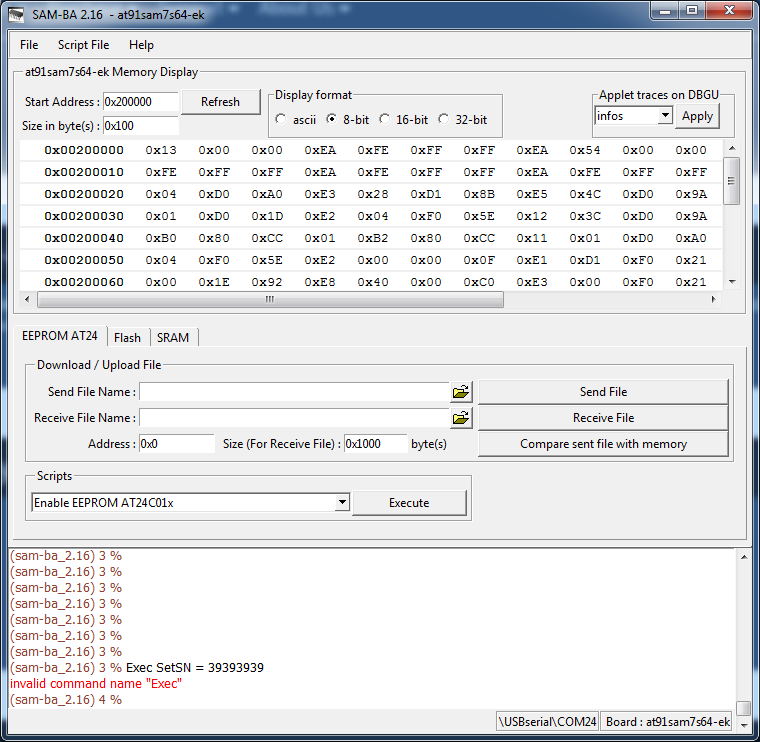
Roxy-3D
on 15 Sep 2017
You're in the Atmel BA programmer. You're done with it.
The serial number command is used in the JLink commander.
Bob-the-Kuhn
on 15 Sep 2017
I like the Segger EDU Mini page:
  EDU Mini - $18
  software - $1,240
That's an optional SystemViewPro software, not needed for just using it as a debug probe with any debugger, and Ozone is included in the EDU license. You get a reminder when you open it that you are using the EDU version, but that's all.
victorpv
on 15 Sep 2017
Thanks for pointing me back at Ozone. When I first looked at it I thought it was just running a simulation because of the license issue.
Definitely a LOT better that the debugger in PlatformIO.
I just got a kick out of the EDU Mini page. Usually options cost less than the main item, In this case it's only two orders of magnitude more.
Bob-the-Kuhn
on 15 Sep 2017
@victorpv I'm looking at the J-Link EDU Mini.
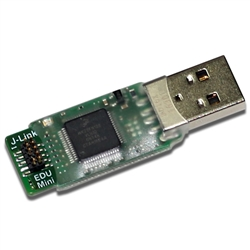
That looks usable. Do you have one of these?
It shows a 20 pin cable coming off of it.
Hopefully that can be plugged into an adapter like this: www.ebay.com/itm/New-J-link-JTAG-Adapter-Converter-ULINK2-Emulator-V8-all-ARM-for-TQ2440-MINI2440-/272009889185?epid=942513460&hash=item3f550d85a1:g:tk8AAOSwmc1XPSP5
Roxy-3D
on 15 Sep 2017
I just got a kick out of the EDU Mini page. Usually options cost less than the main item, In this case it's only two orders of magnitude more.
Also check out the other options. Like a J-Link 10-pin Needle Adapter (8.06.04) for $98
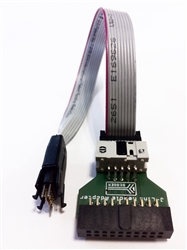
Roxy-3D
on 15 Sep 2017
I have the normal full size EDU, but also have an st-link from a nucleo turned to jlink with their software and works great. I use normal dupont female/female cables with that. Not sure what's the size of those pins in the jlink mini, but the page says it includes a target cable:
Includes:
J-Link EDU mini
.05" 19-pin target cable
Actually the page shows a picture of the cable, is a typical 2 row ribbon cable.
I wonder if there is a needle adapter to plug on top of the LPC1768...
victorpv
on 15 Sep 2017
@Roxy-3D - that adapter has a 20 pin 0.10" spacing connector. I have one of them. The edu mini has a 0.05" spacing 20 pin connector.
Bob-the-Kuhn
on 15 Sep 2017
@victorpv - when I disable the WDT the Re-ARM goes off into the weeds. Do you do anything besides comment out the line in configuration_adv.h?
Bob-the-Kuhn
on 15 Sep 2017
I commented out the code within the function that configures the WDT, so the function would get called but not enable the WDT. I didn't change the configuration at all. Didn't even comment the code in the function that reset the WDT counter, only the one that sets it up.
Forgot to say I tested that with the SBASE board, but it's using all the re-arm code like it was, only change was to the pins assigned to some steppers, so I'm almost sure the re-arm board would have worked the same
victorpv
on 15 Sep 2017
I wonder why the re-arm would go wild if it's disabled in the config, I will test that when I'm at home to see if the older 2.0 branch my code is at also does it. You are using the new one with the folder structure is that right?
victorpv
on 15 Sep 2017
Nope - I'm using one that's 2-3 weeks old.
Bob-the-Kuhn
on 15 Sep 2017
I commented out this line, or this and the one above:
https://github.com/MarlinFirmware/Marlin/blob/bugfix-2.0.x/Marlin/src/HAL/HAL_LPC1768/watchdog.cpp#L32
(not sure if that's the branch I have, now we have so many 2.0 I'm getting lost xD)
victorpv
on 15 Sep 2017
One thing that happens when the WDT trips is that I couldn't see the stack (Guess due to the hard reset), so I could not see what functions calls where there. I had to set breakpoints in the code, further and further, until the MCU would reset before getting to the line I had set the breakpoint at, then I knew what was the last point it got to successfully. With the larger Sdcards would would crash much earlier in the init process. If I extended the watchdog to 8 and counted 4 seconds before I paused I could see the MCU was busy serving a USB ISR. So it was indeed doing what expected, it just takes longer than the 4 seconds wdt with some cards for me.
victorpv
on 15 Sep 2017
Finally had some time to try this again. Using the bugfix-2.0.x-new-layout (freshly forked today), compiled for an LPC1768 and tried running a job through Repetier, it fails with the same reset send buffer block message I was getting before. Then I tried completely disabling the WDT from watchdog.cpp (I commented out the WDT_Start() routine) and that did not make any difference, it still gets hung up, sometimes within a few seconds of starting a print, sometimes within a minute or so, but it never goes for much longer than that.
Using a SanDisk Ultra 8GB Class 10 HC1 card on a Cohesion3D Mini (Smoothie) board.
Oh, when I use Pronterface to test jogging, while the jogging works, it always pops up a message saying it's busy processing. Doesn't matter if I jog 0.1mm or 10mm ...
KirAsh4
on 15 Sep 2017
@KirAsh4 I ran a test job several times without any issue in an MKS SBASE. The only difference with you maybe in the configuration settings. Also I didn't physically plug the steppers and faked the temp.
Was a 23 minutes job.
victorpv
on 15 Sep 2017
@KirAsh4 I'm afraid there has been no testing or bugfixing for the LPC1769 yet, at this point my assumption is the clock setup is not appropriate for it (I know they are not being setup correctly for 120 Mhz)
@victorpv is that an 1769? I thought it was a 1768
p3p
on 16 Sep 2017
That's right, the SBASE has a 1768, I thought the Cohesion3D had one too.
But since @KirAsh4 compiled for the 1768, I can test that bin in my board, will have the same settings he's using, so can see if it also crashes on mine.
victorpv
on 16 Sep 2017
Not sure what's the size of those pins in the jlink mini, but the page says it includes a target cable: Includes: .05" 19-pin target cable Actually the page shows a picture of the cable, is a typical 2 row ribbon cable.
@Roxy-3D - that adapter has a 20 pin 0.10" spacing connector. I have one of them. The edu mini has a 0.05" spacing 20 pin connector.
I just got that adapter from www.ebay.com/itm/New-J-link-JTAG-Adapter-Converter-ULINK2-Emulator-V8-all-ARM-for-TQ2440-MINI2440-/272009889185?epid=942513460&hash=item3f550d85a1:g:tk8AAOSwmc1XPSP5
It has 3 different 20 pin connectors. It has a male and female version of the normal 20 pin ribbon cable connectors on the board. The J-Links can plug into those. And I bed the J-Link EDU Mini can plug into the other smaller 20 pin connector.
One thing that happens when the WDT trips is that I couldn't see the stack (Guess due to the hard reset), so I could not see what functions calls where there. I had to set breakpoints in the code, further and further, until the MCU would reset before getting to the line I had set the breakpoint at, then I knew what was the last point it got to successfully.
Wouldn't it make sense to set a break point inside the watch dog routine after the condition is detected and triggered? Because then the entire stack would be available????
Roxy-3D
on 16 Sep 2017
@victorpv I'm not sure what you mean, you have an LPC1769 to test on? they may have compiled for 1768 but they're still running it on an 1769, I'm assuming the clock settings don't agree with it.
p3p
on 16 Sep 2017
@Roxy-3D The WDT causes a hardware reset, not an interrupt, so when it happens the MCU just reboots and it's looping somewhere in the bootloader code (which I dont have the source for to see what it is), and the stack is gone., so I can't say where exactly is when the WDT causes the reset, but by placing breakpoints earlier and earlier I could see at least how far in the init sequence was going before that reset happens, and I could see it was a different point, the larger the card, the earlier (wild guess, just because it would take more time reading the fat and whatever else windows does).
@p3p my idea is that if it crashes in my board, it's not something specific with his board, but rather code or configuration. Will just help rule out possible causes, and in the MKS I have the jlink plugged so I can see where it's going if it does crash. And also if it crashes, I can set the steps/mm etc to the same I use and retest, also possibly ruling out things.
victorpv
on 16 Sep 2017
@victorpv True enough I shouldn't jump to conclusions, It's just the only time that issue has come up (busy on jogging) thanks for pointing out the jlink EDU mini btw I currently have to debug on an mbed (it has built in usb dap) although it will require a bit of fiddly wiring on the rearm it will probably be worth it.
p3p
on 16 Sep 2017
The WDT causes a hardware reset, not an interrupt, so when it happens the MCU just reboots and it's looping somewhere in the bootloader code (which I dont have the source for to see what it is), and the stack is gone.
Could this be remedied by using WDT_MODE_INT_ONLY instead of WDT_MODE_RESET here? https://github.com/MarlinFirmware/Marlin/blob/dab519c0cf0fd946b24fae43f76cd4814eab093a/Marlin/src/HAL/HAL_LPC1768/watchdog.cpp#L31
One would probably also need to enable the watchdog interrupt and make it enter an endless loop.
But this way the stack could be preserved.
alex-gh
on 16 Sep 2017
I don't think kirash issue has anything to do with the WDT either, he even said the board keeps blinking sometimes, but since the MKS is close enough perhaps I can get the same reboot with that bin.
victorpv
on 16 Sep 2017
@alex-gh that would be great! I don't know anything about the LPC (mostly using STM32s), so I didn't even know the WDT could be set to trigger an interrupt. Is the ISR somewhere in the HAL or do we need to write it?
victorpv
on 16 Sep 2017
It seems the ISR is not in the HAL. It is quite possible that you don't even need to write an ISR, since the default ISR handler should be an endless loop.
You would still need to enable the watchdog interrupt in the NVIC though.
Unfortunately all of this is rather theoretical, since I have no means of testing it right now.
So I'm just going off datasheets and my previous experiences with other Cortex-M3 chips.
alex-gh
on 16 Sep 2017
You would need to write it if you wanted anything more than a empty loop, it will be weakly defined in the startup assembly (WDT_IRQHandler).
p3p
on 16 Sep 2017
I would think an endless loop should be just fine, actually better than anything that calls anywhere, that way everything is preserved like it was.
@p3p perhaps we can make that a debug option? using WDT_MODE_INT_ONLY if a debug flag is set?
victorpv
on 16 Sep 2017
@victorpv, the Cohesion I'm testing on has a 1769 on it. My understanding is there's a small number from a previous batch that has the -68 on them, but newer ones are all -69.
And this Ashley is a guy. :)
KirAsh4
on 16 Sep 2017
Sorry I'm from Spain and still get english names genders wrong everyonce in a while.
You compiled for the 1768 right? if so I can use your bin in my board since it's a 1768 too, and I compared the pins wiht the config you linked and are the same.
victorpv
on 16 Sep 2017
No te preocupes, it's just a name. Normally I go by Ash. Actually.... I wasn't even aware there's an option to choose whether to compile for -68 or -69.
KirAsh4
on 16 Sep 2017
I just did some playing with the CooCox software and their CoLinkEx debug probe. Nice GUI but no trace capabilities.
Apparently the CoLinkEx probe can support trace but not the software.
Are there any systems with trace out there that don't cost an arm & a leg?
Bob-the-Kuhn
on 16 Sep 2017
I know the 1769 can run at 120Mhz, but is there any other difference? because it may be 100% compatible with the slower 1768.
victorpv
on 16 Sep 2017
Hi All
Like some others, I've begun printing with re-arm and latest firmware.
How would you prefer that I/we report our findings? Should I create a new issue per bug/issue or report them here or consolidate them into a single issue?
apballard
on 16 Sep 2017
Bob, this is what I saw about tracing the 1768:
https://community.nxp.com/thread/389084
I seems to say that it work with the cmsis-dap, did you say you had one of those?
I used Segger systemview once to measure how long a certain ISR was taking to complete and how often it was called, was somewhat easy to use, but I don't think it's what you are looking for.
If you find some free tool for tracing post it :)
victorpv
on 16 Sep 2017
Should I create a new issue per bug/issue or report them here or consolidate them into a single issue?
I'm sure everybody has a preference. If you have a bug or something that doesn't work right... Right now here is a good place to post. This thread has the 32-Bit people in it.
Roxy-3D
on 16 Sep 2017
@Roxy-3D Thanks I'll just list some findings and experiences. Some may be a repeat of others, but at least I can corroborate some of them. I'm using a re-arm with a ramps board and pt100 sensor.
- Setting TX_BUFFER_SIZE to a non 0 value results in a build error
Compiling .pioenvs/Re-ARM/src/src/feature/bedlevel/ubl/ubl_motion.o
Marlin/src/feature/bedlevel/ubl/ubl.cpp: In static member function 'static void unified_bed_leveling::display_map(int)':
Marlin/src/feature/bedlevel/ubl/ubl.cpp:165:20: error: 'class HalSerial' has no member named 'flushTX'; did you mean 'flush'?
MYSERIAL.flushTX();
^~~~~~~
Compiling .pioenvs/Re-ARM/src/src/feature/dac/dac_dac084s085.o
*** [.pioenvs/Re-ARM/src/src/feature/bedlevel/ubl/ubl.o] Error 1
Marlin/src/feature/bedlevel/ubl/ubl_G29.cpp: In static member function 'static void unified_bed_leveling::g29_eeprom_dump()':
Marlin/src/feature/bedlevel/ubl/ubl_G29.cpp:1329:42: warning: cast to pointer from integer of different size [-Wint-to-pointer-cast]
eeprom_read_block(&cccc, (void *)kkkk, 1);
^~~~
I seem to get intermittent "G28 Z Forbidden". After a startup and various startup procedures I can run G28 a number of times. However at seemingly random times, the XYZ on the lcd start flashing then if I run a G28, XY home fine then G28 Z Forbidden will appear on the screen. Many times I'll start up and then begin with a G28 -> G29 A -> G29 L01 -> G1 Z0 -> M851 -> M851 Z-xxx then G28 will no longer work. Other times it goes through fine, but after a print G28 will no longer work.
G26 seems to skip steps in the x direction, however this is not a problem on a normal print. I'll send some pictures as soon as possible.
The problem already mentioned, that of spikes on temperature readings. I have implemented a 100uf cap and software filtering.
Another previously mentioned issue, random freezing during prints. It would seem that the freeze happens on the serial port, it stops responding to gcode and stops sending status updates. Sometimes it happens within the first layer of a print, other times after about an hour of printing.
apballard
on 16 Sep 2017
@Roxy-3D this file has the M100 modifications I have been using with the re-arm and an stm32f1:
https://github.com/victorpv/Marlin-STM32-libmaple/blob/master/M100_Free_Mem_Chk.cpp
And these have the changes to print words of 32bits:
https://github.com/victorpv/Marlin-STM32-libmaple/blob/master/hex_print_routines.cpp
https://github.com/victorpv/Marlin-STM32-libmaple/blob/master/hex_print_routines.h
But I haven't tested that with an AVR board, so may not work after the changes :( perhaps a solution is to make this conditional depending on the architecture?:
static char _hex[11] = "0x00000000";
char* hex_word(const uint32_t w) {
_hex[2] = hex_nybble(w >> 28);
_hex[3] = hex_nybble(w >> 24);
_hex[4] = hex_nybble(w >> 20);
_hex[5] = hex_nybble(w >> 16);
_hex[6] = hex_nybble(w >> 12);
_hex[7] = hex_nybble(w >> 8);
_hex[8] = hex_nybble(w >> 4);
_hex[9] = hex_nybble(w);
return &_hex[2];
}
victorpv
on 16 Sep 2017
I know the 1769 can run at 120Mhz, but is there any other difference? because it may be 100% compatible with the slower 1768.
@victorpv They should be 100% compatible other than the clock setting as far as I'm aware.
@apballard Thank you for the feedback it really helps, heres some feedback feedback (not solutions ;) )
TX_BUFFER_SIZE is actually pointless on the lpc1768 it has a 128 byte tx/rx buffers by default in the Serial class, but the flushTX method should be implemented for compatibility.
I'm unsure about the Z Forbidden warnings .. we try not to change any Marlin logic or have any independent code paths so I'm not sure how the platform implementation effects this.
The stepper control signals will have faster pulses with LPC1768 it could be a problem for your drivers but then it wouldn't be only with that command, you could try setting a pulse delay in the config though.
Random freezing is definitely the most worrying problem you are having, sounds like the usb stack is flaking out, do you have a lot of unshielded wiring? is your usb cable shielded and away from noise sources? I wouldn't be surprised if it was just a problem with the usb stack though, or something else entirely.
p3p
on 16 Sep 2017
@Bob-the-Kuhn Here is what I know with regards to tracing:
While it is very easy to capture a trace, after all it is just UART or manchester encoded data, displaying it in a pretty and usable way is mostly a feature of premium IDEs.
The trace output is very versatile. If you just want to use it for printf-stlye string output you can just connect it to a serial port and make it display all the incoming text.
If you want to do actual execution tracing you can either get a premium IDE or follow this example in order to capture and decode an execution trace using a logic analyzer and sigrok.
EDIT: Here is an example of how to enable tracing on the MCU. It is for STM32, but it should be similar for the LPCs
EDIT2: Here is a tool that might be useful in SWO decoding: https://github.com/mubes/orbuculum
alex-gh
on 16 Sep 2017
@p3p in that case the binary for the lpc1768 should work fine on both.
@KirAsh4 can you attach your bin file so I can flash it to my board and see if I get the same issues? I'm interested to see what I get, since I get the sdcard lockups very few people gets, but instead my fake prints complete without any hicup every time. I run one like 5 times with pronterface just to see if it would crash, or some runs would take longer or shorter should the code took a different path, but they were consistent, then run the same with an STM32F1 board with the same step/mm settings and took exactly the same time, so both HALs were behaving in a pretty similar way. I hope to get the MKS connected to the printer this weekend, would like to give a shot to your bin before I start messing with that.
victorpv
on 16 Sep 2017
@alex-gh - thanks for the great pointers.
I ran into two problems with the sigrok approach:
- I couldn't select any of the ARM decoders. They're in the package but they don't appear in the menu.
- Apparently you need to program the debug macrocells. I wasn't able to find anything on this.
The orbuculum link is very interesting. A $40 board that allows real instruction tracing. That's only $1,500 less than the nearest competitor. The SWO viewers at best offer PC sampling of about 1 every 64.
EDIT 1 - I've figured out how to use the ARM decoders. I also found out that it can't use the trace port so it's limited to PC sampling via the SWO pin.
Bob-the-Kuhn
on 17 Sep 2017
Well yes, the solutions I described all work with the SWO pin since the trace pins are all in use on Re-ARM
The orbuculum link is very interesting. A $40 board that allows real instruction tracing. That's only $1,500 less than the nearest competitor. The SWO viewers at best offer PC sampling of about 1 every 64.
Orbuculum is just software. It can work with
the Black Magic Debug Probe (BMP)
the SEGGER JLink
generic USB TTL Serial Interfaces
That means any old USB-Serial adapter would do for tracing. But the faster they are the better. An FT2232 based converter can sample at 12Mb/s with Orbuculum.
It is possible to get complete instruction tracing using just SWO, but you would need to slow the CPU clock for that.
If you don't need that much granularity you can use the DWT to track when the CPU enters and leaves functions and interrupts.
Here is some more reading material on cortex debugging from the author of Orbuculum, I found it highly informative.
--
I hope the deep debugging discussion is not getting too off topic for this thread. If it is it might be best to continue in another one, for example here: https://github.com/MarlinFirmware/Marlin/issues/7511
alex-gh
on 17 Sep 2017
The LPC1768 CMSIS driver in the framework is a giant pile of mess I just dropped straight in, I'm reluctant to have modifications to it unless they are bugfixes
@p3p I've figured out a way to have PIO use different compiler settings for the main Marlin source and the frameworks/libs, which will let us have less stringent warning settings for the third party components we're using. However, in order to make this work, we would need to move the frameworks folder to be a sister folder of the Marlin folder, instead of a child folder. If that works for you, then perhaps @thinkyhead can incorporate that change into his "new layout" effort, and then I can provide the necessary patches to the platformio.ini file in my warning cleanup PR.
tcm0116
on 17 Sep 2017
@alex-gh - yes, #7511 is a good place for this.
Bob-the-Kuhn
on 17 Sep 2017
Here ya go @victorpv. The following steps were followed:
- changed MOTHERBOARD to 'BOARDS_RAMPS_14_RE_ARM_EFB'
- changed pins in pins_RAMPS_RE_ARM.h
Executed PIO Clean (Re-ARM)
Executed PIO Build (Re-ARM)
KirAsh4
on 17 Sep 2017
Hi again, bit more of an update.
G28 Z Forbidden
It would seem that this problem occurs after a M851. If I execute a M851 then immediately (I can type quickly) run G28 Z, it's fine. But if I Run a G28 as is, it homes x and y but by the time the z home starts it then fails, because it takes too long. It would seem that it might not be the m851 in itself, sine it completes, and the axis xyz invalidate shortly thereafter.serial "lockup"
I ran into this problem twice yesterday, both times it seems the serial itself did not lock up, however on the serial after acknowledging a gcode (regular extrusion gcode) command it begins to say echo :busy: processing repeatedly not accepting any commands and not sending updates.
apballard
on 18 Sep 2017
That 'echo: busy: processing' message is the same thing I'm seeing running on an LPC1769 using Pronterface.
KirAsh4
on 18 Sep 2017
I should have added
- babystepping
Not sure if anyone has babystepping working on re-arm. I enabled it, and the option to make it accessible through double click, however I could not get it to work from double click. However in hindsight I did not try activating it through regular menu options. Will try tonight to see if it's even there
apballard
on 18 Sep 2017
So rather than a lockup seems to be getting stuck looping somewhere?
@KirAsh4 I haven't had the change et to load you bin to my board. One question, did you set the thermistors to fake ones so I can run it without thermistors?
victorpv
on 18 Sep 2017
@victorpv No, I just comment out G28, M107, M109, and M190 commands at the beginning of the gcode. And also issue a M302 P1 (cold extrusion).
KirAsh4
on 18 Sep 2017
So rather than a lockup seems to be getting stuck looping somewhere?
@victorpv yeah that's the best way to describe it.
apballard
on 19 Sep 2017
@KirAsh4 I loaded your bin today, commented out the m190, m109, m104 and m140 commands in a gcode file, then sent M302 P1 and printed the file. Completed in 21 minutes without issues. Repeated the test, and completed again without issues.
These files are sliced with an old version of slic3r that came with pronterface.
Can you upload one of the files that hangs for you?
EDIT: I restarted the board, and repeated with a different gcode file, completed in 19 minutes.
victorpv
on 21 Sep 2017
@p3p I've been working on cleaning up the compiler warnings, and in the process of randomly enabling features, I've discovered that we don't yet have a replacement for the TWI/I2C library defined in Wire.h in the Arduino framework. This breaks things like DIGIPOT_I2C, I2C_POSITION_ENCODERS, BLINKM, etc. Do you know if anyone's started looking into this?
tcm0116
on 24 Sep 2017
With the 2.0 re-org system my linker thinks the start of FLASH is 0x04000. Since VTOR is pointing at 0 the program immediately goes off into the weeds.
How do I force the linker to put the vector table at 0?
I'm using PlatformIO within Atom.
Bob-the-Kuhn
on 24 Sep 2017
@Bob-the-Kuhn You really should not.
The bootloader lives in the first 16k of flash. It has its own vector table there.
The bootloader should have set the VTOR to 0x4000 before the start of user application though.
Are you sure your bootloader is still intact?
EDIT: But sure if you really want to use your board without bootloader
Just uncomment the first line and comment the following line.
https://github.com/MarlinFirmware/Marlin/blob/1ab679b1d2167556933da875177d42849b3130b2/frameworks/CMSIS/LPC1768/Re-ARM/LPC1768.ld#L4-L5
Personally I have not tried it, but it should put everything at the start of the flash. Once again: Please keep in mind that it will delete the bootloader.
alex-gh
on 24 Sep 2017
Bob-the-Kuhn
on 24 Sep 2017
alex-gh
on 24 Sep 2017
Bob-the-Kuhn
on 24 Sep 2017
p3p
on 24 Sep 2017
alex-gh
on 24 Sep 2017
 xC0000005
on 25 Sep 2017
apballard
on 25 Sep 2017
p3p
on 25 Sep 2017
bobc
on 25 Sep 2017
p3p
on 25 Sep 2017
alex-gh
on 25 Sep 2017
p3p
on 25 Sep 2017
xC0000005
on 25 Sep 2017
apballard
on 26 Sep 2017
tcm0116
on 26 Sep 2017
Roxy-3D
on 26 Sep 2017
Bob-the-Kuhn
on 26 Sep 2017
apballard
on 26 Sep 2017
victorpv
on 26 Sep 2017
victorpv
on 26 Sep 2017
KirAsh4
on 27 Sep 2017
tcm0116
on 27 Sep 2017
tcm0116
on 27 Sep 2017
victorpv
on 27 Sep 2017
victorpv
on 27 Sep 2017
xC0000005
on 27 Sep 2017
Roxy-3D
on 27 Sep 2017
victorpv
on 27 Sep 2017
Roxy-3D
on 27 Sep 2017
apballard
on 27 Sep 2017
victorpv
on 27 Sep 2017
Bob-the-Kuhn
on 27 Sep 2017
p3p
on 27 Sep 2017
apballard
on 27 Sep 2017
apballard
on 27 Sep 2017
xC0000005
on 27 Sep 2017
p3p
on 27 Sep 2017
apballard
on 27 Sep 2017
p3p
on 27 Sep 2017
apballard
on 27 Sep 2017
Bob-the-Kuhn
on 27 Sep 2017
apballard
on 27 Sep 2017
Roxy-3D
on 27 Sep 2017
p3p
on 27 Sep 2017
p3p
on 27 Sep 2017
apballard
on 27 Sep 2017
psavva
on 27 Sep 2017
xC0000005
on 25 Sep 2017
apballard
on 25 Sep 2017
p3p
on 25 Sep 2017
bobc
on 25 Sep 2017
p3p
on 25 Sep 2017
alex-gh
on 25 Sep 2017
p3p
on 25 Sep 2017
xC0000005
on 25 Sep 2017
apballard
on 26 Sep 2017
tcm0116
on 26 Sep 2017
Roxy-3D
on 26 Sep 2017
Bob-the-Kuhn
on 26 Sep 2017
apballard
on 26 Sep 2017
victorpv
on 26 Sep 2017
victorpv
on 26 Sep 2017
KirAsh4
on 27 Sep 2017
tcm0116
on 27 Sep 2017
tcm0116
on 27 Sep 2017
victorpv
on 27 Sep 2017
victorpv
on 27 Sep 2017
xC0000005
on 27 Sep 2017
Roxy-3D
on 27 Sep 2017
victorpv
on 27 Sep 2017
Roxy-3D
on 27 Sep 2017
apballard
on 27 Sep 2017
victorpv
on 27 Sep 2017
Bob-the-Kuhn
on 27 Sep 2017
p3p
on 27 Sep 2017
apballard
on 27 Sep 2017
apballard
on 27 Sep 2017
xC0000005
on 27 Sep 2017
p3p
on 27 Sep 2017
apballard
on 27 Sep 2017
p3p
on 27 Sep 2017
apballard
on 27 Sep 2017
Bob-the-Kuhn
on 27 Sep 2017
apballard
on 27 Sep 2017
Roxy-3D
on 27 Sep 2017
p3p
on 27 Sep 2017
p3p
on 27 Sep 2017
apballard
on 27 Sep 2017
psavva
on 27 Sep 2017
 Sebastianv650
on 27 Sep 2017
Bob-the-Kuhn
on 27 Sep 2017
p3p
on 27 Sep 2017
p3p
on 27 Sep 2017
victorpv
on 27 Sep 2017
p3p
on 27 Sep 2017
tcm0116
on 27 Sep 2017
p3p
on 27 Sep 2017
victorpv
on 27 Sep 2017
p3p
on 28 Sep 2017
victorpv
on 28 Sep 2017
Bob-the-Kuhn
on 28 Sep 2017
victorpv
on 28 Sep 2017
tcm0116
on 28 Sep 2017
victorpv
on 28 Sep 2017
tcm0116
on 28 Sep 2017
Bob-the-Kuhn
on 28 Sep 2017
victorpv
on 28 Sep 2017
tcm0116
on 28 Sep 2017
Bob-the-Kuhn
on 28 Sep 2017
victorpv
on 28 Sep 2017
tcm0116
on 28 Sep 2017
apballard
on 28 Sep 2017
victorpv
on 28 Sep 2017
p3p
on 28 Sep 2017
tcm0116
on 28 Sep 2017
p3p
on 28 Sep 2017
Bob-the-Kuhn
on 28 Sep 2017
xC0000005
on 28 Sep 2017
Bob-the-Kuhn
on 28 Sep 2017
p3p
on 28 Sep 2017
victorpv
on 28 Sep 2017
victorpv
on 28 Sep 2017
victorpv
on 28 Sep 2017
Bob-the-Kuhn
on 28 Sep 2017
Roxy-3D
on 28 Sep 2017
victorpv
on 28 Sep 2017
tcm0116
on 28 Sep 2017
tcm0116
on 28 Sep 2017
victorpv
on 28 Sep 2017
victorpv
on 29 Sep 2017
apballard
on 29 Sep 2017
apballard
on 29 Sep 2017
Bergerac56
on 29 Sep 2017
p3p
on 29 Sep 2017
teemuatlut
on 29 Sep 2017
apballard
on 29 Sep 2017
Bob-the-Kuhn
on 29 Sep 2017
alex-gh
on 29 Sep 2017
victorpv
on 29 Sep 2017
Bob-the-Kuhn
on 29 Sep 2017
Bob-the-Kuhn
on 29 Sep 2017
victorpv
on 29 Sep 2017
alex-gh
on 29 Sep 2017
Bob-the-Kuhn
on 29 Sep 2017
Bob-the-Kuhn
on 29 Sep 2017
alex-gh
on 29 Sep 2017
p3p
on 29 Sep 2017
Roxy-3D
on 29 Sep 2017
tcm0116
on 29 Sep 2017
Bob-the-Kuhn
on 29 Sep 2017
Bob-the-Kuhn
on 29 Sep 2017
victorpv
on 29 Sep 2017
tcm0116
on 29 Sep 2017
victorpv
on 29 Sep 2017
Bob-the-Kuhn
on 30 Sep 2017
p3p
on 30 Sep 2017
victorpv
on 30 Sep 2017
Bob-the-Kuhn
on 30 Sep 2017
Bob-the-Kuhn
on 30 Sep 2017
Bergerac56
on 30 Sep 2017
Roxy-3D
on 30 Sep 2017
Bergerac56
on 1 Oct 2017
tcm0116
on 1 Oct 2017
victorpv
on 2 Oct 2017
Roxy-3D
on 2 Oct 2017
tcm0116
on 2 Oct 2017
Roxy-3D
on 2 Oct 2017
victorpv
on 3 Oct 2017
Roxy-3D
on 3 Oct 2017
victorpv
on 3 Oct 2017
tcm0116
on 3 Oct 2017
Bob-the-Kuhn
on 3 Oct 2017
teemuatlut
on 3 Oct 2017
victorpv
on 3 Oct 2017
Bob-the-Kuhn
on 3 Oct 2017
apballard
on 4 Oct 2017
p3p
on 4 Oct 2017
apballard
on 5 Oct 2017
p3p
on 5 Oct 2017
Roxy-3D
on 6 Oct 2017
apballard
on 6 Oct 2017
Sebastianv650
on 27 Sep 2017
Bob-the-Kuhn
on 27 Sep 2017
p3p
on 27 Sep 2017
p3p
on 27 Sep 2017
victorpv
on 27 Sep 2017
p3p
on 27 Sep 2017
tcm0116
on 27 Sep 2017
p3p
on 27 Sep 2017
victorpv
on 27 Sep 2017
p3p
on 28 Sep 2017
victorpv
on 28 Sep 2017
Bob-the-Kuhn
on 28 Sep 2017
victorpv
on 28 Sep 2017
tcm0116
on 28 Sep 2017
victorpv
on 28 Sep 2017
tcm0116
on 28 Sep 2017
Bob-the-Kuhn
on 28 Sep 2017
victorpv
on 28 Sep 2017
tcm0116
on 28 Sep 2017
Bob-the-Kuhn
on 28 Sep 2017
victorpv
on 28 Sep 2017
tcm0116
on 28 Sep 2017
apballard
on 28 Sep 2017
victorpv
on 28 Sep 2017
p3p
on 28 Sep 2017
tcm0116
on 28 Sep 2017
p3p
on 28 Sep 2017
Bob-the-Kuhn
on 28 Sep 2017
xC0000005
on 28 Sep 2017
Bob-the-Kuhn
on 28 Sep 2017
p3p
on 28 Sep 2017
victorpv
on 28 Sep 2017
victorpv
on 28 Sep 2017
victorpv
on 28 Sep 2017
Bob-the-Kuhn
on 28 Sep 2017
Roxy-3D
on 28 Sep 2017
victorpv
on 28 Sep 2017
tcm0116
on 28 Sep 2017
tcm0116
on 28 Sep 2017
victorpv
on 28 Sep 2017
victorpv
on 29 Sep 2017
apballard
on 29 Sep 2017
apballard
on 29 Sep 2017
Bergerac56
on 29 Sep 2017
p3p
on 29 Sep 2017
teemuatlut
on 29 Sep 2017
apballard
on 29 Sep 2017
Bob-the-Kuhn
on 29 Sep 2017
alex-gh
on 29 Sep 2017
victorpv
on 29 Sep 2017
Bob-the-Kuhn
on 29 Sep 2017
Bob-the-Kuhn
on 29 Sep 2017
victorpv
on 29 Sep 2017
alex-gh
on 29 Sep 2017
Bob-the-Kuhn
on 29 Sep 2017
Bob-the-Kuhn
on 29 Sep 2017
alex-gh
on 29 Sep 2017
p3p
on 29 Sep 2017
Roxy-3D
on 29 Sep 2017
tcm0116
on 29 Sep 2017
Bob-the-Kuhn
on 29 Sep 2017
Bob-the-Kuhn
on 29 Sep 2017
victorpv
on 29 Sep 2017
tcm0116
on 29 Sep 2017
victorpv
on 29 Sep 2017
Bob-the-Kuhn
on 30 Sep 2017
p3p
on 30 Sep 2017
victorpv
on 30 Sep 2017
Bob-the-Kuhn
on 30 Sep 2017
Bob-the-Kuhn
on 30 Sep 2017
Bergerac56
on 30 Sep 2017
Roxy-3D
on 30 Sep 2017
Bergerac56
on 1 Oct 2017
tcm0116
on 1 Oct 2017
victorpv
on 2 Oct 2017
Roxy-3D
on 2 Oct 2017
tcm0116
on 2 Oct 2017
Roxy-3D
on 2 Oct 2017
victorpv
on 3 Oct 2017
Roxy-3D
on 3 Oct 2017
victorpv
on 3 Oct 2017
tcm0116
on 3 Oct 2017
Bob-the-Kuhn
on 3 Oct 2017
teemuatlut
on 3 Oct 2017
victorpv
on 3 Oct 2017
Bob-the-Kuhn
on 3 Oct 2017
apballard
on 4 Oct 2017
p3p
on 4 Oct 2017
apballard
on 5 Oct 2017
p3p
on 5 Oct 2017
Roxy-3D
on 6 Oct 2017
apballard
on 6 Oct 2017
 Spawn32
on 6 Oct 2017
tcm0116
on 6 Oct 2017
victorpv
on 6 Oct 2017
Spawn32
on 6 Oct 2017
Roxy-3D
on 6 Oct 2017
tcm0116
on 6 Oct 2017
Spawn32
on 6 Oct 2017
tcm0116
on 6 Oct 2017
p3p
on 6 Oct 2017
victorpv
on 6 Oct 2017
victorpv
on 6 Oct 2017
Spawn32
on 6 Oct 2017
Roxy-3D
on 6 Oct 2017
mperdue
on 6 Oct 2017
p3p
on 6 Oct 2017
p3p
on 6 Oct 2017
Roxy-3D
on 6 Oct 2017
tcm0116
on 6 Oct 2017
p3p
on 6 Oct 2017
Roxy-3D
on 7 Oct 2017
p3p
on 7 Oct 2017
Roxy-3D
on 7 Oct 2017
tcm0116
on 7 Oct 2017
victorpv
on 7 Oct 2017
Roxy-3D
on 7 Oct 2017
Spawn32
on 7 Oct 2017
p3p
on 7 Oct 2017
Spawn32
on 7 Oct 2017
p3p
on 7 Oct 2017
Spawn32
on 7 Oct 2017
p3p
on 7 Oct 2017
victorpv
on 7 Oct 2017
Spawn32
on 7 Oct 2017
Spawn32
on 6 Oct 2017
tcm0116
on 6 Oct 2017
victorpv
on 6 Oct 2017
Spawn32
on 6 Oct 2017
Roxy-3D
on 6 Oct 2017
tcm0116
on 6 Oct 2017
Spawn32
on 6 Oct 2017
tcm0116
on 6 Oct 2017
p3p
on 6 Oct 2017
victorpv
on 6 Oct 2017
victorpv
on 6 Oct 2017
Spawn32
on 6 Oct 2017
Roxy-3D
on 6 Oct 2017
mperdue
on 6 Oct 2017
p3p
on 6 Oct 2017
p3p
on 6 Oct 2017
Roxy-3D
on 6 Oct 2017
tcm0116
on 6 Oct 2017
p3p
on 6 Oct 2017
Roxy-3D
on 7 Oct 2017
p3p
on 7 Oct 2017
Roxy-3D
on 7 Oct 2017
tcm0116
on 7 Oct 2017
victorpv
on 7 Oct 2017
Roxy-3D
on 7 Oct 2017
Spawn32
on 7 Oct 2017
p3p
on 7 Oct 2017
Spawn32
on 7 Oct 2017
p3p
on 7 Oct 2017
Spawn32
on 7 Oct 2017
p3p
on 7 Oct 2017
victorpv
on 7 Oct 2017
Spawn32
on 7 Oct 2017
 simon-jouet
on 7 Oct 2017
tcm0116
on 8 Oct 2017
tcm0116
on 8 Oct 2017
Spawn32
on 8 Oct 2017
victorpv
on 8 Oct 2017
Spawn32
on 8 Oct 2017
Roxy-3D
on 8 Oct 2017
tcm0116
on 8 Oct 2017
Roxy-3D
on 8 Oct 2017
Spawn32
on 8 Oct 2017
Bob-the-Kuhn
on 9 Oct 2017
Bob-the-Kuhn
on 9 Oct 2017
Spawn32
on 9 Oct 2017
simon-jouet
on 7 Oct 2017
tcm0116
on 8 Oct 2017
tcm0116
on 8 Oct 2017
Spawn32
on 8 Oct 2017
victorpv
on 8 Oct 2017
Spawn32
on 8 Oct 2017
Roxy-3D
on 8 Oct 2017
tcm0116
on 8 Oct 2017
Roxy-3D
on 8 Oct 2017
Spawn32
on 8 Oct 2017
Bob-the-Kuhn
on 9 Oct 2017
Bob-the-Kuhn
on 9 Oct 2017
Spawn32
on 9 Oct 2017
 dapperfu
on 9 Oct 2017
Spawn32
on 9 Oct 2017
Roxy-3D
on 9 Oct 2017
Spawn32
on 9 Oct 2017
tcm0116
on 9 Oct 2017
Spawn32
on 9 Oct 2017
Roxy-3D
on 9 Oct 2017
Spawn32
on 9 Oct 2017
Bob-the-Kuhn
on 9 Oct 2017
Bob-the-Kuhn
on 9 Oct 2017
Roxy-3D
on 9 Oct 2017
Spawn32
on 10 Oct 2017
Spawn32
on 10 Oct 2017
Spawn32
on 10 Oct 2017
teemuatlut
on 10 Oct 2017
p3p
on 10 Oct 2017
Spawn32
on 10 Oct 2017
Spawn32
on 10 Oct 2017
simon-jouet
on 10 Oct 2017
Spawn32
on 10 Oct 2017
simon-jouet
on 10 Oct 2017
Spawn32
on 10 Oct 2017
p3p
on 10 Oct 2017
Spawn32
on 10 Oct 2017
Spawn32
on 10 Oct 2017
p3p
on 10 Oct 2017
tcm0116
on 10 Oct 2017
Spawn32
on 10 Oct 2017
Roxy-3D
on 10 Oct 2017
tcm0116
on 11 Oct 2017
Bob-the-Kuhn
on 11 Oct 2017
tcm0116
on 11 Oct 2017
Spawn32
on 11 Oct 2017
tcm0116
on 11 Oct 2017
Spawn32
on 11 Oct 2017
Bob-the-Kuhn
on 11 Oct 2017
Spawn32
on 11 Oct 2017
Roxy-3D
on 11 Oct 2017
Spawn32
on 11 Oct 2017
victorpv
on 11 Oct 2017
Spawn32
on 11 Oct 2017
Bob-the-Kuhn
on 11 Oct 2017
victorpv
on 11 Oct 2017
Roxy-3D
on 11 Oct 2017
Spawn32
on 11 Oct 2017
victorpv
on 11 Oct 2017
Spawn32
on 11 Oct 2017
Bob-the-Kuhn
on 11 Oct 2017
p3p
on 11 Oct 2017
Spawn32
on 11 Oct 2017
p3p
on 11 Oct 2017
Spawn32
on 11 Oct 2017
Roxy-3D
on 11 Oct 2017
victorpv
on 11 Oct 2017
Spawn32
on 11 Oct 2017
Bergerac56
on 11 Oct 2017
Roxy-3D
on 11 Oct 2017
tcm0116
on 11 Oct 2017
p3p
on 11 Oct 2017
Roxy-3D
on 11 Oct 2017
Roxy-3D
on 11 Oct 2017
Spawn32
on 11 Oct 2017
p3p
on 11 Oct 2017
Roxy-3D
on 11 Oct 2017
tcm0116
on 11 Oct 2017
Roxy-3D
on 11 Oct 2017
p3p
on 11 Oct 2017
Roxy-3D
on 11 Oct 2017
Spawn32
on 11 Oct 2017
Spawn32
on 12 Oct 2017
p3p
on 12 Oct 2017
apballard
on 12 Oct 2017
apballard
on 12 Oct 2017
xC0000005
on 12 Oct 2017
Spawn32
on 12 Oct 2017
p3p
on 12 Oct 2017
Spawn32
on 14 Oct 2017
Roxy-3D
on 14 Oct 2017
Spawn32
on 14 Oct 2017
tcm0116
on 14 Oct 2017
Spawn32
on 14 Oct 2017
tcm0116
on 14 Oct 2017
p3p
on 14 Oct 2017
p3p
on 14 Oct 2017
Spawn32
on 14 Oct 2017
tcm0116
on 15 Oct 2017
p3p
on 15 Oct 2017
tcm0116
on 15 Oct 2017
p3p
on 15 Oct 2017
tcm0116
on 15 Oct 2017
Spawn32
on 15 Oct 2017
tcm0116
on 16 Oct 2017
Spawn32
on 16 Oct 2017
tcm0116
on 16 Oct 2017
Spawn32
on 16 Oct 2017
tcm0116
on 16 Oct 2017
Spawn32
on 16 Oct 2017
apballard
on 16 Oct 2017
p3p
on 16 Oct 2017
dapperfu
on 9 Oct 2017
Spawn32
on 9 Oct 2017
Roxy-3D
on 9 Oct 2017
Spawn32
on 9 Oct 2017
tcm0116
on 9 Oct 2017
Spawn32
on 9 Oct 2017
Roxy-3D
on 9 Oct 2017
Spawn32
on 9 Oct 2017
Bob-the-Kuhn
on 9 Oct 2017
Bob-the-Kuhn
on 9 Oct 2017
Roxy-3D
on 9 Oct 2017
Spawn32
on 10 Oct 2017
Spawn32
on 10 Oct 2017
Spawn32
on 10 Oct 2017
teemuatlut
on 10 Oct 2017
p3p
on 10 Oct 2017
Spawn32
on 10 Oct 2017
Spawn32
on 10 Oct 2017
simon-jouet
on 10 Oct 2017
Spawn32
on 10 Oct 2017
simon-jouet
on 10 Oct 2017
Spawn32
on 10 Oct 2017
p3p
on 10 Oct 2017
Spawn32
on 10 Oct 2017
Spawn32
on 10 Oct 2017
p3p
on 10 Oct 2017
tcm0116
on 10 Oct 2017
Spawn32
on 10 Oct 2017
Roxy-3D
on 10 Oct 2017
tcm0116
on 11 Oct 2017
Bob-the-Kuhn
on 11 Oct 2017
tcm0116
on 11 Oct 2017
Spawn32
on 11 Oct 2017
tcm0116
on 11 Oct 2017
Spawn32
on 11 Oct 2017
Bob-the-Kuhn
on 11 Oct 2017
Spawn32
on 11 Oct 2017
Roxy-3D
on 11 Oct 2017
Spawn32
on 11 Oct 2017
victorpv
on 11 Oct 2017
Spawn32
on 11 Oct 2017
Bob-the-Kuhn
on 11 Oct 2017
victorpv
on 11 Oct 2017
Roxy-3D
on 11 Oct 2017
Spawn32
on 11 Oct 2017
victorpv
on 11 Oct 2017
Spawn32
on 11 Oct 2017
Bob-the-Kuhn
on 11 Oct 2017
p3p
on 11 Oct 2017
Spawn32
on 11 Oct 2017
p3p
on 11 Oct 2017
Spawn32
on 11 Oct 2017
Roxy-3D
on 11 Oct 2017
victorpv
on 11 Oct 2017
Spawn32
on 11 Oct 2017
Bergerac56
on 11 Oct 2017
Roxy-3D
on 11 Oct 2017
tcm0116
on 11 Oct 2017
p3p
on 11 Oct 2017
Roxy-3D
on 11 Oct 2017
Roxy-3D
on 11 Oct 2017
Spawn32
on 11 Oct 2017
p3p
on 11 Oct 2017
Roxy-3D
on 11 Oct 2017
tcm0116
on 11 Oct 2017
Roxy-3D
on 11 Oct 2017
p3p
on 11 Oct 2017
Roxy-3D
on 11 Oct 2017
Spawn32
on 11 Oct 2017
Spawn32
on 12 Oct 2017
p3p
on 12 Oct 2017
apballard
on 12 Oct 2017
apballard
on 12 Oct 2017
xC0000005
on 12 Oct 2017
Spawn32
on 12 Oct 2017
p3p
on 12 Oct 2017
Spawn32
on 14 Oct 2017
Roxy-3D
on 14 Oct 2017
Spawn32
on 14 Oct 2017
tcm0116
on 14 Oct 2017
Spawn32
on 14 Oct 2017
tcm0116
on 14 Oct 2017
p3p
on 14 Oct 2017
p3p
on 14 Oct 2017
Spawn32
on 14 Oct 2017
tcm0116
on 15 Oct 2017
p3p
on 15 Oct 2017
tcm0116
on 15 Oct 2017
p3p
on 15 Oct 2017
tcm0116
on 15 Oct 2017
Spawn32
on 15 Oct 2017
tcm0116
on 16 Oct 2017
Spawn32
on 16 Oct 2017
tcm0116
on 16 Oct 2017
Spawn32
on 16 Oct 2017
tcm0116
on 16 Oct 2017
Spawn32
on 16 Oct 2017
apballard
on 16 Oct 2017
p3p
on 16 Oct 2017
 AnHardt
on 16 Oct 2017
tcm0116
on 16 Oct 2017
victorpv
on 16 Oct 2017
tcm0116
on 16 Oct 2017
AnHardt
on 16 Oct 2017
xC0000005
on 16 Oct 2017
AnHardt
on 16 Oct 2017
victorpv
on 16 Oct 2017
tcm0116
on 17 Oct 2017
AnHardt
on 17 Oct 2017
victorpv
on 17 Oct 2017
tcm0116
on 17 Oct 2017
AnHardt
on 17 Oct 2017
victorpv
on 18 Oct 2017
tcm0116
on 18 Oct 2017
AnHardt
on 18 Oct 2017
victorpv
on 18 Oct 2017
AnHardt
on 18 Oct 2017
victorpv
on 18 Oct 2017
psavva
on 18 Oct 2017
AnHardt
on 19 Oct 2017
AnHardt
on 19 Oct 2017
victorpv
on 19 Oct 2017
Roxy-3D
on 19 Oct 2017
p3p
on 19 Oct 2017
Roxy-3D
on 19 Oct 2017
xC0000005
on 22 Oct 2017
AnHardt
on 16 Oct 2017
tcm0116
on 16 Oct 2017
victorpv
on 16 Oct 2017
tcm0116
on 16 Oct 2017
AnHardt
on 16 Oct 2017
xC0000005
on 16 Oct 2017
AnHardt
on 16 Oct 2017
victorpv
on 16 Oct 2017
tcm0116
on 17 Oct 2017
AnHardt
on 17 Oct 2017
victorpv
on 17 Oct 2017
tcm0116
on 17 Oct 2017
AnHardt
on 17 Oct 2017
victorpv
on 18 Oct 2017
tcm0116
on 18 Oct 2017
AnHardt
on 18 Oct 2017
victorpv
on 18 Oct 2017
AnHardt
on 18 Oct 2017
victorpv
on 18 Oct 2017
psavva
on 18 Oct 2017
AnHardt
on 19 Oct 2017
AnHardt
on 19 Oct 2017
victorpv
on 19 Oct 2017
Roxy-3D
on 19 Oct 2017
p3p
on 19 Oct 2017
Roxy-3D
on 19 Oct 2017
xC0000005
on 22 Oct 2017
 luc-github
on 22 Oct 2017
Roxy-3D
on 22 Oct 2017
luc-github
on 22 Oct 2017
Roxy-3D
on 22 Oct 2017
luc-github
on 22 Oct 2017
tcm0116
on 22 Oct 2017
AnHardt
on 22 Oct 2017
luc-github
on 22 Oct 2017
xC0000005
on 22 Oct 2017
tcm0116
on 23 Oct 2017
luc-github
on 23 Oct 2017
tcm0116
on 23 Oct 2017
luc-github
on 23 Oct 2017
Spawn32
on 24 Oct 2017
Roxy-3D
on 24 Oct 2017
victorpv
on 25 Oct 2017
victorpv
on 25 Oct 2017
Roxy-3D
on 25 Oct 2017
p3p
on 25 Oct 2017
luc-github
on 25 Oct 2017
Spawn32
on 25 Oct 2017
xC0000005
on 25 Oct 2017
victorpv
on 25 Oct 2017
AnHardt
on 26 Oct 2017
victorpv
on 27 Oct 2017
Roxy-3D
on 27 Oct 2017
victorpv
on 27 Oct 2017
Roxy-3D
on 27 Oct 2017
victorpv
on 27 Oct 2017
Roxy-3D
on 27 Oct 2017
tcm0116
on 27 Oct 2017
Roxy-3D
on 27 Oct 2017
apballard
on 27 Oct 2017
xC0000005
on 28 Oct 2017
Roxy-3D
on 28 Oct 2017
tcm0116
on 28 Oct 2017
Roxy-3D
on 28 Oct 2017
tcm0116
on 28 Oct 2017
Roxy-3D
on 28 Oct 2017
xC0000005
on 28 Oct 2017
tcm0116
on 28 Oct 2017
Bob-the-Kuhn
on 28 Oct 2017
bobc
on 28 Oct 2017
tcm0116
on 29 Oct 2017
luc-github
on 22 Oct 2017
Roxy-3D
on 22 Oct 2017
luc-github
on 22 Oct 2017
Roxy-3D
on 22 Oct 2017
luc-github
on 22 Oct 2017
tcm0116
on 22 Oct 2017
AnHardt
on 22 Oct 2017
luc-github
on 22 Oct 2017
xC0000005
on 22 Oct 2017
tcm0116
on 23 Oct 2017
luc-github
on 23 Oct 2017
tcm0116
on 23 Oct 2017
luc-github
on 23 Oct 2017
Spawn32
on 24 Oct 2017
Roxy-3D
on 24 Oct 2017
victorpv
on 25 Oct 2017
victorpv
on 25 Oct 2017
Roxy-3D
on 25 Oct 2017
p3p
on 25 Oct 2017
luc-github
on 25 Oct 2017
Spawn32
on 25 Oct 2017
xC0000005
on 25 Oct 2017
victorpv
on 25 Oct 2017
AnHardt
on 26 Oct 2017
victorpv
on 27 Oct 2017
Roxy-3D
on 27 Oct 2017
victorpv
on 27 Oct 2017
Roxy-3D
on 27 Oct 2017
victorpv
on 27 Oct 2017
Roxy-3D
on 27 Oct 2017
tcm0116
on 27 Oct 2017
Roxy-3D
on 27 Oct 2017
apballard
on 27 Oct 2017
xC0000005
on 28 Oct 2017
Roxy-3D
on 28 Oct 2017
tcm0116
on 28 Oct 2017
Roxy-3D
on 28 Oct 2017
tcm0116
on 28 Oct 2017
Roxy-3D
on 28 Oct 2017
xC0000005
on 28 Oct 2017
tcm0116
on 28 Oct 2017
Bob-the-Kuhn
on 28 Oct 2017
bobc
on 28 Oct 2017
tcm0116
on 29 Oct 2017
 alexxy
on 29 Oct 2017
Roxy-3D
on 29 Oct 2017
tcm0116
on 29 Oct 2017
victorpv
on 29 Oct 2017
victorpv
on 29 Oct 2017
victorpv
on 29 Oct 2017
alexxy
on 29 Oct 2017
Roxy-3D
on 29 Oct 2017
tcm0116
on 29 Oct 2017
victorpv
on 29 Oct 2017
victorpv
on 29 Oct 2017
victorpv
on 29 Oct 2017
 moth4017
on 29 Oct 2017
Tannoo
on 29 Oct 2017
moth4017
on 29 Oct 2017
Grogyan
on 29 Oct 2017
moth4017
on 29 Oct 2017
Grogyan
on 29 Oct 2017
Roxy-3D
on 8 Nov 2017
moth4017
on 8 Nov 2017
Roxy-3D
on 8 Nov 2017
moth4017
on 8 Nov 2017
Roxy-3D
on 8 Nov 2017
moth4017
on 9 Nov 2017
tcm0116
on 9 Nov 2017
Roxy-3D
on 9 Nov 2017
moth4017
on 9 Nov 2017
Roxy-3D
on 9 Nov 2017
moth4017
on 9 Nov 2017
Roxy-3D
on 9 Nov 2017
moth4017
on 11 Nov 2017
Roxy-3D
on 11 Nov 2017
moth4017
on 11 Nov 2017
Tannoo
on 11 Nov 2017
moth4017
on 11 Nov 2017
Tannoo
on 11 Nov 2017
moth4017
on 11 Nov 2017
psavva
on 11 Nov 2017
moth4017
on 11 Nov 2017
Tannoo
on 11 Nov 2017
Tannoo
on 11 Nov 2017
psavva
on 11 Nov 2017
moth4017
on 29 Oct 2017
Tannoo
on 29 Oct 2017
moth4017
on 29 Oct 2017
Grogyan
on 29 Oct 2017
moth4017
on 29 Oct 2017
Grogyan
on 29 Oct 2017
Roxy-3D
on 8 Nov 2017
moth4017
on 8 Nov 2017
Roxy-3D
on 8 Nov 2017
moth4017
on 8 Nov 2017
Roxy-3D
on 8 Nov 2017
moth4017
on 9 Nov 2017
tcm0116
on 9 Nov 2017
Roxy-3D
on 9 Nov 2017
moth4017
on 9 Nov 2017
Roxy-3D
on 9 Nov 2017
moth4017
on 9 Nov 2017
Roxy-3D
on 9 Nov 2017
moth4017
on 11 Nov 2017
Roxy-3D
on 11 Nov 2017
moth4017
on 11 Nov 2017
Tannoo
on 11 Nov 2017
moth4017
on 11 Nov 2017
Tannoo
on 11 Nov 2017
moth4017
on 11 Nov 2017
psavva
on 11 Nov 2017
moth4017
on 11 Nov 2017
Tannoo
on 11 Nov 2017
Tannoo
on 11 Nov 2017
psavva
on 11 Nov 2017
 moracabanas
on 11 Nov 2017
Tannoo
on 11 Nov 2017
moracabanas
on 11 Nov 2017
Tannoo
on 11 Nov 2017
Tannoo
on 11 Nov 2017
psavva
on 11 Nov 2017
Roxy-3D
on 11 Nov 2017
moracabanas
on 11 Nov 2017
tcm0116
on 11 Nov 2017
moracabanas
on 11 Nov 2017
tcm0116
on 11 Nov 2017
moracabanas
on 11 Nov 2017
moth4017
on 11 Nov 2017
tcm0116
on 11 Nov 2017
xC0000005
on 11 Nov 2017
Roxy-3D
on 11 Nov 2017
moth4017
on 11 Nov 2017
moracabanas
on 11 Nov 2017
moth4017
on 11 Nov 2017
Roxy-3D
on 11 Nov 2017
moth4017
on 11 Nov 2017
Roxy-3D
on 11 Nov 2017
moth4017
on 11 Nov 2017
Tannoo
on 11 Nov 2017
Roxy-3D
on 12 Nov 2017
moth4017
on 12 Nov 2017
Roxy-3D
on 12 Nov 2017
moth4017
on 12 Nov 2017
Roxy-3D
on 12 Nov 2017
moth4017
on 12 Nov 2017
tcm0116
on 12 Nov 2017
Tannoo
on 12 Nov 2017
tcm0116
on 12 Nov 2017
moth4017
on 12 Nov 2017
Tannoo
on 12 Nov 2017
moracabanas
on 12 Nov 2017
Tannoo
on 12 Nov 2017
moth4017
on 12 Nov 2017
moracabanas
on 12 Nov 2017
Tannoo
on 12 Nov 2017
moracabanas
on 12 Nov 2017
Tannoo
on 12 Nov 2017
Tannoo
on 12 Nov 2017
Tannoo
on 12 Nov 2017
moth4017
on 12 Nov 2017
Tannoo
on 12 Nov 2017
moth4017
on 12 Nov 2017
Tannoo
on 12 Nov 2017
psavva
on 12 Nov 2017
Roxy-3D
on 12 Nov 2017
psavva
on 12 Nov 2017
psavva
on 12 Nov 2017
tcm0116
on 12 Nov 2017
psavva
on 12 Nov 2017
moth4017
on 13 Nov 2017
Grogyan
on 13 Nov 2017
Roxy-3D
on 13 Nov 2017
moth4017
on 13 Nov 2017
teemuatlut
on 20 Nov 2017
teemuatlut
on 20 Nov 2017
Spawn32
on 20 Nov 2017
Roxy-3D
on 20 Nov 2017
teemuatlut
on 20 Nov 2017
moracabanas
on 11 Nov 2017
Tannoo
on 11 Nov 2017
moracabanas
on 11 Nov 2017
Tannoo
on 11 Nov 2017
Tannoo
on 11 Nov 2017
psavva
on 11 Nov 2017
Roxy-3D
on 11 Nov 2017
moracabanas
on 11 Nov 2017
tcm0116
on 11 Nov 2017
moracabanas
on 11 Nov 2017
tcm0116
on 11 Nov 2017
moracabanas
on 11 Nov 2017
moth4017
on 11 Nov 2017
tcm0116
on 11 Nov 2017
xC0000005
on 11 Nov 2017
Roxy-3D
on 11 Nov 2017
moth4017
on 11 Nov 2017
moracabanas
on 11 Nov 2017
moth4017
on 11 Nov 2017
Roxy-3D
on 11 Nov 2017
moth4017
on 11 Nov 2017
Roxy-3D
on 11 Nov 2017
moth4017
on 11 Nov 2017
Tannoo
on 11 Nov 2017
Roxy-3D
on 12 Nov 2017
moth4017
on 12 Nov 2017
Roxy-3D
on 12 Nov 2017
moth4017
on 12 Nov 2017
Roxy-3D
on 12 Nov 2017
moth4017
on 12 Nov 2017
tcm0116
on 12 Nov 2017
Tannoo
on 12 Nov 2017
tcm0116
on 12 Nov 2017
moth4017
on 12 Nov 2017
Tannoo
on 12 Nov 2017
moracabanas
on 12 Nov 2017
Tannoo
on 12 Nov 2017
moth4017
on 12 Nov 2017
moracabanas
on 12 Nov 2017
Tannoo
on 12 Nov 2017
moracabanas
on 12 Nov 2017
Tannoo
on 12 Nov 2017
Tannoo
on 12 Nov 2017
Tannoo
on 12 Nov 2017
moth4017
on 12 Nov 2017
Tannoo
on 12 Nov 2017
moth4017
on 12 Nov 2017
Tannoo
on 12 Nov 2017
psavva
on 12 Nov 2017
Roxy-3D
on 12 Nov 2017
psavva
on 12 Nov 2017
psavva
on 12 Nov 2017
tcm0116
on 12 Nov 2017
psavva
on 12 Nov 2017
moth4017
on 13 Nov 2017
Grogyan
on 13 Nov 2017
Roxy-3D
on 13 Nov 2017
moth4017
on 13 Nov 2017
teemuatlut
on 20 Nov 2017
teemuatlut
on 20 Nov 2017
Spawn32
on 20 Nov 2017
Roxy-3D
on 20 Nov 2017
teemuatlut
on 20 Nov 2017
 lkvapil
on 26 Nov 2017
tcm0116
on 26 Nov 2017
xC0000005
on 26 Nov 2017
lkvapil
on 27 Nov 2017
Bob-the-Kuhn
on 27 Nov 2017
lkvapil
on 30 Nov 2017
tcm0116
on 30 Nov 2017
lkvapil
on 30 Nov 2017
teemuatlut
on 30 Nov 2017
lkvapil
on 26 Nov 2017
tcm0116
on 26 Nov 2017
xC0000005
on 26 Nov 2017
lkvapil
on 27 Nov 2017
Bob-the-Kuhn
on 27 Nov 2017
lkvapil
on 30 Nov 2017
tcm0116
on 30 Nov 2017
lkvapil
on 30 Nov 2017
teemuatlut
on 30 Nov 2017
 ghost
on 30 Nov 2017
ghost
on 30 Nov 2017
 hg42
on 1 Dec 2017
ghost
on 1 Dec 2017
bruce356
on 1 Dec 2017
AnHardt
on 1 Dec 2017
ghost
on 1 Dec 2017
Spawn32
on 1 Dec 2017
ghost
on 1 Dec 2017
hg42
on 1 Dec 2017
hg42
on 1 Dec 2017
Spawn32
on 1 Dec 2017
ghost
on 1 Dec 2017
ghost
on 1 Dec 2017
psavva
on 1 Dec 2017
ghost
on 1 Dec 2017
ghost
on 1 Dec 2017
lkvapil
on 1 Dec 2017
Spawn32
on 1 Dec 2017
bruce356
on 1 Dec 2017
teemuatlut
on 1 Dec 2017
bruce356
on 1 Dec 2017
lkvapil
on 2 Dec 2017
Bob-the-Kuhn
on 2 Dec 2017
lkvapil
on 2 Dec 2017
lkvapil
on 3 Dec 2017
lkvapil
on 3 Dec 2017
psavva
on 3 Dec 2017
lkvapil
on 3 Dec 2017
lkvapil
on 3 Dec 2017
tcm0116
on 3 Dec 2017
lkvapil
on 3 Dec 2017
Roxy-3D
on 3 Dec 2017
lkvapil
on 3 Dec 2017
tcm0116
on 3 Dec 2017
lkvapil
on 3 Dec 2017
hg42
on 1 Dec 2017
ghost
on 1 Dec 2017
bruce356
on 1 Dec 2017
AnHardt
on 1 Dec 2017
ghost
on 1 Dec 2017
Spawn32
on 1 Dec 2017
ghost
on 1 Dec 2017
hg42
on 1 Dec 2017
hg42
on 1 Dec 2017
Spawn32
on 1 Dec 2017
ghost
on 1 Dec 2017
ghost
on 1 Dec 2017
psavva
on 1 Dec 2017
ghost
on 1 Dec 2017
ghost
on 1 Dec 2017
lkvapil
on 1 Dec 2017
Spawn32
on 1 Dec 2017
bruce356
on 1 Dec 2017
teemuatlut
on 1 Dec 2017
bruce356
on 1 Dec 2017
lkvapil
on 2 Dec 2017
Bob-the-Kuhn
on 2 Dec 2017
lkvapil
on 2 Dec 2017
lkvapil
on 3 Dec 2017
lkvapil
on 3 Dec 2017
psavva
on 3 Dec 2017
lkvapil
on 3 Dec 2017
lkvapil
on 3 Dec 2017
tcm0116
on 3 Dec 2017
lkvapil
on 3 Dec 2017
Roxy-3D
on 3 Dec 2017
lkvapil
on 3 Dec 2017
tcm0116
on 3 Dec 2017
lkvapil
on 3 Dec 2017
 Nutz95
on 6 Dec 2017
tcm0116
on 6 Dec 2017
victorpv
on 6 Dec 2017
victorpv
on 6 Dec 2017
Nutz95
on 8 Dec 2017
Nutz95
on 8 Dec 2017
Bob-the-Kuhn
on 8 Dec 2017
Bob-the-Kuhn
on 8 Dec 2017
Nutz95
on 8 Dec 2017
p3p
on 8 Dec 2017
Nutz95
on 6 Dec 2017
tcm0116
on 6 Dec 2017
victorpv
on 6 Dec 2017
victorpv
on 6 Dec 2017
Nutz95
on 8 Dec 2017
Nutz95
on 8 Dec 2017
Bob-the-Kuhn
on 8 Dec 2017
Bob-the-Kuhn
on 8 Dec 2017
Nutz95
on 8 Dec 2017
p3p
on 8 Dec 2017
 Lenbok
on 9 Dec 2017
hg42
on 9 Dec 2017
p3p
on 9 Dec 2017
hg42
on 9 Dec 2017
hg42
on 9 Dec 2017
hg42
on 9 Dec 2017
p3p
on 9 Dec 2017
Lenbok
on 9 Dec 2017
hg42
on 9 Dec 2017
Nutz95
on 10 Dec 2017
Spawn32
on 10 Dec 2017
Nutz95
on 10 Dec 2017
Spawn32
on 10 Dec 2017
Lenbok
on 9 Dec 2017
hg42
on 9 Dec 2017
p3p
on 9 Dec 2017
hg42
on 9 Dec 2017
hg42
on 9 Dec 2017
hg42
on 9 Dec 2017
p3p
on 9 Dec 2017
Lenbok
on 9 Dec 2017
hg42
on 9 Dec 2017
Nutz95
on 10 Dec 2017
Spawn32
on 10 Dec 2017
Nutz95
on 10 Dec 2017
Spawn32
on 10 Dec 2017
 subdancer
on 21 Dec 2017
bruce356
on 21 Dec 2017
subdancer
on 21 Dec 2017
bruce356
on 21 Dec 2017
 fiveangle
on 21 Dec 2017
subdancer
on 21 Dec 2017
fiveangle
on 21 Dec 2017
subdancer
on 21 Dec 2017
 dembach
on 28 Dec 2017
Roxy-3D
on 28 Dec 2017
fiveangle
on 28 Dec 2017
dembach
on 28 Dec 2017
Roxy-3D
on 28 Dec 2017
fiveangle
on 28 Dec 2017
 MagoKimbra
on 28 Dec 2017
fiveangle
on 28 Dec 2017
MagoKimbra
on 28 Dec 2017
Roxy-3D
on 28 Dec 2017
MagoKimbra
on 28 Dec 2017
fiveangle
on 28 Dec 2017
MagoKimbra
on 28 Dec 2017
Roxy-3D
on 28 Dec 2017
 tedder
on 28 Dec 2017
p3p
on 28 Dec 2017
tedder
on 28 Dec 2017
p3p
on 28 Dec 2017
 cb3dmaker
on 3 Jan 2018
Spawn32
on 3 Jan 2018
tcm0116
on 3 Jan 2018
Spawn32
on 3 Jan 2018
cb3dmaker
on 3 Jan 2018
tcm0116
on 3 Jan 2018
tcm0116
on 3 Jan 2018
cb3dmaker
on 3 Jan 2018
tcm0116
on 3 Jan 2018
Spawn32
on 3 Jan 2018
cb3dmaker
on 3 Jan 2018
thinkyhead
on 7 Jan 2018
thinkyhead
on 7 Jan 2018
Spawn32
on 7 Jan 2018
psavva
on 7 Jan 2018
xC0000005
on 7 Jan 2018
thinkyhead
on 7 Jan 2018
thinkyhead
on 7 Jan 2018
tcm0116
on 7 Jan 2018
xC0000005
on 7 Jan 2018
Bob-the-Kuhn
on 7 Jan 2018
psavva
on 7 Jan 2018
cb3dmaker
on 3 Jan 2018
Spawn32
on 3 Jan 2018
tcm0116
on 3 Jan 2018
Spawn32
on 3 Jan 2018
cb3dmaker
on 3 Jan 2018
tcm0116
on 3 Jan 2018
tcm0116
on 3 Jan 2018
cb3dmaker
on 3 Jan 2018
tcm0116
on 3 Jan 2018
Spawn32
on 3 Jan 2018
cb3dmaker
on 3 Jan 2018
thinkyhead
on 7 Jan 2018
thinkyhead
on 7 Jan 2018
Spawn32
on 7 Jan 2018
psavva
on 7 Jan 2018
xC0000005
on 7 Jan 2018
thinkyhead
on 7 Jan 2018
thinkyhead
on 7 Jan 2018
tcm0116
on 7 Jan 2018
xC0000005
on 7 Jan 2018
Bob-the-Kuhn
on 7 Jan 2018
psavva
on 7 Jan 2018
 robustini
on 7 Jan 2018
teemuatlut
on 7 Jan 2018
psavva
on 7 Jan 2018
p3p
on 7 Jan 2018
Bob-the-Kuhn
on 7 Jan 2018
MagoKimbra
on 7 Jan 2018
thinkyhead
on 8 Jan 2018
thinkyhead
on 8 Jan 2018
Bob-the-Kuhn
on 8 Jan 2018
Spawn32
on 8 Jan 2018
Roxy-3D
on 8 Jan 2018
thinkyhead
on 9 Jan 2018
thinkyhead
on 9 Jan 2018
Spawn32
on 9 Jan 2018
Spawn32
on 10 Jan 2018
Spawn32
on 10 Jan 2018
robustini
on 7 Jan 2018
teemuatlut
on 7 Jan 2018
psavva
on 7 Jan 2018
p3p
on 7 Jan 2018
Bob-the-Kuhn
on 7 Jan 2018
MagoKimbra
on 7 Jan 2018
thinkyhead
on 8 Jan 2018
thinkyhead
on 8 Jan 2018
Bob-the-Kuhn
on 8 Jan 2018
Spawn32
on 8 Jan 2018
Roxy-3D
on 8 Jan 2018
thinkyhead
on 9 Jan 2018
thinkyhead
on 9 Jan 2018
Spawn32
on 9 Jan 2018
Spawn32
on 10 Jan 2018
Spawn32
on 10 Jan 2018
 DKDarkness
on 11 Jan 2018
Roxy-3D
on 11 Jan 2018
p3p
on 11 Jan 2018
Spawn32
on 11 Jan 2018
p3p
on 11 Jan 2018
Spawn32
on 11 Jan 2018
p3p
on 11 Jan 2018
Spawn32
on 11 Jan 2018
DKDarkness
on 12 Jan 2018
psavva
on 12 Jan 2018
DKDarkness
on 11 Jan 2018
Roxy-3D
on 11 Jan 2018
p3p
on 11 Jan 2018
Spawn32
on 11 Jan 2018
p3p
on 11 Jan 2018
Spawn32
on 11 Jan 2018
p3p
on 11 Jan 2018
Spawn32
on 11 Jan 2018
DKDarkness
on 12 Jan 2018
psavva
on 12 Jan 2018
 thehoff
on 14 Jan 2018
psavva
on 14 Jan 2018
p3p
on 14 Jan 2018
psavva
on 14 Jan 2018
Roxy-3D
on 14 Jan 2018
psavva
on 15 Jan 2018
thinkyhead
on 15 Jan 2018
psavva
on 15 Jan 2018
thinkyhead
on 15 Jan 2018
psavva
on 15 Jan 2018
p3p
on 15 Jan 2018
p3p
on 15 Jan 2018
bobc
on 15 Jan 2018
Roxy-3D
on 15 Jan 2018
p3p
on 15 Jan 2018
Roxy-3D
on 15 Jan 2018
dembach
on 15 Jan 2018
teemuatlut
on 15 Jan 2018
dembach
on 15 Jan 2018
bobc
on 15 Jan 2018
dembach
on 15 Jan 2018
teemuatlut
on 15 Jan 2018
thehoff
on 14 Jan 2018
psavva
on 14 Jan 2018
p3p
on 14 Jan 2018
psavva
on 14 Jan 2018
Roxy-3D
on 14 Jan 2018
psavva
on 15 Jan 2018
thinkyhead
on 15 Jan 2018
psavva
on 15 Jan 2018
thinkyhead
on 15 Jan 2018
psavva
on 15 Jan 2018
p3p
on 15 Jan 2018
p3p
on 15 Jan 2018
bobc
on 15 Jan 2018
Roxy-3D
on 15 Jan 2018
p3p
on 15 Jan 2018
Roxy-3D
on 15 Jan 2018
dembach
on 15 Jan 2018
teemuatlut
on 15 Jan 2018
dembach
on 15 Jan 2018
bobc
on 15 Jan 2018
dembach
on 15 Jan 2018
teemuatlut
on 15 Jan 2018
 jqfile
on 17 Jan 2018
fiveangle
on 17 Jan 2018
jqfile
on 17 Jan 2018
fiveangle
on 17 Jan 2018
 alfredanil
on 18 Jan 2018
jqfile
on 19 Jan 2018
Roxy-3D
on 19 Jan 2018
victorpv
on 20 Jan 2018
victorpv
on 20 Jan 2018
Roxy-3D
on 20 Jan 2018
xC0000005
on 23 Jan 2018
thinkyhead
on 23 Jan 2018
xC0000005
on 23 Jan 2018
tcm0116
on 23 Jan 2018
p3p
on 23 Jan 2018
tcm0116
on 23 Jan 2018
alfredanil
on 18 Jan 2018
jqfile
on 19 Jan 2018
Roxy-3D
on 19 Jan 2018
victorpv
on 20 Jan 2018
victorpv
on 20 Jan 2018
Roxy-3D
on 20 Jan 2018
xC0000005
on 23 Jan 2018
thinkyhead
on 23 Jan 2018
xC0000005
on 23 Jan 2018
tcm0116
on 23 Jan 2018
p3p
on 23 Jan 2018
tcm0116
on 23 Jan 2018
 gavatron3000
on 24 Jan 2018
Roxy-3D
on 24 Jan 2018
gavatron3000
on 24 Jan 2018
gavatron3000
on 24 Jan 2018
Bob-the-Kuhn
on 24 Jan 2018
gavatron3000
on 25 Jan 2018
psavva
on 25 Jan 2018
gavatron3000
on 25 Jan 2018
Bob-the-Kuhn
on 25 Jan 2018
gavatron3000
on 25 Jan 2018
Bob-the-Kuhn
on 25 Jan 2018
gavatron3000
on 25 Jan 2018
psavva
on 25 Jan 2018
gavatron3000
on 25 Jan 2018
thehoff
on 25 Jan 2018
tcm0116
on 25 Jan 2018
gavatron3000
on 25 Jan 2018
tcm0116
on 25 Jan 2018
gavatron3000
on 25 Jan 2018
Bob-the-Kuhn
on 25 Jan 2018
Bob-the-Kuhn
on 26 Jan 2018
psavva
on 26 Jan 2018
gavatron3000
on 27 Jan 2018
gavatron3000
on 24 Jan 2018
Roxy-3D
on 24 Jan 2018
gavatron3000
on 24 Jan 2018
gavatron3000
on 24 Jan 2018
Bob-the-Kuhn
on 24 Jan 2018
gavatron3000
on 25 Jan 2018
psavva
on 25 Jan 2018
gavatron3000
on 25 Jan 2018
Bob-the-Kuhn
on 25 Jan 2018
gavatron3000
on 25 Jan 2018
Bob-the-Kuhn
on 25 Jan 2018
gavatron3000
on 25 Jan 2018
psavva
on 25 Jan 2018
gavatron3000
on 25 Jan 2018
thehoff
on 25 Jan 2018
tcm0116
on 25 Jan 2018
gavatron3000
on 25 Jan 2018
tcm0116
on 25 Jan 2018
gavatron3000
on 25 Jan 2018
Bob-the-Kuhn
on 25 Jan 2018
Bob-the-Kuhn
on 26 Jan 2018
psavva
on 26 Jan 2018
gavatron3000
on 27 Jan 2018
 sh4jonny
on 2 Feb 2018
tcm0116
on 3 Feb 2018
sh4jonny
on 2 Feb 2018
tcm0116
on 3 Feb 2018
 AngelCrusher
on 3 Feb 2018
tcm0116
on 3 Feb 2018
gavatron3000
on 3 Feb 2018
DKDarkness
on 8 Feb 2018
bruce356
on 12 Feb 2018
AngelCrusher
on 3 Feb 2018
tcm0116
on 3 Feb 2018
gavatron3000
on 3 Feb 2018
DKDarkness
on 8 Feb 2018
bruce356
on 12 Feb 2018
 timmit99
on 12 Feb 2018
Roxy-3D
on 12 Feb 2018
timmit99
on 12 Feb 2018
timmit99
on 12 Feb 2018
gavatron3000
on 12 Feb 2018
timmit99
on 12 Feb 2018
Roxy-3D
on 12 Feb 2018
timmit99
on 12 Feb 2018
timmit99
on 12 Feb 2018
gavatron3000
on 12 Feb 2018
 jmdearras
on 12 Feb 2018
DKDarkness
on 13 Feb 2018
timmit99
on 13 Feb 2018
thinkyhead
on 16 Feb 2018
jmdearras
on 12 Feb 2018
DKDarkness
on 13 Feb 2018
timmit99
on 13 Feb 2018
thinkyhead
on 16 Feb 2018
 cyris69
on 20 Feb 2018
thinkyhead
on 20 Feb 2018
robustini
on 20 Feb 2018
AnHardt
on 20 Feb 2018
Spawn32
on 20 Feb 2018
Bob-the-Kuhn
on 20 Feb 2018
robustini
on 20 Feb 2018
Bob-the-Kuhn
on 20 Feb 2018
cyris69
on 20 Feb 2018
Bob-the-Kuhn
on 21 Feb 2018
xC0000005
on 22 Feb 2018
cyris69
on 20 Feb 2018
thinkyhead
on 20 Feb 2018
robustini
on 20 Feb 2018
AnHardt
on 20 Feb 2018
Spawn32
on 20 Feb 2018
Bob-the-Kuhn
on 20 Feb 2018
robustini
on 20 Feb 2018
Bob-the-Kuhn
on 20 Feb 2018
cyris69
on 20 Feb 2018
Bob-the-Kuhn
on 21 Feb 2018
xC0000005
on 22 Feb 2018
 waddyano
on 3 Mar 2018
tcm0116
on 3 Mar 2018
Bergerac56
on 4 Mar 2018
waddyano
on 4 Mar 2018
Bergerac56
on 4 Mar 2018
cyris69
on 5 Mar 2018
cyris69
on 5 Mar 2018
tcm0116
on 5 Mar 2018
cyris69
on 5 Mar 2018
waddyano
on 3 Mar 2018
tcm0116
on 3 Mar 2018
Bergerac56
on 4 Mar 2018
waddyano
on 4 Mar 2018
Bergerac56
on 4 Mar 2018
cyris69
on 5 Mar 2018
cyris69
on 5 Mar 2018
tcm0116
on 5 Mar 2018
cyris69
on 5 Mar 2018
 SwiftingSpeed
on 8 Mar 2018
thinkyhead
on 9 Mar 2018
p3p
on 10 Mar 2018
SwiftingSpeed
on 10 Mar 2018
p3p
on 10 Mar 2018
SwiftingSpeed
on 12 Mar 2018
SwiftingSpeed
on 8 Mar 2018
thinkyhead
on 9 Mar 2018
p3p
on 10 Mar 2018
SwiftingSpeed
on 10 Mar 2018
p3p
on 10 Mar 2018
SwiftingSpeed
on 12 Mar 2018
 PaulStoffregen
on 13 Mar 2018
PaulStoffregen
on 13 Mar 2018
 xelopics
on 13 Mar 2018
thinkyhead
on 16 Mar 2018
xelopics
on 13 Mar 2018
thinkyhead
on 16 Mar 2018
 prahjister
on 20 Mar 2018
Bob-the-Kuhn
on 20 Mar 2018
xC0000005
on 22 Mar 2018
thinkyhead
on 29 Mar 2018
xC0000005
on 29 Mar 2018
prahjister
on 20 Mar 2018
Bob-the-Kuhn
on 20 Mar 2018
xC0000005
on 22 Mar 2018
thinkyhead
on 29 Mar 2018
xC0000005
on 29 Mar 2018
 AJMOZ
on 31 Mar 2018
Roxy-3D
on 31 Mar 2018
Tannoo
on 31 Mar 2018
Roxy-3D
on 31 Mar 2018
AJMOZ
on 31 Mar 2018
Tannoo
on 31 Mar 2018
thinkyhead
on 1 Apr 2018
PaulStoffregen
on 1 Apr 2018
AJMOZ
on 2 Apr 2018
AJMOZ
on 31 Mar 2018
Roxy-3D
on 31 Mar 2018
Tannoo
on 31 Mar 2018
Roxy-3D
on 31 Mar 2018
AJMOZ
on 31 Mar 2018
Tannoo
on 31 Mar 2018
thinkyhead
on 1 Apr 2018
PaulStoffregen
on 1 Apr 2018
AJMOZ
on 2 Apr 2018
 jsondag
on 2 Apr 2018
thinkyhead
on 2 Apr 2018
jsondag
on 2 Apr 2018
thinkyhead
on 2 Apr 2018
 ModMike
on 5 Apr 2018
ModMike
on 5 Apr 2018
 sandro197802
on 5 Apr 2018
Roxy-3D
on 6 Apr 2018
sandro197802
on 6 Apr 2018
ModMike
on 6 Apr 2018
ModMike
on 6 Apr 2018
p3p
on 6 Apr 2018
Roxy-3D
on 6 Apr 2018
sandro197802
on 6 Apr 2018
ModMike
on 6 Apr 2018
ModMike
on 6 Apr 2018
p3p
on 6 Apr 2018
Roxy-3D
on 6 Apr 2018
Bob-the-Kuhn
on 6 Apr 2018
Bob-the-Kuhn
on 6 Apr 2018
sandro197802
on 6 Apr 2018
sandro197802
on 5 Apr 2018
Roxy-3D
on 6 Apr 2018
sandro197802
on 6 Apr 2018
ModMike
on 6 Apr 2018
ModMike
on 6 Apr 2018
p3p
on 6 Apr 2018
Roxy-3D
on 6 Apr 2018
sandro197802
on 6 Apr 2018
ModMike
on 6 Apr 2018
ModMike
on 6 Apr 2018
p3p
on 6 Apr 2018
Roxy-3D
on 6 Apr 2018
Bob-the-Kuhn
on 6 Apr 2018
Bob-the-Kuhn
on 6 Apr 2018
sandro197802
on 6 Apr 2018
 kAdonis
on 6 Apr 2018
sandro197802
on 6 Apr 2018
Bob-the-Kuhn
on 6 Apr 2018
Roxy-3D
on 6 Apr 2018
sandro197802
on 6 Apr 2018
ModMike
on 6 Apr 2018
sandro197802
on 6 Apr 2018
ModMike
on 6 Apr 2018
teemuatlut
on 6 Apr 2018
Roxy-3D
on 6 Apr 2018
ModMike
on 6 Apr 2018
teemuatlut
on 6 Apr 2018
tcm0116
on 6 Apr 2018
ModMike
on 6 Apr 2018
p3p
on 6 Apr 2018
sandro197802
on 6 Apr 2018
tcm0116
on 6 Apr 2018
psavva
on 6 Apr 2018
Bob-the-Kuhn
on 6 Apr 2018
teemuatlut
on 6 Apr 2018
ModMike
on 6 Apr 2018
ModMike
on 6 Apr 2018
xC0000005
on 6 Apr 2018
ModMike
on 6 Apr 2018
Roxy-3D
on 7 Apr 2018
ModMike
on 7 Apr 2018
ModMike
on 7 Apr 2018
thinkyhead
on 13 Apr 2018
SwiftingSpeed
on 13 Apr 2018
Roxy-3D
on 13 Apr 2018
kAdonis
on 6 Apr 2018
sandro197802
on 6 Apr 2018
Bob-the-Kuhn
on 6 Apr 2018
Roxy-3D
on 6 Apr 2018
sandro197802
on 6 Apr 2018
ModMike
on 6 Apr 2018
sandro197802
on 6 Apr 2018
ModMike
on 6 Apr 2018
teemuatlut
on 6 Apr 2018
Roxy-3D
on 6 Apr 2018
ModMike
on 6 Apr 2018
teemuatlut
on 6 Apr 2018
tcm0116
on 6 Apr 2018
ModMike
on 6 Apr 2018
p3p
on 6 Apr 2018
sandro197802
on 6 Apr 2018
tcm0116
on 6 Apr 2018
psavva
on 6 Apr 2018
Bob-the-Kuhn
on 6 Apr 2018
teemuatlut
on 6 Apr 2018
ModMike
on 6 Apr 2018
ModMike
on 6 Apr 2018
xC0000005
on 6 Apr 2018
ModMike
on 6 Apr 2018
Roxy-3D
on 7 Apr 2018
ModMike
on 7 Apr 2018
ModMike
on 7 Apr 2018
thinkyhead
on 13 Apr 2018
SwiftingSpeed
on 13 Apr 2018
Roxy-3D
on 13 Apr 2018
 msticninja
on 14 Apr 2018
Roxy-3D
on 14 Apr 2018
SwiftingSpeed
on 16 Apr 2018
thinkyhead
on 18 Apr 2018
msticninja
on 14 Apr 2018
Roxy-3D
on 14 Apr 2018
SwiftingSpeed
on 16 Apr 2018
thinkyhead
on 18 Apr 2018
 zenjakes
on 22 Apr 2018
p3p
on 22 Apr 2018
zenjakes
on 22 Apr 2018
p3p
on 22 Apr 2018
 Itox001
on 24 Apr 2018
Roxy-3D
on 25 Apr 2018
msticninja
on 25 Apr 2018
p3p
on 25 Apr 2018
msticninja
on 25 Apr 2018
Itox001
on 25 Apr 2018
ModMike
on 25 Apr 2018
msticninja
on 25 Apr 2018
Roxy-3D
on 25 Apr 2018
Bob-the-Kuhn
on 27 Apr 2018
alfredanil
on 27 Apr 2018
thinkyhead
on 29 Apr 2018
psavva
on 29 Apr 2018
p3p
on 29 Apr 2018
Itox001
on 10 May 2018
Roxy-3D
on 10 May 2018
hg42
on 10 May 2018
Itox001
on 10 May 2018
hg42
on 11 May 2018
xC0000005
on 11 May 2018
Itox001
on 24 Apr 2018
Roxy-3D
on 25 Apr 2018
msticninja
on 25 Apr 2018
p3p
on 25 Apr 2018
msticninja
on 25 Apr 2018
Itox001
on 25 Apr 2018
ModMike
on 25 Apr 2018
msticninja
on 25 Apr 2018
Roxy-3D
on 25 Apr 2018
Bob-the-Kuhn
on 27 Apr 2018
alfredanil
on 27 Apr 2018
thinkyhead
on 29 Apr 2018
psavva
on 29 Apr 2018
p3p
on 29 Apr 2018
Itox001
on 10 May 2018
Roxy-3D
on 10 May 2018
hg42
on 10 May 2018
Itox001
on 10 May 2018
hg42
on 11 May 2018
xC0000005
on 11 May 2018
 AletheianAlex
on 12 May 2018
xC0000005
on 12 May 2018
AletheianAlex
on 12 May 2018
victorpv
on 12 May 2018
Roxy-3D
on 12 May 2018
AletheianAlex
on 12 May 2018
xC0000005
on 13 May 2018
thinkyhead
on 15 May 2018
xC0000005
on 15 May 2018
victorpv
on 15 May 2018
AletheianAlex
on 19 May 2018
xC0000005
on 19 May 2018
AletheianAlex
on 19 May 2018
xC0000005
on 19 May 2018
AletheianAlex
on 20 May 2018
xC0000005
on 20 May 2018
AletheianAlex
on 20 May 2018
xC0000005
on 20 May 2018
AletheianAlex
on 20 May 2018
xC0000005
on 21 May 2018
AletheianAlex
on 21 May 2018
victorpv
on 21 May 2018
AletheianAlex
on 21 May 2018
xC0000005
on 21 May 2018
AletheianAlex
on 21 May 2018
AletheianAlex
on 12 May 2018
xC0000005
on 12 May 2018
AletheianAlex
on 12 May 2018
victorpv
on 12 May 2018
Roxy-3D
on 12 May 2018
AletheianAlex
on 12 May 2018
xC0000005
on 13 May 2018
thinkyhead
on 15 May 2018
xC0000005
on 15 May 2018
victorpv
on 15 May 2018
AletheianAlex
on 19 May 2018
xC0000005
on 19 May 2018
AletheianAlex
on 19 May 2018
xC0000005
on 19 May 2018
AletheianAlex
on 20 May 2018
xC0000005
on 20 May 2018
AletheianAlex
on 20 May 2018
xC0000005
on 20 May 2018
AletheianAlex
on 20 May 2018
xC0000005
on 21 May 2018
AletheianAlex
on 21 May 2018
victorpv
on 21 May 2018
AletheianAlex
on 21 May 2018
xC0000005
on 21 May 2018
AletheianAlex
on 21 May 2018
 Zaf9670
on 21 May 2018
AletheianAlex
on 21 May 2018
xC0000005
on 21 May 2018
AletheianAlex
on 22 May 2018
xC0000005
on 22 May 2018
AletheianAlex
on 22 May 2018
xC0000005
on 22 May 2018
Zaf9670
on 21 May 2018
AletheianAlex
on 21 May 2018
xC0000005
on 21 May 2018
AletheianAlex
on 22 May 2018
xC0000005
on 22 May 2018
AletheianAlex
on 22 May 2018
xC0000005
on 22 May 2018
 dtmash
on 22 May 2018
xC0000005
on 22 May 2018
AletheianAlex
on 22 May 2018
AletheianAlex
on 23 May 2018
xC0000005
on 23 May 2018
AletheianAlex
on 23 May 2018
xC0000005
on 23 May 2018
dtmash
on 22 May 2018
xC0000005
on 22 May 2018
AletheianAlex
on 22 May 2018
AletheianAlex
on 23 May 2018
xC0000005
on 23 May 2018
AletheianAlex
on 23 May 2018
xC0000005
on 23 May 2018
 hasenbanck
on 23 May 2018
AletheianAlex
on 23 May 2018
xC0000005
on 23 May 2018
xC0000005
on 23 May 2018
hasenbanck
on 23 May 2018
AletheianAlex
on 23 May 2018
xC0000005
on 23 May 2018
xC0000005
on 23 May 2018
 chepo92
on 23 May 2018
AletheianAlex
on 23 May 2018
xC0000005
on 24 May 2018
AletheianAlex
on 24 May 2018
Spawn32
on 24 May 2018
chepo92
on 23 May 2018
AletheianAlex
on 23 May 2018
xC0000005
on 24 May 2018
AletheianAlex
on 24 May 2018
Spawn32
on 24 May 2018
 jdc4429
on 25 May 2018
jdc4429
on 25 May 2018
p3p
on 25 May 2018
AletheianAlex
on 25 May 2018
jdc4429
on 25 May 2018
Roxy-3D
on 25 May 2018
jdc4429
on 25 May 2018
p3p
on 25 May 2018
p3p
on 25 May 2018
Roxy-3D
on 26 May 2018
AletheianAlex
on 26 May 2018
jdc4429
on 26 May 2018
thinkyhead
on 26 May 2018
xC0000005
on 26 May 2018
jdc4429
on 26 May 2018
AletheianAlex
on 26 May 2018
xC0000005
on 26 May 2018
AletheianAlex
on 26 May 2018
p3p
on 26 May 2018
Bob-the-Kuhn
on 26 May 2018
Roxy-3D
on 26 May 2018
jdc4429
on 28 May 2018
jdc4429
on 31 May 2018
Roxy-3D
on 31 May 2018
Roxy-3D
on 31 May 2018
msticninja
on 31 May 2018
Roxy-3D
on 31 May 2018
AletheianAlex
on 31 May 2018
msticninja
on 31 May 2018
p3p
on 1 Jun 2018
Roxy-3D
on 1 Jun 2018
Roxy-3D
on 1 Jun 2018
PaulStoffregen
on 1 Jun 2018
Roxy-3D
on 1 Jun 2018
p3p
on 1 Jun 2018
Roxy-3D
on 1 Jun 2018
jdc4429
on 25 May 2018
jdc4429
on 25 May 2018
p3p
on 25 May 2018
AletheianAlex
on 25 May 2018
jdc4429
on 25 May 2018
Roxy-3D
on 25 May 2018
jdc4429
on 25 May 2018
p3p
on 25 May 2018
p3p
on 25 May 2018
Roxy-3D
on 26 May 2018
AletheianAlex
on 26 May 2018
jdc4429
on 26 May 2018
thinkyhead
on 26 May 2018
xC0000005
on 26 May 2018
jdc4429
on 26 May 2018
AletheianAlex
on 26 May 2018
xC0000005
on 26 May 2018
AletheianAlex
on 26 May 2018
p3p
on 26 May 2018
Bob-the-Kuhn
on 26 May 2018
Roxy-3D
on 26 May 2018
jdc4429
on 28 May 2018
jdc4429
on 31 May 2018
Roxy-3D
on 31 May 2018
Roxy-3D
on 31 May 2018
msticninja
on 31 May 2018
Roxy-3D
on 31 May 2018
AletheianAlex
on 31 May 2018
msticninja
on 31 May 2018
p3p
on 1 Jun 2018
Roxy-3D
on 1 Jun 2018
Roxy-3D
on 1 Jun 2018
PaulStoffregen
on 1 Jun 2018
Roxy-3D
on 1 Jun 2018
p3p
on 1 Jun 2018
Roxy-3D
on 1 Jun 2018
 Printalect
on 1 Jun 2018
fiveangle
on 1 Jun 2018
Roxy-3D
on 1 Jun 2018
fiveangle
on 1 Jun 2018
Roxy-3D
on 1 Jun 2018
fiveangle
on 1 Jun 2018
Printalect
on 1 Jun 2018
fiveangle
on 1 Jun 2018
Roxy-3D
on 1 Jun 2018
fiveangle
on 1 Jun 2018
Roxy-3D
on 1 Jun 2018
fiveangle
on 1 Jun 2018
 cdedwards
on 1 Jun 2018
Roxy-3D
on 1 Jun 2018
thinkyhead
on 2 Jun 2018
Roxy-3D
on 2 Jun 2018
fiveangle
on 2 Jun 2018
cdedwards
on 2 Jun 2018
thinkyhead
on 3 Jun 2018
cdedwards
on 1 Jun 2018
Roxy-3D
on 1 Jun 2018
thinkyhead
on 2 Jun 2018
Roxy-3D
on 2 Jun 2018
fiveangle
on 2 Jun 2018
cdedwards
on 2 Jun 2018
thinkyhead
on 3 Jun 2018
 ManuelMcLure
on 3 Jun 2018
Roxy-3D
on 3 Jun 2018
tcm0116
on 3 Jun 2018
Roxy-3D
on 3 Jun 2018
Bob-the-Kuhn
on 3 Jun 2018
Roxy-3D
on 3 Jun 2018
ManuelMcLure
on 3 Jun 2018
Roxy-3D
on 3 Jun 2018
tcm0116
on 3 Jun 2018
Roxy-3D
on 3 Jun 2018
Bob-the-Kuhn
on 3 Jun 2018
Roxy-3D
on 3 Jun 2018
 GriffinPaquette
on 3 Jul 2018
moth4017
on 7 Jul 2018
p3p
on 7 Jul 2018
moth4017
on 8 Jul 2018
GriffinPaquette
on 3 Jul 2018
moth4017
on 7 Jul 2018
p3p
on 7 Jul 2018
moth4017
on 8 Jul 2018
 timeshell
on 8 Jul 2018
moth4017
on 8 Jul 2018
Bob-the-Kuhn
on 8 Jul 2018
p3p
on 13 Jul 2018
tcm0116
on 13 Jul 2018
hasenbanck
on 27 Jul 2018
xC0000005
on 27 Jul 2018
hasenbanck
on 27 Jul 2018
xC0000005
on 27 Jul 2018
timeshell
on 8 Jul 2018
moth4017
on 8 Jul 2018
Bob-the-Kuhn
on 8 Jul 2018
p3p
on 13 Jul 2018
tcm0116
on 13 Jul 2018
hasenbanck
on 27 Jul 2018
xC0000005
on 27 Jul 2018
hasenbanck
on 27 Jul 2018
xC0000005
on 27 Jul 2018
 iamthebest22
on 5 Aug 2018
bruce356
on 6 Aug 2018
ModMike
on 6 Aug 2018
iamthebest22
on 6 Aug 2018
tcm0116
on 6 Aug 2018
ModMike
on 6 Aug 2018
iamthebest22
on 6 Aug 2018
tcm0116
on 6 Aug 2018
sandro197802
on 6 Aug 2018
bruce356
on 6 Aug 2018
iamthebest22
on 6 Aug 2018
bruce356
on 6 Aug 2018
iamthebest22
on 6 Aug 2018
iamthebest22
on 6 Aug 2018
GriffinPaquette
on 6 Aug 2018
bruce356
on 6 Aug 2018
iamthebest22
on 6 Aug 2018
Roxy-3D
on 6 Aug 2018
timeshell
on 7 Aug 2018
timeshell
on 8 Aug 2018
thinkyhead
on 10 Aug 2018
prahjister
on 10 Aug 2018
iamthebest22
on 5 Aug 2018
bruce356
on 6 Aug 2018
ModMike
on 6 Aug 2018
iamthebest22
on 6 Aug 2018
tcm0116
on 6 Aug 2018
ModMike
on 6 Aug 2018
iamthebest22
on 6 Aug 2018
tcm0116
on 6 Aug 2018
sandro197802
on 6 Aug 2018
bruce356
on 6 Aug 2018
iamthebest22
on 6 Aug 2018
bruce356
on 6 Aug 2018
iamthebest22
on 6 Aug 2018
iamthebest22
on 6 Aug 2018
GriffinPaquette
on 6 Aug 2018
bruce356
on 6 Aug 2018
iamthebest22
on 6 Aug 2018
Roxy-3D
on 6 Aug 2018
timeshell
on 7 Aug 2018
timeshell
on 8 Aug 2018
thinkyhead
on 10 Aug 2018
prahjister
on 10 Aug 2018
 napyk
on 23 Aug 2018
xC0000005
on 23 Aug 2018
xC0000005
on 4 Sep 2018
AletheianAlex
on 4 Sep 2018
ModMike
on 4 Sep 2018
hasenbanck
on 4 Sep 2018
ModMike
on 4 Sep 2018
napyk
on 23 Aug 2018
xC0000005
on 23 Aug 2018
xC0000005
on 4 Sep 2018
AletheianAlex
on 4 Sep 2018
ModMike
on 4 Sep 2018
hasenbanck
on 4 Sep 2018
ModMike
on 4 Sep 2018
 Kadah
on 7 Sep 2018
thinkyhead
on 7 Sep 2018
hasenbanck
on 7 Sep 2018
Spawn32
on 7 Sep 2018
hasenbanck
on 7 Sep 2018
xC0000005
on 7 Sep 2018
hasenbanck
on 7 Sep 2018
xC0000005
on 7 Sep 2018
thinkyhead
on 8 Sep 2018
Kadah
on 7 Sep 2018
thinkyhead
on 7 Sep 2018
hasenbanck
on 7 Sep 2018
Spawn32
on 7 Sep 2018
hasenbanck
on 7 Sep 2018
xC0000005
on 7 Sep 2018
hasenbanck
on 7 Sep 2018
xC0000005
on 7 Sep 2018
thinkyhead
on 8 Sep 2018
 Suggy50
on 10 Sep 2018
thinkyhead
on 10 Sep 2018
Suggy50
on 10 Sep 2018
Suggy50
on 10 Sep 2018
thinkyhead
on 10 Sep 2018
Suggy50
on 10 Sep 2018
 mamama1
on 15 Sep 2018
thinkyhead
on 18 Sep 2018
mamama1
on 18 Sep 2018
Bob-the-Kuhn
on 18 Sep 2018
robustini
on 5 Oct 2018
hasenbanck
on 5 Oct 2018
teemuatlut
on 5 Oct 2018
robustini
on 5 Oct 2018
robustini
on 7 Oct 2018
mamama1
on 15 Sep 2018
thinkyhead
on 18 Sep 2018
mamama1
on 18 Sep 2018
Bob-the-Kuhn
on 18 Sep 2018
robustini
on 5 Oct 2018
hasenbanck
on 5 Oct 2018
teemuatlut
on 5 Oct 2018
robustini
on 5 Oct 2018
robustini
on 7 Oct 2018
 gauix4
on 17 Oct 2018
AnHardt
on 17 Oct 2018
hasenbanck
on 17 Oct 2018
gauix4
on 17 Oct 2018
robustini
on 19 Oct 2018
xC0000005
on 19 Oct 2018
robustini
on 20 Oct 2018
timeshell
on 20 Oct 2018
gauix4
on 20 Oct 2018
gauix4
on 17 Oct 2018
AnHardt
on 17 Oct 2018
hasenbanck
on 17 Oct 2018
gauix4
on 17 Oct 2018
robustini
on 19 Oct 2018
xC0000005
on 19 Oct 2018
robustini
on 20 Oct 2018
timeshell
on 20 Oct 2018
gauix4
on 20 Oct 2018
 gloomyandy
on 20 Oct 2018
gauix4
on 21 Oct 2018
gloomyandy
on 21 Oct 2018
robustini
on 21 Oct 2018
robustini
on 21 Oct 2018
robustini
on 21 Oct 2018
thinkyhead
on 21 Oct 2018
robustini
on 21 Oct 2018
timeshell
on 21 Oct 2018
gloomyandy
on 20 Oct 2018
gauix4
on 21 Oct 2018
gloomyandy
on 21 Oct 2018
robustini
on 21 Oct 2018
robustini
on 21 Oct 2018
robustini
on 21 Oct 2018
thinkyhead
on 21 Oct 2018
robustini
on 21 Oct 2018
timeshell
on 21 Oct 2018
 KurtHarders
on 21 Oct 2018
hasenbanck
on 21 Oct 2018
xC0000005
on 21 Oct 2018
KurtHarders
on 22 Oct 2018
KurtHarders
on 21 Oct 2018
hasenbanck
on 21 Oct 2018
xC0000005
on 21 Oct 2018
KurtHarders
on 22 Oct 2018
 dekes1
on 30 Oct 2018
thinkyhead
on 30 Oct 2018
dekes1
on 30 Oct 2018
thinkyhead
on 1 Nov 2018
dekes1
on 18 Nov 2018
thinkyhead
on 18 Nov 2018
Roxy-3D
on 18 Nov 2018
dekes1
on 18 Nov 2018
Roxy-3D
on 18 Nov 2018
ModMike
on 18 Nov 2018
ModMike
on 18 Nov 2018
thinkyhead
on 19 Nov 2018
dekes1
on 30 Oct 2018
thinkyhead
on 30 Oct 2018
dekes1
on 30 Oct 2018
thinkyhead
on 1 Nov 2018
dekes1
on 18 Nov 2018
thinkyhead
on 18 Nov 2018
Roxy-3D
on 18 Nov 2018
dekes1
on 18 Nov 2018
Roxy-3D
on 18 Nov 2018
ModMike
on 18 Nov 2018
ModMike
on 18 Nov 2018
thinkyhead
on 19 Nov 2018
 CacaoTor
on 19 Nov 2018
CacaoTor
on 19 Nov 2018
 kscharf
on 19 Nov 2018
Kadah
on 19 Nov 2018
thinkyhead
on 22 Nov 2018
p3p
on 22 Nov 2018
thinkyhead
on 22 Nov 2018
dekes1
on 22 Nov 2018
thinkyhead
on 22 Nov 2018
kscharf
on 19 Nov 2018
Kadah
on 19 Nov 2018
thinkyhead
on 22 Nov 2018
p3p
on 22 Nov 2018
thinkyhead
on 22 Nov 2018
dekes1
on 22 Nov 2018
thinkyhead
on 22 Nov 2018
 macasero
on 22 Nov 2018
ModMike
on 22 Nov 2018
dekes1
on 23 Nov 2018
Roxy-3D
on 23 Nov 2018
ModMike
on 23 Nov 2018
Roxy-3D
on 23 Nov 2018
dekes1
on 23 Nov 2018
macasero
on 22 Nov 2018
ModMike
on 22 Nov 2018
dekes1
on 23 Nov 2018
Roxy-3D
on 23 Nov 2018
ModMike
on 23 Nov 2018
Roxy-3D
on 23 Nov 2018
dekes1
on 23 Nov 2018
 tsk
on 23 Nov 2018
thinkyhead
on 26 Nov 2018
macasero
on 26 Nov 2018
tsk
on 26 Nov 2018
Suggy50
on 26 Nov 2018
ModMike
on 26 Nov 2018
xC0000005
on 26 Nov 2018
dekes1
on 27 Nov 2018
Suggy50
on 28 Nov 2018
Suggy50
on 28 Nov 2018
tsk
on 23 Nov 2018
thinkyhead
on 26 Nov 2018
macasero
on 26 Nov 2018
tsk
on 26 Nov 2018
Suggy50
on 26 Nov 2018
ModMike
on 26 Nov 2018
xC0000005
on 26 Nov 2018
dekes1
on 27 Nov 2018
Suggy50
on 28 Nov 2018
Suggy50
on 28 Nov 2018
 eikeime
on 2 Dec 2018
ModMike
on 2 Dec 2018
alexxy
on 4 Dec 2018
Kadah
on 4 Dec 2018
ModMike
on 4 Dec 2018
p3p
on 4 Dec 2018
ModMike
on 4 Dec 2018
eikeime
on 8 Dec 2018
eikeime
on 2 Dec 2018
ModMike
on 2 Dec 2018
alexxy
on 4 Dec 2018
Kadah
on 4 Dec 2018
ModMike
on 4 Dec 2018
p3p
on 4 Dec 2018
ModMike
on 4 Dec 2018
eikeime
on 8 Dec 2018
 Hoek67
on 12 Dec 2018
Hoek67
on 12 Dec 2018
 formu25
on 20 Dec 2018
eikeime
on 25 Dec 2018
dekes1
on 25 Dec 2018
formu25
on 25 Dec 2018
formu25
on 20 Dec 2018
eikeime
on 25 Dec 2018
dekes1
on 25 Dec 2018
formu25
on 25 Dec 2018
 MoellerDi
on 26 Dec 2018
tcm0116
on 26 Dec 2018
gloomyandy
on 26 Dec 2018
gauix4
on 27 Dec 2018
MoellerDi
on 26 Dec 2018
tcm0116
on 26 Dec 2018
gloomyandy
on 26 Dec 2018
gauix4
on 27 Dec 2018
 macinblack
on 27 Dec 2018
msticninja
on 27 Dec 2018
ModMike
on 27 Dec 2018
msticninja
on 27 Dec 2018
ModMike
on 27 Dec 2018
Suggy50
on 28 Dec 2018
Suggy50
on 28 Dec 2018
macinblack
on 28 Dec 2018
timeshell
on 29 Dec 2018
Roxy-3D
on 29 Dec 2018
moth4017
on 30 Dec 2018
Roxy-3D
on 30 Dec 2018
moth4017
on 30 Dec 2018
macinblack
on 27 Dec 2018
msticninja
on 27 Dec 2018
ModMike
on 27 Dec 2018
msticninja
on 27 Dec 2018
ModMike
on 27 Dec 2018
Suggy50
on 28 Dec 2018
Suggy50
on 28 Dec 2018
macinblack
on 28 Dec 2018
timeshell
on 29 Dec 2018
Roxy-3D
on 29 Dec 2018
moth4017
on 30 Dec 2018
Roxy-3D
on 30 Dec 2018
moth4017
on 30 Dec 2018
 Papulus42
on 1 Jan 2019
Papulus42
on 1 Jan 2019
AnHardt
on 1 Jan 2019
formu25
on 2 Jan 2019
moracabanas
on 2 Jan 2019
Papulus42
on 1 Jan 2019
Papulus42
on 1 Jan 2019
AnHardt
on 1 Jan 2019
formu25
on 2 Jan 2019
moracabanas
on 2 Jan 2019
 marcio-ao
on 2 Jan 2019
Papulus42
on 2 Jan 2019
AnHardt
on 3 Jan 2019
tcm0116
on 3 Jan 2019
GriffinPaquette
on 3 Jan 2019
GriffinPaquette
on 3 Jan 2019
gloomyandy
on 3 Jan 2019
AnHardt
on 3 Jan 2019
AnHardt
on 3 Jan 2019
Papulus42
on 3 Jan 2019
gloomyandy
on 3 Jan 2019
GriffinPaquette
on 3 Jan 2019
GriffinPaquette
on 4 Jan 2019
gloomyandy
on 5 Jan 2019
GriffinPaquette
on 7 Jan 2019
dekes1
on 8 Jan 2019
Roxy-3D
on 8 Jan 2019
marcio-ao
on 2 Jan 2019
Papulus42
on 2 Jan 2019
AnHardt
on 3 Jan 2019
tcm0116
on 3 Jan 2019
GriffinPaquette
on 3 Jan 2019
GriffinPaquette
on 3 Jan 2019
gloomyandy
on 3 Jan 2019
AnHardt
on 3 Jan 2019
AnHardt
on 3 Jan 2019
Papulus42
on 3 Jan 2019
gloomyandy
on 3 Jan 2019
GriffinPaquette
on 3 Jan 2019
GriffinPaquette
on 4 Jan 2019
gloomyandy
on 5 Jan 2019
GriffinPaquette
on 7 Jan 2019
dekes1
on 8 Jan 2019
Roxy-3D
on 8 Jan 2019
 GMagician
on 22 Jan 2019
Tannoo
on 22 Jan 2019
AnHardt
on 22 Jan 2019
GMagician
on 22 Jan 2019
GMagician
on 22 Jan 2019
xC0000005
on 24 Jan 2019
GMagician
on 22 Jan 2019
Tannoo
on 22 Jan 2019
AnHardt
on 22 Jan 2019
GMagician
on 22 Jan 2019
GMagician
on 22 Jan 2019
xC0000005
on 24 Jan 2019
 jhoblitt
on 24 Jan 2019
GMagician
on 26 Jan 2019
jhoblitt
on 24 Jan 2019
GMagician
on 26 Jan 2019
 leseaw
on 27 Jan 2019
Suggy50
on 27 Jan 2019
tcm0116
on 30 Jan 2019
leseaw
on 27 Jan 2019
Suggy50
on 27 Jan 2019
tcm0116
on 30 Jan 2019
 FNeo31
on 1 Feb 2019
ghost
on 1 Feb 2019
FNeo31
on 1 Feb 2019
FNeo31
on 1 Feb 2019
ghost
on 1 Feb 2019
FNeo31
on 1 Feb 2019
 bjbeare
on 11 Feb 2019
ModMike
on 11 Feb 2019
bjbeare
on 11 Feb 2019
ModMike
on 11 Feb 2019
 silentninja1
on 12 Feb 2019
bjbeare
on 12 Feb 2019
silentninja1
on 12 Feb 2019
ModMike
on 12 Feb 2019
ModMike
on 12 Feb 2019
bjbeare
on 12 Feb 2019
silentninja1
on 12 Feb 2019
bjbeare
on 12 Feb 2019
silentninja1
on 12 Feb 2019
ModMike
on 12 Feb 2019
ModMike
on 12 Feb 2019
bjbeare
on 12 Feb 2019
 pediegoivan
on 13 Feb 2019
pediegoivan
on 13 Feb 2019
 whyme12
on 17 Feb 2019
timeshell
on 17 Feb 2019
FNeo31
on 17 Feb 2019
whyme12
on 17 Feb 2019
whyme12
on 17 Feb 2019
whyme12
on 17 Feb 2019
timeshell
on 17 Feb 2019
FNeo31
on 17 Feb 2019
whyme12
on 17 Feb 2019
whyme12
on 17 Feb 2019
 guestisp
on 24 Feb 2019
Tannoo
on 24 Feb 2019
guestisp
on 24 Feb 2019
Tannoo
on 24 Feb 2019
 RainesX
on 5 Mar 2019
psavva
on 5 Mar 2019
p3p
on 5 Mar 2019
msticninja
on 5 Mar 2019
RainesX
on 5 Mar 2019
psavva
on 5 Mar 2019
p3p
on 5 Mar 2019
msticninja
on 5 Mar 2019
 reloxx13
on 6 Mar 2019
Roxy-3D
on 6 Mar 2019
thinkyhead
on 6 Mar 2019
Roxy-3D
on 6 Mar 2019
RainesX
on 6 Mar 2019
tcm0116
on 7 Mar 2019
reloxx13
on 6 Mar 2019
Roxy-3D
on 6 Mar 2019
thinkyhead
on 6 Mar 2019
Roxy-3D
on 6 Mar 2019
RainesX
on 6 Mar 2019
tcm0116
on 7 Mar 2019
 Nach0z
on 13 Mar 2019
bruce356
on 13 Mar 2019
Nach0z
on 14 Mar 2019
Nach0z
on 13 Mar 2019
bruce356
on 13 Mar 2019
Nach0z
on 14 Mar 2019
 AxelVoitier
on 19 Mar 2019
ManuelMcLure
on 9 Apr 2019
ManuelMcLure
on 9 Apr 2019
xC0000005
on 30 Apr 2019
AxelVoitier
on 19 Mar 2019
ManuelMcLure
on 9 Apr 2019
ManuelMcLure
on 9 Apr 2019
xC0000005
on 30 Apr 2019
 Hedda
on 18 Jun 2019
thinkyhead
on 21 Jun 2019
Hedda
on 18 Jun 2019
thinkyhead
on 21 Jun 2019
![github-actions[bot] picture](https://avatars2.githubusercontent.com/in/15368?v=4&s=40) github-actions[bot]
on 5 Jul 2020
github-actions[bot]
on 5 Jul 2020
Related issues
 Kaibob2
·
4Comments
Kaibob2
·
4Comments
 Ciev
·
3Comments
Ciev
·
3Comments
 W8KDB
·
4Comments
W8KDB
·
4Comments
 jerryerry
·
4Comments
jerryerry
·
4Comments
 ceturan
·
4Comments
ceturan
·
4Comments
Most helpful comment
Go with v2.0.
Support for 32bit platforms will indicate a new era for Marlin and for sure will warrant a tick in the major version count.