Marlin: [BUG] Mesh bed leveling requires moves Z below axis limits
I'm trying to understand mesh bed leveling and to get it to work on my printer.
So, as far as I understand, the printer will move the head to a number of X/Y locations in a grid (typically 9 locations) and then allows you to adjust the Z position manually until it is just right. Seems nice and easy, right?
The X/Y parts works fine here. However, when I set the head to a calibration position with G29 S2, mesh bed leveling always seems to home Z, no matter what. As far as I can tell, you are supposed to position the endstop to trigger slightly above the bed. Then you can adjust the Z position below the limit set by the endstop to get the proper distance to the bed. (This is all guesswork, though. The documentation is pretty bad.)
Isn't that a fundamentally broken and dangerous idea? The endstop defines the axis limit and by definition one is not supposed to move beyond the endstop limit. The Z endstop often is a microswitch, and it is not safe to move below the trigger point. This will squish down the switch and might even break it!
Mesh bed leveling should not require such dangerous moves and it should work with arbitrary Z endstop positions.
 grigorig
All 115 comments
This has been discussed before, see here https://github.com/MarlinFirmware/Marlin/pull/3488 and https://github.com/MarlinFirmware/Marlin/pull/3488#issuecomment-210760195
Some youtube instructions https://www.youtube.com/watch?v=X6lnlc-Vu-A
 epatel
on 9 Mar 2017
epatel
on 9 Mar 2017
Endstops are used to get a known position not necessarily to be the absolute limit. If you want the printer to stop at an endstop you need to switch that feature on. Lots of people use areas beyond the endstops for tool changes etc. Also the documentation is pretty good compared to lots of other features and it does state that you should use switchs that allows the extra movement such as opto or Hall effect. Feel free to make something you feel would be better.
 brainscan
on 9 Mar 2017
brainscan
on 9 Mar 2017
In some setups, endstops might not be positioned at the end, right. But I think we can agree that it's an extremely typical setup to have endstops as the axis movement limits. It's also extremely typical to use microswitches as endstops. So I think it would be very useful if mesh bed leveling works with these setups. If I have an optical sensor or inductive sensor or something of the sort to start with, I might also just use that as a probe for fully automatic leveling.
I don't really understand the rationale behind the design, either. It seems to be that the endstop should be above the bed to avoid collisions between bed and nozzle. However, with mesh bed leveling, you have to extend the movement range so that the nozzle can go below the endstop, so that can still happen.
If there are perceived issues with safety when homing, Marlin offers an option to lift the Z position slightly when the head is homed to avoid any collisions.
grigorig
on 9 Mar 2017
Usually you have a limited ability to move before you have 'homed'. If there is no mesh sampled or MBL looses its state, become inactive, there is a risk that you could start a print that could drag the nozzle into a bump on the bed and probably make some damage both to the bed and/or nozzle. I specifically designed it like this to minimize this risk (see my comment I referenced earlier). I have an "expensive" Pico nozzle and don't wanna damage it.
Also, when I say opto endstops I mean the type that are not mounted on the hotend-carriage, see http://www.thingiverse.com/thing:744009
The microswitches with an arm should work somewhat too I think, as the arm have some leeway. That is why I put 4mm as default value for the search distance.
Later though I did this solution I use myself. http://www.thingiverse.com/thing:1120142
epatel
on 9 Mar 2017
If there is no mesh sampled or MBL looses its state, become inactive, there is a risk that you could start a print that could drag the nozzle into a bump on the bed and probably make some damage both to the bed and/or nozzle.
Only if the endstop Z position is equal to 0! The (min) endstop positions probably always should be in the negative range, so that a Z position of 0 will position the nozzle somewhat above the bed, and X/Y of 0 should position the nozzle beside the bed. That's how I have my printer set up, at least.
Right now mesh bed leveling doesn't care at all about the actual position of the endstop (not only for Z, it also seems to always think X/Y min endstops are at 0), but makes some wild assumptions, and I consider that to be a problem.
grigorig
on 9 Mar 2017
Also, when I say opto endstops I mean the type that are not mounted on the hotend-carriage, see
Yeah, I understand that. The point is, if you have these sensors available, might just use them as a probe instead of an endstop to make auto bed leveling work, which is more convenient than manual mesh bed leveling. I see that the kind of optical sensor you are using doesn't actually work as probe, though.
grigorig
on 9 Mar 2017
These types of switches aren't typically able to be used as a probe, they are used as endstops. Maybe you are confused about what an inductive sensor and an opto/Hall effect sensor is.
As said before feel free to write some new bed levelling code that's better.
From: Grigori Goronzy notifications@github.com
Sent: Thursday, March 9, 2017 9:39:01 AM
To: MarlinFirmware/Marlin
Cc: brainscan; Comment
Subject: Re: [MarlinFirmware/Marlin] Mesh bed leveling requires moves Z below axis limits (#5995)
Also, when I say opto endstops I mean the type that are not mounted on the hotend-carriage, see
Yeah, I understand that. The point is, if you have these sensors available, might just use them as a probe instead of an endstop to make auto bed levelling work, which is more convenient than manual mesh bed leveling.
—
You are receiving this because you commented.
Reply to this email directly, view it on GitHubhttps://github.com/MarlinFirmware/Marlin/issues/5995#issuecomment-285302509, or mute the threadhttps://github.com/notifications/unsubscribe-auth/ACHemOaokw069YPfXiTpHM_99BVB9ES1ks5rj8i1gaJpZM4MXhUd.
brainscan
on 9 Mar 2017
If I make mesh bed leveling independent of any Z homing (except for an initial home to reset/orient) that will probably solve the problems I have on my setup, so I'll look into that.
grigorig
on 9 Mar 2017
I think I added support for max z endstop, that could be an option? Sure, there'd be some extra travel time. But, I think you should checkout @Roxy-3D UBL branch which probably will be the preferred method forward.
epatel
on 9 Mar 2017
At the moment I don't have a z max endstop and it seems a bit impractical on a cartesian printer with dual leadscrews for the Z axis... it will basically take forever to home. Let's see if it is possible to get rid of the homing altogether.
grigorig
on 9 Mar 2017
Isn't that a fundamentally broken and dangerous idea? The endstop defines the axis limit and by definition one is not supposed to move beyond the endstop limit. The Z endstop often is a microswitch, and it is not safe to move below the trigger point. This will squish down the switch and might even break it!
It is my opinion that for any Mesh Bed Leveling scheme we should check for:
#define min_software_endstops false // If true, axis won't move to coordinates less than HOME_POS.
in the SanityCheck.h file. If you have perfect hardware, of course you should not be going past the Z Min endstop. But the whole reason various Auto Bed leveling schemes are in use is the hardware is not perfect. If you have a dip in your bed (as measured from the Z Min position) you are going to need to go below Z Min to get good adhesion.
I'm not sure the right way to deal with this. It would be easy enough to just use #ifdef's to cut out the Z Min check for any Mesh Bed Leveling system. But that leaves confusion why setting that option to true doesn't do anything for the Z axis. And it is very possible the user still wants X and Y software endstops active.
Comments and perspective are welcome. I'm trying to figure how the 'correct' way to handle this for UBL right now.
 Roxy-3D
on 9 Mar 2017
Roxy-3D
on 9 Mar 2017
If you have a dip in your bed (as measured from the Z Min position) you are going to need to go below Z Min to get good adhesion.
Again this assumes that Z min is right at the bed level and that Z min is at position 0, both are not necessarily true. On my printer, Z min is -2 mm and the bed level is at roughly 0 mm Z position. So there's enough clearance above the endstop for any needed calibration
grigorig
on 9 Mar 2017
The problem is not that new. (f.e. https://github.com/MarlinFirmware/Marlin/issues/3786)
I hope one day the people (and Marlin) will learn to say what they mean.
But probably it's like ABL - they are not aware of the differences between the different kinds - hopeless
 Blue-Marlin
on 9 Mar 2017
Blue-Marlin
on 9 Mar 2017
Agreed. The lack of clearly defined terminology is problematic!
It's also problematic that Marlin's leveling code makes so many assumptions about the physical position and characteristics of endstops and homeswitches (to use the proposed terms). And it looks like these assumptions are completely ingrained into developers and users as well. Again, endstops and homeswitches should not be involved at all with leveling.
grigorig
on 9 Mar 2017
@grigorig
endstops and homeswitches should not be involved at all with leveling
As per #3786 endstops should be taken into account, I completely agree with you that homeswitches should not be involved. Since almost everyone has only one device, we whould consider that what we have is a homeswitch. Reducing the scope to z probing: the safest way to go with one device is putting the endstop (should be called homeswitch) above the max z of the bed. Later during leveling, it will go deeper until it senses the bed.
Otherwise, if you put the endstop at z min of the bed, you would be dragging the nozzle against the bed every single time you home z unless you home at the single xy point of the bed that is at z min.
Please tell me if this has already been adressed and I have missed it, othewise I will look into it.
 bmpenuelas
on 28 Jul 2017
bmpenuelas
on 28 Jul 2017
Solution: INDUCTIVE PROBE or use your Z probe for homing too.
 thinkyhead
on 9 Feb 2018
thinkyhead
on 9 Feb 2018
I realize this is an old post but.... I would love a setting that limits travel in the Z axis.
My main 3D printer is a Deltaprintr that originally had force sensor resistors under the bed and the mesh auto level works quite well, unless it didn't.
Now I have made my own Piezo sensors to replace the FSRs as they became more and more unreliable. https://www.thingiverse.com/thing:2986496
This usually works well, but as with the FSRs, it sometimes fails. And fails to the extent that the nozzle tries to get to the floor! There is an arm that has been broken a couple of times as a result.
Just a setting that auto homes and stops the drive if the Z goes to -2mm or something like that would be great. No added switches please! The firmware keeps a count of the position so why not put a software limit in? Unfortunately, my programming skill is not up to it otherwise I would have done it by now. To repeat a famous quote, "My favorite programming language is solder".
The time I have spent digging around on Marlin has not helped me as I just cannot follow how the autolevel works.
I would like to make it just probe directly above the 3 bed supports that have the Piezos in them, not the 29 points it does now.
But please, an auto shutdown if it tries to go below the bed.
 denysparnell
on 5 Mar 2019
denysparnell
on 5 Mar 2019
@denysparnell — Use this setting to limit how far the probe will move down during G29 probing before it gives up and aborts:
#define Z_PROBE_LOW_POINT -2 // Farthest distance below the trigger-point to go before stopping
We can't do anything about probe-based homing, because homing moves must initiate a move of the full height of the machine. A hardware solution is to add a Z endstop inline with the Z probe which acts as a failsafe in the event that the probe should fail during probe-based homing.
thinkyhead
on 5 Mar 2019
Thanks. I will give it a try :)
denysparnell
on 5 Mar 2019
@grigorig thank you!
I've been going mental with this for weeks trying to work out how I can do manual mesh bed levelling on my Ender 3 without either crushing my endstop or scratching up my plate.
It's a shame that the response seems to be "pick one" but at least I know that I'm working against the software now rather than with it.
My latest plan is to level each point manually and then raise the end a fixed, arbitrary amount (say 5mm) before issuing G29 S2. That way all of my mesh points will be out by a fixed amount which I can counteract with the Z offset. This is based on the (untested) assumption that the end moves around between points without changing Z.
 darkporpoise
on 15 Jul 2019
darkporpoise
on 15 Jul 2019
It's a shame that the response seems to be "pick one" but at least I know that I'm working against the software now rather than with it.
The problem is there are 5 different bed leveling systems for Marlin. You would be best picking one and focus on that. But here is a high level strategy that should work for all of the Mesh Based systems:
Start with a Null (zero) mesh. Make sure you can print a small object successfully in the center of the bed. And once you can do that, run a G26 Mesh Validation Pattern starting at the center of the bed. G26 is designed to expand outward from its starting location and to allow the user to abort the operation if the nozzle is getting too close to the bed.
If you can print successfully at the center and you start there... You will have plenty of time to stop the G26 Mesh Validation Pattern if there starts to be a problem.
At any rate.... regardless of how far the G26 gets before you stop it... You will have some of the mesh validation pattern printed on the bed. Looking at the pattern, you can guess how much too high or too low the nozzle is at various places on the patter. Use M421 to edit the mesh points to be closer to 'correct'. And if you stopped the G26, edit the mesh points in the area with the problem higher (say .25mm or .5mm) until you can safely print a G26 in those areas.
This strategy will work and give you a well tuned mesh that will allow you to use the full area of your bed. It will probably take 3 or 4 iterations before you get everything perfect. But it really won't be that much time. And this strategy will work for all of the Mesh Based Bed Leveling systems.
Roxy-3D
on 15 Jul 2019
@Roxy-3D thank you. Appreciate the info and ideas.
I'm frustrated with my experience so far trying to get manual bed leveling working but that's just a reflection that this is a really tough nut to crack consistently across systems. I hadn't meant my post to sound quite as entitled as it came off...
darkporpoise
on 16 Jul 2019
I'm frustrated with my experience so far trying to get manual bed leveling working but that's just
There is no way for you to know the history... But the 'Manual Mesh Bed Leveling' scheme was the first mesh based bed leveling system. It was done by @epatel because he could not get acceptable results with the original planar bed leveling systems. With what we know now about how even glass is not 'flat', it isn't a big surprise he was not able to get acceptable results. So... He designed and implemented the first mesh based bed leveling system.
And it worked very well for him. He proved the concept. And both of the subsequent bed leveling systems that were developed used his original concepts and work on the mesh based bed leveling.
The point is... The manual mesh based bed leveling system is still available. Mostly because it has a very small code foot print and for historical reasons. But you will get a better feature set and better tested code if you switch to UBL or Bi-Linear bed leveling. (Not many people use the Manual Mesh Leveling code any more... And with all the changes to the broader Marlin code base... It isn't as well tested because of that.)
The strategy I suggested up above will work on both of those systems without a Z-Probe. And if you decide to use UBL, I can coach you through the steps to bring it up. (and given you are going to be editing every mesh point... UBL's Interactive Mesh Point Editor is going to simplify things for you. You won't have to use M421 to alter the mesh points.)
Roxy-3D
on 16 Jul 2019
Thank you! I might well take you up on that. I need to look into making space on the Sanguino AtMega1284p chip for UBL as I think I was near the limit already.
In the meantime I think I have actually also stumbled across a solution for the original issue as described so, for the sake of posterity:
1) Manually adjust the bed so that every point is _above_ the Z endstop (I know, I know). On my Ender 3 the X,Y home point is slightly off the edge of the bed so the nozzle doesn't crash when homing. YMMV!
2) In order to set the Z height at which each levelling point begins I set _MANUAL_PROBE_START_ to some positive value greater than the highest point on my bed.
Configuration.h
#define MANUAL_PROBE_START_Z 0.6
3) Then, to set the height at which the nozzle travels between points, I set _LEVEL_CORNERS_Z_HOP_ to an even larger value.
Configuration.h
#define LEVEL_CORNERS_Z_HOP 4.0
Together these values get the behaviour I was after where the print head rises up between points before travelling and then lowers itself to a safe height.
Whilst I was editing the configuration I also changed _Z_HOMING_HEIGHT_ to 4mm but I don't think that affects bed levelling.
Configuration files attached for Marlin 1.1.x bugfix and Ender 3 in case anyone is interested.
Configurations.zip
darkporpoise
on 16 Jul 2019
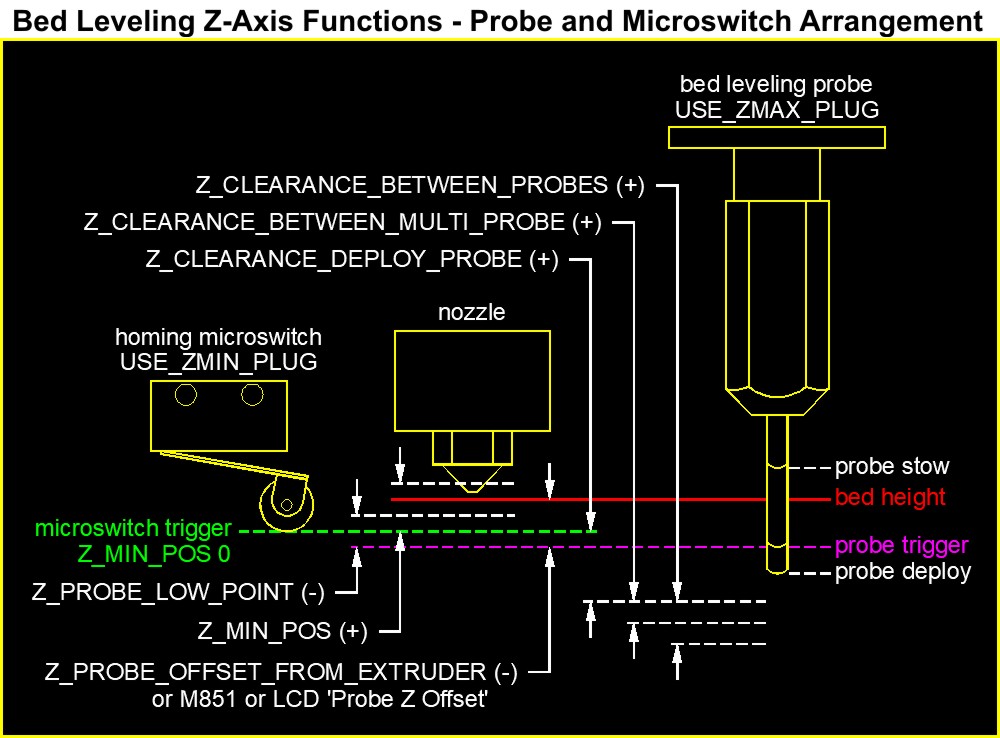
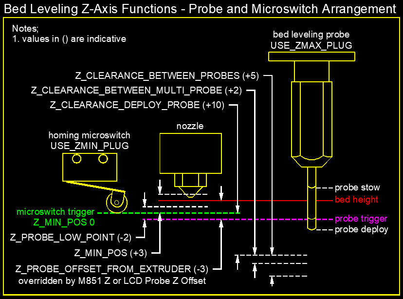
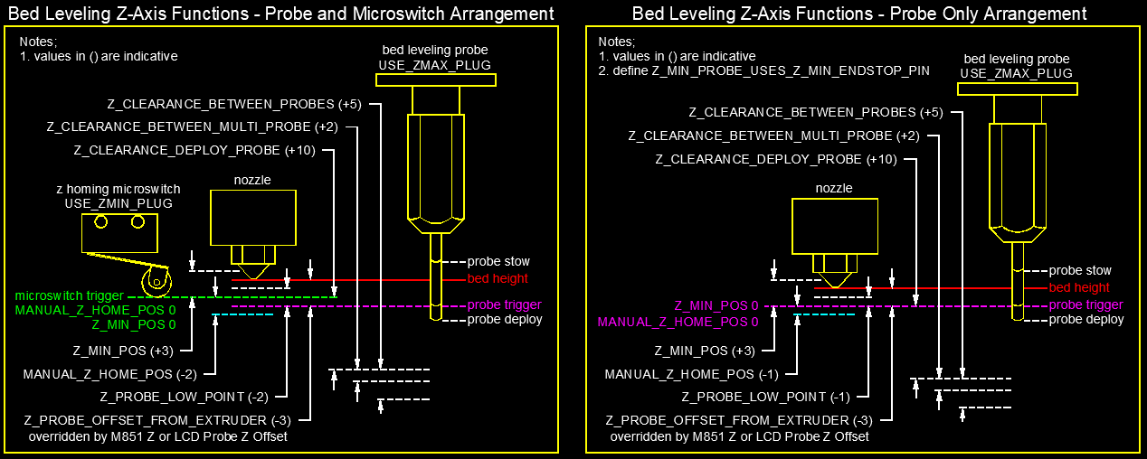
I have recently installed Marlin Bugfix 2.0. I was confused with the plethora of the z-axis functions and so I thought a picture might say a 1000 words. With input from the Rigidbot Community I have made a sketch to make sense of the important functions. We would greatly appreciate any feedback/suggestions on the drawing and accompanying text which follows or where to find a better explanation;
To ensure a relatively failsafe implementation of a probe for bed leveling it is recommended to use it in conjunction with a mechanical microswitch. The microswitch acts as a homing endstop and dependable reference point for the probe.
The microswitch is ignored during bed leveling, however, if a probing fails to trigger it is stopped by the Z_PROBE_LOW_POINT function variable and will retry up to four times before aborting the bed leveling.
The Z_PROBE_LOW_POINT variable needs to account for any dips in the bed but not low enough that it crashes into the nozzle. The probe probes down from the nominal bed height (at homing) to Z_PROBE_LOW_POINT - Z_PROBE_OFFSET_FROM EXTRUDER (both are negative values).
Once the leveling is done the lowest point below the nominal bed height needs to be calculated and accounted for in Z_MIN_POS. Z_MIN_POS is the sum of the distances between z-min set by the microswitch and the nominal bed height during homing plus the height of the lowest dip in your bed matrix.
Addendum; The probe and microswitch have separate roles but are tied together in the background. I really like the Z_MIN_POS function as I believe it allows one to place the z-axis microswitch in an arbitrary position (other than at first layer printing level) and to go beyond it to allow for dips or a tilt in your bed. It would be perfect if, after a G29, the figures that make up Z_MIN_POS could be calculated and displayed so they can be pasted as a precise Z_MIN_POS value.

 Virtualight
on 28 Aug 2019
Virtualight
on 28 Aug 2019
That's a GOOD diagram! I'm book marking that post.
Roxy-3D
on 28 Aug 2019
@Roxy-3D - greatly appreciate your positive feedback - especially given your role in the Marlin Dev team and in-depth knowledge of UBL.
The back end code is not my forte so if you can kindly take a moment to offer some CRITICAL feedback on the diagram and how we might improve/add to it I will gladly amend it. In particular if you can validate the role I have put forward for Z_MIN_POS in this arrangement and comment on the arbitrary position of the microswitch, I would be most grateful.
Virtualight
on 28 Aug 2019
I think Z_MIN_POS should be lower than the micro-switch trigger position. The reason being, the nozzle needs to be able to be lowered to the point the micro-switch triggers.
It would be good to merge this diagram into the documentation side of the repository.
Roxy-3D
on 28 Aug 2019
My suggestion is to color code each dotted line and arrow pair to the text so its easier to track. Some of it gets kinda crowded.
 InsanityAutomation
on 28 Aug 2019
InsanityAutomation
on 28 Aug 2019
@Roxy-3D - thanks for the feedback - The Z-MIN_POS is in fact lower than the microswitch. It is shown above the nozzle to make a point that it will allow the first layer to print into a dip in the build plate. Don't worry - it is also screwing with my head - and I drew it :-)
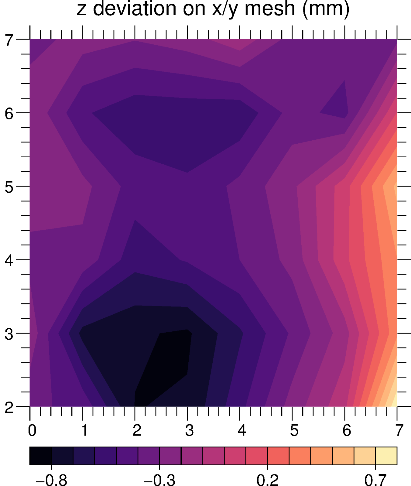
I started this sketch after 3 days of frustration with bed leveling. To put this into context - I have a large wooden bed that is far from flat (see visualisation attached) so it is a good test ground for bed leveling to say the least. The sketch has already helped me and maybe it will help others (noting frustration in above posts).
Unfortunately, I do not feel confident that the drawing or text is anywhere near correct and that is why I am posting here. I know nothing about the underlying code and marvel at those who develop it. I am sketching blindly and need some guidance/collaborators to help visualise how to fix and improve on it. Moreover, this sketch only covers one scenario which happens to be the scenario I have on my Double H-Bot. I can imagine a series of similar drawings for other setups.
@InsanityAutomation - good suggestion regarding colour coding and I agree it is a bit cluttered. I also agree the drawing can definitely be improved on but first I would like confirmation that it is representative of the underlying code.
@edwilliams16 who is also collaborating on the diagram and accompanying explanatory text has asked how the soft endstops fit into the equation. Also currently we don't know for sure if say you have your microswitch at bed level (first layer height) and Z-MIN_POS set to 0, will it print into a dip in your bed i.e. is the microswitch at ZMIN ignored? Can someone please help answer these questions?
Virtualight
on 28 Aug 2019
Attempting to clarify @Virtualight 's diagram, I need to understand more than I do about the interactions between bed-leveling, end-stops and the various configuration settings. Thee's a lot of questions, so if you answer any, it would help if you quote my question so we are less likely to disappear down rabbit-holes of misunderstanding. In addition, I make a bunch of statements that I believe to be true, but may not be. Please feel free to clarify/correct them too! I'm likely assume your answers apply to all leveling schemes unless you say otherwise. With your help, perhaps we can come up with some additional documentation that will help the community.
Bed-leveling, end-stops and z configuration.
Let's assume a cartesian printer with a microswitch and a BL-touch on the z-axis. Assume the slicer generates G-code putting the bottom of the model at z=0. We assume our bed-leveling setup generates a height map of our (in general not flat) bed, relative to some reference point R. During printing, the z-information from the G-code is "bed-corrected" by the height map as a function of x/y. A motion in the x/y plane at z=0 thus tracks the nozzle along the bed surface, following its dips and bumps. For this to happen, the point R has to be at z=0 in the machines coordinate system. Homing in z is designed to achieve this.
Homing z.
We can use either the probe or the microswitch as our homing reference (what configuration variable(s) controls this?). In either case, the carriage is lowered (or the bed raised) until the device triggers.
For a probe, at the trigger point the current z-coordinate is set to Z_HOME - Z_PROBE_OFFSET. If we home down over the point R (Z_SAFE_HOMING defines R to be at the surface on the center of the bed), then z=0 at R is achieved by having Z_HOME=0. The internal variable Z_HOME defaults to Z_MIN_POS, but can be over-ridden by setting MANUAL_Z_HOME_POS.
For a micro-switch, for a flat level bed, the standard configuration is to adjust it so it triggers when the nozzle reaches bed height. This means Z_HOME = 0 - derived from the setting Z_MIN_POS = 0.
In the general case, where the microswitch triggers at some point above (or below) our uneven bed, we need to decide what values to set Z_MIN_POS and/or MANUAL_Z_HOME_POS. In this situation we will still need to set Z_PROBE_OFFSET so that when we probe to get our bed leveling map, the heights are referenced to the nozzle not to the trigger point of the probe.
If we temporarily ignore the function of the microswitch as an end stop, it would appear we can freely choose Z_MIN_POS and/or MANUAL_Z_HOME. Wherever the z=0 coordinate plane ends up, the probing for the bed-leveling will use this as the reference for the bed height. Moving the coordinate plane z=0 up or down will make a corresponding constant decrease or increase in the bed height table such that the "corrected" z of a z=0 line generated by the slicer will still run the nozzle along the surface of the bed.
However, the microswitch can act as an end-stop at its z location. In addition, we may have a software end stop if MIN_SOFTWARE_ENDSTOP is defined. The software end stop is located at Z_MIN_POS
Most of my confusion is related to when these are enabled a) during G29 probing and b) printing.
For a flat level bed coplanar with the microswitch end-stop everything is happy when Z_MIN_POS=0. The hardware end-stop and software stop (if enabled) all trigger as the nozzle touches the bed, preventing damage from bad commands that try to push the nozzle through the bed yet allowing printing on the surface.
What about our bumpy bed? If we homed using the probe and set Z_MIN_POS=0, our z=0 reference surface runs through the point where the homing probe triggered on the bed. If we move to probe a another point on the bed, we need to assure
(1) No end-stops trigger before the probe is complete.
(2) If the probe erroneously fails to trigger, it isn't damaged by driving it into the bed.
Case 1 should not be a problem as long as |Z_PROBE_OFFSET| exceeds the max variation of the bed height. Case 2 we deal with by setting Z_PROBE_LOW_POINT which is the lowest z coordinate the probe trigger point will be allowed to probe. This should be something like the maximum distance the probe can retract less the variation in bed height. The default -2 is probably good.
In the case of homing with a microswitch, we can avoid the soft end-stops either by temporarily disabling them or by a suitable choice of Z_MIN_POS and perhaps MANUAL_Z_HOME (What choice?) How do we handle a microswitch end-stop above the bed? Is there a setting to temporarily ignore them?
During printing, are the end-stops enabled - at least during the first few layers where we are filling in the hollows on the bed up to the z=0 plane?
Is the soft end-stop triggered by the "bed-corrected" z or by the nominal z from the slicer?
Note that if the soft end-stop is enabled and we use the corrected z, it will need to be located at or below the lowest point of the bed - in which case we need to arrange for this somehow. (With nominal z, we can just set the soft end-stop at z=0)
In the case of the microswitch end-stop, if it is enabled when printing the layers between the bed and its trigger point, we won't be able to print them. How do we get around this without disabling them entirely?
 edwilliams16
on 29 Aug 2019
edwilliams16
on 29 Aug 2019
Updated sketch based on feedback - hopefully a little clearer to read.
Virtualight
on 29 Aug 2019
Z_PROBE_OFFSET_FROM_EXTRUDER is from the nozzle tip to the probe trigger point - and the nozzle tip line is a bit off.
edwilliams16
on 29 Aug 2019
Homing z.
We can use either the probe or the microswitch as our homing reference (what configuration variable(s) controls this?).
@edwilliams16 - I believe that whatever is plugged into USE_ZMIN_PLUG will be the homing reference. If you probe is plugged into this then uncomment the function Z_MIN_PROBE_USES_Z_MIN_ENDSTOP_PIN
Virtualight
on 29 Aug 2019
Z_PROBE_OFFSET_FROM_EXTRUDER is from the nozzle tip to the probe trigger point - and the nozzle tip line is a bit off.
@edwilliams16 - when I set Z_PROBE_OFFSET_FROM_EXTRUDER I lower my probe to printing height not bed level... The position of the nozzle in the drawing is intentional but can change if I am mistaken.
Virtualight
on 29 Aug 2019
@edwilliams16 - great questions - looking forward to getting to the bottom of them all - no pun intended!
Virtualight
on 29 Aug 2019
@Virtualight I was going by the youtube instructions in https://www.youtube.com/watch?v=y_1Kg45APko
Z-Offset Instructions:
- Home 3D printer
- M851 Z0 - Reset Z0Offset
- M500 - Store setting to eeprom
- M501 - Set active parameters
- M503 - Display Active Parameters
- G28 Z - Home Z Axis
- G1 F60 Z0 - Move nozzle to true 0 offset
- M211 S0 - Switch off soft endstops
- Move nozzle towards bed slowly until the paper can barely move
- Take note of the Z on the printer display (take that number and add the measurment of the calibration sheet or device used)
- M851 Z X.XX (X.XX being your z offset achieved)
- M211 S1 - Enable Soft Endstops
- M500 - Save settings to Eeprom
- M501 - Set Active Parameters
- M503 - display current settings
This sets it the way I described. However when I level my printer by hand I don't put in the offset for thickness of my piece of paper which is about 0.1 mm - so you have a point. But the Marlin definition is "These offsets specify the distance from the tip of the nozzle to the probe — or more precisely, to the point at which the probe triggers." http://marlinfw.org/docs/configuration/configuration.html#probe-offsets- So we should go with that as a matter of definition.
edwilliams16
on 29 Aug 2019
@edwilliams16 - yes I have seen same videos, however, as you suggest setting you nozzle height to be touching the bed doesn't seem practical unless it is subsequently compensated for in the slicing software/gcode. By default all the slicers I have used start the first layer height at ZMIN...
Virtualight
on 29 Aug 2019
Then I suggest the drawing should conform to the Marlin definition, but the accompanying text should make your point that when you actually measure it, you might want to allow for a typical printing height - eg the thickness of a piece of paper for a standard nozzle.
edwilliams16
on 29 Aug 2019
Homing z.
We can use either the probe or the microswitch as our homing reference (what configuration variable(s) controls this?).@edwilliams16 - I believe that whatever is plugged into USE_ZMIN_PLUG will be the homing reference. If you probe is plugged into this then uncomment the function Z_MIN_PROBE_USES_Z_MIN_ENDSTOP_PIN
I definitely believe that. But searching the source, I'm at a loss to find where Z_MIN_ENDSTOP actually gets used! Probably hidden inside some ingenious macro. I understand why this code is written more in preprocessor than C, but it sure makes harder (for me) to understand it. Gripe off...
edwilliams16
on 29 Aug 2019
Ed, try installing AstroGrep. It helps a lot when trying to locate where different symbols are used within the Marlin firmware. http://astrogrep.sourceforge.net/download/
Here is what it shows me for Z_MIN_ENDSTOP
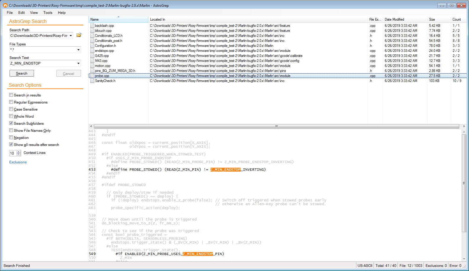
Also... You can configure it to use what ever your favorite editor is. You double click on any highlighted line, and your editor pops up with that section of the code in view.
Roxy-3D
on 29 Aug 2019
I have to disagree with @Roxy-3D here, the global search built into VSCode and PlatformIO handles this much better in the integrated IDE with syntax highlighting and active code block shadowing.
But my advise is try both and decide for yourself which you prefer!
InsanityAutomation
on 29 Aug 2019
my mistake - I was actually searching for USE_ZMIN_PLUG @Virtualight was referring to.
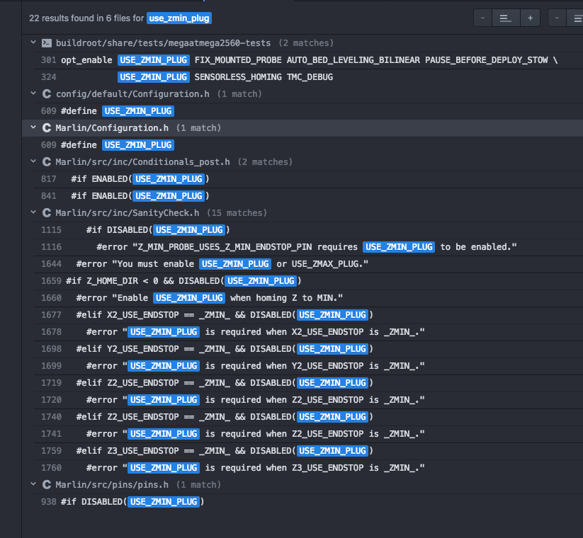
I just installed Atom/PlatformIO since that was the recommended setup for 32-bit Marlin - when I worked for a living I just used emacs. None of the above results seem to lead to code operating the endstops.
edwilliams16
on 29 Aug 2019
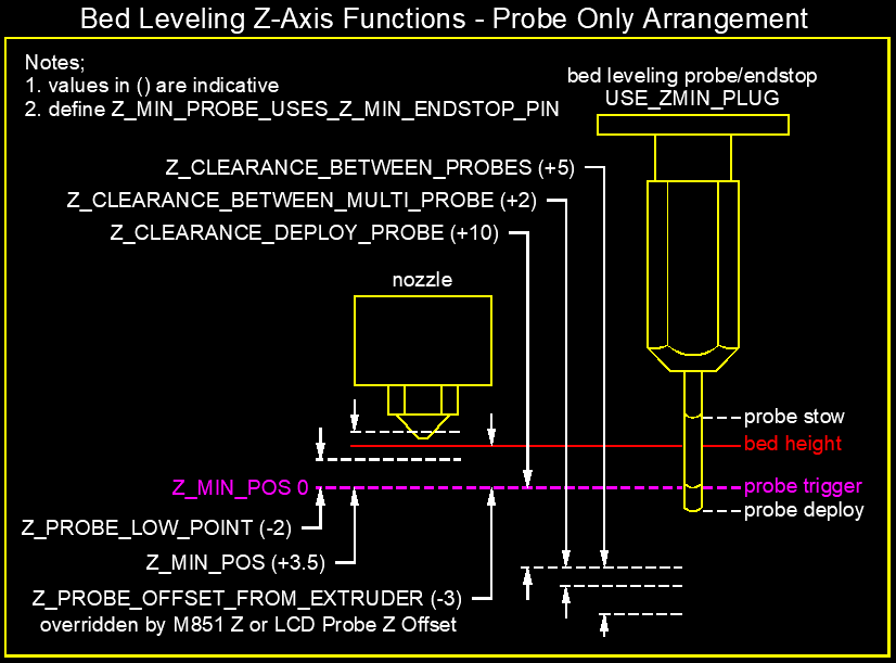
New sketches showing two arrangements with indicative variable values added.
Virtualight
on 29 Aug 2019
This sets it the way I described. However when I level my printer by hand I don't put in the offset for thickness of my piece of paper which is about 0.1 mm - so you have a point. But the Marlin definition is "These offsets specify the distance from the tip of the nozzle to the probe — or more precisely, to the point at which the probe triggers." http://marlinfw.org/docs/configuration/configuration.html#probe-offsets- So we should go with that as a matter of definition.
In my opinion the Marlin documentation needs to reflect the practical, logical and community accepted implementation of Z_PROBE_OFFSET_FROM_EXTRUDER i.e. bed height is set at first layer printing height. Note that the function says OFFSET_FROM_EXTRUDER not NOZZLE. Here is a suggested amendment to the Marlin 'Probe Offsets' documentation for discussion;
"The X and Y offsets specify the distance from the tip of the nozzle to the probe respectively. The Z offset specifies the distance from the first layer print height to the probe trigger point and should be specified precisely. The Z offset can be overridden with M851 Z or LCD Probe Z Offset. The M851 offsets are saved to EEPROM with M500. The X, Y and Z offsets are specified as decimal integers (millimetres)."
Virtualight
on 29 Aug 2019
@virtualight I was skeptical of your statement "By default all the slicers I have used start the first layer height at ZMIN"
I set up a print of a calibration cube using Simplify3D (which you use). I set the layer height to 0.2 mm and first layer to 90%. I exported the G-code and took a look.
The z move prior to printing the first line was "G1 Z0.18". So Simplify3d prints assuming the bed lies at z=0.
edwilliams16
on 29 Aug 2019
And Z_MIN_POS isnt the only thing that can define the home position. If you set MANUAL_Z_HOME_POS then Z_MIN_POS becomes the limit for tool change offset application, and manual jogging.
InsanityAutomation
on 29 Aug 2019
The z move prior to printing the first line was "G1 Z0.18". So Simplify3d prints assuming the bed lies at z=0.
Slic3r (which I use) also assumes the bed is at 0.00 mm.
Roxy-3D
on 29 Aug 2019
@edwilliams16 and @Roxy-3D - I appreciate you both looking into my comment further which was based purely on external observation. I guess I never noticed the 0.18mm... I stand corrected and will update my sketches.
Virtualight
on 29 Aug 2019
@Roxy-3D and other experts on the code. I'm really hoping you can critique my analyses in my long post above and answer my questions. Then we can come up with diagrams, documentation, examples that will save a lot of people a lot of time blundering around to find a working solution to their situation.
For immediate context @Virtualight wants a setup with a BLTouch to probe the bed for bed-leveling- but since it has been unreliable, he wants to use a microswitch as a safety back-stop limit switch and z homing device. It's not clear we've found the right configuration yet. In his generic diagram, it's not specified how the microswitch is mounted - but my current opinion is this can only be made to work with the microswitch on the extruder carriage, set to trigger just before the the nozzle touches the bed. My questions above are questions of program logic which would equally apply to a frame-mounted microswitch.
edwilliams16
on 29 Aug 2019
Here are the updated sketches with the nozzle at bed height. Also an amended amendment suggestion for the Marlin Probe Offsets documentation;
"The X and Y offsets specify the distance from the tip of the nozzle to the probe respectively. The Z offset specifies the distance from the tip of the nozzle to the probe trigger point and should be specified precisely. The Z offset can be overridden with M851 Z or LCD 'Probe Z Offset. The M851 offsets are saved to EEPROM with M500. Offsets are specified as decimal integers (millimetres)."


Virtualight
on 29 Aug 2019
And Z_MIN_POS isnt the only thing that can define the home position. If you set MANUAL_Z_HOME_POS then Z_MIN_POS becomes the limit for tool change offset application, and manual jogging.
@InsanityAutomation - thanks for the clarification for MANUAL_Z_HOME_POS - I will try to incorporate into the sketch
Virtualight
on 29 Aug 2019
It's not clear we've found the right configuration yet. In his generic diagram, it's not specified how the microswitch is mounted - but my current opinion is this can only be made to work with the microswitch on the extruder carriage, set to trigger just before the the nozzle touches the bed. My questions above are questions of program logic which would equally apply to a frame-mounted microswitch.
The big problem you are going to run into doing this is the BL-Touch pin doesn't deploy very far out. The BL-Touch pin rests (when stowed) only about 1.5mm above the nozzle. And any curling of the print edges can catch the BL-Touch pin.
So trying to position a micro-switch to trigger just before the nozzle crashes into the bed is going to take a fair amount of mechanical precision. I think this is going to be more effort than just resolving
the BL-Touch reliability problems.
Roxy-3D
on 29 Aug 2019
Offsets are specified as decimal integers (millimetres).
z offset is decimal millimeters. x/y are integer.
edwilliams16
on 29 Aug 2019
@Roxy-3D
The big problem you are going to run into doing this is the BL-Touch pin doesn't deploy very far out. The BL-Touch pin rests (when stowed) only about 1.5mm above the nozzle. And any curling of the print edges can catch the BL-Touch pin.
This seems like a BLTouch problem independent of Peter's particular configuration. But if the stowed pin is 1.5 mm above the nozzle and the print curls up enough to hit it, you'd already be in trouble as the nozzle will hit the print at some point. Or is it that is is fragile and doesn't take kindly to being sideswiped by the print? If that's the case maybe the mount should have some protective collar.
Given his proven engineering skills, I'm pretty sure Peter could come up with some adjustable mount that would allow tweaking the microswitch to bed clearance, if that became necessary.
edwilliams16
on 29 Aug 2019
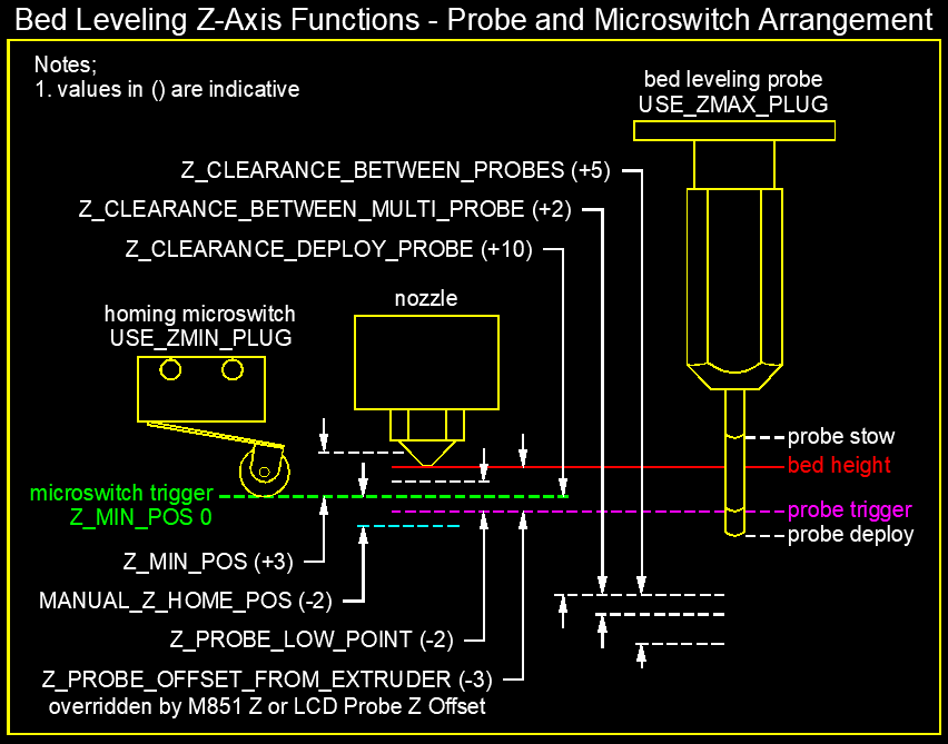
@InsanityAutomation - I have added an arbitrary MANUAL_Z_HOME_POS to the sketch. Let me know if it makes sense.
Virtualight
on 29 Aug 2019
@Roxy-3D - I have to agree with @edwilliams16 - the nozzle is the low point which will tend to guard the stowed BLTouch probe. The Antclabs recommended height of the stowed probe is 2mm above the nozzle. I do like the idea of a protective collar @edwilliams16 .

Virtualight
on 29 Aug 2019
Z_MIN_POS and MANUAL_Z_HOME_POS are off in their behavior here. MANUAL_Z_HOME_POS is the point where the microswitch triggers. Z_MIN_POS is the travel low limit. If MANUAL_Z_HOME_POS is not defined, it is set to match Z_MIN_POS Bed is assumed to be wherever 0 is.
This is useful should you say put a microswitch with a lever arm on the side of the z beam so the gantry can come down and keep going right past it. It could be +5, or -5. Its simply a fixed known position.
For the purpose of this graphic, lets say youre microswitch triggers at -2, so Z_MIN_POS could be 0 to prevent any moves below the bed typically, with safe homing forcing you to home off the plate. Then MANUAL_Z_HOME_POS is set to -2 so when it homes and sees the switch, it sets the position to -2. You cant get back below 0 once youve jogged up with this.
You could also set Z_MIN_POS to -5 here, and it would have no purpose but to stop you from pushing TOO far into the bed with the soft endstops.
InsanityAutomation
on 30 Aug 2019
For the purpose of this graphic, lets say your microswitch triggers at -2, so Z_MIN_POS could be 0 to prevent any moves below the bed typically, with safe homing forcing you to home off the plate. Then MANUAL_Z_HOME_POS is set to -2 so when it homes and sees the switch, it sets the position to -2. You cant get back below 0 once you've jogged up with this.
Thanks. I can see how this works if the bed is flat and level at z=0, but what happens if it has dips below z=0 and we are using bed leveling? Does the soft stop at z=0 prevent printing there, or does the code avoid this problem in some way (like by testing the slicer z rather than the bed-corrected z against the z=0 soft stop limit)?
edwilliams16
on 30 Aug 2019
The corrected position is used for the softlimits, and Z_PROBE_LOW_POINT sets the lowest point below Z_MIN_POS that the probe can go
InsanityAutomation
on 30 Aug 2019
This is useful should you say put a microswitch with a lever arm on the side of the z beam so the gantry can come down and keep going right past it. It could be +5, or -5. Its simply a fixed known position.
@InsanityAutomation - good point - the action of a microswitch that can be bypassed by a positive Z_MIN_POS needs to be considered. One or two mm over is not going to hurt your average lever action microswitch in the orientation shown in my drawing but 5mm may well bend or break it.
What I like about Z_MIN_POS, which I have said before, is that it allows you to put the microswitch homing endstop at an arbitrary position below bed height. The position can then be either measured (with a ruler) to find its position or preferably derived by the bed leveling procedure which would also, and importantly, take into account any negative values in the mesh which would need to be accounted for in Z_MIN_POS.
Virtualight
on 30 Aug 2019
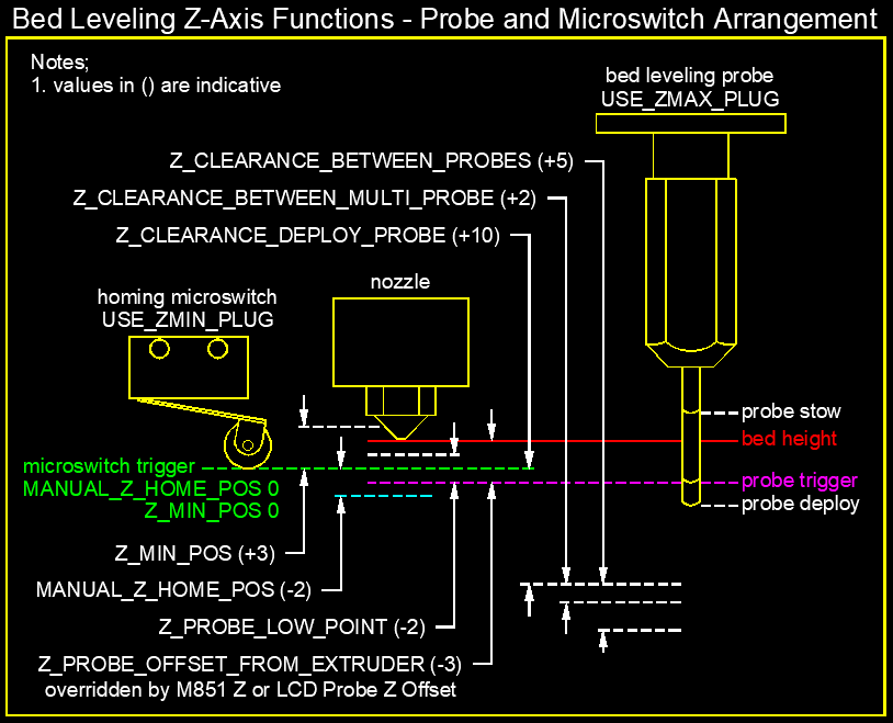
@InsanityAutomation - thanks for your most excellent feedback - I have added MANUAL_Z_HOME_POS 0 to the diagram.
Virtualight
on 30 Aug 2019
The corrected position is used for the softlimits, and Z_PROBE_LOW_POINT sets the lowest point below Z_MIN_POS that the probe can go.
@InsanityAutomation
Z_PROBE_LOW_POINT allows for probing below the soft limit - but my question was about printing below them.
If Z_POS_MIN=0 say, and the probed bed height is say -0.7mm at some x/y, suppose we try to print an 0.2 mm layer there. The slicer code says G1 Z0.2. The bed-correction translates that to G1 Z-0.5 - does the soft limit stop the move at G1 Z0 or not?
edwilliams16
on 30 Aug 2019
@InsanityAutomation - So I think this confirms that during printing if Z_MIN_POS = 0 that the soft endstops (if enabled) will not allow you to print into a dip in your bed. I think this will be a revelation to many out there who would not think to change Z_MIN_POS...
Virtualight
on 30 Aug 2019
@edwilliams16 - Ha Ha - nice to see you thinking what I am thinking 4,369 miles north of here.
Virtualight
on 30 Aug 2019
@edwilliams16 If you look at at the arrangement where there is no microswitch and only the probe you absolutely need to enable Z_MIN_POS or disable MIN_SOFTWARE_ENDSTOP_Z which would leave you unprotected. This is my exact experience when I had this arrangement.
Virtualight
on 30 Aug 2019
@Virtualight
If it's really true that you can't print below Z_MIN_POS (when demanded by the bed correction) and you use only the probe, the best you can do, IMO, is to probe the bed, look at the correction map and find the lowest point, then adjust Z_MIN_POS so that z=0 lies at the lowest point of the bed. (and reprobe or adjust the map) I didn't like that potential solution several days ago when we first started thinking about this, as everywhere else on the bed the nozzle can crash down into the bed down to z=0, making mm size dents in your MDF. I felt that your idea of mounting a switch on the extruder was a potential solution if it triggered a hair above the bed.
edwilliams16
on 30 Aug 2019
My gut feeling is that we are getting close with the diagrams (see below). Maybe I should also to do one for a proximity sensor which will cover the most common bed sensing probing arrangements. I think we have most of the information for some text to accompany them. Thoughts?
Virtualight
on 30 Aug 2019
@edwilliams16 It will never crash into the bed if it is following the mesh. The only way I can see that happening is if the microswitch reference point moves or fails for whatever reason.
Virtualight
on 30 Aug 2019
@Virtualight It can't crash into the bed if the microswitch acts as an endstop and it triggers just below the nozzle. Whether a probe-only solution is possible I think is still up in the air. In the scenario I had rejected (using the low point of the bed as a soft stop) any G1 Z0 anywhere else on the bed would result in a crash.
edwilliams16
on 30 Aug 2019
I might be able to answer some of my questions about the interaction of bed-leveling and endstops experimentally, despite having a flat bed and no probe. It appears I might be able to make a gross synthetic mesh using M421 and move my soft end-stop well above my bed with Z_MIN_POS. Then I can try some G1 moves and see what's accessible. Might learn something. Any thoughts?
edwilliams16
on 30 Aug 2019
@edwilliams16 - I agree that having Z_MIN_POS set just below the nozzle is the safest option, however, if your bed has dips that exceed this then you compromise on your first layer. What would be the point of doing a bed level if you flatten off all of you low points...
I agree with your methodology for adjusting Z_MIN_POS so that z=0 lies at the lowest point of the bed. I assume the base point for all of the probing measurements is Z_MIN_POS 0. If so then that is the figure that needs to be put into Z_MIN_POS.
Virtualight
on 30 Aug 2019
I might be able to answer some of my questions about the interaction of bed-leveling and endstops experimentally, despite having a flat bed and no probe. It appears I might be able to make a gross synthetic mesh using M421 and move my soft end-stop well above my bed with Z_MIN_POS. Then I can try some G1 moves and see what's accessible. Might learn something. Any thoughts?
@edwilliams16 - good thinking! We will have proof at last!
Virtualight
on 30 Aug 2019
Keep in mind normally endstops are not on during printing unless you enable them. Z min Po's follows the planner position. Bed leveling modifies that so in theory you can get down to the z probe low point below z min Po's.
InsanityAutomation
on 30 Aug 2019
I agree with your methodology for adjusting Z_MIN_POS so that z=0 lies at the lowest point of the bed. I assume the base point for all of the probing measurements is Z_MIN_POS 0. If so then that is the figure that needs to be put into Z_MIN_POS.
I think I would try this way:
- use Z_SAFE_HOMING so you home over a fixed point over the middle of the bed
- start with Z_MIN_POS 0 MANUAL_Z_HOME unset
- home z and generate a mesh. The mesh entries will be z heights relative to the trigger point of your microswitch when it homed. You need Z_PROBE_LOW_POINT -2 say, so the probing will go up to 2 mm below your z=0 homing plane.
- Inspect the mesh and find the lowest point zmeshmin (we will necessarily have zmeshmin < 0)
- set MANUAL_Z_HOME -zmeshmin This should move z=0 to the lowest point of your mesh. We retain Z_MIN_POS 0 which locates the soft endstop at the low point at z=0.
- edit your mesh by subtracting -zmeshmin from each point (How to do this seems to vary between schemes) This will make all the mesh entries >=0
- check by homing again and making a second mesh. It should agree with your above modified one, with minimum value 0 and the rest positive.
- Try a G26 mesh validation pattern
edwilliams16
on 30 Aug 2019
Keep in mind normally endstops are not on during printing unless you enable them. Z min Po's follows the planner position. Bed leveling modifies that so in theory you can get down to the z probe low point below z min Po's.
@InsanityAutomation - I don't know if that answers the question or not. Simple yes or no question - if after performing a G29 there are dips in your bed, can you print into them if Z-MIN_POS =0?
Virtualight
on 30 Aug 2019
@edwilliams16 - I was with you until point 5. Wasn't sure what would be achieved that making the low point the value for Z_MIN_POS wouldn't also achieve. Maybe I just don't understand, however, but it seems overly complex...
Virtualight
on 30 Aug 2019
Keep in mind normally endstops are not on during printing unless you enable them. Z min Po's follows the planner position. Bed leveling modifies that so in theory you can get down to the z probe low point below z min Po's.
@InsanityAutomation - I don't know if that answers the question or not. Simple yes or no question - if after performing a G29 there are dips in your bed, can you print into them if Z-MIN_POS =0?
Yes you can
InsanityAutomation
on 30 Aug 2019
Keep in mind normally endstops are not on during printing unless you enable them. Z min Po's follows the planner position. Bed leveling modifies that so in theory you can get down to the z probe low point below z min Po's.
@InsanityAutomation - I don't know if that answers the question or not. Simple yes or no question - if after performing a G29 there are dips in your bed, can you print into them if Z-MIN_POS =0?
Yes you can
OK so z-min microswitch is ignored during printing. I am confused. I thought Z_MIN_POS set the Z soft endstop? So what is the point of having Z_MIN_POS if it is ignored? I thought that Z_MIN_POS would act for the microswitch like Z_PROBE_LOW_POINT does for the probe?
Virtualight
on 30 Aug 2019
@Virtualight I think it works this way. We have two tasks: (1) define the z coordinate so that z=0 is at the low point of the mesh (2) set the soft end stop at z=0
The only way to achieve (2) is by Z_POS_MIN 0 because it's the variable that describes the machine limit.
BUT, the default side effect of that is it also sets the home (z=0) location to where your switch triggers, but we don't want that. However, we can over-ride it by setting MANUAL_Z_HOME This sets the z-coordinate of the trigger point to MANUAL_Z_HOME. By setting it to -zmeshmin the z=0 surface will lie (-zmeshmin) below it, precisely through the low point of the mesh.
We can only do two tasks with one number if they are tied together - in the classic case of a level bed and a microswitch that triggers at bed height they are. In our case they aren't tied together (because our microswitch doesn't trigger at the low point of the bed) so it's logically impossible to do them both with a single assignment.
edwilliams16
on 30 Aug 2019
Have been doing some experimenting and am currently trying to get my head around why the probe probes down to Z_PROBE_LOW_POINT - Z_PROBE_OFFSET_FROM EXTRUDER. This requires one to know the Z_PROBE_OFFSET_FROM EXTRUDER value before setting Z_PROBE_LOW_POINT. If Z_PROBE_LOW_POINT is smaller than Z_PROBE_OFFSET_FROM EXTRUDER then the probe doesn't trigger. It also means if the value of Z_PROBE_OFFSET_FROM EXTRUDER is changed then you have to alter the Z_PROBE_LOW_POINT by the same amount. Doesn't seem logical...
Virtualight
on 30 Aug 2019
Here is what the diagram looks like using the current Z_PROBE_LOW_POINT calculation. It says what it does but seems an impractical method of applying what should really be another offset.

Virtualight
on 30 Aug 2019
Can I suggest we change #define Z_PROBE_LOW_POINT from "Farthest" to 'Extra' distance below the trigger-point to go before stopping?

Virtualight
on 30 Aug 2019
I am now doing some experimenting on the printer myself and Z_PROBE_LOW_POINT should be a positive value not a negative value as in my previous diagram.
I have no idea what is going on there, then. You are not the first to complain about the definition:
see https://github.com/MarlinFirmware/Marlin/issues/11235
but as we discussed elsewhere, the probe code says to probe down to z = Z_PROBE_LOW_POINT - Z_PROBE_OFFSET. This would move the probe trigger point down to z=Z_PROBE_LOW_POINT since the moves are referenced to the nozzle.
However we may have screwed up where home is (ie where z=0 is), the sign is clear, to probe lower you need to make Z_PROBE_LOW_POINT smaller (more negative), so if it works the other way, I have absolutely no idea where a sign change could have slipped in.
In probe.cpp we have
const float z_probe_low_point = TEST(axis_known_position, Z_AXIS) ? -zprobe_zoffset + Z_PROBE_LOW_POINT : -10.0;
...
do_probe_move(z_probe_low_point, MMM_TO_MMS(Z_PROBE_SPEED_SLOW)
I think the correct definition should be:
"Lowest z to which the probe trigger point is lowered when probing." - but this needs amplification in the situation where we have messed with either Z_POS_MIN or MANUAL_Z_HOME as these move z=0 away from the homing trigger point.
I still need to get my printer on 2.0 before I can experiment - got busy today.
edwilliams16
on 30 Aug 2019
The soft-endstops are applied before the leveling correction. Printing in a valley does not require a negative z-coordinate from the view the soft-endstops look at it..
The hard-endstops come when they come and are activated..
Z-Probes can't be hard endstops - only home-switches. They are active only when deployed (active). Else you could not print low.
 AnHardt
on 30 Aug 2019
AnHardt
on 30 Aug 2019
The soft-endstops are applied before the leveling correction. Printing in a valley does not require a negative z-coordinate from the view the soft-endstops look at it..
Thanks. I should have just dismissed the obviously incorrect answers to my question of two days ago "Is the soft end-stop triggered by the 'bed-corrected' z or by the nominal z from the slicer?" , rather wasting time thinking up inadequate work-arounds to what would be a bug obvious to any developer.
The hard-endstops come when they come and are activated..
I could use a little more clarity on this one. I don't see a G-code to turn them on or off. If I use a microswitch like device to provide a home position, do I have the option to ignore it as a stop while printing? IOW only use a probe for generating a bed-leveling map and not for homing, in a quest for greater reliability.
edwilliams16
on 30 Aug 2019
I don't see a G-code to turn them on or off.
M120/M121 turn physical endstops on/off. They default to only being on when homing, unless you set ENDSTOPS_ALWAYS_ON_DEFAULT in Configuration_adv.h.
 ManuelMcLure
on 30 Aug 2019
ManuelMcLure
on 30 Aug 2019
Thank you, I'm not sure how I missed that. That's very helpful.
edwilliams16
on 30 Aug 2019
Can I suggest we change #define Z_PROBE_LOW_POINT from "Farthest" to 'Extra' distance below the trigger-point to go before stopping?
To clarify my statement above. The current "farthest" definition correctly defines Z_PROBE_LOW_POINT = Z_PROBE_LOW_POINT - Z_PROBE_OFFSET_FROM_EXTRUDER. What I am suggesting is that the definition should be changed to, "'Extra' distance below the trigger-point to go before stopping?" including adding the background logic, Z_PROBE_LOW_POINT + Z_PROBE_OFFSET_FROM EXTRUDER, otherwise Z_PROBE_LOW_POINT will need to be manually changed every time the Z_PROBE_OFFSET_FROM EXTRUDER is changed.
Virtualight
on 31 Aug 2019
This is just where a good diagram would help parse the definition. It isn't clear from your definition, for instance, that the "distance below" is a negative quantity. (assuming we're actually agreed on this - you can easily test by making it large positive and negative and see what happens when you do a single probe. It's a safe maneuver unless the probe fails to trigger :-( ) It's also not clear from your definition that it is modified by non-zero choice of either Z_MIN_POS or MANUAL_Z_HOME - which is admittedly non-typical, since most will be using the probe to home.
edwilliams16
on 31 Aug 2019
Here's a shot at a figure for the simpler situation with just a probe.

edwilliams16
on 31 Aug 2019
It's a safe maneuver unless the probe fails to trigger
With proper guidance... It is still safe. Do everything to update the firmware and values. But then move the nozzle up 100 mm. Tell it to home, and use your finger to trigger the probe (with the nozzle 75 mm above the bed.)
You can do these experiments without risk to your machine!!!
Roxy-3D
on 31 Aug 2019
@Roxy-3D - when the probe works nine times out of ten and you are working at the intimate bed level it is still risky... That is why a microswitch with soft endstops is IMO an essential backstop.
Virtualight
on 1 Sep 2019
Well... I do understand your point.... But if you have room for a micro-switch, why not just use it?
I get better M48 results with a Probe Leg that kicks down with a micro-switch than with a BL-Touch.
(albeit... Both give plenty good results, so it doesn't really matter for me.)
Roxy-3D
on 1 Sep 2019
I have a microswitch on USE_ZMIN_PLUG and a Probe on USE_ZMAX_PLUG. After a successful bed leveling and save I went about measuring the Z_PROBE_OFFSET_FROM_EXTRUDER using the following method;
- Disabling the soft endstops
- Deploying the probe
- Raising z-axis 0.1mm at a time until it triggered the probe and noting down the height on my LCD.
- Raising the z-axis until it was at nozzle height and noting down the height on my LCD.
- The difference is = Z_PROBE_OFFSET_FROM_EXTRUDER
- I entered this using M851 Z-2.8 and saved it to EEPROM
- I enabled soft endstops
Turns out Z_PROBE_OFFSET_FROM_EXTRUDER is completely ignored as far as I can tell for my arrangement. The print height was at 4.6mm above the bed. The homing position of the nozzle is around 3mm from bed height as is the probe trigger point coincidentally. Z_MIN_POS is set to zero but any value put in here has no effect. The only way I could bring the nozzle down to bed height without disabling soft endstops was to make the MANUAL_Z_HOME_POS 4.6.
Issue #13152 may also give some insight to what I am experiencing.
Virtualight
on 1 Sep 2019
Well... I do understand your point.... But if you have room for a micro-switch, why not just use it?
I get better M48 results with a Probe Leg that kicks down with a micro-switch than with a BL-Touch.
(albeit... Both give plenty good results, so it doesn't really matter for me.)
@Roxy-3D - I do have a microswitch and a BLTouch in my current setup. A microswitch that kicks down down sounds like a good option though because having both requires a workaround with Marlin Bugfix 2.0 as it currently stands... In my opinion the code, for the microswitch plus BLTouch arrangement requires some fixing before any helpful diagram can be produced.
In retrospect maybe a diagram was actually the best starting point rather than creating the code and then trying to fit a diagram to the code...
Here is my latest diagram which is closer to how I think it should work than how it actually works.

Virtualight
on 1 Sep 2019
The probe code has been in constant flux for the last 18 months. And we have had a lot of changes to the BL-Touch code recently with the v3.0 crisis. It isn't hard to believe that something got broken.
The big problem is these kinds of problems are difficult to debug without the hardware to duplicate the problem. Do you know C? Can you dig in a little bit and figure out what needs to be changed to get your setup working?
Roxy-3D
on 1 Sep 2019
@Virtualight @Roxy-3D
It looks like you generated the bed-leveling mesh BEFORE you measured Z_PROBE_OFFSET_FROM_EXTRUDER. What value did it have while you were leveling?
I would expect that the mesh wouldn't be affected by a later change in its value, so the printing height would be tied to former height. I can see how setting MANUAL_HOME_Z would fix this. Can you reprobe one of your mesh point and see if/how much it changes?
edwilliams16
on 1 Sep 2019
It looks like you generated the bed-leveling mesh BEFORE you measured Z_PROBE_OFFSET_FROM_EXTRUDER. What value did it have while you were leveling?
It is assumed that the user gets the basic setup and configuration of the printer done before trying to bring up any of the bed leveling systems. The user should get Z_PROBE_OFFSET_FROM_EXTRUDER set correctly as part of the homing procedure.
Without any bed leveling system active (or perhaps even built into the firmware), the user should be able to print a small calibration cube at the center of the bed. If this isn't done prior to bringing up the bed leveling system, things get very complicated because the bed leveling system will be trying to compensate for basic configuration values and not just the bed warp.
Roxy-3D
on 1 Sep 2019
@Virtualight If @Roxy-3D is correct and the current setup (without the MANUAL_Z_HOME fix and with bed-leveling off) can't print on your bed, you can likely still salvage your bed-level probe data. It just needs to be offset in z as only its origin is wrong. Save a copy in another slot and use G29 to edit it. That's why I suggested "Can you re-probe one of your mesh point and see if/how much it changes?" above. That would tell you the required offset.
edwilliams16
on 1 Sep 2019
I don't know C or any other programming language. MANUAL_Z_HOME was a work around to get me up and running. I can't fathom why it should matter when you put Z_PROBE_OFFSET_FROM_EXTRUDER in - it's just an offset.
I am concerned now that my attempt at producing a diagram, and all of its revisions in this thread is only going to add to the confusion as it is currently not representative of the code.
Virtualight
on 1 Sep 2019
@Virtualight
I can't fathom why it should matter when you put Z_PROBE_OFFSET_FROM_EXTRUDER in - it's just an offset.
Because it's used when probing the bed, not when printing. You home with the microswitch - that sets the z =0 surface - referenced to the nozzle. You then probe to make a bed-leveling table - each entry is the z height of the point on the bed. For the code to figure this out it needs add Z_PROBE_OFFSET_FROM_EXTRUDER to the z-value at probe trigger. If you had probed manually by touching the nozzle to the bed rather than the probe, no correction would be necessary, but the resulting table would end up the same. If you have the wrong value of Z_PROBE_OFFSET_FROM_EXTRUDER at this point, the table entry is wrong.
Once you start printing, the probe is totally irrelevant. It's not deployed. The printer just consults the table to determine the nozzle offset to follow the bed bumps and dips. In particular, if you tell it a new value of Z_PROBE_OFFSET_FROM_EXTRUDER it has no effect on printing. It uses the table you made earlier. OTOH, if you probe again, you'll get a different result for the table.
edwilliams16
on 1 Sep 2019
@edwilliams16 - thanks for the explanation. I assumed that you could put Z_PROBE_OFFSET_FROM_EXTRUDER at any time and it would use this offset at the time of printing. This IMO is more intuitive as it would save re-leveling every time you, for instance, change a nozzle or the bed height changes for whatever reason.
Anyway I now have a working solution for my situation. I could not have attempted to print on such a large and uneven surface without Bed Leveling so I am very thankful for the hard work that has gone into making this happen! I am also really happy that Marlin now supports 32bit boards!
Happy to finish off the diagram if someone guides me on how to correct it. Time now to do some actual printing!
My level MDF bed with circular test pattern;

Virtualight
on 1 Sep 2019
This IMO is more intuitive as it would save re-leveling every time you for instance change a nozzle or the bed height changes for whatever reason.
If the bed height changed, it wouldn't be intuitive to me to change Z_PROBE_OFFSET_TO_EXTRUDER because that dimension didn't change. If that fixed it, to me it would be a hack.
If you change a nozzle etc. you can either physically tweak your microswitch position correspondingly (what I do with my flat bed, it contacts a machine screw I can dial up and down) or on the software side either change MANUAL_Z_OFFSET or use M206. I personally wouldn't use both - it's complicated enough already. I'd be inclined to get rid of the MANUAL_Z_OFFSET altogether and store the corresponding M206 setting in EEPROM. Then I could change it easily without having to recompile.
But hey it prints!
I'm currently thwarted on installing Marlin 2.0 because my printer's Mac has too old a version of Python - but I'm working on it.
A day's work fixed this, I think. It's a problem with platformio on Mac OSX Sierra and earlier:
https://github.com/MarlinFirmware/Marlin/issues/15123
edwilliams16
on 1 Sep 2019
@edwilliams16 - I agree that changing Z_PROBE_OFFSET_TO_EXTRUDER for a change in bed height would be a hack and to be fair it would probably require a bed re-leveling but changing a nozzle over would be a situation where you might want to change Z_PROBE_OFFSET_TO_EXTRUDER without having to re-level the bed...
Virtualight
on 3 Sep 2019
The idea of
changing Z_PROBE_OFFSET_TO_EXTRUDER for a change in bed height
is not that strange.
Take a aluminium-bed, a inductive sensor and cover the bed with something not conductive - or not.
AnHardt
on 4 Sep 2019
The idea of
changing Z_PROBE_OFFSET_TO_EXTRUDER for a change in bed height
is not that strange.
Take a aluminium-bed, a inductive sensor and cover the bed with something not conductive - or not.
@AnHardt - we are not saying it is uncommon - just that changing Z_PROBE_OFFSET_TO_EXTRUDER to adjust for it would be a hack. In saying that, if I were to add another layer to bed I would most likely re-level.
Virtualight
on 4 Sep 2019
@AnHardt - we are not saying it is uncommon - just that changing Z_PROBE_OFFSET_TO_EXTRUDER to adjust for it would be a hack. In saying that, if I were to add another layer to bed I would most likely re-level.
The change in Z_PROBE_OFFSET_TO_EXTRUDER is real in that case, not a hack.
The probe still triggers on the aluminium level, but the nozzle is clother to the added layer. Re-leveling will still only measure the alu and will not see a difference.
Same effect with a glas cover and a IR-probe.
I do know, that are not the best probes for the new surfaces. But if you know what you do ...
AnHardt
on 4 Sep 2019
@AnHardt - indeed this would be the case for an inductive sensor or IR sensor.
Virtualight
on 4 Sep 2019
I agree with @AnHardt when remote sensing the bed, one could logically change Z_PROBE_OFFSET_TO_EXTRUDER for a change in bed conditions. When changing a nozzle, also. If he say stuck a temporary (uniform) layer of PEI on his bed, then if @Virtualight was homing with his BLTouch, it should work without change. However, he's using a microswitch. I think then he logically changes MANUAL_Z_OFFSET (or uses M206), because that represents the location of the bed relative to the microswitch home. That what the case I was addressing.
But I suspect we're all in agreement.
edwilliams16
on 4 Sep 2019
@grigorig is this an bug or a question?
 boelle
on 24 Oct 2019
boelle
on 24 Oct 2019
given the title i assume its a bug
boelle
on 24 Oct 2019
Lack of Activity
This issue is being closed due to lack of activity. If you have solved the
issue, please let us know how you solved it. If you haven't, please tell us
what else you've tried in the meantime, and possibly this issue will be
reopened.
boelle
on 3 Nov 2019
This issue has been automatically locked since there has not been any recent activity after it was closed. Please open a new issue for related bugs.
![github-actions[bot] picture](https://avatars2.githubusercontent.com/in/15368?v=4&s=40) github-actions[bot]
on 4 Jul 2020
github-actions[bot]
on 4 Jul 2020
This issue has been automatically locked since there has not been any recent activity after it was closed. Please open a new issue for related bugs.
github-actions[bot]
on 28 Sep 2020
Related issues
 W8KDB
·
4Comments
W8KDB
·
4Comments
 StefanBruens
·
4Comments
StefanBruens
·
4Comments
 spanner888
·
4Comments
spanner888
·
4Comments
 Anion-anion
·
3Comments
Anion-anion
·
3Comments
 pubalan12
·
4Comments
pubalan12
·
4Comments