Mapbox-gl-js: using straight skeletons to render strokes, tint bands and antialiasing
There are a bunch of long-standing feature requests and bugs that boil down to the same problem: knowing the correct distance to a line or polygon. These include shadows, inner-glow, tint bands (https://github.com/mapbox/mapbox-gl-js/issues/769), fill strokes (https://github.com/mapbox/mapbox-gl-js/issues/4087), polygon antialiasing (https://github.com/mapbox/mapbox-gl-js/issues/2080), translucent line rendering artifacts (https://github.com/mapbox/mapbox-gl-js/issues/4824 , https://github.com/mapbox/mapbox-gl-js/issues/794), and line-offset artifacts (https://github.com/mapbox/mapbox-gl-js/issues/3809).
So far, signed distance fields have been the proposed solution. The idea is to create a raster signed distance field and a buffered triangulation for each feature. The texture coordinates would be stored for each vertex and passed to the fragment shader which would read the signed distance from the texture.
I’ve been experimenting with a similar solution that avoids the need for a raster signed distance field for each feature. If we can construct a tessellation where a) no two triangles overlap, and b) all the fragments within a single triangle are closest to the same edge, then we can store the signed distance directly on each vertex and use built in interpolation to get the distance for each fragment.
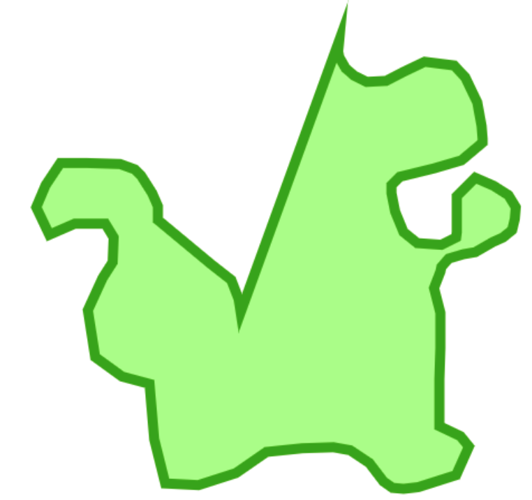
Here’s what the tessellation looks like:

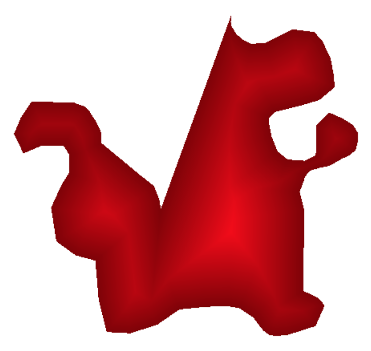
Rendering the signed distance:
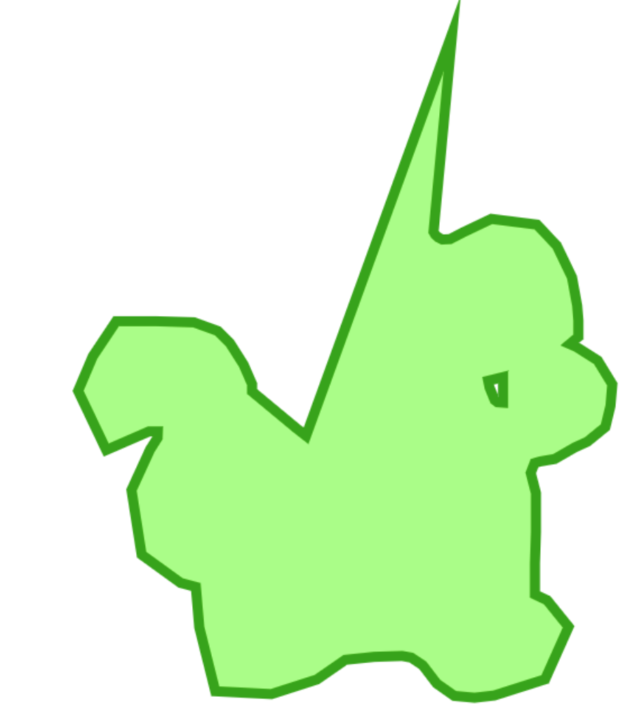
Rendering an antialiased outline and a fill in a single draw call:
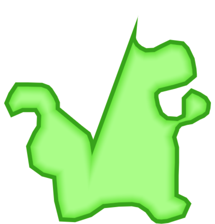
Using the same tessellation to render buffered polygons with no double drawing:
and shrunk polygons:

insets:
no examples yet for: shadows, inset patterns (for example, the water here)
Signed distance tessellation vs signed distance fields
- signed distance tessellation has a smaller memory footprint than signed distance fields because they don’t need a ton of textures
- signed distance tessellation doesn’t need texture lookups
- signed distance tessellation could avoid overdraw from shading transparent fragments
- signed distance tessellation could have better sub pixel accuracy
- signed distance tessellations could be harder to generate correctly than signed distance fields. And maybe more expensive, but maybe not.
- handling degenerate polygons could be harder with signed distance tessellations
- geometries used for signed distance fields would still need to be buffered so that outlines can be rendered. This is part of the core implementation of signed distance tessellation.
Straight skeletons
Creating this tessellation is mostly a matter of finding the straight skeleton of the geometry (thanks @anandthakker for pointing me in the right direction). This paper provides an algorithm for generating straight skeletons.
The distances produced by a straight skeleton are a bit different than a regular signed distance field. In a straight skeleton, reflex corners produce miters. In a signed distance field, reflex corners produce a round join. Miters are great, but not always the right choice.
The algorithm would need to be extended to support round and bevelled corners. Both should be doable while sticking to the core straight skeleton algorithm. For bevels, the general idea would be to add zero-length line segments in the middle of sharp corners. Circles could be faked in a similar way by adding multiple “pie slice” triangles to fake roundness. We currently use this approach for round line joins. I think true round corners might be possible but that's harder.
The algorithm also needs to be tweaked to handle:
- extending the skeleton outward from the geometry
- lines instead of polygons
- self-intersecting lines
(scattered thoughts on a signed distance tessellation with true round corners)
I realize this probably isn't very coherent: Introducing round corners adds curves to the produced skeleton. Curves are probably a lot harder and more expensive to work with. We also can't triangulate them. But the curves in the skeleton can only happen when a round corner extends and hits a straight edge. When circles extend and hit circles the boundary between them is straight. And edges extending to hit edges are straight as well. We could produce a skeleton with straight segments where each pixel within a polygon could be nearer to a round corner or an edge. We could encode both into the vertex and have the fragment shader determine which is closer at render time. This would avoid dealing with calculating the curved boundaries. I'm not sure, but I think it might be possible to extend the skeleton algorithm to handle this.
Algorithm performance
The biggest open question is whether we could generate these skeletons fast enough. I don’t know. We’d need to invest serious effort into implementing this before we could know. I’m optimistic.
The basic straight skeleton algorithm is O(nm + n log n) where n is the number of vertices and m is the number of reflex vertices. Handling convex polygons is cheap. It’s the concaveness that becomes expensive because you need to search for intersections with opposite edges.
But we have an advantage: we don’t really need a complete straight skeleton. All we need is a straight skeleton for a small area close to the edge of the geometry. We only need the skeleton for the area covered by the outline or shadow or inset. This makes finding the opposite edges much cheaper because we can use a grid index to get only the nearby edges. I think this would cut the algorithm down to something like O(n * k^2) where k is the width of the outline/inset/shadow.
The center part of the polygons not reached by the skeleton would be triangulated with earcut. This means we only need the slower skeleton tessellation for new features (outline, inset, shadow). Existing maps would not suffer a performance hit.
skeleton limited to nearest 40px:

signed distance rendering:

Vertex format
If we want to avoid shading extra transparent fragments we can use a point + extrusion approach. This might look something like:
4 bytes     x, y pos
2 bytes     extrusion x, y
1 byte      signed distance at x, y
1 byte      max extrusion length
Conclusion
Signed distance tessellations can be used to render outlines, antialiasing, insets, offset lines and shadows. The big question is whether we can calculate the tessellation fast enough. I think it might be possible.
My very messy and slow implementation used to generate the skeletons, tessellation and examples: https://github.com/mapbox/mapbox-gl-js/tree/signed-distance-tessellation
Possible next steps:
- experimentation with bevels and round joins to see if there are any pitfalls there
- start on a more optimized and careful implementation that we can benchmark
@mapbox/gl-core
 ansis
ansis
All 9 comments
Wow @ansis, thanks for the reminder of why working at Mapbox is so fun. 🙂
I'm a little confused by what's going on where the dinosaur's tail meets its butt:

Why is that crease so deep? I have a vague idea that it's tied to the various join logic choices you mentioned, but it doesn't seem to follow the "all the fragments within a single triangle are closest to the same edge" policy. Does this mean something like, with the current algorithm, to avoid creases tending towards infinitely long as the angle of a join tended towards 0, we'd have to insert the zero-length line segments you mentioned?
 ChrisLoer
on 14 Jun 2018
ChrisLoer
on 14 Jun 2018
Why is that crease so deep?
The miter at the top would grow much faster in length than the stroke on the other side. The point in the middle of the crease is the point where the miter would first touch the stroke on the other side if you made the stroke width large enough.
"all the fragments within a single triangle are closest to the same edge" was a bit of a lie. The distance that matters for straight skeletons is the distance to the infinite line, not the line segment. The distance used by traditional signed distance fields is the distance to the segment. Using the distance to the line produces miters. Using the distance to the line segment produces round joins.
Even that is only partially true. The definition of a straight skeleton is actually more complicated than "all the fragments within a polygon are closest to the same line" because there are exceptions. The actual definition is based on a shrinking process:
The straight skeleton of a polygon is defined by a continuous shrinking process in which the edges of the polygon are moved inwards parallel to themselves at a constant speed. As the edges move in this way, the vertices where pairs of edges meet also move, at speeds that depend on the angle of the vertex. If one of these moving vertices collides with a nonadjacent edge, the polygon is split in two by the collision, and the process continues in each part.

Rather than talk about the distance to the edge, it might have been more correct to say something like:
If you increased the width of a stroke of the polygon continuously, each fragment would get covered first by some edge. All fragments within a triangle would get covered first by the same edge.
Expanding edges with miters is equivalent to finding a straight skeleton. Expanding with round or bevelled joins would involve inserting additional expanding edges at reflex vertices.
ansis
on 14 Jun 2018
This is really awesome!
All we need is a straight skeleton for a small area close to the edge of the geometry. We only need the skeleton for the area covered by the outline or shadow or inset. This makes finding the opposite edges much cheaper because we can use a grid index to get only the nearby edges.
Question — how does this work w.r.t. zooming? If partial straight skeleton tesselation is expensive, it will only happen once when the data is loaded or the style is changed, but does that mean that the width of the shadow/inset/outline have to be fixed (in polygon coordinates)? How do we support smoothly changing the shadow/inset/outline size as we zoom?
It’s the concaveness that becomes expensive because you need to search for intersections with opposite edges.
The paper algorithm uses a full loop over all segments for each concave vertex to find the "opposite" one, but I'm wondering if we could improve upon that with smarter search over indexed concave vertices? I have a vague algorithm to try out in mind (on top of kdbush) that resembles what I did in concaveman (see the custom kNN metrics section near the end of my post). Having a fast full straight skeleton implementation would be very beneficial beyond GL JS use cases.
 mourner
on 15 Jun 2018
mourner
on 15 Jun 2018
BTW, just noticed that the Wikipedia article on straight skeletons describes this paper as incorrect:
Petr Felkel and Štěpán Obdržálek designed an algorithm that is said to have an efficiency of O(nr + n log r).[6][7] However, it has been reported that their algorithm is incorrect.[8][9]
I couldn't access the content of those footnotes yet, but we probably want to explore why it's considered incorrect.
mourner
on 15 Jun 2018
This paper (citation [9] from the quote above) describes the incorrectness and what looks like a pretty simple fix: http://www.cs.technion.ac.il/~barequet/theses/yakersberg-msc-thesis.pdf. I couldn't see the paper referenced by [8], as it was behind a paywall, so I don't know if that paper mentions the same flaw or a different one.
The linked paper also discusses triangulating the faces produced by the straight skeleton, but I haven't read that part to see if it would be useful to us.
 anandthakker
on 15 Jun 2018
anandthakker
on 15 Jun 2018
Question — how does this work w.r.t. zooming? If partial straight skeleton tesselation is expensive, it will only happen once when the data is loaded or the style is changed, but does that mean that the width of the shadow/inset/outline have to be fixed (in polygon coordinates)? How do we support smoothly changing the shadow/inset/outline size as we zoom?
The width of the shadow/inset/outline does not need to be fixed, but it would have a fixed maximum. We could smoothly change the shadow/inset/outline as long as it is below that maximum. Depending on how that maximum is set, it might be possible to hit it when zooming out enough. For lines and outlines if we use a point + extrusion approach we could still render wider outlines, they might just have overlap.
The paper algorithm uses a full loop over all segments for each concave vertex to find the "opposite" one, but I'm wondering if we could improve upon that with smarter search over indexed concave vertices? I have a vague algorithm to try out in mind (on top of kdbush) that resembles what I did in concaveman (see the custom kNN metrics section near the end of my post).
Yep, interesting...
ansis
on 18 Jun 2018
Also, a quick note about seams and tile edges:
For buffered rendering we would need a buffer at least as big as the maximum shadow/inset/outline distance to avoid artifacts. For bufferless rendering we'd have to reskeletonize parts of the geometry after reconstructing geometries from multiple tiles.
ansis
on 18 Jun 2018
Some small notes about calculating Straight Skeletons: At the group of Martin Held [4] quite some research has been performed recently on Straight Skeletons (and approaches to calculate it).
One approach is by means of what they call Motorcycle Graphs [1]. I remember that somewhere it was mentioned (may be a different paper) that this algorithm could be sped up by using the GPU (but that the authors not implemented this).
Another is based on Kinetic Triangulations [3], for which you first calculate a Delaunay triangulation and then determine when triangles their area becomes zero, if you let the vertices move in the direction of the bisecting lines.
See also [2] for more interesting reads on skeleton like structures.
[1] https://www.sthu.org/research/publications/files/HuHe11.pdf
[2] https://www.palfrader.org/research/
[3] https://www.palfrader.org/research/2013/Palfrader%20-%20Computing%20Straight%20Skeletons%20by%20Means%20of%20Kinetic%20Triangulations,%202013%20[Palfrader13].pdf
[4] https://www.cosy.sbg.ac.at/~held/projects/wsk/wsk.html
 bmmeijers
on 29 Oct 2018
bmmeijers
on 29 Oct 2018
@bmmeijers thanks!
ansis
on 17 Apr 2019
Related issues
 shotor
·
3Comments
shotor
·
3Comments
 PBrockmann
·
3Comments
PBrockmann
·
3Comments
 BernhardRode
·
3Comments
BernhardRode
·
3Comments
 samanpwbb
·
3Comments
samanpwbb
·
3Comments
 yoursweater
·
3Comments
yoursweater
·
3Comments
Most helpful comment
Some small notes about calculating Straight Skeletons: At the group of Martin Held [4] quite some research has been performed recently on Straight Skeletons (and approaches to calculate it).
One approach is by means of what they call Motorcycle Graphs [1]. I remember that somewhere it was mentioned (may be a different paper) that this algorithm could be sped up by using the GPU (but that the authors not implemented this).
Another is based on Kinetic Triangulations [3], for which you first calculate a Delaunay triangulation and then determine when triangles their area becomes zero, if you let the vertices move in the direction of the bisecting lines.
See also [2] for more interesting reads on skeleton like structures.
[1] https://www.sthu.org/research/publications/files/HuHe11.pdf
[2] https://www.palfrader.org/research/
[3] https://www.palfrader.org/research/2013/Palfrader%20-%20Computing%20Straight%20Skeletons%20by%20Means%20of%20Kinetic%20Triangulations,%202013%20[Palfrader13].pdf
[4] https://www.cosy.sbg.ac.at/~held/projects/wsk/wsk.html