Klipper: [FR] Input shapers support in Klipper
Input shaping is a control technique to create a commanding signal that cancels its own vibrations. It would be great to support it in Klipper.
The code for this feature is ready and demonstrates very promising results. Only some documentation rework is pending.
@KevinOConnor, per you suggestion, I'm creating a dedicated ticket to discuss the testing and integration of input shapers to Klipper instead of #2030.
 dmbutyugin
All 133 comments
Thanks! FYI, I'm fine with merging the code now and then merging the guide when it is ready. (Unlike the previous "bezier scurve with simple trapezoid generator" in #57, I don't think there is a concern of a "new user pitfall" with this support.)
-Kevin
 KevinOConnor
on 28 Jun 2020
KevinOConnor
on 28 Jun 2020
@KevinOConnor Sounds good. I've sent a pull request #3032. Please take a look and comment.
dmbutyugin
on 29 Jun 2020
I had some random thoughts on a possible test methodology. Just a very rough idea, so take "with a grain of salt".
- Print the test object (vase mode,
max_accel=7000,SET_VELOCITY_LIMIT ACCEL_TO_DECEL=99999,SET_PRESSURE_ADVANCE ADVANCE=0,TUNING_TOWER COMMAND=SET_VELOCITY_LIMIT PARAMETER=ACCEL START=1250 FACTOR=100 BAND=5). - Look for and measure ridges on print.
2a. If measure 30hz or lower (aka .030s or greater) - then failure. Only way to improve print is to use lower acceleration. Test finished. - Configure
[input shaper]withshaper_type=zv,shaper_freq_A=<measured value>. - Print test object again (same parameters as in step 1).
- Look for and measure ridges in print.
5a. If ridges no longer in print - then success. Go on to step 6.
5b. If ridges are present and have same distance as before and print looks no better - then failure. Disable input_shaper and test finished.
5c. If ridges are present and have same distance but print looks much better - then success. Go on to step 6.
5d. If ridges are present and show a different distance, then configureshaper_freq_A=<average of measured values from tests>and setshaper_typeto mzv, ei, ei2hump, ... based on some formula (TBD) that uses the range of measured ridges from tests. Repeat steps 4&5 with new settings. - If using input_shaper, then print out a "rounding of the corner test print". (I'm thinking of a simple 2mm high object with a few holes in it that can show gaps in surface filling.) Print it with both input_shaper disabled and enabled.
6a. If gaps are introduced by input_shaper and quality is too low to be acceptable - then failure. Disable input_shaper and test finished.
6b. Otherwise, success. Use input_shaper as configured. Be aware of what to look for wrt "rounding of the corner" and "ridges".
Thoughts?
-Kevin
KevinOConnor
on 30 Jun 2020
I was thinking about probably even simpler basic tuning, along the lines:
- bump max_accel and max_accel_to_decel to 7000 in printer.cfg;
- disable pressure advance;
- print the ringing model without input shaping and acceleration TUNING_TOWER, measure frequencies per axis;
- if unsuccessful (i.e. no clear period visible) - more advanced tuning is required;
- otherwise, put measured frequencies into [input_shaper] section and enable MZV shaper;
- print the ringing model again in the same manner (this time with MZV);
- if the ringing is gone - full success, otherwise measure the ringing frequencies on the newly printed test;
- if they are different - more advanced shaper is needed (maybe it can be chosen with the help of a script that plots shapers response);
- if they are the same, but ringing is still there, try to also print the ringing model again, but with EI shaper now;
- if EI shaper is better, stick with it, otherwise revert to MZV;
Now, for the selected shaper there is already an acceleration TUNING_TOWER test print. One can choose max_accel from this test such that both:
- ringing is acceptable;
- corners are not smooth yet (since PA is disabled, the corners should still show 'bumps' from insufficient PA).
Here I'm hoping that max_accel will still be higher than what is normally required to reduce ringing without input shaping (so that there is some gain). One can also make a choice between MZV and EI shapers based on the the smoothing of the corners and which max_accel they can take as a result (i.e. if one has to take too low max_accel for EI shaper due to smoothing - it might be better to use MZV and higher accelerations). Also, if the frequency is way too low (e.g. below ~20 Hz), one may also try printing ZV shaper and see if it is still acceptable vs MZV.
Now what I'm now working on in terms of documentation is the description of the more advanced tuning process, and some useful technical details about available input shapers (e.g. which range of frequencies they reduce resonances in). It should be similar to what I suggested earlier to you, Kevin - just guessing by trying several ringing frequencies with 3-hump EI shaper, and choosing the highest frequency that still shows good or acceptable results. Then one can can try 2-hump Ei shaper and even just EI shaper by adjusting the shaper frequency accordingly from 3-hump EI shaper.
dmbutyugin
on 1 Jul 2020
FYI, I'm seeing pretty bad "rounding of the corners" with 2hump_ei on my m2 printer. So, although I saw excellent suppression of ghosting on extreme accel tests, it's not a clear quality improvement for regular day-to-day prints. At some point I plan to retry the tests with just the "ei" shaper to see if I can strike a balance between "rounding" and "ghosting".
Below are some pics of a simple case lid (if curious, it's based on the stl at https://github.com/KevinOConnor/humidwifi/tree/master/case ). This is with my normal "bulk printing" speeds: max_accel=3000, max_accel_to_decel=500, print velocity=100, external perimeter velocity=50, layer height=0.28. These were all done with your latest code from #3032 .
No input-shaping (there are some blemishes, but they aren't that noticeable):

With shaper_type=2hump_ei, shaper_freq=40 (the blemishes are pretty bad):

Just for kicks, I also ran it with shaper_type=3hump_ei, shaper_freq=35 (blemishes also extend to the side wall):

I was thinking about probably even simpler basic tuning, along the lines
Sounds good to me!
Now what I'm now working on in terms of documentation is the description of the more advanced tuning process
FWIW, given the issue with "rounding", I wonder if the advanced advice might ultimately be: "deploy hardware frame stiffeners", and/or "accept that you have to print at low accel/speed".
Cheers,
-Kevin
KevinOConnor
on 1 Jul 2020
FYI, here's an overview pic of three lids mentioned previously (from left to right - no input shaping, 2hump_ei/40hz, 3hump_ei/35hz):

-Kevin
KevinOConnor
on 1 Jul 2020
@KevinOConnor That's strange. FWIW, I've been using 2hump EI shaper for some time on my printer, because of wider spectrum of resonances on a delta. I used it mostly for test prints, but did some functional prints too, and didn't notice much of that effect. But there are differences in my setup:
- 2-hump EI shaper is at 51 Hz, not 40 Hz; the difference may still be noticeable between 40 and 50 Hz.
- I'm also using S-Curve acceleration and adaptive acceleration control (so, essentially
scurve-shapingbranch); the relevant parameters are max_accel = 5000 (accel_to_decel = 2500), min_accel = 1500, ao=4, square_corner_velocity=5. - I mostly sliced models with 'lines' top and bottom infill, not zig-zag (Cura) that I frequently used in the past; not sure what you use and if it can affect anything.
A couple of recent prints with 2hump EI shaper as described above:

One mount for accelerometer for a delta smart effector (PLA). There's a bit of underextrusion and some gaps that were simply not filled by the slicer, but no described effect.

A box for Raspberry Pi (top cover, PETG). Also I believe no such defect. Both printed at 100 mm/sec infill and inner, 50 mm/sec outer perimeters.
FWIW, I've seen similar effect in the past on scurve-smoothing branch too, where infill lines fail to connect to the perimeters (usually of inner holes). Given that smoothing was very similar to ZV shaper, it is unlikely that it was related to smoothing. I suspect it was related to some processes in the hotend.
In your case, I'm not sure. But it does look like the problem exists regardless of input shaping, but it is possible that input shaping exacerbates it. Also, admittedly 35 Hz is too much of 3hump EI shaper. But 40 Hz 2hump EI should be somewhere on the boundary. But I did not personally test it at that config. I believe I did test it on ~46 Hz in the past, and I think I saw some rounding at high accelerations, but AFAIR closer to 4000-5000 mm/sec^2 (I might be mistaken).
dmbutyugin
on 2 Jul 2020
I followed this chapter https://github.com/dmbutyugin/klipper/blob/scurve-shaping/docs/S-Curve.md#best-tuning-conditions
with following settings enabled:
[printer]
kinematics = cartesian
max_velocity = 300
max_accel = 7000
max_accel_to_decel = 7000
max_z_velocity = 8
max_z_accel = 100

[input_shaper]
shaper_freq_x = 67
shaper_freq_y = 58
shaper_type_x = ei
shaper_type_y = ei
X-Axis:

Y-Axis:

(The "waviness" comes from vase mode extrusion with ASA filament, which starts warping badly after cooling on single walls)
I cannot see any ringing effect:
- Is this test meant to be run without shaping options enabled?
- Too low acceleration (my default is 3000)?
- Other user error?
Edit:
log attached
 Sineos
on 2 Jul 2020
Sineos
on 2 Jul 2020
@Sineos, the thing is, documentation for scurve-shaping branch is work-in-progress now and was not published yet really. That doc is still a copy-over from scurve-smoothing (as you probably have guessed, since it talks about [smooth_axis]), so much of its stuff is not relevant right now for input shaping part. I hope to finish the doc update this weekend.
Regardless of that, I think we have managed to establish good parameters for input shapers from your tests with accelerometer. Your latest test print confirms that (since you don't see any ringing). Which is really good and I suppose you can just use the config you've posted for [input_shaper] as is without further tuning. Just reduce max_accel to whatever you see reasonable (or keep it that way, FWIW). For max_accel you should actually look at your latest print you posted here and see if at any accel the corners of the test model become 'smooth' (normally the corners 'stand out' a bit due to pressure advance disabled, and it should actually stay that way, because input shaping is not a replacement of pressure advance). You should set max_accel in your config below that acceleration to avoid too aggressive smoothing of the prints.
dmbutyugin
on 2 Jul 2020
Well, I'm very happy with the results and the accelerometer testing was fun, too. Many thanks for digging so deep into this matter.
I really admire the knowledge gone into the whole Klipper project generally and such features specifically.
(Thou ever since I have done the measurements, the results are annoying the hell out of me. I need to get rid of them)
Sineos
on 4 Jul 2020
@KevinOConnor FWIW, I ran a simulation of 2-hump EI shaper in your configuration using graph_motion.py script (so, shaper_freq=40Hz, damping_ratio=0.1 (default), accel = 3000):

I took the true resonance frequency = 30 Hz somewhat arbitrarily, but lower frequencies result in smaller positional errors (and below ~25 Hz - higher vibrations). It seems that the positional errors in this case are up to ~0.1 mm max due to input shaping. I'm not sure if the gaps you observed are of that order, or larger - it is hard to tell from the pictures, and I'm not very familiar with the US coins.
Separately, at 50 Hz 2hump EI shaper gives positional errors of ~.075 mm using the aforementioned parameters - indeed smaller, but not that dramatically. But 3hump EI shaper at 35 Hz can have up to 0.3 mm positional error already, especially at direction change - this will be very noticeable.
@Sineos
(Thou ever since I have done the measurements, the results are annoying the hell out of me. I need to get rid of them)
Sorry, I did not understand this part. What is the problem with those results? Or are you talking about the test prints?
dmbutyugin
on 5 Jul 2020
@KevinOConnor FWIW, I've updated the tuning docs in scurve-shaping branch. For now they cover also adaptive S-Curve acceleration, but I will later make an excerpt from it that covers input_shaper specifically, and create a pull request for master Klipper branch.
dmbutyugin
on 6 Jul 2020
@dmbutyugin
I used it mostly for test prints, but did some functional prints too, and didn't notice much of that effect.
Interesting. I did make some additional prints and the results are reproducible. Interestingly though, I can still see the problem with ei at 55hz (though it's less noticeable). Disabling pressure advance helps a little, but doesn't solve it (and of course it leads to some stringing). It's possible temperature is making it worse (this was on PLA with temp=195). I'm using slic3r and I've configured it to use wider "extrusion widths" than the default, which may also be contributing to the problem. Also, I have top infill speed set to 100mm/s so maybe that's also making it worse.
I'm not very familiar with the US coins.
FYI, the two holes in the part have a 5mm diameter.
I'll try to see if I can find print settings that make the problem less noticeable.
-Kevin
KevinOConnor
on 6 Jul 2020
@dmbutyugin sorry
What I want to say: Every since I know of these resonance frequencies, I want to get rid of them. So it is entirely your fault, because you offered the possibility to measure it 😁 (thanks for it!)
Sineos
on 6 Jul 2020
@Sineos it is probably not what you'd want to hear, but you cannot :) It is pretty much that the laws of physics are against it. Any system has a finite rigidity, and a finite, non-zero moving mass. The resonance frequency is defined from the ratio of the two. Your only possibility is to increase the rigidity and decrease the mass, so that the resonance frequency increases. This has 2 main benefits: higher-frequency oscillations of the same energy have smaller amplitude (so are less visible), and at very high frequency they may too fine to be visible.
dmbutyugin
on 6 Jul 2020
@dmbutyugin when testing the shapers do you really want accel_order set to 2? Is this an attempt to keep print speed by simply shaping movements and using trapezoidal acceleration? Also, when running on a CoreXY what do we do if we turn it to 45 degrees and get different values? use the ones that are single stepper motor values (45 degrees to the axis?). It says we can run a second test, but then I don't know what to do with that test.
 slavedas
on 6 Jul 2020
slavedas
on 6 Jul 2020
@slavedas
@dmbutyugin when testing the shapers do you really want accel_order set to 2?
Yes, that's the idea.
Is this an attempt to keep print speed by simply shaping movements and using trapezoidal acceleration?
It is an attempt to minimize the influence of multiple things at once. Also, many people may find using just [input_shaper] sufficient.
Also, when running on a CoreXY what do we do if we turn it to 45 degrees and get different values? use the ones that are single stepper motor values (45 degrees to the axis?). It says we can run a second test, but then I don't know what to do with that test.
Honestly, this was (and still is) a part of experimental tuning process. We didn't see any influence so far (meaning, so far we'e only seen that X and Y axis have their resonances, and XY and YX simply have a mix of X and Y). If you decide to run this test at 45 degrees, please share the results. It may help us figure out what to do with these results. But for now you can use the results of non-rotated model measurements.
dmbutyugin
on 7 Jul 2020
@KevinOConnor, intersting.
Interestingly though, I can still see the problem with ei at 55hz (though it's less noticeable).
I do not think that positional errors with EI @ 55 Hz are noticeable. If anything, I'd think this is a good argument in favor of a theory that the true root cause of this effect is different.
I'm using slic3r and I've configured it to use wider "extrusion widths" than the default, which may also be contributing to the problem.
I'd think this may be a primary suspect (depending on how much the extrusion width is larger than the actual nozzle diameter), and the fact that PA seems to have some effect may also speak in favor of this theory. I know that many people successfully print with extrusion width > nozzle diameter. However, depending on how slicer implements attaching infill to perimeters, it may happen that the center of the toolhead doesn't really reach the perimeters when printing the infill. I.e. slicer may decide to move the toolhead only up to (nozzle_diam - infill_overlap) to the perimeter, assuming that the filament forms (half-) a circle at the end of a line, and it is sufficient that the side of that circle touches the perimeter for the infill line to stick to the perimeter. However, if the actual nozzle diameter is smaller, the filament may flow in different directions at the end of the line, and not really reach the perimeter and not stick to it. Additionally, PA may be reducing pressure at the end of a line even more, so there may be insufficient filament pushed out to reach the perimeter. Then as the toolhead moves in the opposite direction, it pulls the end of the filament line that didn't stick to the perimeter in the opposite direction, increasing the gap. This is only my theory, but I guess worth testing by setting extrusion width == nozzle diameter.
Separately, I'm not sure if the temperature can have an effect on this, but printing at higher speeds may require slightly higher temperatures than usual.
Also, I have top infill speed set to 100mm/s so maybe that's also making it worse.
I guess even if you used lower speeds for the top, it only may have masked the problem - since all internal layers would have this problem.
dmbutyugin
on 7 Jul 2020
@dmbutyugin , the manual_stepper move command is now working except when stop_on_endstop is used. When limit switch is triggered command performs as expected except subsequent commands are blocked until the expected time to finish the move has passed even the actual move stops earlier.
i.e.
MANUAL_STEPPER STEPPER=e1cam SET_POSITION=360
MANUAL_STEPPER STEPPER=e1cam MOVE=-12 SPEED=20 ACCEL=60 STOP_ON_ENDSTOP=1
Total dist is 372, expected time to finish ~20s. The system will not respond until ~20s has passed since the last command.
 ehtnevets
on 8 Jul 2020
ehtnevets
on 8 Jul 2020
@ehtnevets Just for my understanding: does this happen only on scurve-shaping branch? Or is it also happing on Klipper master branch now?
dmbutyugin
on 9 Jul 2020
Well, it happens on master branch as well. It looks like a master bug, @KevinOConnor ?
ehtnevets
on 9 Jul 2020
Hi all,
I try to tune and have some compare test print. Both using the same gcode but input_shaper. It reduces the ghost but seems lost a bit of the detail. Is it normal? Thanks!
[printer]
delta_radius = 139.8
kinematics = delta
max_velocity = 300
max_accel = 3000
max_accel_to_decel = 2000
max_z_velocity = 200
square_corner_velocity = 30
minimum_z_position = -10.0
[input_shaper]
shaper_freq_x = 30
shaper_freq_y = 30
shaper_type = ei
Left is input_shaper turn off result and right is on.

input_shaper turn off. Detail of the "String" at the tail seems more clear:

input_shaper turn on. Compare with above is a bit not clear:

The log:
klippy.log
 WindoC
on 9 Jul 2020
WindoC
on 9 Jul 2020
@WindoC
I would be curious to see the results with square_corner_velocity = 5 because to me at least 30 seems excessive.
square_corner_velocity = 30 probably great for reducing print time but not good for much else.
also why did you choose input_shaper=ei instead of mzv, my take is and @dmbutyugin please correct me if I am wrong ei has more smoothing then mzv so more chance of loosing the very fine detail.
 BlackStump
on 9 Jul 2020
BlackStump
on 9 Jul 2020
@WindoC
You could try a few things to improve, in this order:
square_corner_velocity = 30is way too high, I agree with @BlackStump. The recommendation is not to exceed the default 5 mm/sec. You should try this first (i.e. set square_corner_velocity=5), and it is likely that this will be the only thing you'd need to change. Larger values than 5 mm/sec may work, but are not guaranteed, and 30 mm/sec is really too high for quality prints.- I'm not sure if you selected
max_accel = 3000according to the recommendations, if not - please try them. I'm not sure what the outcome will be (will you get smaller or larger max_accel as a result). - If neither of the above works, you can try MZV shaper instead of EI. It is true that recommendation is to try EI shaper for delta printers, but if the resonance frequency is too low (and 30 Hz is probably at the borderline), then it may be that EI will not be the best choice. You can follow the suggested guide how to compare EI and MZV shapers.
dmbutyugin
on 9 Jul 2020
For suggestion 1. reduce the square_corner_velocity to 5. I try it and seem no different. So I perform a TUNING_TOWER test for setting SQUARE_CORNER_VELOCITY from 0 to 30. But there is no difference play with the SQUARE_CORNER_VELOCITY for the detail losing issue.


For suggestion 2, I use recommendations setting 7000 and no difference too.
For suggestion 3, Use MZV some of the detail back but the ghost increased.
I perform another TUNING_TOWER test for setting SHAPER_FREQ from 25 to 55 (type MZV). And found seem it smooth too much below frequency 40 Hz.


WindoC
on 10 Jul 2020
@WindoC
For suggestion 1. reduce the square_corner_velocity to 5. I try it and seem no different. So I perform a TUNING_TOWER test for setting SQUARE_CORNER_VELOCITY from 0 to 30.
Did you try printing a benchy with SQUARE_CORNER_VELOCITY = 5 and max_accel = 3000? And for the TUNING_TOWER test, which SQUARE_CORNER_VELOCITY did you have in printer.cfg at the time? Note that Klipper does not allow to set SQUARE_CORNER_VELOCITY from the command larger than the value in printer.cfg (so if you had SQUARE_CORNER_VELOCITY = 5 in printer.cfg, then SET_VELOCITY_LIMIT SQUARE_CORNER_VELOCITY=10 will not really do anything).
For suggestion 2, I use recommendations setting 7000 and no difference too.
Here the suggestion is not to just use 7000 max_accel. You need to set max_accel and max_accel_to_decel to 7000 _and_ run TUNING_TOWER COMMAND=SET_VELOCITY_LIMIT PARAMETER=ACCEL START=1250 FACTOR=100 BAND=5 and print the test print. Then look at the print and select the acceleration that still does not smooth the details. BTW, perhaps the current tuning test is not very good at giving that information, since it does not have small fine details.
I perform another TUNING_TOWER test for setting SHAPER_FREQ from 25 to 55 (type MZV). And found seem it smooth too much below frequency 40 Hz.
FWIW, the frequency should be set from the resonance frequency. But I think your test can be illustrative in how much MZV smooths. BTW, which acceleration did you use here? 7000? And which SQUARE_CORNER_VELOCITY?
dmbutyugin
on 10 Jul 2020
I made a model with some detail on the back which is actually hard for a slicer to reproduce.
model
picture of model before slicing

picture of model after slicing

picture of print

There is a lot of light shadowing on the print picture which looks like print ghosting but it is just light shadowing, sorry about my poor lighting and photography.
I used this command
TUNING_TOWER COMMAND=SET_VELOCITY_LIMIT PARAMETER=SQUARE_CORNER_VELOCITY START=0.5 FACTOR=0.33334 BAND=3
config details
[printer]
max_accel: 4877
square_corner_velocity: 12.0
[extruder]
pressure_advance: 0.30
[input_shaper]
shaper_freq_x: 75
shaper_freq_y: 63
shaper_type: mzv
I stand corrected at least with square_corner_velocity from 1 to 10 not affecting fine detail as I thought it would and it would seem input_shaper is not affecting fine detail either, it is producing pretty much what the slicer is slicing.
BlackStump
on 12 Jul 2020
@BlackStump I'm slightly worried that printing the text in vase mode is going to be rather difficult. I've modified a test print to have a small protrusion on each side, maybe that one will be easier to print and reason about?

I stand corrected at least with square_corner_velocity from 1 to 10 not affecting fine detail as I thought it would and it would seem input_shaper is not affecting fine detail either, it is producing pretty much what the slicer is slicing.
Perhaps. I wonder if 30 mm/sec is still too much? Also note that you have much higher frequencies - 75 and 63 Hz, at least 2x more than 30 Hz. This makes a huge difference.
@WindoC Did you manage to get anywhere with the tuning? If anything, I would suggest you try tuning from the start (or did you do that already?), especially now that the model has some small details that may help figure out the right parameters. Separately, my thinking is that if 30 Hz is true for your printer, for EI shaper you'd need to use ~5 mm/sec square_corner_velocity and decrease the acceleration to ~2000 mm/sec^2 as 3000 mm/sec^2 may be too much for that low resonance frequency.
dmbutyugin
on 12 Jul 2020
@dmbutyugin Thanks. I will try it later.
30 Hz seems is the best setting for me. I think it is a trade-off to turn on "Input shapers" for my case. Still, the enhancement is not bad.
WindoC
on 12 Jul 2020
Hi,
i've tried measuring the ringing with ADXL345 on an ender3 (direct drive with stock stepper and glass bed).
this are the result:

vib-th-x.txt

This is the actual configuration, not perfect, but better then everything i've tried until now.
`
[printer]
kinematics: cartesian
max_velocity: 300
max_accel: 3000
max_accel_to_decel: 10000
max_z_velocity: 10
max_z_accel: 100
square_corner_velocity: 5
[input_shaper]
shaper_freq_x: 46
shaper_freq_y: 42.5
damping_ratio_x: 0.05
damping_ratio_y: 0.05
shaper_type: ei
[scurve]
acceleration_order: 4
min_accel: 800
`
X master

X EI

X EI s-curve

Y master

Y EI s-curve

Do you think i'm doing it right?
If you need some particular test, feel free to ask.
For the Y axis it stop every time at 82hz with the following error:
Traceback (most recent call last):
File "/home/pi/klipper/klippy/klippy.py", line 185, in run
   self.reactor.run()
File "/home/pi/klipper/klippy/reactor.py", line 251, in run
   g_next.switch()
File "/home/pi/klipper/klippy/reactor.py", line 278, in _dispatch_loop
   timeout = self._check_timers(eventtime)
File "/home/pi/klipper/klippy/reactor.py", line 136, in _check_timers
   t.waketime = waketime = t.callback(eventtime)
File "/home/pi/klipper/klippy/extras/resonance_tester.py", line 132, in test_single_freq
   probe_time, meas_time, meas_offset, raw_output)
File "/home/pi/klipper/klippy/extras/resonance_tester.py", line 285, in _run_test
   meas_time, meas_offset)
File "/home/pi/klipper/klippy/extras/resonance_tester.py", line 371, in _calc_vibrations
   self._integrate(raw_values, i, j),
File "/home/pi/klipper/klippy/extras/resonance_tester.py", line 384, in _integrate
   avg_ax = integrate(raw_values.ax)
File "/home/pi/klipper/klippy/extras/resonance_tester.py", line 383, in integrate
return res / T
ZeroDivisionError: float division by zero
klippy.log
the command was:
TEST_VIBRATIONS X=117 Y=132 Z=20 AXIS=Y FREQ_START=10 FREQ_END=120 FREQ_STEP=0.5 OUTPUT=/tmp/vib-th-y.csv
with max_accel and max_accel_to_decel set to 10000.
 alocin73
on 12 Jul 2020
alocin73
on 12 Jul 2020
@WindoC
30 Hz seems is the best setting for me. I think it is a trade-off to turn on "Input shapers" for my case. Still, the enhancement is not bad.
Yes, 30 Hz is determined from the properties of the printer, so it should be set as it is, there is not much you can change here. You can still see if some other closer value works better with MZV, or use EI with 30 Hz. But, by adjusting other parameters (square_corner_velocity, max_accel) you can hopefully get less smoothing.
Edit: I would also invest into making the printer more rigid, so that the resonance frequency increases. For delta printers, there is this nice mod. I have installed it on my printer, and I can highly recommend it: it makes the frame very stiff, and reduces its wobbling quite a bit.
dmbutyugin
on 12 Jul 2020
@alocin73 Thanks for sharing your experience!
A bit of feedback:
- I would not change damping_ratio to 0.05, I'd leave it at default (which is 0.1). Or was there a reason for you to change it?
- You could probably slightly adjust the settings to
shaper_freq_y = 40andshaper_freq_x = 50- it may better cover different resonances that you have measured with the accelerometer.
For the Y axis it stop every time at 82hz with the following error:
I'll need to check, but it is probably that the vibrations get too small for the code to successfully find the start of the move. In general, the amplitude of vibrations is relatively small in your measurements, I don't know exactly why is that.
dmbutyugin
on 12 Jul 2020
@alocin73 Thanks for sharing your experience!
A bit of feedback:
- I would not change damping_ratio to 0.05, I'd leave it at default (which is 0.1). Or was there a reason for you to change it?

Looking at this graf, the intent was to smooth less the lowest resonance to avoid to mutch smoothing of the corner.
Surely i dont understand how it work :)
Just to know, when is advisable to change the damping ratio?
- You could probably slightly adjust the settings to
shaper_freq_y = 40andshaper_freq_x = 50- it may better cover different resonances that you have measured with the accelerometer.
I've chosen the ones in the middle of the resonances for the X and Y axis.
Must the values be chosen taking into account the resonance on all axes?
For the Y axis it stop every time at 82hz with the following error:
I'll need to check, but it is probably that the vibrations get too small for the code to successfully find the start of the move. In general, the amplitude of vibrations is relatively small in your measurements, I don't know exactly why is that.
It can be the stiffener on the frame?
Or the soft gum under the printer?

P.S. I'm trying to write correctly in English, sorry for mistakes
alocin73
on 12 Jul 2020
@dmbutyugin
I'm slightly worried that printing the text in vase mode is going to be rather difficult. I've modified a test print to have a small protrusion on each side, maybe that one will be easier to print and reason about?
MY goal was always to make a model that is fast to print and to use as little as possible material but be difficult enough to print to show any problems that may or may not be there. S3D will slice the model in vase mode, ideamaker also had no problems reproducing to text tho I did not check if it was in vase mode. Of course layer height/width play a part in fine detail reproduction.
Perhaps. I wonder if 30 mm/sec is still too much? Also note that you have much higher frequencies - 75 and 63 Hz, at least 2x more than 30 Hz. This makes a huge difference.
I agree 30 is too high, 5 is default and should be the parameter to use for issues and testing. Yes too many variables with all the different printers out in the wild and the ever increasing variation in build qualities.
BlackStump
on 13 Jul 2020
Do you think their is any benefit to increasing sqv past say 10 or even 5 or really won't see time decrease. Also if mzv works great is it worth trying zv for less shaping if i barely saw ringing all the way to 7000 at 200mms and at 120mms had to really angle light to see one or two rings . at 5000 accel no ringing at 200mms. so i would say mzv is amazing btw i am at 50hz both axis on a corexy and i was running 4000 accel before with results that were identical to my 7000 accel settings now maybe a little worse actually. I was running 10 sqv tho and now am running 5 as per your rec
 robthide37
on 13 Jul 2020
robthide37
on 13 Jul 2020
Also i do believe that lack of positional error is making previous "workarounds" now ineffective. Like kevin had said i am using a .6 width with .4 nozzle and now i notice perimeters not reaching as well as they were but they were set to default superslicer overlap aka 15 percent and they should technically be 0 to just touch and rob around 30 to have no gaps . I actually have to think about this one now cause i am really not sure which way should go in a perfect zero backlash and zero filament spring theoretical application.
robthide37
on 13 Jul 2020
- I would not change damping_ratio to 0.05, I'd leave it at default (which is 0.1). Or was there a reason for you to change it?
Looking at this graf, the intent was to smooth less the lowest resonance to avoid to mutch smoothing of the corner.
Surely i dont understand how it work :)
Hmm, I fail to understand how this chart relates to your point regarding damping ratio. So maybe it is that. Basically, the top chart shows how much of vibrations is left at the given frequencies and several possible damping ratios of the printer (0.05, 0.1, 0.2) when the shaper is configured for 42.5 Hz and damping_ratio = 0.1. So, the lower the better, and different lines correspond to different damping ratios _of the printer_. Normally, you don't know which line corresponds to _your printer_ (because you don't really know the true damping ratio), but this chart demonstrates that the reduction of ringing is good for many possible damping ratios (0.05 is quite low and means not much of vibrations dissipation, and 0.2 is relatively high and vibrations quickly stop in this case) - that's why I think that 0.1 (the value for the _input shaper_) is a good default value.
Just to know, when is advisable to change the damping ratio?
Well, pretty much, never :) Unless you can confirm the actual value with some elaborate measurements.
- You could probably slightly adjust the settings to
shaper_freq_y = 40andshaper_freq_x = 50- it may better cover different resonances that you have measured with the accelerometer.I've chosen the ones in the middle of the resonances for the X and Y axis.
Must the values be chosen taking into account the resonance on all axes?
I would think it is better that way. Because it looks like certain frequencies excite vibrations of _other axes_ (e.g. vibrations of X axis at 60-61 Hz seem to excite vibrations in Y direction). But these are still vibrations, so I would think it makes sense to cancel those too. So I would suggest you to try that configuration (50/40 Hz for X/Y) and see if that improves, or even not makes things worse visibly, I would keep that configuration.
Separately, for Y axis vibrations, did you move the sensor to the bed?
I'll need to check, but it is probably that the vibrations get too small for the code to successfully find the start of the move. In general, the amplitude of vibrations is relatively small in your measurements, I don't know exactly why is that.
It can be the stiffener on the frame?
Or the soft gum under the printer?
I am not sure. It might also be the case that the frame of your printer has some very low-frequency resonances (the response chart grows towards 10 Hz), but you have some frame stiffeners, so it probably wouldn't be the case for at least X axis. You can check the belt tension however and if you have a play in any of the moving parts.
dmbutyugin
on 13 Jul 2020
@BlackStump
MY goal was always to make a model that is fast to print and to use as little as possible material but be difficult enough to print to show any problems that may or may not be there. S3D will slice the model in vase mode, ideamaker also had no problems reproducing to text tho I did not check if it was in vase mode.
Sure, any feedback and suggestions are welcome. I welcome the feedback as to which approach better demonstrates the defects of smoothing, and I am fine either way.
dmbutyugin
on 13 Jul 2020
@robthide37
Do you think their is any benefit to increasing sqv past say 10 or even 5 or really won't see time decrease.
The feedback from Kevin previously was that there isn't much point of increasing sqv past 5 mm/sec, as you get diminishing returns in print times. I'd say there's definitely no reason to go past 10 mm/sec (and better leave at 5 mm/sec, or at least confirm with some testing that 10 mm/sec does not make things worse).
Separately, I remember using higher sqv to reduce the effects of pressure advance - basically, since the toolhead would traverse the angles at higher velocity, it would have to retract less, which could make a difference on long bowden setups. But since the changes in PA algorithm last year, I'd say it is no longer worth it, as now you can get similar effect by bumping acceleration instead.
Also if mzv works great is it worth trying zv for less shaping if i barely saw ringing all the way to 7000 at 200mms and at 120mms had to really angle light to see one or two rings
Well, if it is all good, and you don't see any smoothing issues, then I'd say no need. Also, 50 Hz frequency should be well within a reasonable zone for MZV shaper.
Also i do believe that lack of positional error is making previous "workarounds" now ineffective. Like kevin had said i am using a .6 width with .4 nozzle and now i notice perimeters not reaching as well as they were but they were set to default superslicer overlap aka 15 percent and they should technically be 0 to just touch and rob around 30 to have no gaps .
I'm not sure, which 'previous "workarounds"' are you talking about? What have you been using before? Separately, I wounder if you would get those gaps at 7000 accel without input_shaper too? At any rate, it would be great to test less aggressive overextrusion mode, like 0.5 or better 0.45 line with 0.4 nozzle and see if the problem disappears?
dmbutyugin
on 13 Jul 2020
I mean 3d printing before klipper and even more so your fork has been a
series of estimations and compromises and then we would mitigate these
problems with pseudo solutions. Like combing,coasting and archaic jerk. And
I am wondering if line width being larger and overlap "besides when for
backlash" have been a case of this. Basically I almost feel like everything
I thought i knew should go out the window and I should start from scratch
as far as tuning my printer.Basically I really am nowhere near as advanced
as most of you but i feel a combo of pressure advance and the tool path
following more accurate path would make infill not squish into the
perimeter as much .
On Mon, Jul 13, 2020, 3:07 PM Dmitry Butyugin notifications@github.com
wrote:
@robthide37 https://github.com/robthide37
Do you think their is any benefit to increasing sqv past say 10 or even 5
or really won't see time decrease.The feedback from Kevin previously was that there isn't much point of
increasing sqv past 5 mm/sec, as you get diminishing returns in print
times. I'd say there's definitely no reason to go past 10 mm/sec (and
better leave at 5 mm/sec, or at least confirm with some testing that 10
mm/sec does not make things worse).Separately, I remember using higher sqv to reduce the effects of pressure
advance - basically, since the toolhead would traverse the angles at higher
velocity, it would have to retract less, which could make a difference on
long bowden setups. But since the changes in PA algorithm last year, I'd
say it is no longer worth it, as now you can get similar effect by bumping
acceleration instead.Also if mzv works great is it worth trying zv for less shaping if i barely
saw ringing all the way to 7000 at 200mms and at 120mms had to really angle
light to see one or two ringsWell, if it is all good, and you don't see any smoothing issues, then I'd
say no need. Also, 50 Hz frequency should be well within a reasonable zone
for MZV shaper.Also i do believe that lack of positional error is making previous
"workarounds" now ineffective. Like kevin had said i am using a .6 width
with .4 nozzle and now i notice perimeters not reaching as well as they
were but they were set to default superslicer overlap aka 15 percent and
they should technically be 0 to just touch and rob around 30 to have no
gaps .I'm not sure, which 'previous "workarounds"' are you talking about? What
have you been using before? Separately, I wounder if you would get those
gaps at 7000 accel without input_shaper too? At any rate, it would be great
to test less aggressive overextrusion mode, like 0.5 or better 0.45 line
with 0.4 nozzle and see if the problem disappears?—
You are receiving this because you were mentioned.
Reply to this email directly, view it on GitHub
https://github.com/KevinOConnor/klipper/issues/3025#issuecomment-657738149,
or unsubscribe
https://github.com/notifications/unsubscribe-auth/APNYI6AVHEJIL2I65YYRT6TR3NLQBANCNFSM4OKGVTIA
.
robthide37
on 13 Jul 2020
@robthide37,
the tool path following more accurate path would make infill not squish into the perimeter as much .
That is a good point. @KevinOConnor I'd think this could be another point: when the toolhead decelerates, it typically 'overshoots' its commanded position, and goes further than it is supposed to. In this case, when printing the infill, the infill could stick better to the perimeters. Now that we are 'fixing' the toolhead path with the input shaper, even without too much of smoothing, the toolhead may not overshoot its target position and this could make infill adhesion to the perimeters worse. If that's what really is happening here, then improving the toolhead cornering could reduce the print quality ironically (saying it differently, poor cornering could improve the print quality counter-intuitively). Then, we would need to tune infill overlap differently.
dmbutyugin
on 13 Jul 2020
Hmm, I fail to understand how this chart relates to your point regarding damping ratio.>
No, it's my fault, i pretend to understand too much some time(often...), thanks for the explanation.
Well, pretty much, never :) Unless you can confirm the actual value with some elaborate measurements.>
OK
Separately, for Y axis vibrations, did you move the sensor to the bed?
No, the sensor was on the tool head.
I am not sure. It might also be the case that the frame of your printer has some very low-frequency resonances (the response chart grows towards 10 Hz), but you have some frame stiffeners, so it probably wouldn't be the case for at least X axis. You can check the belt tension however and if you have a play in any of the moving parts.
I checked, and the belt were too loose.
I also moved the sensor from the bl-touch bracket to the heatblock.
I measured again, this time on the tool-head and on the bed:

vib_th_X.txt

vib_th_Y.txt

vib_BED_X.txt

vib_BED_Y.txt
I'll try some new print with the settings you suggest and the default damping ratio this time.
Thanks again.
alocin73
on 14 Jul 2020
@dmbutyugin
Thanks I am with you in regards to using what ever model that works to show the defect, I printed your model with the updated notches but I can not reproduce any fine detail problems on either model so we need someone that does have a issue to report back if the new notches do there job. In summary I can not fault the input_shaper.
BlackStump
on 14 Jul 2020
@dmbutyugin , FWIW, the reason I use a larger than default extrusion width is because of https://github.com/slic3r/Slic3r/issues/3449 . That is, the default slic3r extrusion width settings actually cause the extruded tracks to overlap. So, I increased the extrusion widths so that the tracks would actually match the nozzle width..
As far as I know, all the recent slic3r derivatives (eg, prusa slicer) have this same bizarre behaviour.
To your point, though, since setting slic3r's extrusion widths are so complicated, it's unclear to me how slic3r implements its "infill/perimeters overlap" setting.. I've been meaning to investigate, but haven't had a chance yet.
-Kevin
KevinOConnor
on 14 Jul 2020
i went with .6 cause this https://dyzedesign.com/2018/07/3d-print-speed-calculation-find-optimal-speed/
it says speed but i suggest a quick read as it is about line width
robthide37
on 14 Jul 2020
Also their is not much clear info on max accel to decel the test says to set it to 7000 as well but then to delete when done which would put it to half of the accel. Should we be setting it to equal the max accel we find or is it just to make sure the test isn't limited but in real world printing we don't want it to equal the accel
robthide37
on 14 Jul 2020
https://s.amsu.ng/ZYZGta8m0emN 353mms @7000 ringing test
Also I managed 353 mms with 7000 accel and no ringing this input shaping is amazing
robthide37
on 14 Jul 2020
@dmbutyugin , FWIW, the reason I use a larger than default extrusion width is because of slic3r/Slic3r#3449 . That is, the default slic3r extrusion width settings actually cause the extruded tracks to overlap. So, I increased the extrusion widths so that the tracks would actually match the nozzle width..
As far as I know, all the recent slic3r derivatives (eg, prusa slicer) have this same bizarre behaviour.
To your point, though, since setting slic3r's extrusion widths are so complicated, it's unclear to me how slic3r implements its "infill/perimeters overlap" setting.. I've been meaning to investigate, but haven't had a chance yet.
-Kevin
I'm glad you have your eyes on this bizarre behaviour, too. I haven't been using slic3r since I abandoned it in 2014, but it amazes me that this "feature" is still present. All it does is add noise to the GCode.
There is really two related components to this odd behaviour:
- Underextruding paths because of the "rectangular-path-paradox" i.e., our ideal paths are rectangular prisms, but physics gives us rounded sides.
- Overlapping these paths in an attempt to fill the void left by rounded sides.
The slic3r manual is nice enough to document it for us, at least:
In this documentation they describe how (and why) they underextrude paths. They also talk about how and why they overlap paths. The external perimeter remains positioned correctly, while all paths that contact it are overlapped slightly, with this formula:
spacing = extrusion_width - layer_height * (1 - PI/4)
Which, if we do the calculations, is almost always a value that is less than a full X/Y step. Essentially, purposely adding noise into the GCode that can't reliably be executed (the motor may, or may not achieve this position. It depends on a lot of things, really).
I don't know why I'm explaining all this to you, you are probably way too aware of this.
I'm not a software development expert, or a coding genius, or anything, but I've been trying to understand this problem better and I have been directed to the place in the Slic3r (fork) source code which they are implemented:
perimetergenerator.cpp(in the beginning) for the use of it.flow.cppfor the multiplication.
The PrusaSlicer fork SuperSlicer has added a feature (link to commit) that can disable this (overlapping, not underextrusion) functionality, but it's a bit convoluted for my tastes. I would much prefer that the feature is just completely removed. I think many people would immediately see print quality improvement if both the overextrusion and overlapping of paths was removed from all Slic3r variants. (which is a moot point to discuss here, on the Klipper issue tracker... but I like hearing the sound of my own keystrokes I guess)
 n8bot
on 14 Jul 2020
n8bot
on 14 Jul 2020
@robthide37
Also their is not much clear info on max accel to decel the test says to set it to 7000 as well but then to delete when done which would put it to half of the accel.
No, actually this is not how it works. max_accel_to_decel is only used to calculate the maximum velocity for the move, but Klipper uses the full acceleration for the move anyways (link). So there is no need to worry about that.
dmbutyugin
on 14 Jul 2020
@KevinOConnor
As far as I know, all the recent slic3r derivatives (eg, prusa slicer) have this same bizarre behaviour.
To your point, though, since setting slic3r's extrusion widths are so complicated, it's unclear to me how slic3r implements its "infill/perimeters overlap" setting.. I've been meaning to investigate, but haven't had a chance yet.
I see. Yes, I must admit I do not know in much details how slicers deal with cornering and overlap. Moreover, I have been using Cura for the last few years, so I have not much of experience with Slic3r. Though I am not sure if there is similarly strange behavior in Cura.
My current thinking for the results that you have observed is as follows:
- Without input shaper, the toolhead overshoot the commanded position around the ends of infill (the error can be up to ~0.2 mm with 25 Hz resonance), so this helps with infill adhesion to the perimeters.
- With 2hump_ei at 40 Hz, the error is largely corrected (the positional error can be ~0.1 mm in the opposite direction, so the total difference is up to 0.3 mm vs no input shaper). This can lead to poorer adhesion of the infill, blesmishes increase.
- 3hump_ei shaper at 35 Hz smooths too much and can give positional error at the corner of up to ~0.3 mm (+0.2 mm positional error vs 2hump_ei at 40 Hz); position is about 0.5 mm different than with no input shaping - and blemishes become very visible all across the printed part.
Some illustrative simulation (3000 mm/sec^2 accel, 2hump_ei 40 Hz on the left, 3hump_ei 35 Hz on the right), the interesting point is at around 0.25 sec:
| |
| |
|
|:--:|:--:|
Still, it would seem that there are some issues with infill and perimeter overlap, and some weirdness in how the extrusion width is handled in Slic3r (and I have no idea how this affect the filament flow through the nozzle). It would probably make sense to compare with some other slicer, e.g. Cura - even another slicer has some hiccups as well, it very well may handle this case differently. And it would be great if we could find some workaround or recommendation what to do in this case so that we could put it in the docs. Fortunately or unfortunately, it would seem that ~50 Hz of my printer is rather high and not so much prone to positional errors of both direction, so even if I tried Slic3r, I don't it would change anything on my printer.
dmbutyugin
on 14 Jul 2020
@dmbutyugin @KevinOConnor
If I was to walk away from S3D my first choice to try would be Ideamaker I have used it a few times now and for a out of the box free slicer is works pretty well.
But all slicers seem to have there quirks, kisslicer as a slicer works pretty well but the frontend is what puts me off every time.
craftware I have looked at multiple times look at the settings think to myself I should give it whirl but never do, maybe it is ok but I have not used.
icesl maybe has a lot of potential but needs programming skills to setup and get the best out of from what I can see, be nice if someone has gone and setup a klipper friendly config for icesl.
Hard to find a slicer that ticks every box and does not have it own issues.
BlackStump
on 15 Jul 2020
[...]
[icesl](https://icesl.loria.fr/download/) maybe has a lot of potential but needs programming skills to setup and get the best out of from what I can see, be nice if someone has gone and setup a klipper friendly config for icesl.
Hard to find a slicer that ticks every box and does not have it own issues.
I'm having the same slicer pains. I can not find one that works perfectly for me. That said, I'm kind of an IceSL fanboy. IceSL is the closest thing I've found to the perfect slicer, even though it's still quite a bit off from being 100% utter perfection.
What I like about IceSL is the configurable accuracy of the X/Y/Z toolpaths, and the impeccable consistency/accuracy of the extrusion amount values.
I'm still just a "Klipper observer," I have not had an opportunity to try it out yet, but I would be happy to help make a Klipper IceSL profile. I recently completed making a RepRapFirmware-specific profile template for IceSL, which could likely easily be re-purposed to work for Klipper. The profile I created can be seen here.
What are the differences in operation between RRF and Klipper? That would be the only question to answer, as well as other must-have features, and I could go ahead and make some changes to the profile to suit Klipper users.
n8bot
on 15 Jul 2020
@n8bot I would say RepRapFirmware is Gcode everywhere firmware, klipper is not. klipper Gcode
I did make a off the cuff remark about icesl because I have not actually used apart from a basic test print so I really do not have the experience to say what would be needed.
I am looking at your RRF profile and it looks very impressive.
BlackStump
on 15 Jul 2020
Thank you. I'm not sure if it's really that impressive, per se. What is impressive is the flexibility provided by IceSL to tailor the output as needed. It does not need to strictly be G-code. In theory, one could build a Lua script to pre-process a ton of the movement, as klipper does, and output a file of completely new format to send to the printer.
I digress, this might not be the most appropriate place to continue this discussion. If you go here you can create an issue in my IceSL profile repo, and we can sort out what needs to be done. I took a quick look, and I know that the temperature control Gcode will need to be changed from G10 based-commands to the traditional M104/M109 commands. This should be easy.
Please feel free to create an issue on my repo and we can go from there. (Make sure you create the issue in my forked repo -- I'm not affiliated with IceSL in any way! They'd be confused about your issue if it was on their main repo.)
n8bot
on 15 Jul 2020
@Fenixin, in the other thread you mentioned that you have ~33 Hz resonance frequency, and you did try EI shaper. Did you happen to observe an effect like described in this comment - the gaps between the infill and perimeters? If no, which slicer do you use and which line width vs the nozzle diameter?
@vadsh In the same thread about S-Curve acceleration you said that you have resonances on Y axis at 25 Hz due to large moving bed. Did you try to switch to scurve-shaping branch since then, or simply to the Klipper mainline, now that input_shaper is integrated? If yes, I have the same question: did you observe the effect of gaps between infill and perimeter lines with just [input_shaper] enabled?
dmbutyugin
on 16 Jul 2020
@Fenixin, in the other thread you mentioned that you have ~33 Hz resonance frequency, and you did try EI shaper. Did you happen to observe an effect like described in this comment - the gaps between the infill and perimeters? If no, which slicer do you use and which line width vs the nozzle diameter?
I haven't printed that much recently. I will give it a look in the next prints. Right now I use PrusaSlicer. I'll report back when I have some results.
 Fenixin
on 16 Jul 2020
Fenixin
on 16 Jul 2020
i am going to ask supermerril to take a look at this since he added the perimeter overlap control he should have no prob adding the extrusion modifier control
robthide37
on 17 Jul 2020
Some insight, to clarify things.
The PrusaSlicer fork SuperSlicer has added a feature (link to commit) that can disable this (overlapping, not underextrusion) functionality, but it's a bit convoluted for my tastes. I would much prefer that the feature is just completely removed. I think many people would immediately see print quality improvement if both the overextrusion and overlapping of paths was removed from all Slic3r variants. (which is a moot point to discuss here, on the Klipper issue tracker... but I like hearing the sound of my own keystrokes I guess)
there is no underextrusion/overextrusion. By default (100% ovelap), it will extrude exactly the volume of plastic to fill the given volume. If you set a "spacing" instead of a "width", it's exactly what you want.
If you use a "square" function, you will have problem even more with dimensional accuracy.
Which, if we do the calculations, is almost always a value that is less than a full X/Y step.
I don't see the point. The line position depends also on the model. If you grow your model by 1,1245% for whatever reason and this does not align your 'full step' again, you can't blame the slicer anymore. A gcode path will almost never be at full step, or you're being lucky & printing a very simple piece.
I can add a "xy min step" feature to discretize the gcode output, so you'll have a blocky print.
 supermerill
on 17 Jul 2020
supermerill
on 17 Jul 2020
there is no underextrusion/overextrusion.
When I said underextrusion, I was only referring to the concept of lowering the extrusion amount to accommodate the rounded-edge cross section of extrudate. This concept of underextruding the paths seems silly to me. It only seems "helpful" on prints with relatively low resolution: thick layers, with wide traces. A user could merely lower their extrusion factor manually to achieve the same effect. On prints with small layer heights and thin extrusion widths, the difference in "width" caused by this flow math is ridiculously small. There is much more error in other parts of the system than the "error" that is trying to be corrected by these calculations.
As for the path overlap -- I guess it makes sense in the context of artificially lowering extrusion amount. But why play these silly games? I do not think they add up to a better experience. They certainly don't add up to more accurate or better-looking prints.
You say that the line position depends also on the model -- it should depend ONLY on the model. The software can't reliably adjust the location of every (internal) line and ensure they line up the way they should have before making the adjustments, especially when that adjustment purposely overlaps extrusion. It will introduce additional errors and noise.
It seems a bit like the ArcCompensation that was tried and removed from slic3r, which altered the centerline of corners to attempt to correct where the plastic ends up. I don't think trying to have the slicer to automatically adjust these things is the best approach on anything but the simplest models. The best approach (IMO) is to just follow the model 100%. This is what nearly every other slicer does.
Think about a gently sloped surface with a large radius -- how is adding this random noise to every layer supposed to help? I've seen what it does compared to slicers that don't perform these antics -- it performs worse. Randomly misaligned/oddly extruded layers.
Now, are the problems in the print tests I've done cuased directly because of the underextrusion and overlap? Maybe not. But that's where I'm placing my wager. It could also be caused by the fact that the extrusion values output by the Slic3r variants fluctuate 5 times more than the slicer (IceSL) that provides the cleaner print.
I don't think anybody is asking for discretized steps. I'm certainly not. I'm just suggesting it might be useful to remove all of these weird approximations that actually, IMO, show detrimental effects, and no benefit.
If you grow your model by 1,1245% for whatever reason and this does not align your 'full step' again, you can't blame the slicer anymore.
Ok, sure. But let the errors lay where they lay. Trying to adjust errors by adding more errors seems silly to me.
We've built physical systems with physical resolution. Let's let that physical resolution dictate error, and not introduce noise to the equation. Just my opinion. [Edit: This statement is quite ironic, in retrospect, being in the "input shaper" issue thread. Buuuut I consider the firmware part of that physical system. Once we hand off control to firmware, I don't mind a little bit of the 'ol messin' about with numbers. I'm sorry if I seem opinionated or rude, I just speak frankly and my tone is often not well-chosen.]
n8bot
on 17 Jul 2020
The front and the back right both were better the back riight .15 test was perfect. I believe with the concentric and perimiter moving it actualy makes a slight oval on the back left one .I think thats why it happened. My next set i am turning off overlapping perimeters "the thinperimeter checkbox one that allows 2 perimeters converging to still print" so it uses gap fill instead and also setting both perimeter overlap to 0. I understand that it does move outside perimeter as the first setting out of the two integer value ones says the outer perimter will contribute to overlap. I would understand with that it would move the perimeter in slightly and then over extrude slightly to make up for this. I also was confused about setting line spacing manually ,is that an option currently as it seemed that supermerril was saying that would work .
overlaptesttolerance_gage.3mf.txt
robthide37
on 17 Jul 2020
i realized that the outer never moves it just allows you to set the distance between multiple inner ones an then you can also just have the inner shell not overlap the last one. See and my wife says i accomplish nothing when i stay home from work.
robthide37
on 17 Jul 2020
A user could merely lower their extrusion factor manually to achieve the same effect
that would create underextrusion, it's not the same.
On prints with small layer heights and thin extrusion widths, the difference in "width" caused by this flow math is ridiculously small.
it's on small layer heights and BIG extrusion widths that the effect is small.
You say that the line position depends also on the model -- it should depend ONLY on the model.
So the extrusion width shouldn't exist? it's nonsense.
Think about a gently sloped surface with a large radius -- how is adding this random noise to every layer supposed to help? I've seen what it does compared to slicers that don't perform these antics -- it performs worse. Randomly misaligned/oddly extruded layers.
? what 'noise' , 'antics' you speak about ?
And if a slicer is adding "Random" thing, something has gone very wrong imo. There is no random in slic3r (&derivatives).
It could also be caused by the fact that the extrusion values output by the Slic3r variants fluctuate 5 times more than the slicer (IceSL) that provides the cleaner print
depends on your settings. Also what do you mean by 'extrusion values' ? mm3/sec ?
Trying to adjust errors by adding more errors seems silly to me.
?? unless you have an angstrom nozzle diameter, you can't follow the exact shape of the object and you need to follow it from a distance. How that can be told as an 'error' ?
some lecture:
Part strength evolution with bonding between filaments in fused deposition modelling
Characterization and Optimization of
Mechanical Properties of ABS Parts Manufactured by
the Fused Deposition Modelling Process
The effects of voids on structural properties of fused
deposition modelled parts: a probabilistic approach
supermerill
on 17 Jul 2020
Doesn't the granular control of the extrusion width kinda fix alot of these problems?
robthide37
on 18 Jul 2020
@supermerill I think you're not understanding exactly what I mean when I describe the behaviour I'd prefer.
I do not want the extrusion width to be an infinitesimal. I want the extrusion width to be exactly like the user specifies, or the algorithm auto-calculates, _without any of the flow compensation that is meant to correct for the extrudate becoming oval, instead of a rectangular prism._
Alongside that, I would want the overlapping of paths that is done to compensate for the reduced flow from above to be also removed.
E.G., if we have an extrusion width of 0.4, I want that calculated extrusion value to be exactly correct for a rectangular prism of 0.4 mm wide, and layer thickness height, and x length. I want the inner perimeters to be spaced exactly the extrusion width apart, i.e., 0.4 mm -- not 0.357 or something.
That is all I'm talking about.
Edit: Oh, right, as for the "fluctuation" comment I made about E value. I just mean the consistency. There are (very small) errors somewhere in the calculation that cause the min and max extrusion rate to fluctuate ~5 times more than the values output by IceSL. See the following images:


n8bot
on 18 Jul 2020
question so when we turn the overlap to 0 percent it is still doing the flow math as if was spaced tighter ? Their is no chance it will then calculate off of the base number since its not being altered anymore . Or would it actually add more flow to try and compensate for the larger spacing ? I know i prob am not wording this best but i am not nearly as educated on the matter . in fact if i am not adding anything of value ill shut up and sit back at this point .
robthide37
on 18 Jul 2020
question so when we turn the overlap to 0 percent it is still doing the flow math as if was spaced tighter ? Their is no chance it will then calculate off of the base number since its not being altered anymore . Or would it actually add more flow to try and compensate for the larger spacing ? I know i prob am not wording this best but i am not nearly as educated on the matter . in fact if i am not adding anything of value ill shut up and sit back at this point .
I do not think the flow math automatically changes based on removing the perimeters overlap. I'm no C/C++ expert, though, so I could be wrong.
n8bot
on 18 Jul 2020
im trying this to see
tolerance_gage.3mf.txt
robthide37
on 18 Jul 2020
I confirmed yesterday that when the perimeter overlap External and Inner are both at 0%, the extrusion is still adjusted lower to "compensate for the rounded extrudate." Which, to some people, is undesirable behaviour.
I'm going to try removing the adjusted extrusion myself and see if I don't mess too much up. It should be as simple as removing all the different times it is calculated for various instances. I do not understand why it's calculated in so many places (at least three six that I know of). Wish me luck.
n8bot
on 19 Jul 2020
[...]
And if a slicer is adding "Random" thing, something has gone very wrong imo. There is no random in slic3r (&derivatives).
[...]
I was digging around in PS source, and couldn't help but notice something...
        size_t num_samples = size_t(ceil(areas.back() * samples_per_mm2));
        std::uniform_real_distribution<> random_triangle(0., double(areas.back()));
        std::uniform_real_distribution<> random_float(0., 1.);
I'm just teasing.
n8bot
on 19 Jul 2020
I confirmed yesterday that when the perimeter overlap External and Inner are both at 0%, the extrusion is still adjusted lower to "compensate for the rounded extrudate." Which, to some people, is undesirable behaviour.
I'm going to try removing the adjusted extrusion myself and see if I don't mess too much up. It should be as simple as removing all the different times it is calculated for various instances. I do not understand why it's calculated in so many places (at least ~three~ six that I know of). Wish me luck.
please lmk the outcome i am very curious. I would like to print a bunch of tolerance tests but where i think the best improvement would be is in part strength and possibly finish ,afaik a slightlyt thicker perimeter is always better especially if its being altered after i specify it
robthide37
on 19 Jul 2020
please lmk the outcome i am very curious. I would like to print a bunch of tolerance tests but where i think the best improvement would be is in part strength and possibly finish ,afaik a slightlyt thicker perimeter is always better especially if its being altered after i specify it
I was able to remove the six occurrences of the "underextruded path" math, successfully build the project, and confirm that the paths are now extruded as rectangular prisms of extrusion-width width. However, I noticed a few more occurrences of the math that were written in a slightly different way, and weren't caught by my search and replace. I'll let you know.
As for your calibration print. I loaded it up the other day into slicer and I noticed that the model itself is really low resolution. You seem to be testing how well the tolerance between an inner cylinder and a cylindrical hole can be adjusted -- but those cylinders are very faceted. The facets don't even line up. I would recommend finding a model with higher resolution that can allow you to test the same thing, but where the cylinders aren't blocky, disoriented polygons.
n8bot
on 19 Jul 2020
i am using a much better one that was a small quick one the main one i use is down to .05 which i caouldn't get it to go . im good to .1 at 150mms but i have to try slower if .05 even is possible
robthide37
on 19 Jul 2020
robthide37
on 19 Jul 2020
the reason i use a tolerance test is i figure that any bonding issue would show most with clearances . either by them gettign loose from under extrusion or by them getting tight from the perimeters coming apart and being thicker. i figure it would show if any problems would come form this cause overhangs would be only other thing affected imo.
robthide37
on 19 Jul 2020
That model is not much better. The parts which should be single bodies are made up of overlapping mesh shells. Also, the resolution is basically insufficient for what you're trying to test. The cylinders that are "free" sometimes overlap with the sections which contain it.
But that's not super relevant to this issue thread, I just wanted to point it out to you because it's testing the tolerance of the 3D mesh more than it's testing the tolerance of your printer.
n8bot
on 19 Jul 2020
got it and i know wht your talking about but ill drop after . you have to lower the fill gaps in mesh under the slicing tab to .24 otherwise it makes it solid but if their are other probs ill look for better one. the setting is slice gap closing radius
robthide37
on 19 Jul 2020
For anyone interested, I made a release for an updated version of PrusaSlicer with the odd flow math and spacing removed. Let me know if you find any problems with it, but it seems to work fine. Only windows version is built.
I also made a couple other changes, so read the notes on the release page:
n8bot
on 20 Jul 2020
For anyone interested, I made a release for an updated version of PrusaSlicer with the odd flow math and spacing removed. Let me know if you find any problems with it, but it seems to work fine. Only windows version is built.
I also made a couple other changes, so read the notes on the release page:
Is this easy to transfer to superslicer and is their a reason you chose prusaslicer over superslicer ? I figured might just eb so less chefs in the pot
robthide37
on 20 Jul 2020
I can try to port it over to SuperSlicer. SuperSlicer already implements features and settings which this change would interfere with. This is a pretty crude deletion of the math that calculates the flow and spacing from flow. I didn't realize that simply removing one would remove the other! In SuperSlicer, there is more control over specific instances of it.
I realized though, after releasing this, that stock PrusaSlicer has no Klipper support. Is that the problem? What other features would you need? I can see what will be easier: porting the changes to SuperSlicer or porting the features from SuperSlicer into my PS test branch.
n8bot
on 20 Jul 2020
I've ported the Klipper support from SuperSlicer into my modified version of PrusaSlicer. I just took the 4 commits that I could find that mentioned Klipper. It has not been tested at all. Please confirm functionality before printing.
Keep in mind, this is just to test input shaping with the extrusion-width and path-spacing math reverted to "normal," not intended for long-term use.
n8bot
on 21 Jul 2020
no the klipper support is great it just lets macros go through and i think changes the heating so it recognizes my start code the other stuff i could worry about later. i think mostly just some naming changes and little more control im trying now to see how it goes. one thing that i do for round prints or when i print carriages is i turn perimeters to like 10 so instead of solid infill its just all perimeters but with superslicer i get weird prints i think the spacing was the problem ill know shortly i am doing a polycarbonate print that last time was mess . none my threads printed right but cura did it no prob
robthide37
on 21 Jul 2020
reverse on overhang prob the only real thing i would care about but it might do that when you select add perimeter as needed and imo idc for now this is just proof of concept like you said. Hopefully if i can get some real world proof merril will do it in his fork.
robthide37
on 21 Jul 2020
The differences will be small, if noticeable at all. I generally am looking at my prints under magnification, if that gives you any clue about the hairs I'm splitting.
n8bot
on 21 Jul 2020
i thought kevin had said he noticed something as well tho and thats why he calculated his line width ?
robthide37
on 22 Jul 2020
Yeah, and this fixes that needed workaround, but the real-world effects/benefits of the original math and this change/removal are likely negligible, hence my comment about "adding noise."
In a system with a noise floor, x, we should not try to send signals as weak as 0.2x.
n8bot
on 22 Jul 2020
got it . its ok once i get it perfect ill start looking for a diff upgrade or problem or lose interest and waste money and time on something else its a curse i love the build more than the use after . used to build water cooled and refrigerated gaming pc's but i don't play pc games lmao
robthide37
on 22 Jul 2020
so i may have found an application and a reason for this which i will make seperate topic if that is the case. lithophane prints may be where this would make a difference
robthide37
on 26 Jul 2020
could this be a case where the overlap is what is causing the issue meanwhile simplify3d slices it properly
https://github.com/supermerill/SuperSlicer/issues/348#issuecomment-660681012
robthide37
on 26 Jul 2020
FYI, @jdlongenecker put together a youtube video on the input_shaper module: https://www.youtube.com/watch?v=pH-1RWdC75E
-Kevin
KevinOConnor
on 28 Jul 2020
FYI, @jdlongenecker put together a youtube video on the input_shaper module: https://www.youtube.com/watch?v=pH-1RWdC75E
-Kevin
@jdlongenecker That's a really nice video!
dmbutyugin
on 29 Jul 2020
@dmbutyugin thanks for all your hard work!
 jdlongenecker
on 29 Jul 2020
jdlongenecker
on 29 Jul 2020
I gave this a whirl and it's amazing. There's probably still some room for optimization, but this is the most significant advancement in FDM quality I've seen in years. And it was painless to try out. Incredible.

 zbrozek
on 29 Jul 2020
zbrozek
on 29 Jul 2020
Seeing similar great results on my MK3 Bear. 0.9 degree LDO motors being pushed by tmc5160's & Bondtech MK3 extruder .xyz all in stealthchop. Only able to get up into 3-4000 range for accel but still a huge improvement! Bit of tuning to go on the X still. Belt being too slack is suspect...
type: mzv


 trevjonez
on 4 Aug 2020
trevjonez
on 4 Aug 2020
I'd also like to thank everyone involved. I tuned the input shaper on my AM8 and here's the result. I still got a tiny bit of resonance on the Y axis, but i haven't tried other types than MZV yet. Still an amazing result and i now need to improve my cooling because i can print faster than the part is able to cool down 👍
Settings:
[printer without input shaper]
acceleration: 1250 (bottom) to 7500 (top)
speed: 100mm/s

[printer with input shaper]
acceleration: 10000
speed: 250mm/s
pressure advance: 0.035
pa smooth time: 0.05

[input shaper]
x frequency: 55Hz
y frequency: 55Hz
type: mzv

 DruckiMcDruck
on 5 Aug 2020
DruckiMcDruck
on 5 Aug 2020
Thanks all for sharing your experience!
@DruckiMcDruck, I think the quality improvement is really good in your case. I only had a small feedback that it looks like you have too much smoothing right now. In particular, the notch with a tiny gap seems to have a quite large gap in the input shaping mode than without it. Did you try to follow the part of the guide on selecting max_accel (link)? Or is your photo simply to demonstrate that even at 10K accel the ringing is not there? FWIW, I do not think that you need to use a different input shaper (MZV should be good at this resonance frequency).
dmbutyugin
on 16 Aug 2020
Following up on my previous comments on "rounding of the corners" causing poor infill with input_shaper (https://github.com/KevinOConnor/klipper/issues/3025#issuecomment-652145579 ), I took a look at my settings for slic3r and found I had overlap set to 15% where the default is 55%. After changing overlap to 55% I no longer see the issue.
From left to right: no input_shaper (overlap=15%), 2hump_ei 40hz input_shaper (overlap=55%), 2hump_ei 40hz input_shaper (overlap=15%) (all had pressure_advance enabled):

So, with the higher overlap there are still some blemishes, but it's no worse than before.
I'm not sure why the larger overlap setting is so important with input_shaper. I looked at the generated slic3r moves and it does perform overlap based on the actual "line spacing" and not its bizarre "extrusion width". Sadly, my analysis found that slic3r over-extrudes at the perimeters with increasing overlap, but so far I haven't seen it adversely impact quality.
Anyway, ultimately, I found increasing overlap to be a simple fix for the problem.
-Kevin
KevinOConnor
on 21 Aug 2020
@KevinOConnor BTW, did you try to print the updated test model which has a test for too much smoothing built-in?
dmbutyugin
on 21 Aug 2020
BTW, did you try to print the updated test model which has a test for too much smoothing built-in?
I just ran two prints. Unfortunately, it doesn't look like that test works great when using a single wall print on this particular printer. (I'm using a 0.35mm nozzle and a relatively low print temperature - rapid movements of the nozzle tend to pull the filament with it.)
I can see the gap getting slightly larger with input_shaper as the acceleration increases, but there is a noticeable gap even at low acceleration (and even when input_shaper is disabled).
It's hard to see on the camera, but here's two pics (top is 2hump_ei input_shaper 40hz, bottom is no input_shaper, both have PA enabled (which doesn't seem to change for me when I enable input_shaper)):


I guess I could try the print with 2 or 3 walls to see if I can get a signal that way.
-Kevin
KevinOConnor
on 21 Aug 2020
Yes, printing 2 walls should help with this effect. But will take more time to finish, of course.
Separately, it may be happening in prints in general (pulling the filament by the nozzle), and be one of the reasons for blemishes.
dmbutyugin
on 21 Aug 2020
https://duet3d.dozuki.com/Wiki/Gcode#Section_M593_Configure_Dynamic_Acceleration_Adjustment
Did they copy you already ? @dmbutyugin
robthide37
on 22 Aug 2020
@robthide37 No, this is a very different approach, that was implemented before. Unlike input shapers that put no restrictions on move timing, that feature works by adjusting acceleration/deceleration time to cancel vibrations. I'm afraid it has certain limitations and is not very robust because it is not always possible to time the acceleration appropriately, it can only cancel 1 resonance frequency, and even in the best conditions is as good as ZV input shaper.
dmbutyugin
on 22 Aug 2020
@robthide37 No, this is a very different approach, that was implemented before. Unlike input shapers that put no restrictions on move timing, that feature works by adjusting acceleration/deceleration time to cancel vibrations. I'm afraid it has certain limitations and is not very robust because it is not always possible to time the acceleration appropriately, it can only cancel 1 resonance frequency, and even in the best conditions is as good as ZV input shaper.
oh k ya i been reading it it seems more akin to a conditonal scurve i feel like it would slow prints alot . It isn't actually shaping so ya i guess few years and they might give you a shot out lol.
robthide37
on 22 Aug 2020
Well, if robust ringing reduction techniques will be implemented in other firmware, I think it will be beneficial for the 3D printing community overall.
dmbutyugin
on 22 Aug 2020
i really feel like kevin should try to license klipper to one these companies making chinese duet clones. The duet guys already are moving to the direction with the duet 3 but you guys have something really amazing here going in right direction. With some money injected you could make a smart effector for delta and maybe a bltouch with accelerometer built in that stays full time and gives feed back so its like a cls but one better cuase it will correct all errors and then you could apply a pid algo to the original tuning values. That wouldbe amazing and would be the end all solution imo. Only thing possible better would be reference dots with motion capture software running but that would prob be alot more cpu intensive .
robthide37
on 23 Aug 2020
I'm pulling my hair out on this. I've run many many test. On my Ender 3, Input shaping worked reasonably well, it didn't get rid of ALL the ringing, but it notably reduced it.
On my CoreXY which (a model other people have successfully tuned), my ringing is nearly input shaping AND acceleration invariant. I had previously had good results with s-curve accel but hoped to keep my full print speed. Yes there is some under extrusion here, but it is the same as every other test I've run regardless. The one on top was with shaping on BTW.
Can anyone think of an obvious stupid mistake I might have made?
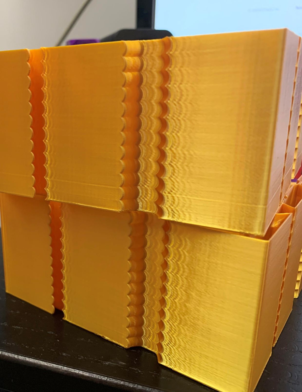
slavedas
on 26 Aug 2020
Just run the tuning tower with shaper it will run from like 31 to 75 if you
use 50 hz with the formula in guide.
On Tue, Aug 25, 2020, 9:27 PM slavedas notifications@github.com wrote:
I'm pulling my hair out on this. I've run many many test. On my Ender 3,
Input shaping worked reasonably well, it didn't get rid of ALL the ringing,
but it notably reduced it.On my CoreXY which (a model other people have successfully tuned), my
ringing is nearly input shaping AND acceleration invariant. I had
previously had good results with s-curve accel but hoped to keep my full
print speed. Yes there is some under extrusion here, but it is the same as
every other test I've run regardless. The one on top was with shaping on
BTW.Can anyone think of an obvious stupid mistake I might have made?
[image: ringing_no_result_smaller]
https://user-images.githubusercontent.com/25697200/91244111-85033500-e719-11ea-8bd3-893158849dc5.jpg—
You are receiving this because you were mentioned.
Reply to this email directly, view it on GitHub
https://github.com/KevinOConnor/klipper/issues/3025#issuecomment-680406245,
or unsubscribe
https://github.com/notifications/unsubscribe-auth/APNYI6GXIXRIX5XY2EXGXDTSCRQIRANCNFSM4OKGVTIA
.
robthide37
on 26 Aug 2020
@slavedas, please first check if there is play anywhere in the printer: e.g. if the belts are loose, maybe some screws are not tightened, etc. Given that the ringing does not depend on the accel (it should!), it means that there is a different unrelated problem either in the printer, or in your config. Maybe also check that you didn't change square_corner_velocity parameter. It is also a good idea to attach the klippy.log - it has your active configuration - and the resonance frequencies that you have measured so far.
If that does not help, you can additionally try following this section from the docs. Maybe it will help you.
dmbutyugin
on 26 Aug 2020
@dmbutyugin fair questions. I've included the log here after an experiment where I set the Y as 60% of the X (I tried both 50Hz X and 40Hz because it wasn't clear whether I was running at 80mm/s or 100mm/s during the earlier tests.) based on EddieTheEngineer's video (given the idea that 0.6 is a reasonable ratio.)
I'm seeing some interesting artifacts here that do look like they are shapers trying to compensate at further and further distances from the corners (and you can see the gap widen as the shaper smooths more and more) but there is still ringing after the corner.
Belts are both equally tight (tuned to 62Hz) and while the frame of my printer isn't particularly rigid on it's own, I have a plywood panel and added 2040 extrusion on the X and corner brackets on the 2020s on the Y. I recently realigned all my rails and replaced the belts. I just don't understand what is going on. It doesn't make sense to me that I can see ringing all the time but it's all pretty much the same. It does seem like my X rail carriage has some slop in it and it can tilt in the Y direction hard to quantify, but at the nozzle it might be as much as 1mm I think, could this be causing my issue? I don't see how this affects the X axis, though I suppose with CoreXY belts it might happen as they reverse directions and torque the carriage.
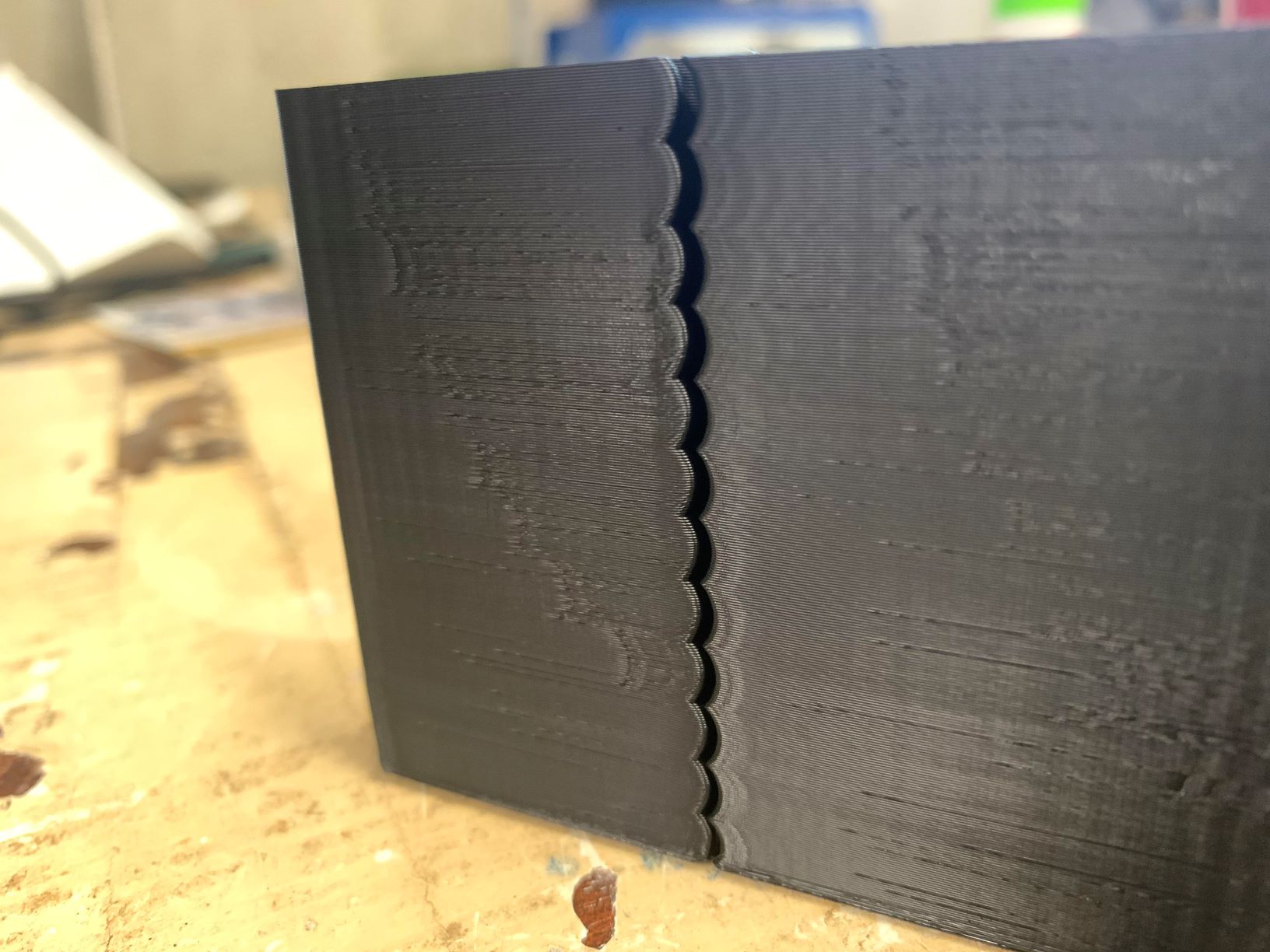 slavedas
on 26 Aug 2020
slavedas
on 26 Aug 2020
@slavedas - I don't know if it is related to your problem, but I would advice against setting stealthchop_threshold = 100. Either set stealthchop_threshold to a very low value (eg, 0) or set it to a value well above the maximum velocity for the stepper (eg, 999). Changing between stealthchop and spreadcycle modes while moving at speed will cause havoc. Also, in general, if you find that "weird things happen to the steppers", then I recommend disabling stealthchop entirely (stealhchop_threshold=0) and verify the problem still occurs with spreadcycle.
-Kevin
KevinOConnor
on 26 Aug 2020
Let me give that a try. I'll set it to 0 and see if that helps. 100 would
put it right on the threshold.
Thanks,
Steve
On Wed, Aug 26, 2020 at 2:00 PM KevinOConnor notifications@github.com
wrote:
@slavedas https://github.com/slavedas - I don't know if it is related
to your problem, but I would advice against setting stealthchop_threshold
= 100. Either set stealthchop_threshold to a very low value (eg, 0) or
set it to a value well above the maximum velocity for the stepper (eg,
999). Changing between stealthchop and spreadcycle modes while moving at
speed will cause havoc. Also, in general, if you find that "weird things
happen to the steppers", then I recommend disabling stealthchop entirely
(stealhchop_threshold=0) and verify the problem still occurs with
spreadcycle.-Kevin
—
You are receiving this because you were mentioned.
Reply to this email directly, view it on GitHub
https://github.com/KevinOConnor/klipper/issues/3025#issuecomment-681034916,
or unsubscribe
https://github.com/notifications/unsubscribe-auth/AGEBXMBSPQBINVY73VWNC4LSCVEUHANCNFSM4OKGVTIA
.
slavedas
on 26 Aug 2020
Okay, so I tore apart my X carriage, cleaned it, relubed it, bent a retainer to be a little tighter to the bearings, and reattached it. I also turned off Stealthchop and my printer is now the quietest it has ever been and Input Shapers FINALLY worked! (it's a HUGE drop in noise level, which going to Spreadcycle shouldn't do, so I'm going to assume it was the carriage). Thank you for your help.
I am going to run another attempt with threshold set to 999 to see if there is any difference (also Y resonance was lower than expected by ratio and there are faint ghosts of resonance so I'm going to try 0.6 ratio resonance as well).
slavedas
on 26 Aug 2020
@slavedas OK, it is good that you've made a progress!
I just don't understand your logic about ratios ("Y resonance was lower than expected by ratio"). There is no expectation about any ratio between the X and Y resonance frequencies (e.g. 0.6 or other ratio). I mean, maybe for some kinematics there are some reasonable assumptions that the ratio should be in a certain range (so one can use that assumption to run some sanity checks of the measurement results), but the precision of that assumption is very insufficient to actually put that value into the config.
Instead, you should reprint the test model after you fixed X carriage, measure the resonance frequencies as suggested by the doc, and just put these resonance frequencies to your config as-is. If, after that, you still see some ringing, you can try to follow this part of the guide instead. Another possibility is to get an accelerometer and measure the resonance frequencies more accurately.
dmbutyugin
on 26 Aug 2020
The logic is due to the relative weights of X carriage vs Y axis and
carriage on a CoreXY.
On Wed, Aug 26, 2020 at 5:16 PM Dmitry Butyugin notifications@github.com
wrote:
>
>
@slavedas https://github.com/slavedas OK, it is good that you've made a
progress!I just don't understand your logic about ratios ("Y resonance was lower
than expected by ratio"). There is no expectation about any ratio between
the X and Y resonance frequencies (e.g. 0.6 or other ratio). I mean, maybe
for some kinematics there are some reasonable assumptions that the ratio
should be in a certain range (so one can use that assumption to run some
sanity checks of the measurement results), but the precision of that
assumption is very insufficient to actually put that value into the config.Instead, you should reprint the test model after you fixed X carriage,
measure the resonance frequencies as suggested by the doc, and just put
these resonance frequencies to your config as-is. If, after that, you still
see some ringing, you can try to follow this
https://github.com/KevinOConnor/klipper/blob/master/docs/Resonance_Compensation.md#unreliable-measurements-of-ringing-frequencies
part of the guide instead. Another possibility is to get an accelerometer
and measure the resonance frequencies more accurately.—
You are receiving this because you were mentioned.
Reply to this email directly, view it on GitHub
https://github.com/KevinOConnor/klipper/issues/3025#issuecomment-681128542,
or unsubscribe
https://github.com/notifications/unsubscribe-auth/AGEBXMBQEOLAL26QD2XRLTTSCV3UXANCNFSM4OKGVTIA
.
slavedas
on 26 Aug 2020
Besides mass, there is also belt tension involved. And it can be relatively complicated on CoreXY. It still may be possible to estimate more precisely the ratio for each individual printer model - if the masses are known more or less exactly. But I would still consider this a sanity check and wouldn't just put the value shaper_freq_y = 0.6 * shaper_freq_x without measurements - that estimated value may be too imprecise for input_shaper.
dmbutyugin
on 26 Aug 2020
@Fenixin, in the other thread you mentioned that you have ~33 Hz resonance frequency, and you did try EI shaper. Did you happen to observe an effect like described in this comment - the gaps between the infill and perimeters? If no, which slicer do you use and which line width vs the nozzle diameter?
@dmbutyugin, It's probably too late but just in case here is an answer. I recently printed a few pieces and everything looks perfect. I updated to master branch with exactly the same values for the shaper. I didn't have any problem at all. I used PrusaSlicer, with 0.4mm nozzle and a 0.45mm line width. All the last prints were printed nice and slow, around 45-60 mm/s.
Fenixin
on 27 Aug 2020
Just to follow up on https://github.com/KevinOConnor/klipper/issues/3025#issuecomment-678459684 - I did run a test with 3 walls (bottom is without input_shaper, top is 2hump_ei/40hz - both have PA enabled):
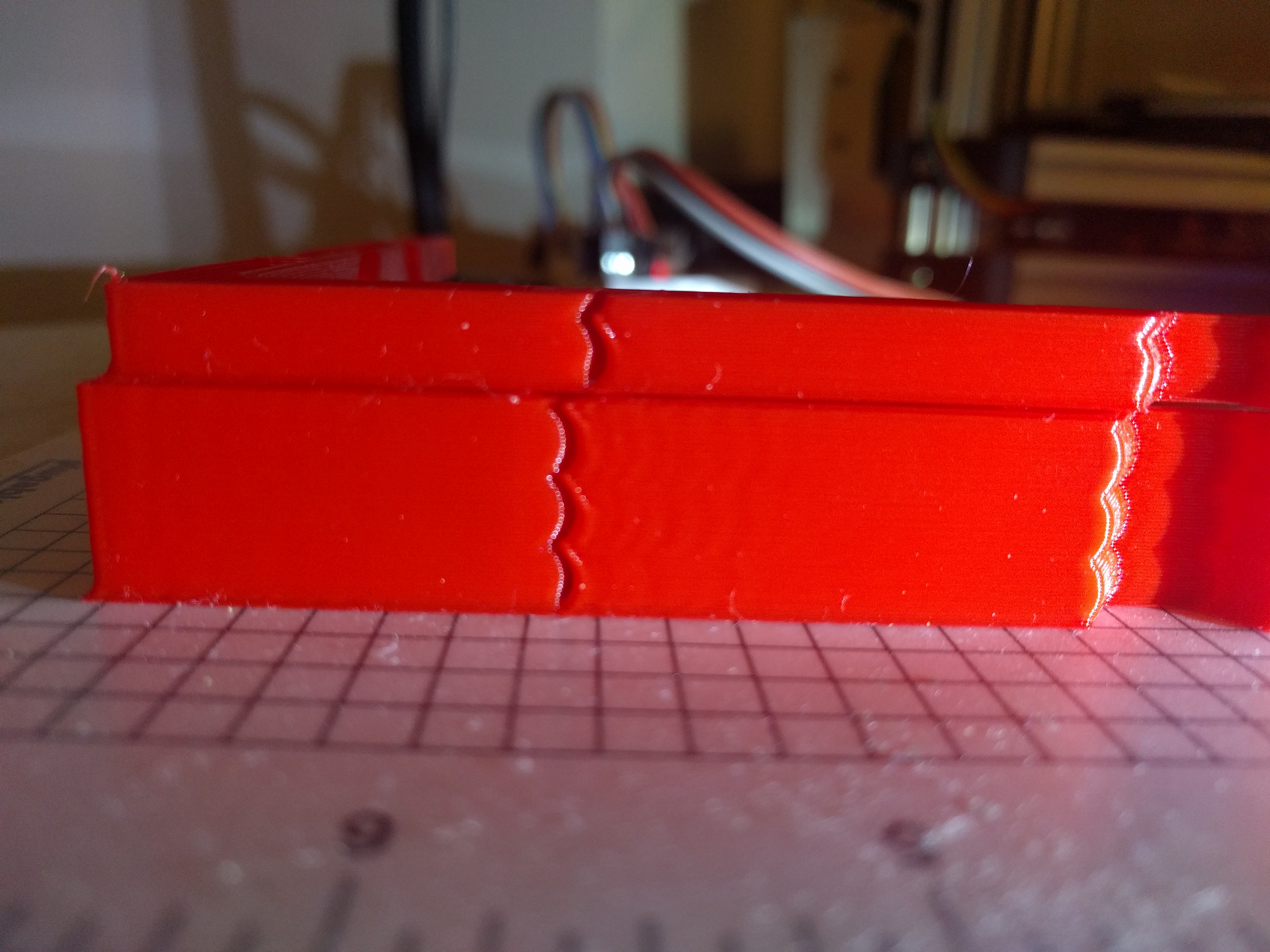
The print without input_shaper does look better, but the gap is still notably larger than it should be.
I think the nozzle may have some "play" in it, causing it to move slightly when cornering. (It's an old nozzle with a peek insulator, and it also may not have the most rigid mounting.) Not sure why input_shaper would be noticeably worse, but ultimately I think this is a printer hardware flaw and probably not directly related to input_shaper.
-Kevin
KevinOConnor
on 1 Sep 2020
I have been following this development for some time and finally managed to do some testing. The results were very pleasing. Although some ringing does remain these prints were done under fairly extreme conditions for me, so for general use I expect the result will be excellent :-)
I am testing this on a home-built Hypercube Evolution which is a CoreXY printer.
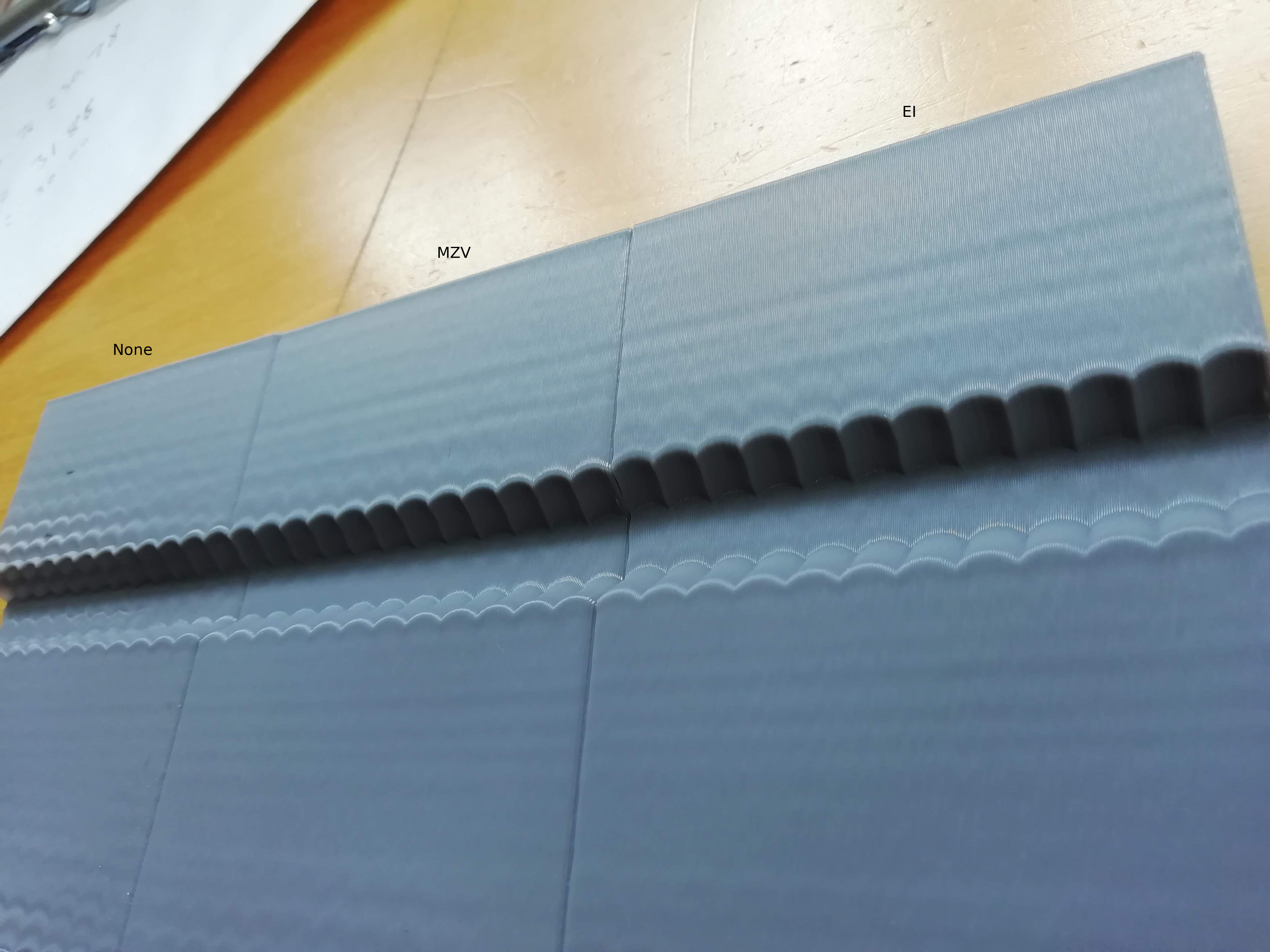
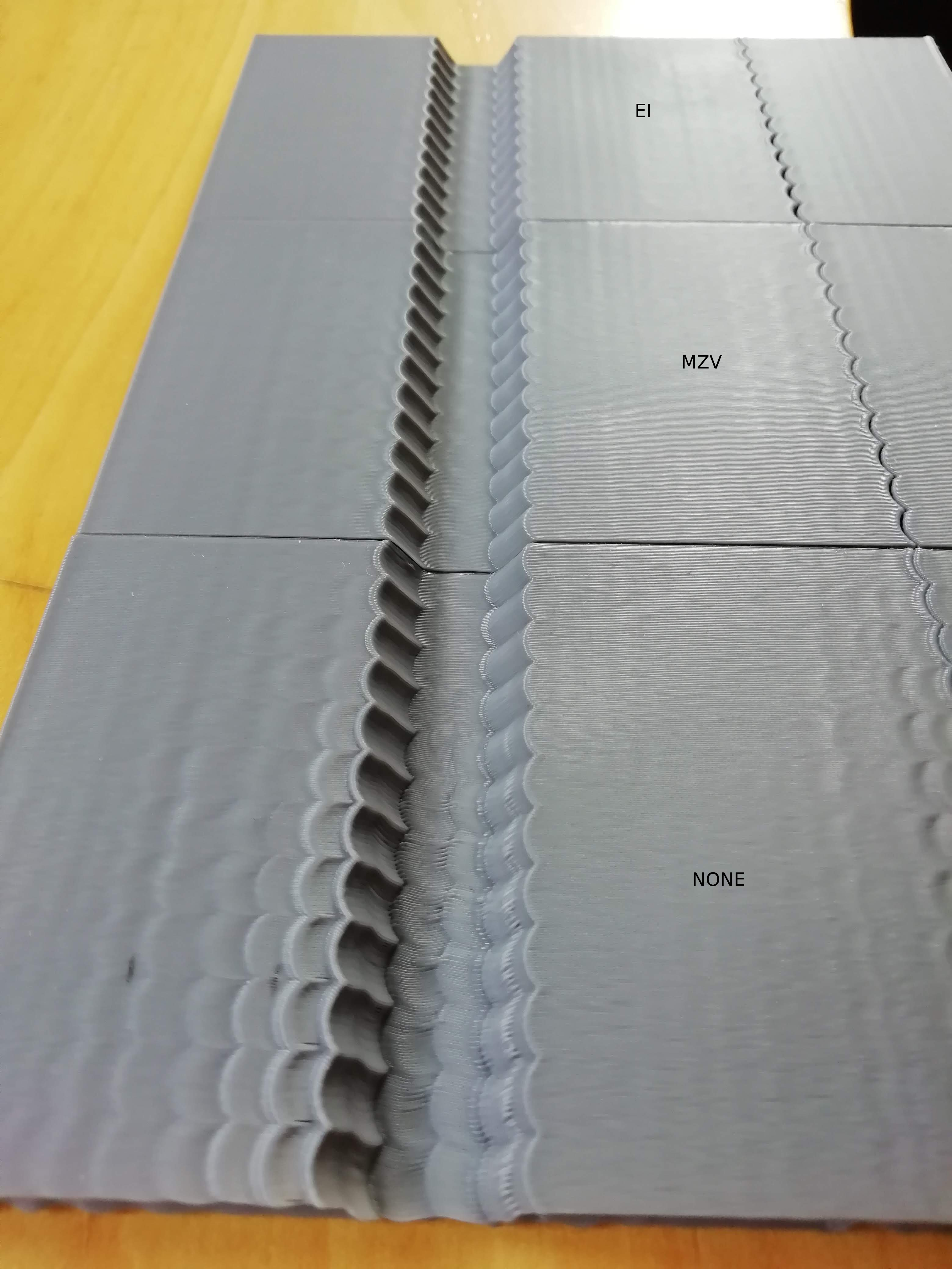
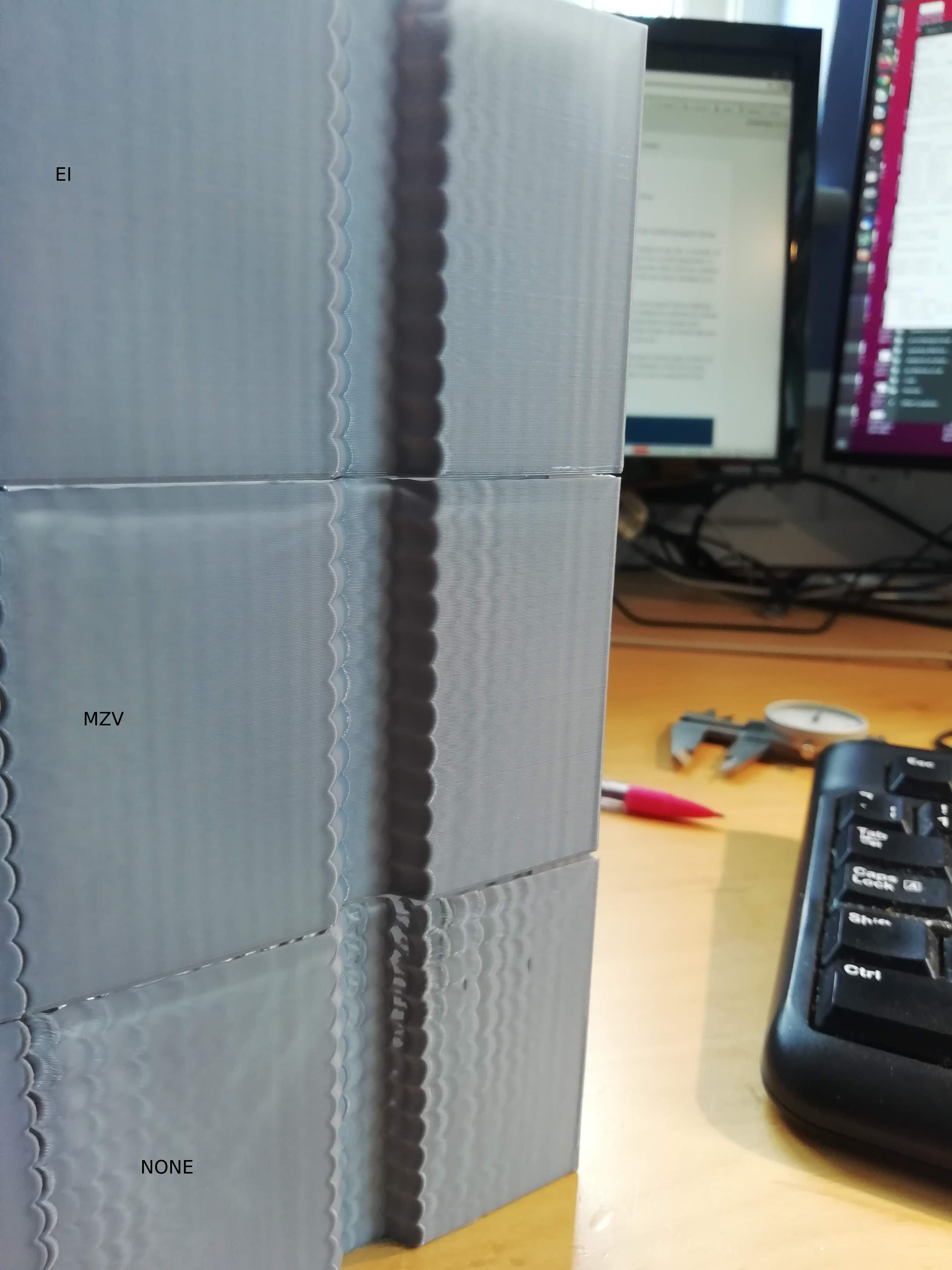
I printed the test piece using PrusaSlic3r 2.2 in spiral-vase mode at 90mm/s using pla. I measured the frequency and then tried the MZV, EI and ZV input shapers - I found the EI shaper to perform the best although it might be hard to tell from the images. Max Acceleration looks fine for around 3000 - 3500mm/s. The measured frequencies were 31.9Hz for X and 30.0Hz for Y.
Thanks.
 theopensourcerer
on 4 Sep 2020
theopensourcerer
on 4 Sep 2020
Just to follow up on #3025 (comment) - I did run a test with 3 walls (bottom is without input_shaper, top is 2hump_ei/40hz - both have PA enabled):
The print without input_shaper does look better, but the gap is still notably larger than it should be.
I think the nozzle may have some "play" in it, causing it to move slightly when cornering. (It's an old nozzle with a peek insulator, and it also may not have the most rigid mounting.) Not sure why input_shaper would be noticeably worse, but ultimately I think this is a printer hardware flaw and probably not directly related to input_shaper.
-Kevin
I had a similar artifact at higher speeds and thought it was a cooling issue but now i wonder if it was just me hitting speed with play on my carriage or something i am going to test further
robthide37
on 30 Oct 2020
I have good success using input shaper on a lightly modified Ender3. I followed along the guide. The only feedback on the guide is, that it should tell earlier to set square corner velocity to 5 (had mine cranked up before). The manual calibration worked well, ringing was easily measureable on the test print with calipers. The test print in vase mode prints quick with little filament usage.
I think input shaper is a very significant upgrade to my 3d printer! I printed at 3000mm/s² before (with some acceptable ringing), and after the test prints, I'm fine running at 7000mm/s² with nearly no ringing at all. I'm using MZV shaper, did not try the others as the results are good. No problem with rounding at all. Frequencies are 50.53 on X and 44.53 on Y.
Thanks again for this awesome contribution to Klipper!
 yschroeder
on 2 Nov 2020
yschroeder
on 2 Nov 2020
I am curious i saw that the guide mentions a sensor on the mcu as the
second one. Is it possible to install the first one on the mcu and nothing
on the rpi ?
On Mon, Nov 2, 2020, 9:19 AM Yannic Schröder notifications@github.com
wrote:
I have good success using input shaper on a lightly modified Ender3. I
followed along the guide. The only feedback on the guide is, that it should
tell earlier to set square corner velocity to 5 (had mine cranked up
before). The manual calibration worked well, ringing was easily measureable
on the test print with calipers. The test print in vase mode prints quick
with little filament usage.I think input shaper is a very significant upgrade to my 3d printer! I
printed at 3000mm/s² before (with some acceptable ringing), and after the
test prints, I'm fine running at 7000mm/s² with nearly no ringing at all.
I'm using MZV shaper, did not try the others as the results are good. No
problem with rounding at all. Frequencies are 50.53 on X and 44.53 on Y.Thanks again for this awesome contribution to Klipper!
—
You are receiving this because you were mentioned.
Reply to this email directly, view it on GitHub
https://github.com/KevinOConnor/klipper/issues/3025#issuecomment-720500012,
or unsubscribe
https://github.com/notifications/unsubscribe-auth/APNYI6CYEDTHIDZZ3LUG3H3SN25YNANCNFSM4OKGVTIA
.
robthide37
on 17 Nov 2020
@dmbutyugin So I tried the scurve branch after fine-tuning the input shaper, and even though enabling scurve with a low acceleration of 1000 did reduce the banding oh so slightly, it had less of an effect than dropping acceleration from 3000 to 2000, and slowed the print down more.
(The print was a simple test cube, so not really properly indicative of a regular/real print).
I wonder if the benefit of scurve would be more noticeable if one had better control circuitly? I have a 16Mhz AVR with A4988 steppers + 8-diode smoothers. I mean the smoothers could end up emoving the fine control?
 grigi
on 18 Nov 2020
grigi
on 18 Nov 2020
@robthide37 Yes, it is possible to connect adxl345 to the mcu (if the board has SPI connection).
dmbutyugin
on 18 Nov 2020
@grigi You should enable scurve together with input shaper, and you won't need to drop the acceleration. You can post your configs here if I misunderstood you (i.e. config with input shaper tuned, and with scurve that you've tried), maybe I can suggest something.
dmbutyugin
on 18 Nov 2020
@dmbutyugin I did have both enabled at the same time, at least I think so?
Here is my config:
printer.cfg.zip
Looking at it I see I used = instead of : for some parameters... I wonder if that makes a difference? Klipper didn't complain.
It seems klipper uses ConfigParser and that defaults delimiters, default value: ('=', ':') so I think it's not a problem.
Basically enabling [scurve] had no discernible effect in print quality, but slowed down the print?
Should I up the acceleration to a much higher value to see the benefit?
As you can see here, the top is without scurve, bottom with scurve. Only difference is the scurve block.
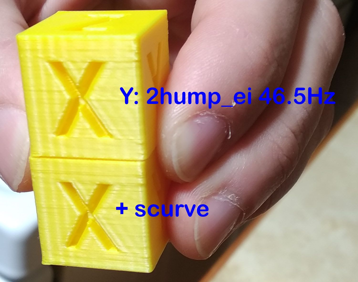
This is at 3000mm/s² acceleration as is specified in that config file.
Top one printed in ~14:20 minutes, bottom one in ~15:30 minutes.
grigi
on 19 Nov 2020
@dmbutyugin I think I figured out how to get the benefit of scurve.
I got almost no perceptible ringing now using scurve:
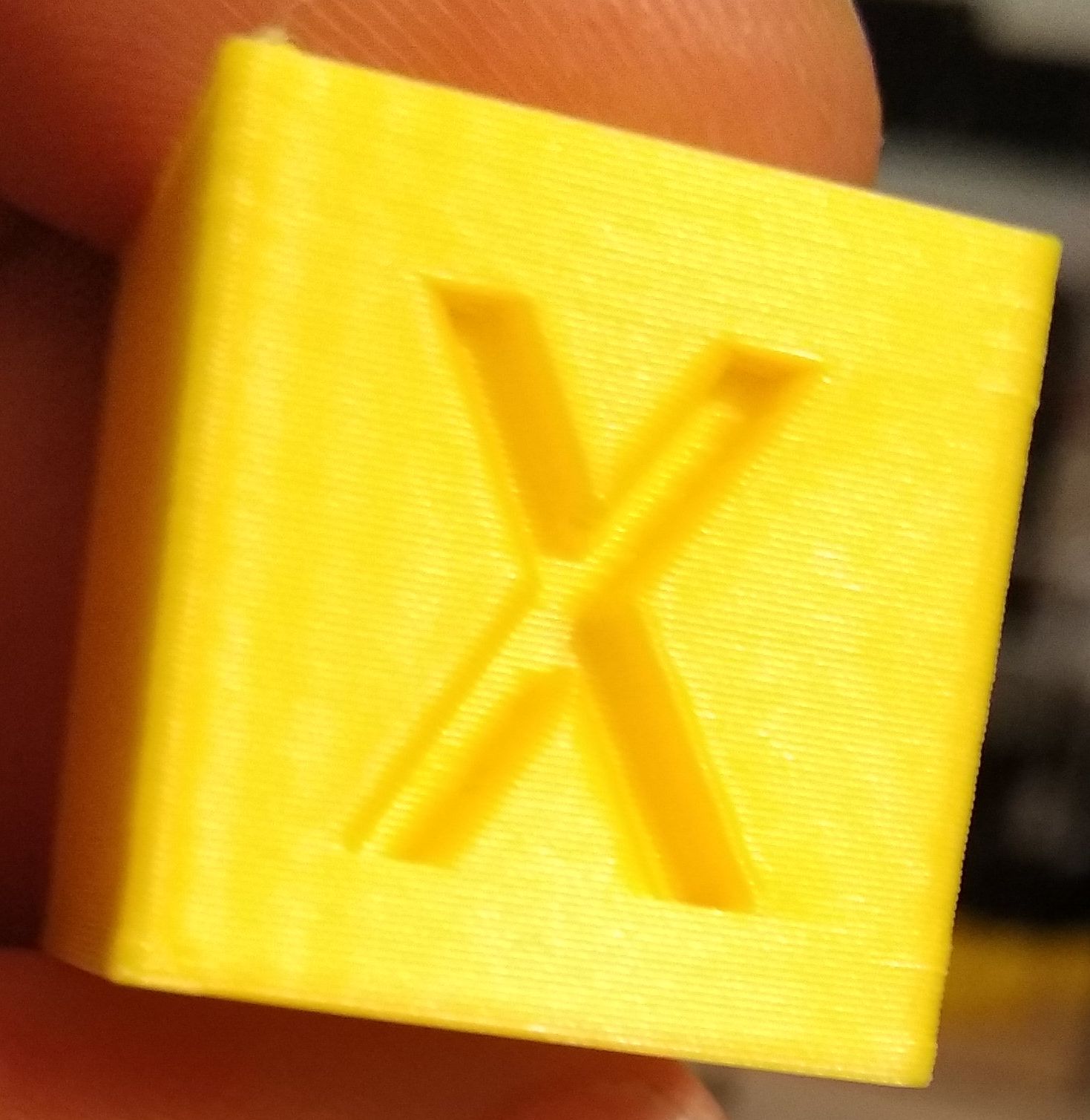
Also, edges are much sharper now too. I think it's because you slow down around the corners?
What I needed to do was to reduce the min_accel to where there is absolutely NO ringing. Which for me was 600mm/s².
I then bumped max_accel to 5000mm/s², but I think due to the small print it didn't really get there.
The print took 16 minutes now, so slower, but significantly better, and still faster than running at 600mm/s² max_accel. About how fast a 1500mm/s² max_accel print would be.
Note that X-gantry ringing was easy to resolve. The Y-gantry ringing with its entire slinging bed required much more intensive interventions.
Could you please add to your docs:
- If you don't see a noticeable drop in ringing, to drop the
min_accel - Heavy bed slinging printers may need a greater reduction in
min_accelto get properly rid of ringing. - The smoothing effect of Resonance Compensation will lessen with a lower
min_accel - It may be worth it to bump the
max_accelto re-gain some of the print-time penalty
grigi
on 19 Nov 2020
Hi, I'm trying to update to scurve shaping branch cause it's been a while I havent ... I am on branch "scurve-smoothing", and I have enabled Scurve both to reduce ringing, but also to allow my BMG bowden extruder to not die because of massive (jerk) movements.
so I have in my config :
[smooth_axis]
smooth_x: 0.017094017 # a * 2 / 3
smooth_y: 0.017094017 # a * 2 / 3
accel_comp_x: 0.000015
accel_comp_y: 0.000015
[scurve]
acceleration_order: 4
min_jerk_limit_time: 0.025641026
my question is : now, what has replaced the "min_jerk_limit_time" ? Because I think that it's the one that keeps my extruder driver from screaming to death.
second question : is s-curve the only difference now between this branch and Kevin's master branch ?
 aschor
on 30 Nov 2020
aschor
on 30 Nov 2020
@aschor
second question : is s-curve the only difference now between this branch and Kevin's master branch ?
Yes, that's the only difference for scurve-shaping branch.
my question is : now, what has replaced the "min_jerk_limit_time" ? Because I think that it's the one that keeps my extruder driver from screaming to death.
So, [smooth_axis] is now replaced with [input_shaper] with appropriate parameters. [scurve] stays in principle, but I no longer advice to change min_jerk_limit_time. Previously you could configure max_jerk and now I suggest to change/adjust min_accel parameter.
dmbutyugin
on 1 Dec 2020
hummm @dmbutyugin I've a "little" issue .....
git reset --hard
git status
On branch scurve-shaping
Your branch is up to date with 's-curve-exp/scurve-shaping'.

nothing to commit, working tree clean
... and yet :
Sending MCU 'mcu' printer configuration...
Configured MCU 'mcu' (1024 moves)
Sending MCU 'rpi' printer configuration...
Configured MCU 'rpi' (1024 moves)
Starting heater checks for heater_bed
Unhandled exception during connect
Traceback (most recent call last):
  File "/home/pi/klipper/klippy/klippy.py", line 151, in _connect
    cb()
  File "/home/pi/klipper.20201201/klippy/extras/scurve.py", line 127, in connect
    new_move_queue = AccelCombiningMoveQueue(self, self.toolhead)
  File "/home/pi/klipper.20201201/klippy/extras/scurve.py", line 18, in __init__
    old_queue = toolhead.get_move_queue()
AttributeError: ToolHead instance has no attribute 'get_move_queue'
I just activated S-curve to test it .... If I disable the "scurve" config section, klipper starts happily :/
aschor
on 8 Dec 2020
I had a similar issue, which was because the SD card of my RPi was corrupting itself. The proper solution was a new SD card :-(
Seems like its a bad idea to use an SD card that was punished in a phone for a few years.
grigi
on 8 Dec 2020
I had a similar issue, which was because the SD card of my RPi was corrupting itself. The proper solution was a new SD card :-(
Seems like its a bad idea to use an SD card that was punished in a phone for a few years.
hummm I happen to run from an SSD.
Seems that when I did "git checkout", maybe I did not stop/start klipper service. I grep'ed the file and the definition is there. Restarting after checking out master branch does trigger a C compilation.
.... but klipper does not work going from master to scurve-shaping, because it triggers a Unknown command: schedule_soft_pwm_out ....... wich is quite unfortunate because I just had a similar message going to master, and I have re-compiled firmware and uploaded to mcu 1 hour ago. So I guess that I am now going to recompile it again on scurbe-branch and see if it works here this time ... stay tuned (I'll update this post)
edit : it works (again) with scurve activated
aschor
on 8 Dec 2020
Seems that when I did "git checkout", maybe I did not stop/start klipper service. I grep'ed the file and the definition is there. Restarting after checking out master branch does trigger a C compilation.
Restarting Klipper is very important if git manipulation is done with the installation (or any manipulation with the source code for that matter).
.... but klipper does not work going from master to scurve-shaping, because it triggers a
Unknown command: schedule_soft_pwm_out
FWIW, I synced the scurve-shaping branch to master. There were probably some changes in the mainline Klipper recently that added a new mcu comment.
dmbutyugin
on 8 Dec 2020
Hi @dmbutyugin . Figured I'd provide some high-level observations on input shaper:
- The docs/Resonance_Compensation.md file currently states
**Warning**: Input Shaping support is experimental. It seems a large number of users are now running with input shaper and the feedback has been positive. What do you think about removing the experimental warning? - I've noticed that users seem to get really confused with the X and Y on the test print. I wonder if things would be simpler if we changed the labels on the test print to "A" and "B". That way, the docs could say something like "use the side with the A on it to measure the X resonance" and not have to go into the explanation of X vs Y axes.
- FYI, I saw this video of an input shaper "livestream" configuration: https://www.youtube.com/watch?v=zPgZB6TjZP4 (print comes off the machine at 1:43:00).
-Kevin
KevinOConnor
on 11 Dec 2020
Hi @KevinOConnor,
1. The docs/Resonance_Compensation.md file currently states ` **Warning**: Input Shaping support is experimental`. It seems a large number of users are now running with input shaper and the feedback has been positive. What do you think about removing the experimental warning?
I think that makes sense. I have a few minor updates / corrections to the docs, so I figure I'll just put everything together and send a PR for the docs.
2. I've noticed that users seem to get really confused with the X and Y on the test print. I wonder if things would be simpler if we changed the labels on the test print to "A" and "B". That way, the docs could say something like "use the side with the A on it to measure the X resonance" and not have to go into the explanation of X vs Y axes.
I agree that the current way could be a bit confusing for some users. Though the docs say: use measurements on the side with X mark for X axis configuration and with Y - for Y axis respectively, I think some users still get confused (and perhaps think that that's how the model should be oriented?). The only good thing about the current setup is that once you know that, you don't need docs to figure out what's what - it is self-explanatory. With A/B marks one would still need to lookup in the docs what they mean. But I do not have a very strong opinion about it, so if people would prefer it this way - I can change the model.
3. FYI, I saw this video of an input shaper "livestream" configuration: https://www.youtube.com/watch?v=zPgZB6TjZP4 (print comes off the machine at 1:43:00).
Interesting, thanks for sharing, I will certainly take a look!
dmbutyugin
on 11 Dec 2020
Related issues
KevinOConnor
·
5Comments
 TronskiFPV
·
5Comments
TronskiFPV
·
5Comments
 Hywelmartin
·
6Comments
Hywelmartin
·
6Comments
 CHILLYSMOKES
·
5Comments
CHILLYSMOKES
·
5Comments
 Michael-Bell
·
5Comments
Michael-Bell
·
5Comments
Most helpful comment
I gave this a whirl and it's amazing. There's probably still some room for optimization, but this is the most significant advancement in FDM quality I've seen in years. And it was painless to try out. Incredible.