Klipper: Rotary delta ( Delta robot kinematics )
Dear Sir,
Good day,
I am sure that you know about such kinematics as a rotating delta. But at the moment as far as I know the klipper does not support this kinematics.
Could you please add this kinematics to the klipper?
I found on the Internet some resources with kinematics calculations and examples of source code in С language.
But my knowledge of programming languages and mathematics is not enough to do this properly.
I am sure that many people will use this kinematics and will support you.
But there is a nuance, an article with calculations of kinematics in Russian. So help us Google translator.
https://habr.com/en/post/390281/
https://www.marginallyclever.com/other/samples/fk-ik-test.html
// dimensions of the robot
// (designations see on the scheme)
const float e = 115.0; // side of the movable platform
const float f = 457.3; // fixed base side
const float re = 232.0;
const float rf = 112.0;// trigonometric constants
const float sqrt3 = sqrt(3.0);
const float pi = 3.141592653; // PI
const float sin120 = sqrt3/2.0;
const float cos120 = -0.5;
const float tan60 = sqrt3;
const float sin30 = 0.5;
const float tan30 = 1/sqrt3;// direct kinematics: (theta1, theta2, theta3) -> (x0, y0, z0)
// return status: 0=OK, -1=nonexistent position
int delta_calcForward(float theta1, float theta2, float theta3, float &x0, float &y0, float &z0) {
float t = (f-e)*tan30/2;
float dtr = pi/(float)180.0;theta1 *= dtr; theta2 *= dtr; theta3 *= dtr; float y1 = -(t + rf*cos(theta1)); float z1 = -rf*sin(theta1); float y2 = (t + rf*cos(theta2))*sin30; float x2 = y2*tan60; float z2 = -rf*sin(theta2); float y3 = (t + rf*cos(theta3))*sin30; float x3 = -y3*tan60; float z3 = -rf*sin(theta3); float dnm = (y2-y1)*x3-(y3-y1)*x2; float w1 = y1*y1 + z1*z1; float w2 = x2*x2 + y2*y2 + z2*z2; float w3 = x3*x3 + y3*y3 + z3*z3; // x = (a1*z + b1)/dnm float a1 = (z2-z1)*(y3-y1)-(z3-z1)*(y2-y1); float b1 = -((w2-w1)*(y3-y1)-(w3-w1)*(y2-y1))/2.0; // y = (a2*z + b2)/dnm; float a2 = -(z2-z1)*x3+(z3-z1)*x2; float b2 = ((w2-w1)*x3 - (w3-w1)*x2)/2.0; // a*z^2 + b*z + c = 0 float a = a1*a1 + a2*a2 + dnm*dnm; float b = 2*(a1*b1 + a2*(b2-y1*dnm) - z1*dnm*dnm); float c = (b2-y1*dnm)*(b2-y1*dnm) + b1*b1 + dnm*dnm*(z1*z1 - re*re); // discriminant float d = b*b - (float)4.0*a*c; if (d < 0) return -1; // nonexistent position z0 = -(float)0.5*(b+sqrt(d))/a; x0 = (a1*z0 + b1)/dnm; y0 = (a2*z0 + b2)/dnm; return 0;}
// inverse kinematics
// auxiliary function, angle calculation theta1 (in the YZ plane )
int delta_calcAngleYZ(float x0, float y0, float z0, float &theta) {
float y1 = -0.5 * 0.57735 * f; // f/2 * tg 30
y0 -= 0.5 * 0.57735 * e; // move the center to the edge
// z = a + by
float a = (x0x0 + y0y0 + z0z0 +rfrf - rere - y1y1)/(2z0);
float b = (y1-y0)/z0;
// discriminant
float d = -(a+by1)(a+by1)+rf(bbrf+rf);
if (d < 0) return -1; // nonexistent point
float yj = (y1 - ab - sqrt(d))/(bb + 1); // choose an external point
float zj = a + byj;
theta = 180.0atan(-zj/(y1 - yj))/pi + ((yj>y1)?180.0:0.0);
return 0;
}// inverse kinematics: (x0, y0, z0) -> (theta1, theta2, theta3)
// return status: 0=OK, -1=nonexistent position
int delta_calcInverse(float x0, float y0, float z0, float &theta1, float &theta2, float &theta3) {
theta1 = theta2 = theta3 = 0;
int status = delta_calcAngleYZ(x0, y0, z0, theta1);
if (status == 0) status = delta_calcAngleYZ(x0cos120 + y0sin120, y0cos120-x0sin120, z0, theta2); // rotate coords to +120 deg
if (status == 0) status = delta_calcAngleYZ(x0cos120 - y0sin120, y0cos120+x0sin120, z0, theta3); // rotate coords to -120 deg
return status;
}
Thank you.
 mapa3m1
All 85 comments
Hi @mapa3m1,
It did not look like there was a Klipper log file attached to this ticket. The log file has been engineered to answer common questions the Klipper developers have about the software and its environment (software version, hardware type, configuration, event timing, and hundreds of other questions).
Unfortunately, too many people have opened tickets without providing the log. That consumes developer time; time that would be better spent enhancing the software. If this ticket references an event that has occurred while running the software then the Klipper log must be attached to this ticket. Otherwise, this ticket will be automatically closed in a few days.
For information on obtaining the Klipper log file see: https://github.com/KevinOConnor/klipper/blob/master/docs/Contact.md
The log can still be attached to this ticket - just add a comment and attach the log to that comment.
Best regards,
~ Your friendly GitIssueBot
PS: I'm just an automated script, not a human being.
 klipper-gitissuebot
on 5 May 2019
klipper-gitissuebot
on 5 May 2019
if anyone give it a go.. a moving bed would be awesome...
 Hywelmartin
on 14 May 2019
Hywelmartin
on 14 May 2019
FWIW, this looks like the same type of kinematics that is implemented by smoothieware. The Kinematics themselves are not hard - the difficulty is in testing it. Do you have the particular printer? Have you been able to install Klipper on it and test that basic motor functions work?
-Kevin
 KevinOConnor
on 16 May 2019
KevinOConnor
on 16 May 2019
FWIW, this looks like the same type of kinematics that is implemented by smoothieware. The Kinematics themselves are not hard - the difficulty is in testing it. Do you have the particular printer? Have you been able to install Klipper on it and test that basic motor functions work?
-Kevin
I would like to build it, spare part already shipped, i am already use klipper on my cartesian printer.
About testing that basic motor functions work - yes, but a little bit later, now i'm so far from my home.
I know that many people from the Russian-speaking community want to have a printer with such kinematics, but the problem is that there is no software for this kinematics.
There is one person who made a printer with a kinematics delta robot and uses smoothieware. https://www.thingiverse.com/AlexKorvin/about
But smoothieware has some bugs.
mapa3m1
on 17 May 2019
I'm going to mark this as inactive then as it doesn't look like anyone is currently working on an implementation for it.
-Kevin
KevinOConnor
on 25 May 2019
Hi my name is Alex Korvin
I made a Non-linear Delta 3D Printer
https://www.thingiverse.com/thing:3489886
I want to make it work with klipper
could you please port the kynematics for it from the smoothieware firmware?
https://github.com/Smoothieware/Smoothieware/blob/edge/src/modules/robot/arm_solutions/RotaryDeltaSolution.cpp
And here you can find the Marlin firmware, adapted for the delta robot. Perhaps this will help.
https://github.com/TTN-/IcePick-Delta/tree/master/Firmware
Here you can read a little about the kinematics of the delta robot.
http://forums.trossenrobotics.com/tutorials/introduction-129/delta-robot-kinematics-3276/
 A1exKorvin
on 13 Oct 2019
A1exKorvin
on 13 Oct 2019
I can help with the basic implementation of the rotary delta kinematics. However, it would require someone with the hardware to test and provide feedback.
If you're willing to do that, please start by installing klipper on the machine - use simple cartesian kinematics to start and verify that all the main functionality is working. Use the STEPPER_BUZZ command (as described in the installation and config checks documents) to verify that all the motors are working properly. Then attach the resulting klipper log file here. I will also need to know the key parameters of the machine (arm lengths, platform height, platform radius, effector radius, etc.).
-Kevin
KevinOConnor
on 15 Oct 2019
Alex thank you for reaching out if you need help. Do not hesitate to contact me. Or come over the klipper discord channel. they are some russian speakers here and there. https://discord.gg/V7Z5py
 manu7irl
on 16 Oct 2019
manu7irl
on 16 Oct 2019
I can help with the basic implementation of the rotary delta kinematics. However, it would require someone with the hardware to test and provide feedback.
If you're willing to do that, please start by installing klipper on the machine - use simple cartesian kinematics to start and verify that all the main functionality is working. Use the STEPPER_BUZZ command (as described in the installation and config checks documents) to verify that all the motors are working properly. Then attach the resulting klipper log file here. I will also need to know the key parameters of the machine (arm lengths, platform height, platform radius, effector radius, etc.).
-Kevin
Ok, thanks, I’ll definitely do it =)
A1exKorvin
on 18 Oct 2019
Alex thank you for reaching out if you need help. Do not hesitate to contact me. Or come over the klipper discord channel. they are some russian speakers here and there.
Sure, thanks =)
A1exKorvin
on 18 Oct 2019
Any further progress with this?
-Kevin
KevinOConnor
on 13 Nov 2019
It would be very interesting, I was thinking of making one but there are hardly any firmwares that control it.. I wish I could work with her together with klipper.
 maketo3D
on 17 Nov 2019
maketo3D
on 17 Nov 2019
I put together code for the rotary delta kinematics:
cd ~/klipper ; git fetch ; git checkout origin/work-rotary-20191119 ; sudo service klipper restart
This is preliminary code (hasn't been tested on real hardware; no boundary checks are implemented). If anyone tests this, please report your findings (success or failure).
-Kevin
KevinOConnor
on 20 Nov 2019
I put together code for the rotary delta kinematics:
cd ~/klipper ; git fetch ; git checkout origin/work-rotary-20191119 ; sudo service klipper restart
This is preliminary code (hasn't been tested on real hardware; no boundary checks are implemented). If anyone tests this, please report your findings (success or failure).
-Kevin
Hi. Sorry for the long reply. I am currently busy with ongoing projects and there is no time to conduct tests yet. I will ask for help with this guys who already have a assembled robot =)
A1exKorvin
on 20 Nov 2019
Hi Kevin !
Please see requested files. I have a chance only to test XYZ motors and endstops.
They are working correct. I can not say it was exactly 1mm, but seems so.
Hope it will help. I am ready to send you any additional information if I missed something.
Regards,
Vlad.
 vladT0
on 25 Nov 2019
vladT0
on 25 Nov 2019
Great. The next step is to pull down the developer branch with the rotary delta code:
cd ~/klipper ; git fetch ; git checkout origin/work-rotary-20191119 ; sudo service klipper restart
Then you'll need to update your config based on the example given in config/example-rotary-delta.cfg . Let me know if you have questions about the config.
-Kevin
KevinOConnor
on 25 Nov 2019
Interesting...
Would it be difficult to add a z-axis to overcome that limitation.. I think it would be an interesting idea for normal deltas as well..
Hywelmartin
on 27 Nov 2019
@KevinOConnor
Hi Kevin !
Thanks a lot for your very fast response.
I followed your instructions, but seems made something wrong.
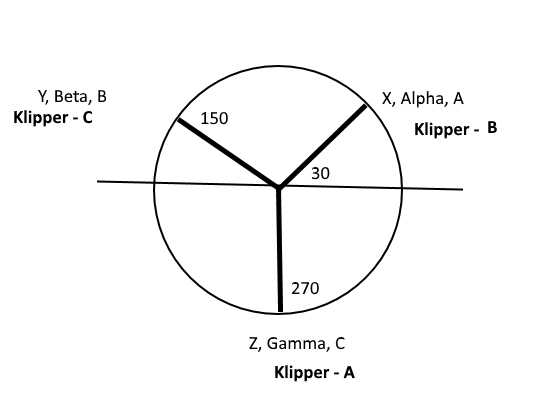
1) Please see attached pic with typical delta arms IDs. I am a little bit confused. According your
comments in example config file, you have other IDs for arms. I show it in bold font with word
Klipper. Usually IDs named counterclock-wise.
2) I am not sure, I calculated correctly step_distance.
For Smoothie it was:
LV8729 driver set for 128 microsteps = (200 x 128 x 26.01)/360 = 1805
Klipper: I take formula from your comments and just added reduction 26.01
2x3.1415x26.01x1.8/360/128 = 0.0063836262
First time I calculate it as
1/1805 = 0.000554
3) G28 command is not working. See logs.
Thanks in advance for your help.
Vlad.
vladT0
on 27 Nov 2019
Yes, I think your arm diagram is correct. We can change Klipper to match Smoothie, but lets leave it like this until we get it working.
If there is a 26.01 gearing ratio on a 1.8 degree stepper with a 128 microsteps, then you would use 2 * pi * (1.8 / 360) / 128 / 26.01 == 0.000009436252444. (This is also quirky and should be changed in Klipper, but lets see if it works first.)
(200 x 128 x 26.01)/360 = 1805
FYI, (200 * 128 * 26.01)/360 = 1849.6 - I'm not sure if that was a typo or if you have a different gearing ratio.
-Kevin
KevinOConnor
on 28 Nov 2019
Hi Kevin !
It was mistake, I have to divide by gearing ratio :)
Correct figures for me are:
2 * pi * (1.8 / 360) / 128 / 25.3835 = 0.00000966886708
(200 x 128 x 25.3835)/360 = 1805
I will check today, I see only one problem, according comments in config, I have to use just 6 digits,
in this case I can take 0.000009 and you will lose precision in calculation.
Regards,
Vlad.
vladT0
on 28 Nov 2019
according comments in config, I have to use just 6 digits,
For a rotary delta, I'd use 15 digits.
-Kevin
KevinOConnor
on 28 Nov 2019
Just for my knowledge, what gearing are you using for the steppers? Is it a two gear system (small gear on the stepper and large gear on the shoulder joint)? If so, what's the tooth count and belt size (eg GT2) on each of the pulleys?
-Kevin
KevinOConnor
on 28 Nov 2019
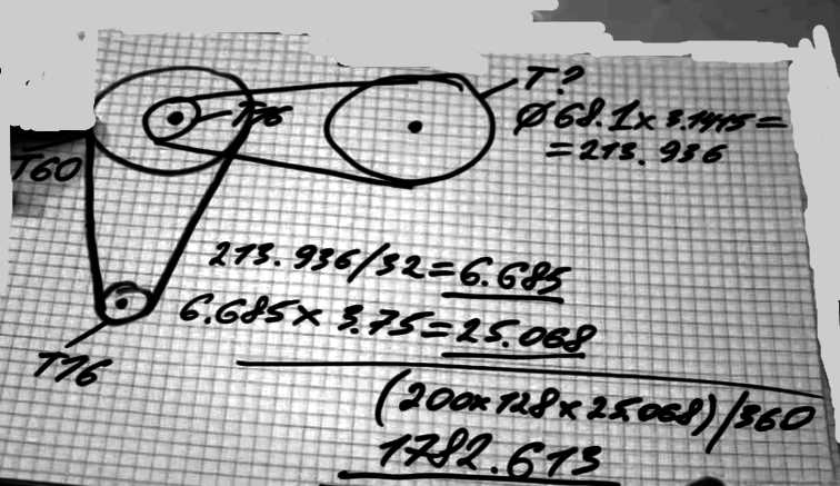
I attached here screenshot from Alex's video.
About gearing ratio: can I use 15 digits right now or it will be in the next versions ?
vladT0
on 28 Nov 2019
can I use 15 digits right now or it will be in the next versions ?
Use 15 digits with the current code.
-Kevin
KevinOConnor
on 28 Nov 2019
Hi Kevin !
Please see attached files. With this config motors are not working. After command STEPPER_BUZZ STEPPER=stepper_a firmware crashed. I think you see this event in the log. I can reload it only with Reset button on printer controller. Microcode ( firmware) was re-flashed too.
klippy.log
printer.txt
Regards,
Vlad.
vladT0
on 28 Nov 2019
There was an error in the Klipper code related to step_distance being in radians (vs the normal millimeters) which caused both the endstop checking and stepper_buzz code to produce incorrect timing. I've put together a workaround on the work-rotary-20191119 branch:
cd ~/klipper ; git fetch ; git checkout origin/work-rotary-20191119 ; sudo service klipper restart
-Kevin
KevinOConnor
on 29 Nov 2019
Thanks for the diagram. I'm still a little confused on the gearing ratio. The diagram seems to show a 60:16 gear driving a 107:16 gear, which results in a 25.078125 gearing ratio (60*107 / (16*16) = 25.078125). (I'm guessing the 25.068 is different just due to rounding differences.)
You're reporting a 25.3835 gearing ratio, however. Do you have a 60:16 gear followed by a 108:16 gear (for a gearing ratio of 60*108 / (16*16) = 25.3125)?
Or, does the final pulley not have teeth (or not have a whole number of teeth)?
Also, what type of host machine are you running the Klipper software on?
Cheers,
-Kevin
KevinOConnor
on 29 Nov 2019
Hi Kevin !
I will install right now new version and test it.
About gearing ratio:
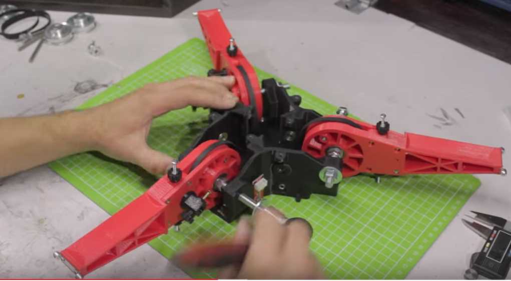
I think from this screenshot, from Alex's video, will be clear. Yes, you are right, final pulley
1) Printed
2) Without teeth.
I have a little bit other size of pulley.
Host is Raspbery Pi (the first version ).
vladT0
on 29 Nov 2019
#The steps per degree are calculated as:
#  For Firepick delta robot:
# (1) First determine the circumference of the big pulley, which has a smooth surface, and calculate the 'teeth it would have'
# (2) Determine the GT2 belt thickness and tooth depth
# (3) Calculate the ACTUAL big pulley circumference taking into account that the GT2 belt affects this as
#     it rests on the big pulley and not into teeth cut into the pulley, the formula is:
#     BIG_PULLEY_CIRCUMFERENCE = BIG_PULLEY_TEETH * TOOTH_SPACING + (BELT_THICKNESS - TOOTH_DEPTH)*6.283185
# (4) Calculate the ACTUAL small pulley circumference taking into account that the GT2 belt affects this as
#     rests into the small pulley as it has teeth cut into the pulley, the formula is:
#     SMALL_PULLEY_CIRCUMFERENCE = SMALL_PULLEY_TEETH * TOOTH_SPACING
# (5) Now determine the pulley reduction which is:
#     PULLEY_REDUCTION = BIG_PULLEY_CIRCUMFERENCE / SMALL_PULLEY_CIRCUMFERENCE
# (6) Finally, given the number of steps a stepper motor needs for a full 360 degree rotation, and the number of microsteps your
#     stepper motor driver chip is set for, you can calculate the STEPS_PER_MM for each axis, which for a Rotary Delta, are the same:
#    [ALPHA/BETA/GAMMA]_STEPS_PER_MM = (XYZ_STEPS_PER_ROTATION*XYZ_MICROSTEPS*PULLEY_REDUCTION)/360
Hi Kevin !
Nothing fetched for me. All files are the same.
work-rotary-20191119 - is it correct branch ?
Regards,
Vlad.
vladT0
on 29 Nov 2019
Oops. Forgot to push. Should be up now. Also, note that STEPPER_BUZZ should move the shoulder joint back and forth 1 radian instead of 1mm.
-Kevin
KevinOConnor
on 29 Nov 2019
Hi Kevin !
G28 was working to the wrong direction. I inverted DIR pins and seems G28 is working correctly now. Homing_retract is not tune-able and executed with the same speed. I would start retract much slower. It helps to find more precision home position.
So I executed G28, check positions with M114 and tried G0 Z200 and
mcu crashed again. See log. Please advice, what to execute for the next tests.
Regards,
Vlad.
klippy.log
printer.txt
vladT0
on 29 Nov 2019
The second home should occur at half the homing speed - it can be tuned via the second_homing_speed parameter (see config/example.cfg).
My first impression of the error is that the rpi1 got overloaded (looks like it took 400ms to produce the first 500ms worth of steps and that caused the micro-controller to trigger an error). Klipper is better on an rpi2 (or faster) host machine. That said, generating a z-only move while the head is near the top of the frame requires the most work. You could try first moving the head down with a slow move (eg, G0 Z100 F300), to see if moving out of that trouble zone improves your results.
Otherwise, I'll try to take a closer look at the error over the next couple of days.
-Kevin
KevinOConnor
on 30 Nov 2019
Hi Kevin !
You was completely right. It was issue with host. F300 options solved issue. I will change the host next week to the new one, version 3 or 4. Is Zero faster ? I have it at home too.
Very good news, distance of the Z moving is very closer to the real mm size, I measured it. I never could get this result with Smoothie, don't know why, but it is other story.
Could I test something also with Pi1 host ? or shall I wait before you improve source code for the delta ?
Minor bug, second homing speed was not recognized. See log file.
Regards,
Vlad.
klippy.log
printer.txt
vladT0
on 30 Nov 2019
Is Zero faster ?
I don't think it is faster. (Or, only slightly faster.)
Could I test something also with Pi1 host ?
Do X and Y moves work properly? As long as you avoid fast Z only moves, I suspect the pi1 will work okay. You could also go to 16 microsteps on the stepper drivers to reduce the load. Finally, you could try changing the MOVE_BATCH_TIME = 0.500 in klippy/toolhead.py to MOVE_BATCH_TIME = 0.200. (If changing the host source code, be sure to do a sudo service klipper restart after every change.)
Minor bug, second homing speed was not recognized.
Looks like a colon was missing in the config file - it should be: second_homing_speed: 10
-Kevin
KevinOConnor
on 30 Nov 2019
1) About MOVE_BATCH_TIME - what is sense of this param ? Is time affected on communication between host and microcode kernel ?
2) I have tmc2208, they are working in simple mode as 1/16, but I noticed Klipper supported special modes for it, can I test it with Rotary delta or it is not implemented right now ?
vladT0
on 30 Nov 2019
MOVE_BATCH_TIME is an internal accounting setting. It controls how many steps the host may generate before flushing them to the micro-controller. It doesn't alter the robot behaviour.
The tmc2208 needs to be have the UART line wired up and [tcm2208 stepper_a] type sections added to the config. Otherwise, it should work fine.
-Kevin
KevinOConnor
on 30 Nov 2019
Good evening Kevin !
I changed MOVE_BATCH_TIME = 0.200 and now G0 command is working with usual speed and did not crash. X and Y are working correct too. Unfortunately second_homing_speed: 10 has no affect on speed. I expect homing_retract_dist: 10.0 moves back very slowly. 10mm or 10 radian ?
Regards,
Vlad.
vladT0
on 1 Dec 2019
The tmc2208 needs to be have the UART line wired up and
[tcm2208 stepper_a]type sections added to the config. Otherwise, it should work fine
Hi Kevin !
I have tried to use TMC2208 V2.0, what I did step by step:
1) Recalculate step per radiant according 1/16.
2) Solder pad for all drivers.
3) Removed all jumper caps under the driver.
4) Put jumper caps to the XUART, YUART, ZUART.
5) Configure UART section for each stepper. Here I was a little bit confused, what pin to use, RX or TX, but seems according example with SKR board was used RX pin.
6) According board documentation, if pad is soldered, I don't need any additional wire.
If using the TMC2208 V2.0 version, you don’t need to connect NC and uart on the driver.
Service was restarted, but klipper can not communicate with UART pin, See log.
Error: Unable to read tmc uart 'stepper_b' register IFCNT
Please advice, the reason, what is mistake ?
klippy.log
printer.txt
vladT0
on 1 Dec 2019
I changed MOVE_BATCH_TIME = 0.200 and now G0 command is working with usual speed and did not crash. X and Y are working correct too.
Great.
Unfortunately second_homing_speed: 10 has no affect on speed. I expect homing_retract_dist: 10.0 moves back very slowly.
I don't see anything wrong with the code. Try setting homing_retract_dist: 10 and second_homing_speed: .5 to emphasize the effect. Note that the second homing speed only impacts the second move towards the endstop switch, it does not reduce the speed of the move away from the endstop switch.
10mm or 10 radian ?
Homing speeds are in mm/s.
Service was restarted, but klipper can not communicate with UART pin, See log.
Make sure motor power is enabled when starting Klipper. Also, the pins in your config don't seem to match the pins in the default generic-bigtreetech-skr-v1.3.cfg so you should double check them.
-Kevin
KevinOConnor
on 1 Dec 2019
Make sure motor power is enabled when starting Klipper. Also, the pins in your config don't seem to match the pins in the default
generic-bigtreetech-skr-v1.3.cfgso you should double check them.-Kevin
I have SGEN_L board, very similar to bigtreetech-skr-v1.3, but pins are other. I configured RX pins. See picture.
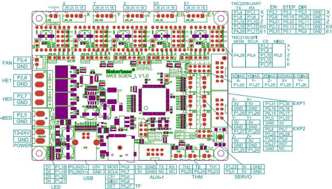
I have TMC2208 version the same, presented here on the pic.
https://github.com/KevinOConnor/klipper/issues/542
I have only one idea, if branch described here was not merged with delta branch.
People has here the same error and I did not understand if it was fixed and how.
Please navigate me to the key words, if you have idea. Thanks in advance.
vladT0
on 1 Dec 2019
The most common reason for the TMC2208 to not identify is the board not having motor power during startup. The other common failure is when the UART pin is not correctly routed to the micro-controller. Your pin assignment looks okay according to the given picture. However, some tmc2208 stepsticks may use a different pin for pdn-uart than the board is expecting, and/or the stepstick may require a solder jumper to be soldered.
You may wish to comment out all but one of the tmc2208 config sections and see if you can get any of the drivers to configure.
The work-rotary-20191119 branch has all recent changes. The tmc2208 code has no relation to the rotary delta kinematics so it seems unlikely they are related.
-Kevin
KevinOConnor
on 1 Dec 2019
FYI, I've updated the work-rotary-20191119 branch. The latest code changes the default stepper angles (stepper_a is now at 30 degrees, b at 150, and c at 270). I've also added some basic boundary checking to the code.
cd ~/klipper ; git fetch ; git checkout origin/work-rotary-20191119 ; sudo service klipper restart
-Kevin
KevinOConnor
on 2 Dec 2019
@KevinOConnor : you was right. UART Init issue was fixed, I added comment here https://github.com/KevinOConnor/klipper/issues/542
I tested new version. Stepper_a is now at 30 degrees, b at 150, and c at 270 : confirmed.
New issue. Real distance Z ( as example ) is far enough from G0 Z0; G0 Z100; I don't know the reason : tmc2208 in UART mode or anything else. Seems step_distance is correct. Do you have idea ?
I understand how 1/16 static step is working, but I am not sure I understand UART mode.
klippy.log
printer.txt
I tried M122 command, but I assume it is not implemented in Klipper.
vladT0
on 2 Dec 2019
New issue. Real distance Z ( as example ) is far enough from G0 Z0; G0 Z100; I don't know the reason
Sorry, I didn't understand that.
I tried M122 command, but I assume it is not implemented in Klipper.
You can use the DUMP_TMC command (see docs/G-Codes.md for details). Your config looks okay to me, though. You'll likely need to get the tmc2208 specifications from Trinamic in order to read the DUMP_TMC output.
-Kevin
KevinOConnor
on 3 Dec 2019
Sorry for the bad explanation.
1) G28; G0 Z0; and measure distance from the nozzle to the table.
2) G0 Z100; Expect nozzle distance is 100mm from the point 1, but it is a bit less.
With LV8729 and static 1/128 micro-steps result was very closer to 100mm.
Next steps. I am going to simulate printing. I mean print something without filament.
Will it work ?
vladT0
on 3 Dec 2019
Expect nozzle distance is 100mm from the point 1, but it is a bit less.
That sounds like a calibration issue. I don't know why it would be different with the lv8729.
If the upper_arm_length is not 170mm, if the lower_arm_length is not 320mm, or if the distance from the effector joint to the plane holding the shoulder joints is not 160.9mm (412.9 - 252) when the endstop triggers, then it will result in Z moves being skewed.
If you run GET_POSITION after each movement, what does it report and what are the real distances?
I am going to simulate printing. I mean print something without filament.
Will it work ?
As far as I know it should work.
-Kevin
KevinOConnor
on 3 Dec 2019
Hi Kevin !
GET_POSITION was very helpful for me.
1) G28
Send: GET_POSITION
Recv: // mcu: stepper_a:-9 stepper_b:-6 stepper_c:3
Recv: // stepper: stepper_a:0.687797 stepper_b:0.687797 stepper_c:0.687797
Recv: // kinematic: X:0.000000 Y:-0.000000 Z:252.000000
Recv: // toolhead: X:0.000000 Y:-0.000000 Z:252.000000 E:0.000000
Recv: // gcode: X:0.000000 Y:-0.000000 Z:252.000000 E:0.000000
Recv: // gcode base: X:0.000000 Y:0.000000 Z:0.000000 E:0.000000
Recv: // gcode homing: X:0.000000 Y:0.000000 Z:0.000000
Recv: ok
2) G0 Z0
Send: GET_POSITION
Recv: // mcu: stepper_a:-20014 stepper_b:-20011 stepper_c:-20002
Recv: // stepper: stepper_a:-0.859654 stepper_b:-0.859654 stepper_c:-0.859654
Recv: // kinematic: X:0.000000 Y:-0.000000 Z:-0.006265
Recv: // toolhead: X:0.000000 Y:-0.000000 Z:0.000000 E:0.000000
Recv: // gcode: X:0.000000 Y:-0.000000 Z:0.000000 E:0.000000
Recv: // gcode base: X:0.000000 Y:0.000000 Z:0.000000 E:0.000000
Recv: // gcode homing: X:0.000000 Y:0.000000 Z:0.000000
Recv: ok
Am I right, if in ideal case after G28 command line mcu: has equal figures for each stepper ?
Could you please explain, what does it mean here positive, negative and null position ?
I can imagine, if null position is when any of the endstops is triggered and you calculate position of other two how shift from it. But I am confused in this case with negative values.
vladT0
on 4 Dec 2019
I've added some information on GET_POSITION to the documentation: https://www.klipper3d.org/Code_Overview.html#coordinate-systems
Am I right, if in ideal case after G28 command line mcu: has equal figures for each stepper ?
No, it is normal for the "mcu" positions to differ. For example, if one stepper just happens to move a little further than another stepper during a G28 then the mcu positions would differ.
Could you please explain, what does it mean here positive, negative and null position ?
Hopefully the link above helps with that.
I can imagine, if null position is when any of the endstops is triggered and you calculate position of other two how shift from it. But I am confused in this case with negative values.
For the mcu position, negative just means the micro-controller has stepped more in a clockwise direction than a counterclockwise direction since it was last reset. It doesn't really mean much.
For the stepper position, it's the current angle (in radians) of the stepper (as tracked by the kinematics code). It's negative here, because if you looked at one of the shoulder joints the angle would indeed be negative.
The kinematic Z position is negative because the request to move to Z=0 could only be approximated due to the discrete nature of the stepper motors. The closest Klipper could get to Z=0 was actually 6 microns lower (at least as far as the kinematics code is tracking the position).
What were the actual measured positions during these attempts?
-Kevin
KevinOConnor
on 4 Dec 2019
1) G28
Real nozzle position Z = 230
Recv: // mcu: stepper_a:-10 stepper_b:4 stepper_c:6
Recv: // stepper: stepper_a:0.687797 stepper_b:0.687797 stepper_c:0.687797
Recv: // kinematic: X:0.000000 Y:-0.000000 Z:252.000000
Recv: // toolhead: X:0.000000 Y:-0.000000 Z:252.000000 E:0.000000
Recv: // gcode: X:0.000000 Y:-0.000000 Z:252.000000 E:0.000000
Recv: // gcode base: X:0.000000 Y:0.000000 Z:0.000000 E:0.000000
Recv: // gcode homing: X:0.000000 Y:0.000000 Z:0.000000
Recv: ok
2) G0 Z0
Real nozzle position Z = 0
Recv: // mcu: stepper_a:-20015 stepper_b:-20001 stepper_c:-19999
Recv: // stepper: stepper_a:-0.859654 stepper_b:-0.859654 stepper_c:-0.859654
Recv: // kinematic: X:0.000000 Y:-0.000000 Z:-0.006265
Recv: // toolhead: X:0.000000 Y:-0.000000 Z:0.000000 E:0.000000
Recv: // gcode: X:0.000000 Y:-0.000000 Z:0.000000 E:0.000000
Recv: // gcode base: X:0.000000 Y:0.000000 Z:0.000000 E:0.000000
Recv: // gcode homing: X:0.000000 Y:0.000000 Z:0.000000
Recv: ok
3) G0 Z100
Real nozzle position Z=102mm
Recv: // mcu: stepper_a:-13625 stepper_b:-13611 stepper_c:-13609
Recv: // stepper: stepper_a:-0.365367 stepper_b:-0.365367 stepper_c:-0.365367
Recv: // kinematic: X:0.000000 Y:-0.000000 Z:100.007842
Recv: // toolhead: X:0.000000 Y:-0.000000 Z:100.000000 E:0.000000
Recv: // gcode: X:0.000000 Y:-0.000000 Z:100.000000 E:0.000000
Recv: // gcode base: X:0.000000 Y:0.000000 Z:0.000000 E:0.000000
Recv: // gcode homing: X:0.000000 Y:0.000000 Z:0.000000
Recv: ok
Hi Kevin !
I have made measures for 3 positions in the prev. message. I am not sure, if nozzle physically is in the center of the heating bed. You know, how to calibrate delta. The step one, you have to calibrate endstops, when nozzle goes down exactly to the (0,0,0) position. I had impression, I can use mcu: info from GET_POSITION command for endstop calibration.
Regards,
Vlad.
vladT0
on 4 Dec 2019
Was this printer previously working on Smoothieware? If so, can you post the working Smoothie config?
If this is the first time getting the printer working then calibration will be needed. Unfortunately, I'm not familiar with the steps needed to calibrate a rotary printer. It would be nice to get the DELTA_CALIBRATE command working on rotary delta printers (as the calibration it does should be similar).
At a minimum, if the real distance from the tip of the nozzle to bed is 230mm after a G28, then position_endstop should be set to 230mm. (It may also then be necessary to then tune shoulder_height.)
Separately, I've updated the work-rotary-20191119 branch to improve the STEPPER_BUZZ handling. Can you check if everything works okay on it?
cd ~/klipper ; git fetch ; git checkout origin/work-rotary-20191119 ; sudo service klipper restart
-Kevin
KevinOConnor
on 5 Dec 2019
Was this printer previously working on Smoothieware? If so, can you post the working Smoothie > config?
Unfortunately not. I have started only tests with Smoothieware too, but for me in Smoothie was a lot of unclear things without any support from Smoothie team side.
At a minimum, if the real distance from the tip of the nozzle to bed is 230mm after a G28, then position_endstop should be set to 230mm. (It may also then be necessary to then tune shoulder_height.)
I see, this 252 came from Smothieware, where this distance had a little bit other sense, it is max travel for Z. I will create today photo of the printer and will show all measures, may be you can give
me advice where I am wrong. New version I will check too.
vladT0
on 5 Dec 2019
I've added initial support for the DELTA_CALIBRATE tool to the rotary delta kinematics.
To use this tool:
- Grab the latest code:
cd ~/klipper ; git fetch ; git checkout origin/work-rotary-20191119 ; sudo service klipper restart - Add a
[delta_calibrate]config section to the printer.cfg file. See the updated config/example-rotary-delta.cfg file for an example. - Set
horizontal_move_z=40in[delta_calibrate]andminimum_z_position=-40in[printer](or similarly large values). - Run
G28to home the printer. - Measure the distance from the tip of the nozzle to the bed. Then enter the following command (make sure to not move the head between measuring and entering this command):
DELTA_ANALYZE MANUAL_HEIGHT=<measured height> - Run
DELTA_CALIBRATE METHOD=manual. Do not issue a restart or otherwise change the config between this step and the previous step. Follow the directions at https://www.klipper3d.org/Delta_Calibrate.html to perform the basic delta calibration. - At the completion of the basic calibration run the
SAVE_CONFIGcommand. - Attach the resulting klipper.log file to this issue (success or failure).
Ideally the above will provide accurate values for your position_endstop and shoulder_height settings. After running the steps above, you should return the horizontal_move_z and minimum_z_position settings back to their defaults.
-Kevin
KevinOConnor
on 6 Dec 2019
Separately, I've updated the work-rotary-20191119 branch to improve the STEPPER_BUZZ handling. Can you check if everything works okay on it?
It is working correctly, but distance of the moving in the old version was around (+/-)1mm, in the new version it is much bigger.
vladT0
on 6 Dec 2019
I've added initial support for the DELTA_CALIBRATE tool to the rotary delta kinematics.
Seems new version has a bug in source code, G28 is not working anymore.
klippy.1.log
printer.txt
vladT0
on 6 Dec 2019
It doesn't like the shoulder_height = 390.8 that you recently changed. I'll have to look at why, but for now, I'd go back to 420 and see what delta_calibrate recommends.
-Kevin
KevinOConnor
on 7 Dec 2019
I have frame from 20x20 alu profile and actually moved down a little bit upper plate. So 390.8 is correct size now, but we can try again with 420.
Lets check, if I understand this parameter correctly.
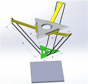
User Vector03 from the forum about Archie create those pictures. Do you think may be good idea
translate numbers from pics to the parameters for Klipper config file.
delta_e ххх.ххх 1
delta_f ххх.ххх 2
delta_re ххх.ххх 3
delta_rf ххх.ххх 4
delta_z_offset ххх.ххх 5
delta_ee_offset ххх.ххх 6
delta_tool_offset ххх.ххх 7
gamma_max_travel ххх.ххх 8
gamma_max ххх.ххх 8
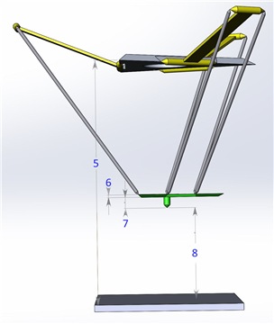
delta_z_offset # Distance from big pulley shaft to table/bed
delta_ee_offs # Ball joint plane to bottom of end effector surface
delta_tool_offset # Distance between end effector ball joint plane and tip of tool (PnP)
shoulder_height = delta_z_offset - delta_ee_offs - delta_tool_offset
vladT0
on 7 Dec 2019
Hi Kevin !
I finished calibration procedure according your document. Please see attached files. Optimized parameters are very close to measured. I understand how calibration is working now and I am going to repeat it again more precise. Thanks a lot for your help with rotary delta. I like Klipper !!!
Regards,
Vlad.
klippy.log
printer.txt
vladT0
on 7 Dec 2019
shoulder_height = delta_z_offset - delta_ee_offs - delta_tool_offset
Yes. From the diagram, position_endstop is <distance8> and shoulder_height is <distance5> - (<distance6> + <distance7>).
I finished calibration procedure according your document.
The log indicates that the DELTA_ANALYZE MANUAL_HEIGHT=<measured height> step did not work properly. I suspect you will need to perform that step to get a good calibration on a rotary delta printer. Try running the steps again at https://github.com/KevinOConnor/klipper/issues/1610#issuecomment-562364335 - that is, run G28, measure the distance from nozzle tip to bed, run DELTA_ANALYZE MANUAL_HEIGHT=<measured distance>, run DELTA_CALIBRATE METHOD=manual, run SAVE_CONFIG and then attach the log here.
If the printer is working and you are able to print basic objects, you could try running the "extended delta calibration" described at: https://www.klipper3d.org/Delta_Calibrate.html
-Kevin
KevinOConnor
on 8 Dec 2019
Hi Kevin !
I will repeat it again. The measured distance from the bed after G28 was the same and I had
wrong decision , I don't need in this case
DELTA_ANALYZE MANUAL_HEIGHT=
command.
Other issue.
G28 command is not working in all cases.
Example.
Send: M114
Recv: X:0.000 Y:70.000 Z:0.000 E:0.000
Recv: ok
Send: G28
Recv: !! Failed to home c: Timeout during endstop homing
Changing monitoring state from 'Operational' to 'Error:  Failed to home c: Timeout during endstop homing\x0a'
Recv: ok
It is very easy reproduce. If any coordinates is not very near to other two. One endstop triggered, second too, but last one need to travel. Instead of this we have this message.
vladT0
on 8 Dec 2019
The log indicates that the
DELTA_ANALYZE MANUAL_HEIGHT=<measured height>step did not work properly. I suspect you will need to perform that step to get a good calibration on a rotary delta printer. Try running the steps again at #1610 (comment) - that is, run G28, measure the distance from nozzle tip to bed, runDELTA_ANALYZE MANUAL_HEIGHT=<measured distance>, runDELTA_CALIBRATE METHOD=manual, runSAVE_CONFIGand then attach the log here.
I have done it exactly according document. Please see attached files.
klippy.log
printer.txt
vladT0
on 8 Dec 2019
I've updated the code on the work-rotary-20191119 branch. Hopefully, this should fully home all three arms during a G28.
cd ~/klipper ; git fetch ; git checkout origin/work-rotary-20191119 ; sudo service klipper restart
Otherwise, is the printer successfully printing?
-Kevin
KevinOConnor
on 10 Dec 2019
Otherwise, is the printer successfully printing?
Hi Kevin ! Not yet. I will finish extruder in the next one two days and will try.
I have 3 questions for a while.
1) Is it possible to have limit for the bed radius in the config file ? Or can I limit it only in slicer ? I noticed I can very easy set head out of bed with G1 command.
2) ENDSTOP_CALIBRATION : According doc:
Try moving the toolhead to several different locations and rerun G28 from each position.
Run at least five G28 commands.
Does it mean , I move head with G0 or G1 command or should it be 'by hand'? I did it with G-commands.
3) When you update source code, how I know, if I need to update host software only or microcode
part too and re-flush SD for the printer motherboard
Regards,
Vlad.
vladT0
on 11 Dec 2019
Is it possible to have limit for the bed radius in the config file ?
There is no user configurable limit right now. It's possible to add one. (The code does enforce a limit, but that is only to prevent internal math errors.)
Does it mean , I move head with G0 or G1 command or should it be 'by hand'?
Either is fine.
When you update source code, how I know, if I need to update host software only or microcode
part too and re-flush SD for the printer motherboard
See the FAQ: https://www.klipper3d.org/FAQ.html#how-do-i-upgrade-to-the-latest-software
Generally, the software will report an error if it is necessary to update the microcontroller code. The rotary delta kinematic support has not required any changes to the micro-controller code.
-Kevin
KevinOConnor
on 11 Dec 2019
I've updated the code on the work-rotary-20191119 branch. Hopefully, this should fully home all three arms during a G28.
Hi Kevin !
Klipper was reinstalled to the new Raspbery PI 4 2Gb and updated to the latest version.
I can park right now head from any position with G28 command, but I have very strange effect.
I don't even know how describe it without video.
https://youtu.be/T_Ig_H435F4
1) After the pause I execute G1 Z0 X0 Y0
2) G1 Z200 X0 Y0
3) and finally timeline 0:46-0:47 of the video I started again G28 and you hear very strange sound and you see a jerk, is a sharp, sudden movement. I have impression one or two motors started first.
G1 command executed absolutely flawless.
Do you have idea why is that ?
Regards,
Vladimir.
P.S. Attached log file, config file is the same as in prev. post.
klippy.log
vladT0
on 12 Dec 2019
It looks like the update for G28 is not working well. I've reverted that change:
cd ~/klipper ; git fetch ; git checkout origin/work-rotary-20191119 ; sudo service klipper restart
Unfortunately, if the head is near the bed and not center, you will likely get the "Timeout during endstop homing" error. I'll have to think about how to fix that. (Klipper currently implements homing by internally assuming the toolhead is at a position far away from the endstops and then issues a movement towards the endstops - unfortunately, on a rotary delta, if Klipper assumes the toolhead is at a position farthest from the endstops (arms fully extended) then the stepper movement needed to maintain a 50mm/s Z move is very high and can lead to lost steps and similar issues.)
-Kevin
KevinOConnor
on 13 Dec 2019
Hi Kevin !
Finally I managed successfully print first calibration cube. Cube, from the geometry point of view, is far enough from ideal, but that is clear, I have to improve mechanical parts, tighten the belt and so on. I don't know if you could close this task and I will open new one, if I met new issues, but Klipper is working for Rotary deltas :) Thank you very much again for the help !!! I attached config file,
it is SGEN_L board, T2208 V2 steppers and Titan Extruder. If you would like copy it to the examples.
printer.txt
Regards,
Vlad.
vladT0
on 14 Dec 2019
Great. I'll try to get this branch cleaned up and merged into the master branch.
If you can get the "enhanced delta calibration print object" printed, I'd be interested in seeing the results of that test on your printer. (That is, I'd like to see the resulting klipper log file after running all the DELTA_ANALYZE steps at: https://www.klipper3d.org/Delta_Calibrate.html )
-Kevin
KevinOConnor
on 16 Dec 2019
Hi Kevin !
I will print calibration object, but before I would like to execute again end-stops calibration.
Just couple of words about theory. Ideal case for the rotary deltas: nozzle position , after command G1 Z0, is exactly in geometrical center of the table, but physically center of the table usually shifted anyway in the printer frame.
1) What is the best way to get information about order of endstops triggered and what are the delays between. I mean in ideal case all 3 endstops have to triggered in the same time, if nozzle was in the center. According Klipper documentation ENDSTOPS calibration procedure. Am I correct ?
G28
ENDSTOP_PHASE_CALIBRATE
G1 Z100 X10 Y10
G28
ENDSTOP_PHASE_CALIBRATE
G1 Z44 X-10 Y-10
G28
ENDSTOP_PHASE_CALIBRATE
G1 Z200 X33 Y0
G28
ENDSTOP_PHASE_CALIBRATE
G1 Z66 X0 Y10
G28
ENDSTOP_PHASE_CALIBRATE
G1 Z75 X20 Y-10
G28
ENDSTOP_PHASE_CALIBRATE
ENDSTOP_PHASE_CALIBRATE STEPPER=stepper_a
ENDSTOP_PHASE_CALIBRATE STEPPER=stepper_b
ENDSTOP_PHASE_CALIBRATE STEPPER=stepper_c
SAVE_CONFIG
2) According RepRap G-Code document " M666: Set delta endstop adjustment " command is not supported by Klipper ?
vladT0
on 16 Dec 2019
Endstop phase calibration is different from endstop position calibration.
The ENDSTOP_PHASE_CALIBRATE command does not depend on order of homing or when the switch hits. Just home several times and check if you get the same phase reported by ENDSTOP_PHASE_CALIBRATE. If you do, then the tool can help provide a minor benefit to repeatability. Given your ~25:1 gearing ratio, there is a good chance that the switch is not accurate enough to use endstop phases. If it is not accurate enough, then don't configure endstop phases - it's not a requirement. Note, if the switch is not accurate enough and endstop phases is enabled anyway, it will result in worse accuracy.
The endstop position can be calculated using the DELTA_CALIBRATE command. This tool is not dependent on the order of homing or when the switch hits.
The issue with G28 reporting a timing error is due to the code not issuing enough step commands during homing. Until this can be fixed, if you get the error, just run G28 a second time. It will not adversely impact calibration or print quality. The ordering of when the switches hit during homing is not important.
I mean in ideal case all 3 endstops have to triggered in the same time, if nozzle was in the center.
That method of calibration is not very accurate, and none of the Klipper calibration tools work that way.
According RepRap G-Code document " M666: Set delta endstop adjustment " command is not supported by Klipper ?
The best way to configure the endstop position is to use the DELTA_CALIBRATE command. If you want to do it manually, you can modify the position_endstop setting in the printer.cfg file.
-Kevin
KevinOConnor
on 17 Dec 2019
To be clear, ultimately I think the best way to calibrate will be with the DELTA_CALIBRATE command. The tool may not be tuning the best parameters on a rotary delta in the current development code.
Is there a short guide somewhere online describing how to tune a rotary delta printer? If there is, I can try to tweak the DELTA_CALIBRATE command.
The DELTA_CALIBRATE command works by trying lots and lots of different parameters for your config settings (arm lengths, endstop positions, radius setting, angles, etc.) until it finds parameters that would make the printer match the measurements done during the probing part of DELTA_CALIBRATE. It provides excellent results on linear delta printers and I think it can also work well on rotary delta printers.
The tool does need to know which parameters to attempt to tune though. (It's not possible to tune all parameters at once with the limited information it gets from the measurements.) I'm not sure what those parameters to tune should be on a rotary delta printer.
-Kevin
KevinOConnor
on 17 Dec 2019
Hi Kevin !
I disassembled printer, measured all parts again and assembled. Still, without software calibration, command G28; G1 Z0; gives me 4-5mm above table. I think this error is too big for 230mm Z-travel.
I am not sure only with gearing ratio, may be this parameter was calculated not very precise. What do you think, which value is more critical here ? step_distance ?
Regards,
Vlad.
vladT0
on 21 Dec 2019
### Enhanced delta calibration
Hi Kevin !
Finally I managed to process Enhanced delta calibration:
DELTA_ANALYZE CENTER_DISTS=73.28,72.64,72.95,73.35,72.91,73.18
DELTA_ANALYZE OUTER_DISTS=73.11,72.95,72.96,73.15,73.05,72.91
DELTA_ANALYZE CENTER_PILLAR_WIDTHS=9.05,9,8.95
DELTA_ANALYZE OUTER_PILLAR_WIDTHS=9.1,9.12,9.07,9.05,9.13,9.05
DELTA_ANALYZE SCALE=1.0
DELTA_ANALYZE CALIBRATE=extended
I think geometric errors are not so huge, but extended calibration gave me dramatic changes for printer parameters. I even did not start any test print after. I executed G28; G1 Z0; and I see
how head is landed absolutely not in the center and out of 0 for Z axis position. So I reverted back parameters. Hope log file explain more for you.
klippy.log
printer.txt
Merry Christmas!
Frohe Weihnachten!
Z Kaliadami!
Vlad.
vladT0
on 22 Dec 2019
Interesting. I made some tweaks to the delta_calibrate command. Can you grab the latest code:
cd ~/klipper ; git fetch ; git checkout origin/work-rotary-20191119 ; sudo service klipper restart
And test with this config:
rotary-printer-test-20191223.cfg.txt
Merry Christmas!
-Kevin
KevinOConnor
on 24 Dec 2019
Hi Kevin !
What I did :
1) Took latest version
2) Replaced config on rotary-printer-test-20191223.cfg.txt
3) G28; G1 Z0
Head is below the table on 0.1-0.2mm. I can not move list of paper.
Shall I re-calibrate(normal calibration and extended ) printer with new config ?
Regards,
Vlad.
P.S. I did not wait your answer and made extended calibration based on figures from my prev. post.
and your config. See attached log and final config. Executed G28; G1 Z0; head is below the table on 0.4 mm.
klippy.log
printer.cfg.txt
vladT0
on 24 Dec 2019
It is not valid to re-enter the DELTA_ANALYZE extended calibration parameters once the config file has changed. Doing so will cause corruption. The only way to redo the extended calibration is to print the test object again, remeasure it, and then run the DELTA_ANALYZE commands. (The DELTA_ANALYZE commands must be run while using the same printer config that was used during the print of the test object).
You could try restoring to https://github.com/KevinOConnor/klipper/files/3996787/rotary-printer-test-20191223.cfg.txt and then run the basic delta calibration again. Also, is the nozzle still 252mm from the bed after homing?
-Kevin
KevinOConnor
on 24 Dec 2019
Hi Kevin !
I am going to restart this procedure from the beginning step by step with updated software and let you know about results.
vladT0
on 24 Dec 2019
Hi Kevin !
Step by step what I did:
1) DELTA_ANALYZE MANUAL_HEIGHT=252.1
DELTA_CALIBRATE METHOD=manual
TESTZ Z=......... and finally SAVE_CONFIG
Results presented in step1.printer.txt
2) I printed calibration STL file. Measured all params as followed:
DELTA_ANALYZE CENTER_DISTS=73.02,71.58,72.99,73.78,73.4,73.53
DELTA_ANALYZE OUTER_DISTS=72.74,72.8,72.74,73.56,73.4,72.76
DELTA_ANALYZE CENTER_PILLAR_WIDTHS=9.39,9.27,9.4
DELTA_ANALYZE OUTER_PILLAR_WIDTHS=9.47,9.1,9.37,9.34,9.21,9.28
DELTA_ANALYZE SCALE=1.0
DELTA_ANALYZE CALIBRATE=extended
SAVE_CONFIG
Config file after this step is step2.printer.txt. Executed G28 and G1 Z0 and found head pos
0.5mm before table.
3) Executed again step 1. Config presented in step3.printer.txt.
4) I printed calibration angle. Nozzle was on 0.05-0.07 mm closees to the table as expected. First layer was not very good. But size of the model for X and Y was the same 50.3 mm, what is 0.3mm more than real model size. Extended calibration helped to change X and Y size.
Current tolerance is 0.6%.
Question: what is the best way to change permanent Z-0ffset as 0.05
from current ? Just to change position_endstop for each axies or it is other way ? I understand SET_GCODE_OFFSET Z_ADJUST=.05 is not permanent and I cna not store it to the config.
step1.printer.txt
step2.printer.txt
step3.printer.txt
klippy.log
Regards,
Vlad.
vladT0
on 27 Dec 2019
Thanks.
I'm a bit confused by the step3.printer.txt file. It shows there were three DELTA_ANALYZE commands run: DELTA_ANALYZE MANUAL_HEIGHT=252.1, DELTA_ANALYZE MANUAL_HEIGHT=251.05, and DELTA_ANALYZE MANUAL_HEIGHT=251.9. The idea with setting the manual height is to use a tape measure (or similar) to measure the actual real distance from the bed to the tip of the nozzle after homing. That distance should not change with any calibration. (That distance is purely based on the physical characteristics of the printer and its endstops.)
The calibration is not expecting multiple manual height measurements, so you should remove them from the config. You don't have to recalibrate - just modify the printer.cfg to remove the lines starting with manual_height1 and manual_height2 from the bottom of the file. If the real distance from nozzle to bed after homing (as measured by a tape measure, or similar) is not 252.1 then also update the manual_height0 to the actual real distance, and then run RESTART followed by DELTA_CALIBRATE to redo the basic calibration (which will use the updated manual_height values along with the results of the last extended delta calibration).
Separately, the results of the log look very good. The key info from the log is the following:
height orig: 252.097905 new: 252.103240 goal: 252.100000
height orig: -0.100694 new: 0.002555 goal: 0.000000
height orig: 0.051089 new: -0.078808 goal: 0.000000
height orig: 0.023839 new: 0.007232 goal: 0.000000
height orig: -0.027486 new: -0.003746 goal: 0.000000
height orig: 0.059688 new: 0.074845 goal: 0.000000
height orig: 0.039474 new: 0.049885 goal: 0.000000
height orig: -0.043853 new: -0.055185 goal: 0.000000
distance orig: 65.000000 new: 63.873576 goal: 63.630000
distance orig: 65.000000 new: 63.503642 goal: 62.180000
distance orig: 65.000000 new: 63.750756 goal: 63.720000
distance orig: 65.000000 new: 63.993858 goal: 64.390000
distance orig: 65.000000 new: 63.234283 goal: 64.000000
distance orig: 65.000000 new: 63.894963 goal: 64.260000
distance orig: 65.000000 new: 63.855670 goal: 63.270000
distance orig: 65.000000 new: 63.974574 goal: 63.700000
distance orig: 65.000000 new: 63.331700 goal: 63.370000
distance orig: 65.000000 new: 63.797881 goal: 64.220000
distance orig: 65.000000 new: 63.893892 goal: 64.190000
distance orig: 65.000000 new: 63.375976 goal: 63.480000
The "orig" info shows where the printer thought it was located during the calibration print, the "goal" info shows where the printer was actually at during the calibration print (as provided by your measurements), and the "new" info shows what the new calibration should result in for future prints.
Your differences between "goal" and "new" are very small - which is great. It is true that the new location for position x=0,y=0,z=0 is 0.078808 lower than it should be. The calibration did this so that the other measurements have less error. If you add in a SET_GCODE_OFFSET, you'll improve x=0,y=0,z=0, but make the other XY locations worse. Your results are very good for a delta, so hopefully you'll get quality prints without having to further tweak them. EDIT: Actually, your calibration thought x=0,y=0,z=0 was 0.002555 from the bed. I'm not sure why you're seeing a .050-.070mm difference. If the error is consistent across the bed, then yes, use SET_GCODE_OFFSET as described below.
If you do wish to add a SET_GCODE_OFFSET, then the recommended way to do that is to add a START_PRINT g-code macro which sets the desired SET_GCODE_OFFSET and then have the slicer call the START_PRINT macro at the start of every print. See config/sample-macros.cfg for an example. See also: https://www.klipper3d.org/Slicers.html
-Kevin
KevinOConnor
on 29 Dec 2019
Hi Kevin !
Thanks a lot for the explanations. I executed DELTA_ANALYZE several times, because I want to change Z offset and seems did it wrong way after extended calibration.
Question: According config file I found calibration proc. made changes also for the angles.
I think it is stable and static variables for the delta printers. Shall I manually correct them ?
Finally I have tried "pressure advance", but it is not working for me. Shall I open separate issue, or would be suitable for you, if I will show results here ?
Regards,
Vlad.
vladT0
on 29 Dec 2019
According config file I found calibration proc. made changes also for the angles.
I think it is stable and static variables for the delta printers. Shall I manually correct them ?
The calibration code will find settings that make the printer motion conform to the measurements you took during calibration. It can correct for minor deviations in the actual angles, but it it can also adjust the angles to account for minor deviations in other areas of the printer. This is discussed a bit at https://www.klipper3d.org/Delta_Calibrate.html#additional-notes . Most people (at least on linear delta printers) report better results using the values calculated from DELTA_CALIBRATE/DELTA_ANALYZE even if the results don't immediately seem correct.
The pressure advance system is totally separate from the printer kinematics, so best to raise in a separate issue.
Cheers,
-Kevin
KevinOConnor
on 30 Dec 2019
Hi Kevin !
I see. What would you like me to do another tests for rotary deltas or we could say Klipper is ready for such kind of printers ?
Regards,
Vlad.
vladT0
on 31 Dec 2019
I still need to clean up the code and commit it to the master branch. I'll look to do that sometime next week.
If everything is working well on your side then that's great. There's nothing further on my side right now.
Thanks,
-Kevin
KevinOConnor
on 31 Dec 2019
FYI, I did merge support for rotary deltas to the master branch (primarily as of commit ac863a95).
-Kevin
KevinOConnor
on 11 Jan 2020
Related issues
 aegelsky
·
3Comments
aegelsky
·
3Comments
 Michael-Bell
·
5Comments
Michael-Bell
·
5Comments
 talfari
·
5Comments
KevinOConnor
·
5Comments
KevinOConnor
·
6Comments
talfari
·
5Comments
KevinOConnor
·
5Comments
KevinOConnor
·
6Comments
Most helpful comment
FYI, I did merge support for rotary deltas to the master branch (primarily as of commit ac863a95).
-Kevin