klipper uses standard trapezoid acceleration as far I know. I never seen a firmware with s-curve like acceleration and I think it would work better for printers
Some video from https://www.youtube.com/watch?v=qYJpl7SNoww
Since klipper has enough processing power and the code is well organized I think it should be easy to implement.
 dragonnn
All 652 comments
On Thu, Dec 14, 2017 at 10:22:54AM -0800, Mateusz wrote:
klipper uses standard trapezoid acceleration as far I know. I never seen a firmware with s-curve like acceleration and I think it would work better for printers
Some video from https://www.youtube.com/watch?v=qYJpl7SNowwSince klipper has enough processing power and the code is well organized I think it should be easy to implement.
This certainly would be interesting. I don't have any immediate plans
to implement it.
S-curves would only need host code changes (no need to change the
micro-controller code).
I think one challenge to implementing s-curves would be proper
handling of lots of small moves. The current trapezoid generator can
seamless accelerate over many small moves, seamlessly cruise over lots
of small moves, and seamlessly decelerate over lots of small moves.
In effect, if one big long move is broken up into many small moves,
there is no adverse impact. This is a nice feature as current g-code
slicers tend to emit lots of tiny moves when handling arcs. Having
similar flexibility while using s-curves might be challenging.
-Kevin
 KevinOConnor
on 15 Dec 2017
KevinOConnor
on 15 Dec 2017
Yeah I know it would only need host code changes. Probably you are right that handling many small moves like on a arc could be challenging. But I think it could be worth the trouble.
dragonnn
on 15 Dec 2017
https://github.com/synthetos/TinyG/wiki/Jerk-Controlled-Motion-Explained
I stumbled over tinyGs implementation yesterday ( Was searching for an alternative to Mach3 for my cnc ) and thought it might be helpful.
Tiny G even accepts Marlin formatted G-Code but has no pressure advance implemented and relies on doing the calculations on a Arduino Due which is not as elegant as doing them on a pi imo.
In a perfect world i would control Cnc, co2 Laser and 3D printers straight from klipper.
My soul is on sale, what do you need kevin ;)
Edit: interestingly enough, ultimaker cloned tinyg for their next commercial controller ( based on a "Tigershark" motion controller board https://github.com/adamjvr/Tigershark3D )
 lenne0815
on 27 Dec 2017
lenne0815
on 27 Dec 2017
That TinyG wiki page is an amazing find! Those graphs are glorious :)
The 6th-order motion planning seems to be implemented here. Pay attention to the code sections that are #ifndef __JERK_EXEC:
https://github.com/synthetos/TinyG/blob/master/firmware/tinyg/plan_exec.c#L243
They're using 5th-order Bezier velocity curves to get 6th-order position planning. The velocity planning takes in a starting velocity (Vi), a target velocity (Vt), and the number of steps over which you would like to change velocity (mr.segments). The code then plans a velocity for each one of those steps using a 5th-order Bezier curve.
When planning each velocity change, the math assumes that acceleration and jerk start at zero. This allows them to significantly simplify the math.
I think this means that velocity can be non-zero at the start of each line, but acceleration must be zero at the start of each line. So if a large line were to be broken into many small colinear lines, I think the motion planning would be able to seamlessly cruise over those lines, but not seamlessly accelerate over them. Acceleration would happen briefly within each small line, but the acceleration would start/stop frequently across the many small lines.
I think they mitigate the issue by ignoring moves that are small until the accumulated error is larger than a certain threshold. I'm not sure how effective that mitigation would be for the gcode generated by 3D printer slicers.
Note that this is just my interpretation of the code/math, I could be wrong =P
 ceryen
on 3 Jan 2018
ceryen
on 3 Jan 2018
Note that they are still using trapezoids to drive overall velocity changes, it's just that the velocity changes are smoothed using the 5th-order Bezier curves.
If the Bezier math could be updated so that the start of each velocity curve has non-zero initial acceleration and initial jerk, then you could chain the acceleration ramp of multiple trapezoids together. This might then allow smooth acceleration over many small lines segments.
Within the Bezier math, I believe that D corresponds to initial jerk, E corresponds to initial acceleration, and F corresponds to initial velocity. They set the D and E coefficients to zero under the assumption that each velocity curve starts with zero initial acceleration and initial jerk. You could instead set the D and E coefficients to non-zero initial acceleration and initial jerk values. The D, E, and F coefficients would then constrain the values of P_0, P_1, and P_2, they would no longer be set to the initial velocity. The constrained values of P_0, P_1, and P_2 would then have to be propagated into the A, B, and C coefficients, and the rest of the math would have to be updated.
ceryen
on 3 Jan 2018
Hmmm would be make a difference if we would use a true s-curce or a smoothed trapezoid? I think the second would be even better for printing times and speeds.
dragonnn
on 3 Jan 2018
A true S-curve would theoretically lead to the smoothest motion, translating to less vibration, less noise, and higher quality prints. Simply smoothing the trapezoid might be good enough though depending on the smoothing used.
ceryen
on 3 Jan 2018
I think the main advantage of using s curve smoothing over plain trapezoidal planning is that the inertia of the linear drive is taken into account, doesnt matter that much with belts and pulleys and a light extruder, makes a much bigger difference trying to rotate a 5kg leadscrew. Ill have g2core up and running soonish on my big gantry cnc, im exited to see what it brings to the table irl, especially how it behaves in conjunction with toolpath smoothing from fusion360, beforehand toolpath smoothing was done by mach3 with sometimes more than lacking results.
lenne0815
on 3 Jan 2018
all these kinds of planning with curves are approximations.
In general, we have a physical system with physical limitations. We calculate some movement for it. But it can only follow the calculated movement if those physical limitations are obeyed.
The perfect planning would simulate the complete physical model with something like differential equations and would optimize movement calculations within the known limits.
For a limited acceleration you get the fastest movement if you always accelerate with the maximum (so the result is constant acceleration, which is used by ).
Acceleration is limited by the mass to be moved and the torque of the steppers, and also limited by the construction of the printer (e.g. you want to reduce resonance). It's not easily determined, so the value will be a result of experimentation and experience or you keep it safe by staying below a limit.
Now the question is, what is the physical meaning of higher derivatives (jerk, etc.) and by which physical conditions they are limited.
Sure, you could limit those too, which is done by the 6th-order motion planning.
BUT, who said it's the main problem?
All this assumes that these are constant limits. But for example the maximum torque a motor can produce is everything else but a constant.
That's why I agree with @lenne0815 that this kind of motion planning is probably most effective for CNC machines, because they have big masses and their motion limits may mostly depend on these alone.
Stepping is a mathematical problem in itself. A pure theoretical step would mean you have infinite velocity for an infinitesimal short time (-> Dirac pulse) at the edge of the step and zero for the rest. In reality there are several physical effects that smooth the behavior, like inductance of the motor coils, mass etc. It needs some clever engineering to optimize the behavior, that's why it takes something like a tmc2130...
I am not sure if simply adding more derivatives will help a lot, when at the same time assuming constant limits is known to be wrong.
They claim to be the only that use 6 orders, but I think it has a reason why the industry still uses only three. Probably the higher derivations are hidden by other errors in the model.
At least the 3rd order seems to make sense.
Seeing improvements depends a lot on the competition. I am sure 6th order motion planning will be better than Marlin. Though, I also saw improvement when switching from Smoothieware to Marlin, which was caused by Marlin forcing me to use lower acceleration, which improved a lot in the print. But real comparision is done by pushing the limits.
However, Klipper was clearly ahead of both.
So, I am excited to see some comparison between Klipper and some 6th order motion planning on a real machine.
The general strategy for movement algorithms seems to be trial and error.
Usually they assume some physical relations, then implement an algorithm based on these assumptions and try that. Some of this may improve movement, but then it's still not clear, if the success is only based on a random correlation or if the physical behavior is really understood.
I am usually missing the measurements to prove those assumptions. I understand that nobody wants to do this because it is a lot of work.
Today everything is simulated, but from time to time you need to prove if the simulation provides correct results.
I see some potential in the measurement features of the tmc2130. It could be used to really measure what's going on while moving and to find hotspots where movements could be improved.
May be at some time we can manage to log these values together with coordinates.
If everything is fast enough, measurements could also be used to adjust movement parameters in real time. TMC seems to have hardware controllers that can use those measurements.
May be the distributed nature of Klipper is not ideal to handle this kind of scenario. But at least it allows to have a dedicated MCU for the main axes (usually XY), which could handle such a control loop.
 hg42
on 4 Jan 2018
hg42
on 4 Jan 2018
@hg42 Hmm, albeit creating a real physical model is obviously the best way to do it i personally think that "6th" order motion planning is close enough, dialing in mms3 on my machine by trial and error will yield a pretty spot on image of the forces at play, after finding these values you usually back of that for atleast 20% because youll need to compensate for cutting forces etc, so dialing it in after a model wouldnt yield to much advantage irl.
Interesting find that you found marlin to be better than smoothieware, can you maybe check at what point in time that was ? Right now smoothieware and klipper are based on the same base model for motion planning and i wouldnt know how to explain a bigger difference there, so i guess it wasnt implemented into smoothieware at that point.
The reason we dont see advanced motion planners anywere is simple i think, machine manufacturers keep them well under wraps, cncs are usually sold by "look at this surface finish in this material at these feeds" which includes the motion planner part but its nowhere discussed.
I think the best bet is to test it but as long as g2core doesnt support pressure advance theres not really a point, that would hold back printing speeds so much that motion planner differences wouldnt really come into play imo.
lenne0815
on 4 Jan 2018
@lenne0815 my point is that even 6th order calculation doesn't help if it doesn't take into account all important(!) dependencies.
Example: on a delta printer, you have the linear axes along the towers where the masses of the carriages have to be part of the calculation and you have to add the mass of the effector with hotend, eventually an extruder etc. via some geometric calculation. This is not trivial, but usually the acceleration is still given as a fixed value for the linear axes. In this case 6th order doesn't help.
Or what about microstep length being different depending on the position in the step cycle? The same goes for torque. I guess these kinds of errors always have a greater effect than orders 4-6.
The firmware changed from Smoothieware to a recent Marlin bugfix-2.0.x (some weeks ago, also on the same Smoothieboard) to Klipper on Pi3+Mega2560/RAMPS+some_Melzi.
Marlin ran smoother than Smoothieware on my Smoothieboard, but as I tried to say, this was some kind of imaginary improvement, because Marlin somehow forced me to lower the acceleration settings. I am sure if I would use the same settings for Smoothieware it would be similar. But I also found if using sane settings Marlin2 can work as smooth as Smoothieware on my corexy.
I mentioned Marlin to show that comparisons are dangerous. There are too many things to forget.
E.g. how do you compare the jerk setting in Marlin with the junction deviation in Smoothieware? This has a huge effect on acceleration settings (and in fact this was the reason I had to lower acceleration with Marlin). I found if I use jerk near zero in Marlin it is quite similar to Klipper, but still not as smooth. There seems to be some roughness.
At least my Smoothieware version doesn't compare to Klipper, because Smoothieware uses segmentation (though I read that it now supports segment free planning, which I also tried but it didn't work). And I think Klipper calculates more exact, at least the movement is noticeably smoother than with Smoothie (and Marlin2). I can use higher speeds and I could also use some a higher acceleration if I would want. But I prefer to use low currents on my motors. So acceleration is low but speed is high.
I also used all three firmwares with tmc2130 on XY (in standalone mode for now ~= tmc2100) where you can hear every non-smooth movement as some kind of hum. But I cannot compare because it's difficult to do from memory. The difference is not very big and even some wind can create much different impressions.
hg42
on 4 Jan 2018
Hm,i think your over complicating it, a single delta stepper nearly always pulls the same load ( depending on the angle of the 3 axis it can differ a tiny bit obviously but in the grand scheme of things its negligible ) with setting mms3 close to its mechanical properties youll be very close to what the motor can actually achieve under ideal circumstances and then again one would back of that a bit so the motors dont stall when the extruder hits overextruded parts or warping overhangs.
A perfect model would just bring the system even closer to its theoretical maximum performance but after backing of a bit for rl reasons i think you would end up with pretty much the same outcome.
The main reason for scurve being theoretically better than trapezoidal is that accel ramps are not switched instantaneous but rather blended, just as the outcome of a simulation. Blending factors obviously not as precise as from a real simulation but then again as i mentioned already imo, plays no role irl as we have other factors outside of the linear system limiting machine movement.
Jerk from marlin cannot be compared because god bless it doesnt exist in klipper, its just a simple value how big an instantaneous speed change can happen, to high equates to stalling motors as they can compensate only so much oscillating overshoot, any value above 0 results in forced artificial ringing.
At jerk 0 marlin is just dead slow as theres afaik none or only very little blending going on at directory changes. ( i never tested jerk 0 on marlin, luckily i could jump straight to klipper once i realized what jerk in marlin does )
lenne0815
on 4 Jan 2018
isn't that what I said? I doubt the 4th to 6th order are noticeable at all. But if they are, I guess other things have to be taken into account first.
3rd order may be useful, but I am not sure. I want to see it, before I accept it.
Given that a stepper always starts at a minimum speed (it's not analog!) the jerk setting from Marlin may not be too unreal if not set too high. With my low settings this worked good enough. But I have to admit, I used Marlin only for a few weeks.
reason for scurve being theoretically better than trapezoidal is that accel ramps are not switched instantaneous but rather blended
I think this sounds better than it is. If you want to accelerate your car as fast as possible, do you slowly press down your pedal?
hg42
on 4 Jan 2018
@hg42 Jerk is used at any cornering entry speed conceivable jerk 20 happens in marlin from f.e. 100mms to 80mms or from 50 up to 70, its used basically to cut of all the nifty motion planning necessary for smooth movements with one big slap.
A car is a bad analogy as its acceleration ramps are self limited by design and thereby "forced 3rd order" the motor is held back by its connection to the street, if you hold back a stepper from its commanded pulsing it just stalls, so ideally you need to estimate how much its held back and account for that.
lenne0815
on 4 Jan 2018
You are taking this topic way too far. Just look at this video https://www.youtube.com/watch?v=qYJpl7SNoww this shows really good how in practice any think like s-curve is a good idea for a 3dprinter. It would allowing to maintain higher printing speed and acceleration without increasing the problem called "ringing". A good example of this problem https://cdn.thingiverse.com/renders/bc/d5/47/4c/c0/_7280628_preview_featured.jpg
dragonnn
on 4 Jan 2018
Note that the s-curve beer is even faster then the trapezoid and it doesn't split out. In a 3d printer we are to moving parts with have high inertia - a direct drive extuder, heatbead in a prusa like printer. When such mass stops or accelerates the belt stretches due the not smooth acceleration and this causes ringing
dragonnn
on 4 Jan 2018
Play the beer video at speed 0.25 in youtube. There is no noticeable acceleration phase at all or at least not appropriate for such a beer.
The video created by Trinamic https://www.youtube.com/watch?v=PGYBqAphBHw looks more correct, but you cannot see it in comparison.
The beer may be good for promotion and looks funny, but it is not exactly our problem.
However, I accept your explanation about the belts. It's a system with masses, springs and friction. Instead the beer has no damping at all.
But anyways, I understand the effect. I already said 3rd order may be useful. But 4 or even 6?
The slower acceleration at start and end of the move has to be compensated by a higher speed in between.
This has disadvantages:
- to reach the same performance in total the moves must be longer
- the speed is limited by extrusion
But on the other side bowden systems could have additional benefits?
For bowden systems there are people that want to keep the speed constant, especially at direction changes, so acceleration near zero might be good for that.
To be clear, I am not speaking against experimenting.
Klipper is the perfect platform to try this.
Anyone can do...
hg42
on 4 Jan 2018
I think the beer is good to visualize the effects but as its running a single up / constant / down ramp it doesnt reflect that much on what we are doing with our printers, the differences between scurve and trapezoidal arent that big imo. Still, it would be great to see somebody a lot more intelligent than we are implementing it in a way that it can handle shoddy slicer gcode output. Maybe some day soon slicers will be more akin to cnc gcode generators aswell, right now even basic functions like min segment length are not existing and i havent seen an arc ( might be wrong on that ) at all.
lenne0815
on 4 Jan 2018
I had a quick look at the math here to and tried the follow it in plan_exec. See here.
What is missing is a proper understanding of the trapezoid generator and derive its math. But at least it is a start.
 mabl
on 7 Feb 2018
mabl
on 7 Feb 2018
I'm really interested in seeing s-curve motion profiling on Klipper. I was going to have a crack at it myself.
This might be a bit long, but I set myself a task recently of figuring out the trapezoidal and s-curve motion profile maths. I've done the trapezoidal motion, but I've hit a roadblock on the s-curve. It ends up being a bit more complex and I've not found a nice method of representing it. So if anyone has an idea then please met me know.
This might be a bit long, but I'll try and explain my current logic.
As the acceleration profile is a order equation, this gives a velocity profile of the
order and a position of the
this gives the following equations.
https://www.codecogs.com/eqnedit.php?latex=a&space;=&space;\left\{\begin{matrix}&space;b,&space;0\leq&space;t<&space;t_{1}&space;\\&space;0,&space;t_{1}\leq&space;t<&space;t_{2}&space;\\&space;-d,&space;t_{2}\leq&space;t\leq&space;t_{3}&space;\end{matrix}\right." target="_blank">https://latex.codecogs.com/gif.latex?a&space;=&space;\left\{\begin{matrix}&space;b,&space;0\leq&space;t<&space;t_{1}&space;\\&space;0,&space;t_{1}\leq&space;t<&space;t_{2}&space;\\&space;-d,&space;t_{2}\leq&space;t\leq&space;t_{3}&space;\end{matrix}\right." title="a = \left\{\begin{matrix} b, 0\leq t< t_{1} \\ 0, t_{1}\leq t< t_{2} \\ -d, t_{2}\leq t\leq t_{3} \end{matrix}\right." />
Integrating gives velocity
https://latex.codecogs.com/gif.latex?v&space;=&space;\left\{\begin{matrix}&space;bt&space;+&space;v_{0},&space;0&space;\leq&space;t&space;<&space;t_{1}&space;\\&space;v_{1},&space;t_{1}&space;\leq&space;t&space;<&space;t_{2}&space;\\&space;-dt+v_{2},&space;t_{2}&space;\leq&space;t&space;<&space;t_{3}&space;\end{matrix}\right." title="v = \left\{\begin{matrix} bt + v_{0}, 0 \leq t < t_{1} \\ v_{1}, t_{1} \leq t < t_{2} \\ -dt+v_{2}, t_{2} \leq t < t_{3} \end{matrix}\right." />
Integrating again gives position
https://latex.codecogs.com/gif.latex?x&space;=&space;\left\{\begin{matrix}&space;\frac{bt^{2}}{2}&space;+&space;v_{0}&space;+&space;x_{0},&space;0&space;\leq&space;t&space;<&space;t_{1}&space;\\&space;v_{1}t&space;+&space;x_{1},&space;t_{1}&space;\leq&space;t&space;<&space;t_{2}&space;\\&space;\frac{-dt^{2}}{2}&space;+&space;v_{2}t&space;+&space;x_{2},&space;t_{2}&space;\leq&space;t&space;<&space;t_{3}&space;\end{matrix}\right." title="x = \left\{\begin{matrix} \frac{bt^{2}}{2} + v_{0} + x_{0}, 0 \leq t < t_{1} \\ v_{1}t + x_{1}, t_{1} \leq t < t_{2} \\ \frac{-dt^{2}}{2} + v_{2}t + x_{2}, t_{2} \leq t < t_{3} \end{matrix}\right." />
if we have a cruising speed of and a cruising time of
we can figure out the
and
times by
and
substituting these into the equation for x and solving for
solving the roots for this equation with gives you a positive root for
If the value for exceeds your
then you rearrange this to solve for
The problem with s-curve equations is that each term is at least 1 order more complex, so you have to solve for a lot more variables. Basically the acceleration and deceleration phases are this complex and it just makes things that little bit more difficult. There are probably analytical methods to find the solution, but I'm trying to be a purist and find a numeric method.
Anyway. I thought this might be interesting for people.
 richClubb
on 27 Mar 2018
richClubb
on 27 Mar 2018
Ignore my last comment, turns out scaling a sigmoid isn't as easy as I thought. But Wikipedia to the rescue https://en.wikipedia.org/wiki/Smoothstep. Is exactly what is needed for this problem and provides a generalized solution to any desired order/degree.
Here's a better picture (at least it helped me understand better) of how the smoothstep order affects the various degrees. Vel 0 -> 100 over 0.5 seconds. The labeled values show the max.

Also the ipython notebook file where I created this image and some smoothstep helpers. https://gist.github.com/Islandman93/33f242a2f768452019739b05b50be414
 Islandman93
on 3 Apr 2018
Islandman93
on 3 Apr 2018
Nice...
Based on my limited physical knowledge and my experiences with 3D-printing, I would say the limiting factor is mainly the acceleration.
Reasoning:
The mass to be moved is constant, so force and acceleration are directly proportional (force = mass × acceleration).
For a stepper motor the torque is limited.
The torque is proportional to the force for a given lever arm (= constant).
The second diagram shows an increase of acceleration, e.g. the red curve has nearly twice the acceleration.
So, I think, to see realistic dependencies for a 3D-printer, the diagrams should be recreated with keeping the maximum acceleration constant.
hg42
on 3 Apr 2018
@Islandman93 In an earlier comment, you asked why Bezier curves. Here is something you might find interesting: smoothstep is equivalent to the same-order Bezier curve with the first half of the control points set to 0 and the second half of the control points set to 1. So smoothstep is a Bezier curve with the control points set to specific values =P
ceryen
on 3 Apr 2018
For anyone looking at this thread who isn't 100% familiar, I put together these graphs to demonstrate the differences.
Trapezoidal Acceleration - 0th Order Accel Calculation

Trapezoidal Velocity - 0th Order Accel Calculation

Trapezoidal Position - 0th Order Accel Calculation

The kicks occur at each of the acceleration transitions, I don't have any traces to hand from accelerometer data, but I've seen it before and it's quite noticable. If you're using a small microstepping then this can de-cog the "position" due to the inertia. This results in a 2nd order position equation
S-Curve Acceleration - 1st Order Accel Calculation

S-Curve Velocity - 1st Order Accel Calculation

S-Curve Position - 1st Order Accel Calculation

Obviously this smooths out the kicks between transitions, but the equations are much more complex than the trapezoidal. This results in a 3rd order position equation
S-Curve 2nd Order Accel - 2nd Order Accel Calculation

S-Curve 2nd Order Velocity - 2nd Order Accel Calculation

S-Curve 2nd Order Position - 2nd Order Accel Calculation

This is again more complex than the 1st Order Accel Calculation, but I can't really see any benefit over the 1st order and it results in a 4th order position equation.
Thinking more about it, I'm making some assumptions on these profiles. The distance travelled is the same, the maximum velocity is the same, the time for the profile is the same, and the time travelled at a constant velocity is the same. However any optimisation performed on these profiles will have to be specific to the profile type. For trapezoidal profiles, we have "max accel", "max velocity", and a "min constant travel time". You can calculate the time for the manoeuvre based on these constraints. For an S-curve profile, we don't have to worry so much about the "min const travel time" as we're smoothing out the transition between max accel and max decel, so this removes a constraint from the modelling. For the 1st and 2nd order S-Curve profiles I've increased the max accel to make sure that the movement completes in the same time frame and with the same max velocity.
I've got the mathematica workbooks for these three if anyone is interested. I'm working on some python code to do the same thing. I'm hoping to set up some tests to instrument the difference between the three so that it can be more precisely quantified.
richClubb
on 4 Apr 2018
FWIW, there are three key math formulas that I think would be necessary to implement an S-curve acceleration scheme:
1 - given a start velocity and a move distance, what is the maximum final velocity that can be obtained?
2 - given a start velocity, a cruising velocity, and a distance under acceleration, what is the time it takes to move that distance?
3 - given a start velocity, a cruising velocity, acceleration parameters, and a distance into a move, what is the time that the head should be at that distance?
For reference, the current Klipper code (with constant acceleration) uses:
1 - end_velocity = sqrt(start_velocity^2 + 2*accel*move_distance)
2 - accel_time = accel_move_distance / ((start_velocity + cruise_velocity) * 0.5)
3 - time = sqrt(2*distance/accel + (start_velocity/accel)^2) - start_velocity/accel
So, if anyone looking at the S-curve math could condense it to these formulas, then I think that would help quite a bit.
KevinOConnor
on 4 Apr 2018
in general it's an optimization problem.
The optimization target is the time used for a print.
The main limit (I think) is the acceleration (because torque is imited and mass is constant).
So, I think the shortest time can be reached with maximum acceleration.
On the other hand, vibrations are a problem.
Which means frequencies should avoid several fixed values.
Now, does this sound like 6 orders of derivation to you?
I think constant acceleration is the best strategy.
You only have to avoid certain resonances. And this is a non-linear problem. Not sure how to resolve this, but I guess 6th order doesn't help.
And take into account, that any change will shift frequencies.
So simple AB tests are not real tests.
For a real comparisions, the same model has to be printed in the same time. And there should be several models because each model has it's own resonance frequencies.
hg42
on 4 Apr 2018
You only have to avoid certain resonances.
With constant acceleration, the jerk is (theoretically) an impulse (or Dirac pulse, if you prefer) when the acceleration changes, so will excite resonances of any frequency.
 bmc0
on 4 Apr 2018
bmc0
on 4 Apr 2018
@bmc0 I don't think a Dirac pulse in the third derivation will excite all frequencies in the original function (distance/time).
Instead the distance/time function is a very smooth curve.
IMHO the whole vibration/jerk/whatever thing is not really caused by the acceleration function itself. It's caused by the sequence of moves that depends on the printed part and the slicer.
The sequential pattern of the moves excites lower frequencies.
I believe, the limiting of higher order derivations forces the moves to slow down (take longer time), because the limits force a non optimized acceleration function (acceleration is not at the maximum over the whole acceleration phase, because the peak acceleration must not exceed the torque of the stepper motor). If you simply use a lower constant acceleration instead, so that each move takes the same time as for the other case, then you will probably have a similar effect, may be better.
For example, the diagrams above show, that you have to slow down to not exceed the maximum acceleration (which is proportional to the torque of the motor). For the red curves this would be about half of the acceleration. The move would take much longer then (I guess the time would be more than doubled). If you would reduce the constant acceleration instead to achieve the same time for the move, you would probably have even less vibrations.
hg42
on 4 Apr 2018
There must be a reason why demonstrations like this one show the liquid sloshing around so much more with a trapezoidal velocity profile. In that video, the move completion time is very similar, yet there is clearly less vibration with the s-curve profile.
bmc0
on 4 Apr 2018
@richClubb somehow I missed you comment.
I wonder why the first (constant acceleration) has a maximum acceleration of 4 and the others have 6.
They should have the same maximum, because it's limited by the torque (I think).
Or are you going to say that with S-Curve Velocity the acceleration could be higher?
I don't think so...
@bmc0 the videos look a bit suspicious to me. But may be I am tricked by some optical illusion.
But anyways, we don't have some fluid in a glass.
When I look at my corexy printer, I have no noticeable vibrations with a single move.
I only get vibrations if I do several moves and they change directions. My gut feeling is that there are some low frequencies that escalate the vibrations. The frequencies are in the range of the moves, not in a range that could be caused by the acceleration curves.
That's why I think the acceleration curve isn't our biggest problem, if it is at all.
hg42
on 4 Apr 2018
@hg42 I had to change the max accel if I wanted to keep the same max speed. Those graphs are more of an example on the different profiles for people who haven't seen them before.
As the acceleration gradually increases and decreases it might be possible to work at higher max accel and decel values, similarly to get the same area under the velocity curve you either have to increase the accel and decel or increase the max velocity. I'm simplifying the problem, as there are other constraints. For example if the movement is small then you'll not be able to reach your velocity peak and therefore any s-curve acceleration will mean the motion will take longer than a trapezoidal profile with the same acceleration.
richClubb
on 4 Apr 2018
On Tue, Apr 03, 2018 at 01:00:12AM +0000, Harald wrote:
Based on my limited physical knowledge and my experiences with 3D-printing, I would say the limiting factor is mainly the acceleration.
Reasoning:
The mass to be moved is constant, so force and acceleration are directly proportional (force = mass × acceleration).
For a stepper motor the torque is limited.
The torque is proportional to the force for a given lever arm (= constant).
In my experience, common 3d printer stepper motors have a massive
amount of torque. Way more torque than is necessary to accelerate the
print head at any reasonable acceleration rate.
Instead, in my experience acceptable acceleration is primarily limited
by other factors - too high of an acceleration causes "ringing" in the
prints, excessive vibration of the printer, inability to change
extrusion flow rates fast enough, jerking of the print head causing
previously extruded filament to be disturbed, etc.
So, I think it may very well be possible that selectively reducing
acceleration may allow for a much higher overall acceleration with the
same (or better) print quality. This is what S-curves are about -
slightly slower acceleration at the start/end of acceleration in
return for a higher overall acceleration.
-Kevin
KevinOConnor
on 4 Apr 2018
@richClubb from my experiences the velocity can be very high, if you keep the acceleration below the physical limit. So I'm quite sure, the acceleration has to be limited, not the velocity.
From a theoretical point of view, the acceleration is directly bound to max torque of the motor.
It's because torque = arm_length*force and force = mass * acceleration and arm_length and mass are constant.
If you exceed max torque the motor will skip.
S-curve will certainly be better at the same acceleration. But then the time for the move will be 1.5x longer, right?
In those videos they certainly didn't limit acceleration, otherwise the move time would not be the same.
So it's another use case.
It's the purpose of the optimization task to find the best solution inside the limits. So you cannot ignore them.
hg42
on 4 Apr 2018
@KevinOConnor
I think it depends on your use case. Are you printing at the limits?
What is limiting the speed? E.g. with a lame extruder you cannot print very fast.
Also, dynamic forces can be very high.
When I optimize my printers, I usually increase acceleration until I see skips.
I think a stepper motor skips, if the maximum torque is exceeded. right?
So at least for me it's the limiting factor.
It may also be questioned if the simple holding torque is the limiting value. Especially with microstepping it's much more complicated.
Then you have to find a balance for the motor current and cooling considerations.
Depending on the filament paths I sometimes have to reduce acceleration or speed to stay out of resonances. That's why I want to adjust max_accel and max_velocity while printing.
For me it's a fact, that vibrations heavily depend on the filament paths.
And yes, you can find a configuration, where any part will work. But that's a lot slower.
My former experiences showed that the junction deviation may play a bigger role. The last commit according to this changed some things at least in my test environment.
I always thought, the junction deviation algorithm doesn't look like a model for the physical system we have. It might be a kind of workaround for no proper timing of the acceleration curves.
hg42
on 5 Apr 2018
On Wed, Apr 04, 2018 at 08:27:14PM +0000, Michael Barbour wrote:
There must be a reason why demonstrations like this one show the liquid sloshing around so much more with a trapezoidal velocity profile. In that video, the move completion time is very similar, yet there is clearly less vibration.
I suspect most of these videos are just marketing. :-)
FWIW, here's my interpretation of why S-curves may be helpful:
During acceleration, the stepper exerts a force to move the mass of
the print head. It applies this force to a belt. Since every force
has a counteracting force, the stepper is also placing a force on the
frame of the printer.
The printer frame and the belts are not perfectly rigid - over small
time scales they can act like a spring. So, during acceleration, some
of the force moves the print head, but some of the force is stored as
a potential energy in the frame and belt. When the steppers stop
accelerating, the force the steppers are apply is greatly reduced, and
the potential energy in the belt and frame is released. This sudden
release can result in a "jolt" in the print head.
In contrast, with S-curves, the force that the steppers exert on the
belt and frame is gradually released. Thus, the potential energy in
the belt and frame would also be gradually released. This might then
reduce "ringing" in the print and reduce vibrations in the printer.
(To be clear, though, I think it definitely would need testing to see
what the real world impact is.)
-Kevin
KevinOConnor
on 5 Apr 2018
@KevinOConnor
Well, now you added a very different point of view.
And I think, you are right.
So, for this part of the system limiting the change rate of the acceleration might indeed be a huge improvement.
hg42
on 5 Apr 2018
@hg42 you make a good point and I 100% agree. I'm working on the optimisation problem at the moment. I've got the following constraint set, and the general objective is to minimise [t].
Where [c] rate of change of accel, [a] is acceleration, and [d] is the rate of decrease of acceleration. What do you think?
I'm mostly interested in the math of the problem, and hoping for a better method of movement as a result :) I know a lot of commercial CNC machines use higher order movement control, but they obviously tend to deal with heavier end effectors. One reason people use the trapezoidal movement control is that it is significantly less complex to perform and is "good enough", and generally you're right it is.
richClubb
on 5 Apr 2018
@richClubb I think even if CNC machines move more mass, they also move more slowly. So from this point of view it may be a comparable use case.
The more important difference might be the force on the end effector which is nearly zero for 3D-printers and high for CNC machines. Errors in the movement may also affect tool wear. From this point of view it seems to be a very different use case especially when looking at the limits this adds to the optimization task.
Klipper is ideal for experimenting with such algorithms, so simply give it a try.
Btw. it would be very nice to have a module for that, which can be swapped with different modules for the same purpose, may be even at run time. Then you could easily compare the effects while printing. I am saying this, because I know it's very difficult to objectively compare this from memory.
hg42
on 5 Apr 2018
@richClubb
c and d look very similar. Is c the rate of increase then?
I think the usual way would be to apply an upper limit to each derivation.
If you want to separate up and down (this could indeed be usefull), then it would probably make sense to also separate positive acceleration from negative.
So it could be:
[v <= v_max, a_min <= a <= a_max, c_min <= c <= c_max]
with a_min, c_min being negative values. A negative value for v seems to make no sense.
hg42
on 5 Apr 2018
@KevinOConnor @richClubb it may be interesting how Kevin's last revolutionary statement would change the optimization task.
Eventually c_min, c_max could depend on the speed and acceleration that are reached?
At least the "spring" is loaded proportional to the acceleration (F=m*a). A limit on the acceleration change rate would imply, that the maximum may not be reached for shorter moves (just like it is now for the velocity). So the spring can have different loads when released.
This "spring" view is very interesting, because it could explain why I think a lower acceleration would help more than other means.
hg42
on 5 Apr 2018
@ceryen Yeah foot->mouth I had no idea that bezier curves were as general as they are. Course I didn't know much about polynomials 2 days ago either. This problem is a really great way to learn.
@richClubb This process can be done numerically also, since the curves are defined polynomials. Additionally, the problem is further simplified for longer moves that reach the max velocity since the s curve will reach the end velocity in the same amount of time (albeit with higher maximum acceleration).
For those that are working on the math I've updated my ipynb with my attempt at the answer to Kevin's question 1 (and actually all of them rely on the same function). We can get the time from distance of any degree s shaped velocity by integrating and solving for the roots (this took a while to figure out but was surprisingly easy to do with numpy). My brain is fried right now and I can't get the scaling correct (so that it works for velocities larger than 1 and distances greater than 0.5). So the plots in the last cell aren't right. Was trying to scale distance as a function of the maximum distance from linear acceleration (since that and s will have the same max) but it didn't work and I started throwing random operations around...
Checkout the last cell for the function I'm talking about. https://gist.github.com/Islandman93/33f242a2f768452019739b05b50be414#file-smoothstep-ipynb
Islandman93
on 5 Apr 2018
@KevinOConnor I've solved for question 1 and 3 but am unsure if I've understood question 2 correctly.
My understanding is this: Question 1 is a query to find the max velocity and time of a planned move to determine if the acceleration phase will be cut short. And the solution I've written must only be used this way since it does not use any S curve calculations, simply the relationship between a certain degree of smoothstep and the ratio between it's max acceleration compared to a linear acceleration.
Question 2 Is simply how long Question 1 will take which I've written assuming that max velocity is not reached.
Question 3 actually pertains to planning where the head should be at a given time. For this I use the numpy polynomial package to integrate and solve for roots. I haven't done any speed testing on this but it's going to be definitely slower than the linear acceleration calculation.
The code for both questions resides in the last two cells of the ipynb here: https://gist.github.com/Islandman93/33f242a2f768452019739b05b50be414#file-smoothstep-ipynb
Let me know what else I can do to help.
For any that remain unconvinced at the massive effect this could have on printing, here are two simple videos showing how jerk affects the things we try to print. A simple move of 10mm at F4000.
Water: https://photos.app.goo.gl/fvf610BPKwiBhfJm1. An unattached print: https://photos.app.goo.gl/fumvrspkT6lWuUva2
Islandman93
on 7 Apr 2018
Slightly off-topic, but has anyone considered implementing tool-path smoothing using Bézier curves, b-splines, or an algorithm like this one? Maybe it wouldn't make much of a difference in reality, but tool-path smoothing is required for the motion planning to be "correct" in the strictest sense.
bmc0
on 7 Apr 2018
Typically thats done in the "slicer" have a look here https://www.youtube.com/watch?v=5PKR5ansIPo theres a modifier "smoothing deviation" There are implementations directy in the machine control software aswell ( Mach3s toolpath deviation modifier f.e. ) but they are difficult to work with as you dont know how parts turn out without actually running them.
lenne0815
on 7 Apr 2018
Hmmm looks like Marlin goes a step forward https://github.com/MarlinFirmware/Marlin/pull/10337
dragonnn
on 7 Apr 2018
@dragonnn thanks for the pointing to that.
Their implementation seems to work well.
The developer reports great improvements, though he did not tell how he tested, e.g. if printing time increased.
Apparently my former skeptical view is proven wrong.
Or may be, the effect is based on the springy behavior mentioned by @KevinOConnor.
At least the whole printer construction can be seen as a spring.
hg42
on 7 Apr 2018
I think the big question is not if printing time increased but if printing time increased beyond normal printing with lower acceleration and jerk.
I think comparing printing time this will be like that:
high acl and jerk which lowers quality of you print > printing with some kind jerk free algorithm > printing with lower acl and jerk which gives you the same quality as the jerk free algorithm
dragonnn
on 7 Apr 2018
The whole charm of that sixth order bezier curve approach seems to be that you can just keep on using the trapezoidal speed profile formulas, but replace the actual speed profile with the bezier curve. There will be no change in printing times then.
Initially, I had thought that this will give you different duration times and distances travelled, but instead everything remains the same, since the curve is symmetric around the "linear line" connecting start and end velocities. (Integral v(t) for t from 0 to 1 gives (v_start+v_end)/2)
Introducing this into klipper should be streight forward in this case. I'll have a look soon.
mabl
on 7 Apr 2018
I still assume a maximum acceleration, that the steppers cannot exceed without skipping.
The maximum acceleration limit may be wrong, but it is my personal experience and seems to be logical.
Of course this has to be proved, yet.
@KevinOConnor said that the acceleration-based-skipping limit is very high and doesn't matter here (which I doubt).
Assuming an actual acceleration limit, a constant acceleration results in the shortest possible printing time.
So, any non-flat curve will increase printing time (see red curve above, just scale everything such that the red curve does not exceed the constant acceleration curve).
If the printing time for the red curve would result in let's say twice the printing time, so to be comparable you could greatly reduce the constant acceleration instead.
Then compare the vibrations.
hg42
on 7 Apr 2018
but anyways, there is no reason the algorithm shouldn't be implemented. It will prove itself.
And as I said, I totally accept the "spring" theory.
Currently, my only concern is to keep an eye on the real reason (I will probably do some tests).
If it really is the "spring" behavior, then some things might have to be considered additionally.
E.g. a spring is usually preloaded or it may have some lash and this might result in some offset in the formulas.
hg42
on 7 Apr 2018
On Sat, Apr 07, 2018 at 01:02:22AM +0000, Islandman93 wrote:
@KevinOConnor I've solved for question 1 and 3 but am unsure if I've understood question 2 correctly.
My understanding is this: Question 1 is a query to find the max velocity and time of a planned move to determine if the acceleration phase will be cut short. And the solution I've written must only be used this way since it does not use any S curve calculations, simply the relationship between a certain degree of smoothstep and the ratio between it's max acceleration compared to a linear acceleration.
Question 2 Is simply how long Question 1 will take which I've written assuming that max velocity is not reached.
Question 3 actually pertains to planning where the head should be at a given time. For this I use the numpy polynomial package to integrate and solve for roots. I haven't done any speed testing on this but it's going to be definitely slower than the linear acceleration calculation.
The code for both questions resides in the last two cells of the ipynb here: https://gist.github.com/Islandman93/33f242a2f768452019739b05b50be414#file-smoothstep-ipynb
Thanks. I don't fully understand the information at that link.
I gather that for formula 1 and 2 there is an equivalent constant
acceleration such that the existing formulas can be used. And, that's
fine.
It's not clear to me what formula 3 is. I was really hoping there'd
be a simple math formula that would allow time to be calculated from a
distance.
-Kevin
KevinOConnor
on 8 Apr 2018
On Sat, Apr 07, 2018 at 03:08:17AM -0700, Matthias Blaicher wrote:
The whole charm of that sixth order bezier curve approach seems to be that you can just keep on using the trapezoidal speed profile formulas, but replace the actual speed profile with the bezier curve. There will be no change in printing times then.
Initially, I had thought that this will give you different duration times and distances travelled, but instead everything remains the same, since the curve is symmetric around the "linear line" connecting start and end velocities. (Integral v(t) for t from 0 to 1 gives (v_start+v_end)/2)
I see. I missed that as well.
However, I think an implementation of this form has two big quirks:
1 - Some small moves are acceleration only and are immediately
followed by another move with acceleration. The above s-curve
approach would result in a velocity S followed immediately by another
velocity S. That's probably not ideal.
2 - When comparing a move that goes from zero velocity to 200mm/s to a
move that goes from zero to 100mm/s, the acceleration from 0 to 20mm/s
will be significantly different between the two moves. That doesn't
seem right to me - if we're limiting the rate of acceleration to
account for the physics of the machine, I think we'd want to limit the
change in acceleration independent from the final velocity.
That said, it does sound like it would be an interesting test. If
nothing else, it would provide strong evidence on how effective
S-curves are at improving quality on various real world printers.
Introducing this into klipper should be streight forward in this case. I'll have a look soon.
I'd guess such a change could be limited to
stepcompress.c:stepcompress_push_const(). (For cartesian and corexy
printers - it's more complex on a delta.)
-Kevin
KevinOConnor
on 8 Apr 2018
I thought a little bit about holding torque and skipped steps etc.
I think, skips always occur at the end (or start) of a move.
I also have been convinced by some sentences of the Marlin developer, that the problem is the abrupt change of force.
So, an increased acceleration in the middle of a move may indeed work.
However, I didn't see a prove for a realistic situation, yet. Videos like "beer" or "pendulum" don't help here because the axes are heavily over-sized for the task. It's different for 3D printers.
Does anyone have a link to a demo using S-Curve/Bezier that has a higher mass and/or a weaker stepper motor?
This could be such a test, but the printer is very rigid anyways, so we cannot see how well it works:
(2) 300mm/s s-curve motion test
https://www.youtube.com/watch?v=4Hx7hGy0JnA
hg42
on 8 Apr 2018
That test can be simple
https://cdn.thingiverse.com/renders/bc/d5/47/4c/c0/_7280628_preview_featured.jpg
tweak you printer that it print the cube like on the right. Then enable s-curve and print the same g-code again.
dragonnn
on 8 Apr 2018
@dragonnn did you address me?
I have no printer that I could run with Marlin on 32bit...or did you think of something else?
hg42
on 8 Apr 2018
@hg42 yeah i address you, just giving an example of a test. Unfortunately I don't have a printer with could run 32-bit Marlin too. But maybe in a few days I can find someone.
dragonnn
on 8 Apr 2018
no hurry :-)
my main point was, if acceleration can exceed usual limits for constant acceleration if using jerk-controlled motion
hg42
on 9 Apr 2018
I've just found a potentially easy solution to this which is pretty low on computational complexity.
If we begin with a normal 0th order acceleration system (trapezoidal velocity) and we provide an acceleration ratio, we can make a pseudo s-curve motion system. which relies only on a few formula which could conceivably be implemented on the micro.
Given a basic trapezoidal motion system as shown here,
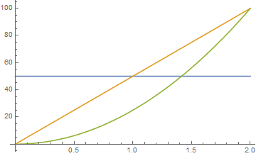
The blue line is the acceleration, the orange the velocity and green position.
If we use a acceleration ratio of 1.2, then the s-curve accel is 1.2 times larger than the trapezoidal. This gives a graph as follows.
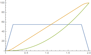
The blue line is the acceleration, the orange the velocity and green position.
So we get some of the benefit of ramping the accel rate, and the best thing is that it is completely conservative of both velocity and position.
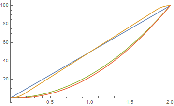
Blue is trapezoidal velocity, orange is pseudo s-curve velocity, green is trapezoidal position and red is pseudo s-curve position.
The joy is that this is a handful of formula. If 'a' is the trapezoidal acceleration which is hard-defined in the software.
and 'e' is our pseudo s-curve acceleration. the acceleration ramp rates are defined by.
So essentially if we define the 'accelRatio' we just need to ramp the accel up at a rate of 'd', until we hit 'e' and then down from 'e' to 0 when we get to the top of our travel, which is easy enough to calculate.
What do people think?
Also, just as an example, we get a nice graph if we put the accelRatio to 2, which is our 'perfect' s-curve.
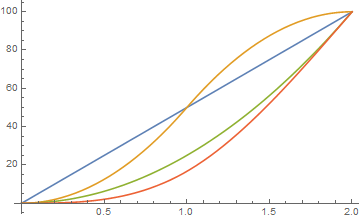
richClubb
on 10 Apr 2018
So it's constant jerk and higher orders are zero with peaks.
I think it's not a constant rate like for other firmware, but the steps define the points for calculating the new values? But this should still be simple, too.
I think the acceleration ratio should be adjustable. At least there is a "jerk" setting in other implementations (e.g. hardware chips). I guess, this is adjustable because the maximum possible acceleration may be limited, even if it may be higher with s-curves.
hg42
on 11 Apr 2018
Now there is no excuse to try it : https://github.com/MarlinFirmware/Marlin/pull/10373 ... ;)
 ejtagle
on 12 Apr 2018
ejtagle
on 12 Apr 2018
@KevinOConnor sorry I kinda threw up the code once I was done without much explanation. Let me try to explain better.
First, each degree of smoothstep has a different acceleration ratio compared to linear acceleration. With 6th order (EDIT: this is referring to smoothstep order 6 not 6th order position planning, see my @bmc0 induced epiphany below. 6th order position planning has an acceleration ratio of 1.875) having a ~2.7x max acceleration. Otherwise calculating the time to complete a move is the same (just use the linear functions with acceleration divided by the ratio). The fastest way to a proof of concept would be to just keep the current time estimates and understand that the max accel of s-curve will be higher.
Second, unfortunately there is no single formula to solve the distance/time calculation since the s-curve is higher than a quartic polynomial (unless using smoothstep order 1 which is cubic and numerically solvable). Therefore, the root of the polynomial has to be solved through an iterative process, called the Newton-Raphson method (this is also the same process used in the TinyG library). This method simply needs the derivatives (which we have) and a specified number of iterations to run for. Unfortunately, the Marlin S curve code is incomprehensible to me (serious props to writing Newton-Raphson in assembler). Also can anyone comment on why they use the phrase 6th-order when it's only a 2nd order smoothstep function? Am I missing something obvious and making this harder on myself?
I'm still working through this problem though I'm quite busy at the moment so progress is pretty slow, I'll focus on getting a pure python or C code implementation for the distance/time function as soon as I can. Though I still need to figure out how start velocity affects the curve and write a complete trapezoid with s-curve move generator.
As a side note, would you be up for adding a function in stepcompress.c that allows for python to send a vector of times and step direction and create a queue from these? I understand that the C code is faster, but for prototyping I think it's much easier just to have python calculate the step times (even though it will be slower). At least in this case it would allow me to use the NumPy solver instead of writing my own. Then once I know it works and have tested it I could create an optimized C version.
I've created a new example that can actually be applied to a stepper motor. IE: each step (or microstep) has a certain minimum distance, so the function needs to be queried at these distances. This example is in the last cell of the notebook. It should work for any distance/start velocity, though it does not take into account max velocity (this would just be an if statement).
New code is up at the same gist https://gist.github.com/Islandman93/33f242a2f768452019739b05b50be414
Islandman93
on 14 Apr 2018
Also can anyone comment on why they use the phrase 6th-order when it's only a 2nd order smoothstep function?
The function they use is S2(x) (aka "smootherstep"), which is a 5th-order polynomial. Using this curve for velocity gives 6th-order position planning.
bmc0
on 14 Apr 2018
@bmc0 thank you. I was confused with the 6th derivative and 6th-order planning. I originally thought that the goal was to reduce the large pulses in all derivatives up to pop. Which is why I had been using S_5(x) for my examples (12th order position planning lol). Upon further reading I've been able to find no practical examples of anything higher than jounce/snap and even then I still don't have an intuitive understanding of jounce or how it would affect printing.
Islandman93
on 14 Apr 2018
Therefore, the root of the polynomial has to be solved through an iterative process, called the Newton-Raphson method (this is also the same process used in the TinyG library). This method simply needs the derivatives (which we have) and a specified number of iterations to run for. Unfortunately, the Marlin S curve code is incomprehensible to me (serious props to writing Newton-Raphson in assembler).
if I understand this comment correctly:
I've got the newton-Raphson aproximation working. Only remaining to translate it to AVR assembler, and the PR for AVR will be ready...
this should be the C-code for Newton-Raphson:
https://github.com/MarlinFirmware/Marlin/pull/10337#issuecomment-379646120
The file stepper.cpp contains asm and C implementations and extensive comments about the Bezier curve starting at line 322:
#if ENABLED(BEZIER_JERK_CONTROL)
  /**
   *   We are using a quintic (fifth-degree) Bézier polynomial for the velocity curve.
   *  This gives us a "linear pop" velocity curve; with pop being the sixth derivative of position:
   *  velocity - 1st, acceleration - 2nd, jerk - 3rd, snap - 4th, crackle - 5th, pop - 6th
   *
   *  The Bézier curve takes the form:
   *
   *  V(t) = P_0 * B_0(t) + P_1 * B_1(t) + P_2 * B_2(t) + P_3 * B_3(t) + P_4 * B_4(t) + P_5 * B_5(t)
   *
...
Unless I'm misunderstanding something, the way Marlin implements this won't quite work for Klipper without a bit of additional modification to Klipper because it evaluates the Bézier curve at each step time to get the step rate, then calculates the step interval using the step rate. This is problematic because the step rate at t=0 is zero if the initial velocity is zero, so the interval is undefined (same goes for a final velocity of zero). In Marlin, this isn't actually a problem because the planner enforces a minimum step rate, so you never end up with an undefined interval. Klipper does not enforce an minimum step rate. Also, it seems to me (correct me if I'm wrong) that there could be quite a bit of error in the step interval calculation near the start and end since the interval is found using a (poor) linear approximation.
I think it would be much better to implement this using the method suggested by @Islandman93, since it allows more accurate calculation of each step time and doesn't break if the start and/or end velocity is zero. It certainly takes more CPU time, but I don't think that's a big problem (especially if it's implemented in C).
bmc0
on 14 Apr 2018
Hey! ... Please remember: One thing is theory, a very different one is reality!! ... Arbitrary precision calculation is pointless and a waste of resources, if at some point you are limited by the implementation. In your case, i assume there is a resolution limit in time (because, you must use a CPU timer to implement the delays between step pulses that are sent to a motor driver!!)
And ALSO, a given motor has finite steps per turn. So, you must take that into consideration.
As a control systems professor of mine told me a lot of years ago: Perfect theory means nothing (unless you are planning to never implement it) if you can't convert it into reality and can't use it to modify and control that reality. And if a model requires perfect and infinitely precise measurements to work, then you are wrong, and will never get it to work in practice.
Both arbitrary mathematical precision and perfect modeling when, due to mechanical wear/slash/friction , the system itself can´t be considered a time invariant system when you try to model it at such level of detail, means you are just plainly wasting your time.
Sorry to be rude, but is the plain truth, You should try your ideas at some point in reality, to make sure you are in the right path and you are not wasting your time pursuing an impossible result.
The marlin implementation is quite simple:
Fit a 5th order bezier curve to each CHANGE of speed (So, for each trapezoid there are 2 bezier curves, one for the starting acceleration phase, and another one for the ending deceleration phase. The trapezoidal cruising part is not handled by a bezier curve
The restrictions of that bezier curve are that both acceleration and jerk are 0 at the start and at the end of the curve, the value of the evaluated bezier must be the initial speed with t=0, and the final speed at t=1, ONLY at the start and end points. The remaining of the bezier curve can have acceleration and jerk and speed changes .
The bezier curve models SPEED versus TIME. We normalize time to the range 0 to 1, that makes computations easier.
With that information you should be able to follow what is going on in the code. The newton-raphson iterations are not used to compute the curve. Just to compute distance/time, because on AVR that quotient takes too much time otherwise.
Probably there are better approaches to this, but ensuring acceleration is 0 at the start and end of a movement, and that acceleration changes are smooth over time means applied forces do not change suddenly in magnitude or direction, and that means no vibrations and excitations of mechanical resonances of the machine.
That was the ONLY PURPOSE of that bezier interpolator, and it works amazinly well, compared to the previous trapezoidal implementation!
ejtagle
on 14 Apr 2018
Sorry, didn't mean to offend. What I was trying to say is that the way you've chosen to implement the algorithm doesn't seem to fit quite as well with Klipper as it does with Marlin (in my opinion). Clearly your implementation works well in Marlin; I just think that a different approach may be better for Klipper (in part because there are more CPU cycles to spare).
I'm currently working on an implementation that uses Newton-Raphson iteration to find the step times.
bmc0
on 14 Apr 2018
No offense taken. Do not worry. My main target was 32bit CPU archs on Marlin (i myself have a SAM3X8E based (Arduino Due) 3D printer. The fact that it also runs on AVR was more a challenge ... just to explore if it was possible at all. (and it was, but took a lot of effort!)
Nonetheless, unless you are planning to run on an Rasp PI, or something along those lines, the limitations still hold.
Unless you are running ServoMotors not based on stepper motors, there is a fact: You can´t control the exact position at all: Not only that: Torque varies with position. ALL micropositioning techniques suffer this problem.
So you must assume that the only reliable positions on a stepper motor are full steps: 3 steps per revolution. That means that the effective times when you can ACTUALLY control the motor position and force it to be in a given place, are when you are passing thru a full step.
So, entering the "super precise modeling game" will probably give you dimishing gains.
Most ARM based processors have either no floating point support, or just single precision! (24 bits mantissa) floating point support, so using integer arithmetic, if properly done, is way more precise and fast.
In my experience, if you want to do precise control of a motor, use servomotors, not steppers...
ejtagle
on 15 Apr 2018
On Sat, Apr 14, 2018 at 12:56:06PM -0700, Eduardo José Tagle wrote:
The marlin implementation is quite simple:
1) Fit a 5th order bezier curve to each CHANGE of speed (So, for each trapezoid there are 2 bezier curves, one for the starting acceleration phase, and another one for the ending deceleration phase. The trapezoidal cruising part is not handled by a bezier curve
The restrictions of that bezier curve are that acceleration is 0 at the start and at the end of the curve. Also, jerk is 0 at the start and at the end of the bezier, ONLY at the start and end points!. The remaining of the bezier curve can have acceleration and jerk .
The bezier curve models SPEED versus TIME. We normalize time to the range 0 to 1, that makes computations easier.
[...]
That was the ONLY PURPOSE of that bezier interpolator, and it works amazinly well, compared to the previous trapezoidal implementation!
Hi Eduardo,
Your Marlin implementation is impressive and quite interesting. I've
been looking through your code. In my own words (please correct me if
I'm wrong) the code:
uses a bezier curve to approximate smooth velocity transitions
at the start of an acceleration move it approximates A, B, C, F, and
inverse_step_count constantson each acceleration step it approximates the value of:
velocity(time * inverse_step_count) = Ax^5 + Bx^4 + C*x^3 + FMarlin then commands the stepper to move at approximately that
velocity. (Two approximations are done in this stage - the first is
a table lookup to calculate clock_ticks=CPU_FREQUENCY/velocity ; the
second approximation is scheduling steps using instantaneous
velocity instead of the definite integral of the velocity curve.)
It's good to hear the solution works well in Marlin, but unfortunately
I don't see a good way to implement the same in Klipper. The
difficulty isn't with the bezier curves - it's the last conversion
from velocity to step times that's problematic, as there is no
equivalent in Klipper. Fundamentally, Klipper is looking for a
formula that goes from distance to time (not a formula from time to
velocity).
Klipper is significantly different from Marlin. In Klipper, we use a
general purpose computer (such as a low cost Raspberry Pi) to
determine the precise time that each stepper should step, those step
times are compressed, sent to the micro-controller(s), and the
micro-controller then executes the provided schedule. To wit, Klipper
determines where the head should be at each moment and then commands
the steppers to take the appropriate steps at the appropriate times to
make that movement happen. There are several advantages to this
arrangement - the motions are more precise, we obtain significantly
higher step rates, we can implement the motion across steppers on
multiple micro-controllers, both the host and micro-controller code
are portable across a wide variety of architectures, the host code can
be written in a high-level language, etc. Unfortunately, the code
doesn't work particularly well with approximations - accuracy is both
a feature and a requirement.
Specifically, in the current code design, the high-level motion code
calculates how long each move takes, and the low-level step generation
code needs to generate the steps within that time frame (accurate to a
handful of clock ticks). We can change the high-level code and we can
change the low-level code, but the low-level code can't implement an
approximation that significantly deviates from the high-level code.
(Otherwise, we eventually try to schedule the first step for move M at
a time that is before the last step of move M-1 and that causes
havoc.) So, if the high-level code uses the formulas for constant
acceleration to determine that the head should accelerate 1mm in 100ms
then the X stepper generation code, the Y stepper generation code, the
extruder stepper code, etc. all need to generate all the step times in
a (nearly) exact time of 100ms. Alas, the Marlin velocity to step
time approximation isn't really compatible with that design.
That said, this is an interesting area, and I hope we can come up with
a solution that works well within Klipper.
Cheers,
-Kevin
KevinOConnor
on 15 Apr 2018
You are right. That is the exact approach Marlin uses.
But, the integral of the velocity over a given time is the distance. Yes, your calculations are more complex but not too much: Essentially, what you want is the inverse of the integral of the bezier curve. The integral itself is not a hard problem. The inverse has lots of roots, But, instead of going that way, i´d simply calculate the integral version, and then use newton-raphson iterations to find the inverse,
You probably know the maximum distance, because you know the mean acceleration and the time, so you can use NR to get the inverse of the function limited to that range of distance values. All other roots lie outside of that interval (of distance)
Going the analytical way is a problem when dealing with a 5th or more degree polynomial, iterative methods are the way to go)
ejtagle
on 15 Apr 2018
https://github.com/PymZoR/S-curve-Planner ... Could serve as a reference of a possible implementation...
ejtagle
on 15 Apr 2018
@ejtagle some remarks FYI
Klipper's time resolution is significantly higher, because it uses a tickless timer, so there is no interrupt on each tick. Interrupts are only generated where a step (or some other event) has to be scheduled. This is done by using a timer compare register. E.g. timer resolution can be 50MHz for LPC1768 without any problems (I think it is usually 16MHz for AVR). The LPC couldn't even process a 50MHz interrupt with trivial actions. But it works well tickless.
The Raspberry pre-calculates everything and the MCU only has to execute simple events at the times given by the Raspberry (or host, this can also be a PC).
It is incredible, that you made the AVR implementation work. This really seemed to be impossible...
hg42
on 15 Apr 2018
@bmc0 I pointed to Marlin because @Islandman93 said the NR implementation is incomprehensible for him because of the assembler code (or at least this was my understanding) and the linked comment contains the C code before it was converted. I didn't think, Klipper could directly use the algorithm from Marlin.
hg42
on 15 Apr 2018
@ejtagle you said:
The newton-raphson iterations are not used to compute the curve. Just to compute distance/time, because on AVR that quotient takes too much time otherwise
does this mean, it can also be calculated without NR if the processor is fast enough?
hg42
on 15 Apr 2018
Marlin is also tickless. In exactly the same way you describe. Interrupts are generated only when an step pulse is required.
Synthetos TinyG/G2 is the one that is NOT tickless, that is why i could not use their foward-difference evaluation of the bezier curve.
@hg42 Yes, NR is not needed on faster CPUs, In fact, the NR iterations are not even used in 32bit CPUs. NR is only used in AVR to speedup quotient calculation (and i checked the NR method is bit exact to the quotient result that is meant to calculate and substitute)
ejtagle
on 15 Apr 2018
Just to give you an idea on how Marlin works:
-For each movement, we know the distance
-For each unit of distance, we know the number of steps that must be sent to the motor
-For each movement we know the total time
-With that information, every time an step ISR happens:
1) we accumulate the elapsed time from the last interrupt to this one
2) With that time, and knowing the total time, we normalize the elapsed time from the start of the movement from 0 to 1.0
3) With that normalized time, we evaluate the bezier curve: That gives the instantaneous velocity
4) With that velocity, we can compute time to the next ISR
5) We program the timer to generate an interrupt at that time..
6) Repeat steps 1-6
ejtagle
on 15 Apr 2018
@ejtagle - for reference, an outline of how Klipper implements movement is at: https://github.com/KevinOConnor/klipper/blob/master/docs/Code_Overview.md#code-flow-of-a-move-command . If we can implement a bezier curve in the low-level step generation code (and leave the high-level motion planning code using constant acceleration) then the implementation could likely be done entirely in klippy/stepcompress.c:stepcompress_push_const() ).
The Kinematics document may also be of interest: https://github.com/KevinOConnor/klipper/blob/master/docs/Kinematics.md
KevinOConnor
on 15 Apr 2018
Basically, Marlin operation and Klipper operation is exactly the same. The only difference is that all the motion planning is offloaded to a host controller (rasperry pi or PC)
Going that route could allow to implement better planning/optimization techniques, and to perhaps create more precise pulses, because the ISR task is extremely simple. (Marlin does several calculations in the ISR)
ejtagle
on 15 Apr 2018
Basically, if running the algorithm i did for Marlin on a PC, by just using floats or even doubles, the calculations become a little less complex. You can easily evaluate the bezier in exactly the same way Marlin does,
ejtagle
on 15 Apr 2018
The bezier would give you speed, then you just numerically integrate the result, and probably a division, and you are ready to go
After all, increments are so small, that error tends to 0. And the supposed error only accumulates during the acceleration/deceleration phases, and is forced to 0 each time acceleration changes
ejtagle
on 15 Apr 2018
I've written some (completely unoptimized) code that implements the Bézier smoothing algorithm using Newton-Raphson iteration to find the step times, but I've noticed a problem: It interacts badly with the pressure advance algorithm. The extra steps are not distributed correctly, so the extrusion is inconsistent (too wide at the beginning and end of the acceleration/deceleration phase and too narrow in the middle).
Here's a patch if anyone wants to play with it (or tell me if I screwed something up): bezier_velocity_ramp.patch.txt. It's had very little testing, of course, so no guarantees that it won't break or damage something. You have been warned. Also, it currently won't work with delta printers.
bmc0
on 15 Apr 2018
@ejtagle thanks for the clear description. I guess my knowledge about Marlin is waaay too old...
Nice it's also tickless. This explains why it's working better than I expected.
hg42
on 15 Apr 2018
@hg42: I had also to study Marlin and specifically its planner and stepper functions. Right now is tickless, and it makes sense, because it saves a ton of useless interrupts.
Yes, under Marlin, i haven´t tested the pressure advance algorithm. As acceleration is not constant anymore, then force is not constant anymore, and that probably means pressure advance algorithm should have to be tuned to it.
Under Marlin, the acceleration ramping is applied to all axis and the extruder itself, but, the pressure advance algorithms i have seen are all linear approximations to the real problem, and probably not good enough.
The linear advance problem should be modeled as a delay or a low pass filter, so in fact, the best compensation probably would be to use a derivative of the distance multiplied by a correction factor to advance the extruder motor and compensate it (only theory, i haven´t tried it...)
ejtagle
on 15 Apr 2018
@bmc0 : Your implementation is probably correct. As i said before, linear advance should be proportional to the derivative of acceleration. All algorithms i have seen so far use a linear approximation that is not conceptually right, and they work because the trapezoidal model has constant acceleration at all points except the transition (junction) points.
If you estimate the advance of the extruder as the derivative of the acceleration (multiplied by a constant) i would not be surprised at all that the advance will work, even better than before ;)
ejtagle
on 15 Apr 2018
On extruder, we dont and can´t calculate a PID algorithm to control the amount of extruded plastic (that would need a way to measure extruded plastic), but the feed forward term of the controller CAN be implemented, as it does not require feedback! ... And if properly tuned, would ensure uniform extrusion of plastic even at high speeds :)
I think the linear motor model could be a close approximation to the extrusion problem. There is a term that depends on speed, and a term that depends on acceleration.
So, extrusion advance should depend on the derivative of speed, and the derivative of acceleration.
Basically, what i state is that Advance = Adv/dt + Bda/dt .
By tuning A and B, you get perfect extrusions even at high speed
ejtagle
on 15 Apr 2018
On Sat, Apr 14, 2018 at 07:25:12PM -0700, Michael Barbour wrote:
I've written some (completely unoptimized) code that implements the Bézier smoothing algorithm using Newton-Raphson iteration to find the step times
Nice!
FWIW, in my quick tests, the pow() function is noticeably slow, but
replace that with a few multiplications and your code is basically the
same speed as an unmodified Klipper. Also, my quick tests indicate
the Klipper compression algorithm works well with the change (both in
terms of bandwidth and number of generated queue_step commands). So,
very promising.
, but I've noticed a problem: It interacts badly with the pressure advance algorithm. The extra steps are not distributed correctly, so the extrusion is inconsistent (too wide at the beginning and end of the acceleration/deceleration phase and too narrow in the middle).
As @ejtagle indicates, Klipper models pressure advance as:
new_extrusion_velocity = nominal_extrusion_velocity + pressure_advance_coefficient * dV/dt
Since the dV/dt is constant with constant acceleration, the
extruder.py implements the above by modifying the start_velocity of
acceleration moves.
I was surprised that this interaction was noticeable, but in
retrospect, I guess it is to be expected. I suppose implementing the
full 'v = v + dv/dt' calculation would fix it.
-Kevin
KevinOConnor
on 16 Apr 2018
the pow() function is noticeably slow
Here's an updated patch with a couple optimizations: bezier_velocity_ramp.patch.txt. I replaced pow() with multiplications and modified bezier_step_time() to allow the previous step time to be used as the initial guess so it converges in fewer iterations.
I was surprised that this interaction was noticeable
To be fair, it's not particularly noticeable at "normal" print speeds. I noticed it because I printed a test cube at very high speeds. The print quality at that speed is garbage with pressure advance disabled, so it's pretty noticeable if something's not quite right.
I suppose implementing the full 'v = v + dv/dt' calculation would fix it.
How do you think this should be implemented? The obvious way to me is to write a special stepcompress_push() function for the extruder (or modify stepcompress_push_const()).
bmc0
on 16 Apr 2018
@bmc0 I did a tested yesterday with high print speeds and high acl/junction_deviation on a i3 like printer.
https://cdn.discordapp.com/attachments/295874406830440448/435048366360100874/P3150330.JPG
on left with s-curve on right on stock Klipper. But this was a one time shoot, so I can not guarantee those results.
Settings ware:
outline speed 140mm/s
overall printing speed 140mm/s too
max acl 3000
junction_deviation 0.1
dragonnn
on 16 Apr 2018
@bmc0 - FYI, one limitation of Newton's method is that it doesn't converge when the derivative at the solution is zero. This can cause failures if a step should be scheduled at the very start of a move (if that move starts at zero velocity) or at the very end of a move (if it ends at zero velocity) - for example:
$ echo -e 'G28\nG0 X0.23625\nM400\nG0 X1\n' > test.gcode
$ ~/klippy-env/bin/python klippy/klippy.py config/example.cfg -i test.gcode -o test-output -v -d out/klipper.dict
[...]
ERROR:root:bezier_step_time did not converge after 100 iterations!
@dragonnn: Cool, looks like it improved the ringing significantly!
@KevinOConnor: Thanks, I guess I'll have to add an additional couple of checks in the code.
bmc0
on 16 Apr 2018
@KevinOConnor:
It turns out that the problem in that particular case was using the previous step time as the initial guess. It does converge; it just takes more than 100 iterations (134 to be exact). If I set the initial guess to a fixed value or clamp it to [0.25, 0.75], it's not a problem.
Solving for the first step time on the second-to-last call to stepcompress_push_const() takes 28 iterations since step_offset is approximately -0.5 (but not less than or equal to -0.5), which is kind of a lot. It would make sense to have an easy-out when the distance being solved for is sufficiently close to zero or the end point, but at the moment I'm not sure how to determine what "sufficiently close" is.
bmc0
on 16 Apr 2018
@bmc0 - I'm not sure what the best solution is. (Not sure for pressure advance either.) I haven't had a chance to look in-depth. It seems config/example-corexy.cfg shows the problem more often than other configs (likely because the step size in that config is a nice even number).
KevinOConnor
on 16 Apr 2018
Yep, there's definitely some bad behavior with the corexy configuration. I guess I'll look into other root-finding algorithms. Bisection, for example, will always work and has no surprises near t=0 or t=1, but it's a bit slow compared to Newton's method. It would be possible to use a combination of methods to retain good average-case performance while avoiding bad worst-case performance.
bmc0
on 17 Apr 2018
But... on t=0, there is no need to evaluate anything. And on t=1, also there is no need. NR has the nice feature that is self correcting. So, just forcing the interval to 0-1.0 should work just fine.
You can take a look at the suggestions here:
https://math.stackexchange.com/questions/253432/improving-newtons-iteration-where-the-derivative-is-near-zero
ejtagle
on 17 Apr 2018
t is always in (0, 1), but due to (I assume) limited precision, it still does not always converge.
bmc0
on 17 Apr 2018
Would be interesting to print iteration values. So you'll see the pattern. I really doubt there is lack of precision. doubles have more than 53 bits of mantissa, more than enough to ensure convergence.
ejtagle
on 17 Apr 2018
@bmc0 - I played with the code briefly. Falling back to bisection when Newton's method comes up with an absurd guess seems to fix example-corexy.cfg for me. I put the code up on a work-bezier-20180415 branch.
KevinOConnor
on 18 Apr 2018
It is possible to somehow adjust the smoothing factor? Or it is fixed by the math. Would be nice to try different values.
dragonnn
on 18 Apr 2018
@KevinOConnor: My solution was making it bail if a convergence check fails and return the last guess. It seems to work well enough, but your solution is probably more robust.
On a related note, I've been playing around with the equations for pressure advance and I've realized that implementing pressure advance properly makes for a much more complicated problem. Without pressure advance, we're guaranteed that the axis never changes direction. This means that there is only one valid solution at each distance. With pressure advance, this no longer holds, so we'll need to be able to find all real roots within the interval and handle step direction changes.
bmc0
on 18 Apr 2018
@bmc0 You are right: To properly implement pressure advance means that there could be direction changes on the extruder motor. If there are direction changes on the extruder motor, then its maximum acceleration and torque should be taken into account, and that could impact the movement itself...
BUT... ;)
Again, there is a fact we can use: Due to the way Bézier interpolation works, IF the change in derivative values is smooth (no discontinuities at all) then there is also warranty that the Extruder motor movements will be smooth, just because the volume of plastic to extrude is linearly correlated to the traveled distance.
With pressure advance, you also link the speed, acceleration and torque of the extruder with the changes to the speed of the axis motors, so essentially, you end up controlling extruder in also a smooth way
Due to the mass that the extruder motor moves (10cm.. 40cm of plastic) compared to the mass of the hotend (500gr or more) and the reduction ratio of the gears employed at the extruder, the acceleration and jerk of the extruder motor should not be a problem at all.
If you want an analytical proof, get the maximum and minimum acceleration imposed to the extruder motor by the Bézier curve planner, and you will see what i say.
So, the problem can be simplied a lot without too much issues :)
ejtagle
on 19 Apr 2018
FYI, I was quite impressed with how well the automatic equation solving worked for Bezier curves. It occurred to me that if we can solve bezier_position(time) = position for position, then we should also be able solve the full kinematic(time) = position equation for position. That is, skip all the complex kinematic specific equations and instead use an iterative solver to schedule steps.
I got this up and running on delta. Basically, the only delta kinematic formula it needs is stepper_position(coord_x, coord_y, coord_z) = sqrt(arm^2 - (tower_x - coord_x)^2 - (tower_y - coord_y)^2) + coord_z. (Instead of using Newton's method, I'm using the "False Position" method, so no derivative is necessary.) In unit tests it generates steps that basically match the existing code.
Alas, the code is too slow right now (40x slower), but that's mainly because it is a pure python implementation. I'm hopeful that after I port it to C code it will be competitive.
@bmc0 - FYI, the algorithm that I'm using should be able to handle multiple stepper direction changes in a move. So, this could also be a way to improve pressure advance with S-curves.
KevinOConnor
on 25 Apr 2018
Newton-Raphson usually converges much faster. You don´t need the derivative of the function, as you can approximate the derivative by evaluating the equation at t+h, and at t, and then an approximation to that derivative is
(f(t+h) - f(t))/h
ejtagle
on 25 Apr 2018
On Tue, Apr 24, 2018 at 06:57:59PM -0700, Eduardo José Tagle wrote:
Newton-Raphson usually converges much faster. You don´t need the derivative of the function, as you can approximate the derivative by evaluating the equation at t+h, and at t, and then an approximation to that derivative is
(f(t+h) - f(t))/h
Right, Wikepedia refers to this as the "Secant method".
Alas, I wasn't seeing good behavior from Newton's method in this
particular use case. There were two problems I was seeing:
1 - when the velocity is near zero, Newton's method comes up with
crazy guesses. For example, consider a ramp from zero velocity to
40mm/s velocity over a 15ms time frame. If a guess is made at a low
time (eg, .001s), then the instantaneous velocity at that point is
quite low, and Newton can come up with a crazy time guess (eg, 200s).
Then it takes a large number of iterations to come back down from that
bad guess.
2 - even when the guesses are reasonable, since the velocity is
constantly increasing during acceleration, a guess based on the
instantaneous velocity is always a little short. So, Newton's method
is always chasing the correct answer. It then takes several
iterations to close within an acceptable error range of the correct
solution
Because of issue 1, it seems we need to bracket the guesses. (That
is, keep a range of past guesses and make sure no guess is made for a
time outside of that range.) This is what my work-bezier-20180415
branch does. However, once we bracket the guesses, we can use the
average velocity between the two brackets instead of an instantaneous
velocity to hopefully overcome issue 2. This is basically the "False
Position" method.
-Kevin
KevinOConnor
on 25 Apr 2018
Completely agree. NR has problems when the derivative of the function gives values near 0 (that is why at low speeds you have problems) and also, the initial guess is pretty important to ensure fast conversion : The better the initial guess, the faster the conversion.
I completely agree with you.
ejtagle
on 25 Apr 2018
What's the status of this work? Has any of it been added to master?
Thanks!
 w1ebr
on 4 May 2018
w1ebr
on 4 May 2018
On Thu, May 03, 2018 at 05:45:20PM -0700, w1ebr wrote:
What's the status of this work? Has any of it been added to master?
It has not been merged to master. You should be able to test on the
work-bezier-20180415 branch (or use the patches @bmc0 posted earlier
in this thread).
Separately, my testing with delta based entirely on an interative
solver has progressed a little. I've ported it to C code, and it's
only nominally slower than the existing code. (Specifically, the step
generation is about twice as slow, but since step generation takes
only about 5% of the cpu time, it's not a significant hit.) The code
is still way too rough to publish though.
-Kevin
KevinOConnor
on 4 May 2018
Hi guys,
I have been following a different way of solving the problem using a table look-up of delay values, that would enable any custom speed profile (I played with some of them). I have a rough demo too. My original idea was to use a sinusoidal s-curve (speed1 table in my code). But then I explore other weirder shapes too.
You can see my experiments in my blog's entries:
http://fightpc.blogspot.com.es/2018/04/how-to-get-sinusoidal-s-curve-for.html
http://fightpc.blogspot.com.es/2018/05/a-better-stepper-drive-s-curve.html
http://fightpc.blogspot.com.es/2018/05/stepper-motor-step-signal-timing.html
http://fightpc.blogspot.com.es/2018/05/more-experiments-with-motion-curves-for.html
http://fightpc.blogspot.com.es/2018/05/one-table-to-run-them-all.html
In essence, I replace the math by a lookup table and a method to strech the values to the proper acceleration time/number of acceleration steps. A linear interpolation should be in place to ensure more accurate results but it is still faster to calculate that than using a solver.
 misan
on 13 May 2018
misan
on 13 May 2018
@misan I think a table is nice. This could also allow to use measurements to calculate the table.
On the other hand I would like to see:
- tests with motors moving real masses (I think the bare stepper is much too far away from the use case)
- a comparison with s-curves
I generally think the (much simplified) physical model of moving masses leads to s-curves and therefore the movement should be optimal (max. acceleration time and min. jerk).
On the other hand the physics of a stepper motor are completely ignored and it's unclear if this error is small enough.
I think, for a bare motor the stepper physics would be dominant and a high moving mass would enforce it's own physics. That's why I don't think the bare motor is a good test.
hg42
on 15 May 2018
@hg42 Agreed. I am building a test rig with a carriage to do further tests.
misan
on 15 May 2018
@misan
I think, it would eventually be easier to add a rotating mass to the motor to simulate the effect of the mass.
However, a real carriage would be more realistic, because it also adds friction, which should be an important part in the formula.
I guess, friction could also be applied to a rotating mass, e.g. by adding a kind of brake pad or similar.
This would allow to compare different variants of mass and friction.
I think, the effect of friction adds something to the game.
The static friction ("stiction"?) is different from the dynamic friction (sliding or rolling friction).
I guess, starting acceleration from zero speed is significantly different from the non-zero case.
Not sure, what exactly happens when reversing the speed (back and forth) or at corners. What if the speed goes down to zero but doesn't stay there? do we have stiction in this case?
A table would allow to switch it for different cases. Though this could be done with different formulas, too, but a table always uses the same real time calculation and it's minimal.
hg42
on 15 May 2018
@hg42 You can see a comparison video of the four shapes I was testing now with a carriage (and a disconnected stepper as additional load) https://youtu.be/xit2FcFpqWM
misan
on 15 May 2018
I think y'all will understand the physics better if you remember that firmware / stepper pulses only control the TARGET position of the motor (coil current). Steppers produce torque proportional* to the ERROR between the target position and the actual rotor position. That's roughly-speaking a first-order low-pass filter between your carefully-calculated S-curves and the physical rotor motion. (This low-pass filter is the reason velocity jumps at corners work at all.) In effect, the S-curve step pulse profile is PAUSING acceleration momentarily at the starts of motion segments. You're probably seeing quality improvements in test prints because pausing acceleration momentarily means the forces/deflections from corner velocity jumps (Marlin "jerks" / junction deviations) are no longer directly additive with the forces/deflections from acceleration into / out of the corner. I suspect you could achieve much of the same benefit by simply applying the corner entry/exit speed to a brief coasting sub-segment on either side of the corner. Or using a 33%-67%-100% staged acceleration to approximate an S-curve. This would be a LOT easier for blending accelerations between consecutive gcode segments than finding an appropriate bezier curve...
note * The torque:error relationship is a sine function with period of 4 full steps, but sines are close to linear for small angles, so linear proportionality is reasonably accurate with typical 3d printing torques.
Another helpful thing to remember is that ACCELERATION is FORCE in a motion control system, so you can eliminate a couple confusing layers of derivatives in your "mental model" if you talk about FORCE and RATE OF CHANGE IN FORCE instead of acceleration and jerk. One important conclusion is that _the method of jerk control does not cause force spikes_! Lots of people describe this wrong (including Synthetos). Jerks -- real physics terminology jerks, not the incorrect "jerk" label used in 3d printer firmwares -- do not result in forces. They result in CHANGES in forces. What that means in practice depends on the type of load you're moving.
For a rigid body like a stepper rotor with no load attached, acceleration can and does change instantly (as fast as the coil current --> rotor angle error can change anyway), and infinite jerk is fine -- it doesn't violate physics, or produce any force spikes, or any positioning error in a trapezoid-velocity motion control system. Force can change pretty much instantly.
For a glass of beer on a horizontal linear stage, acceleration force is reflected by a _change in orientation of apparent gravity_, meaning the liquid has to move to a new "level" angle within the glass. Each acceleration value will have a different equilibrium fluid angle relative to horizontal. That change in fluid level requires a displacement of fluid mass to one side of the glass. Hey, guess what, that displacement of fluid mass to one side of the glass needs its own controlled velocity/accel profile, or it will experience an extreme force and slosh! Going from 0 to X linear stage acceleration requires the liquid to instantly shift to one side of the glass, which it can't do.
So what you've done by putting a liquid on the (horizontal) motion stage is physically take the second derivative of the linear stage motion, and apply that to the fluid position within the glass. Which means a 4th-order (or higher) S-curve linear stage motion results in a constant-acceleration profile (or higher) for the beer, and it's pretty happy with that as you can see from the video.
Are mill / printer motion stages more like rigid masses, or like liquids? Closer to rigid. But there's enough elasticity that you do have to worry about a little bit of oscillation from abrupt changes in force. It's not "sloshing" like the beer, but it IS an elastic system where force=k*deflection (to a good approximation). Changes of deflection of that elastic mass cannot occur instantly -- they have to be traversed in finite time -- therefore changes in force or acceleration cannot occur instantly, and infinite jerks don't actually exist. If you try to do an infinite jerk, that's effectively asking for an instantaneous change in deflection, and it acts just like a step input to a damped oscillator. It oscillates a bit and then settles out. This is a small contributor to ringing though. Velocity jumps are drastically larger.
 rcarlyle
on 16 May 2018
rcarlyle
on 16 May 2018
@rcarlyle thanks for a very good description of some physical relations.
I also tried to invalidate the beer demo for our case:
The beer may be good for promotion and looks funny, but it is not exactly our problem.
However, I accept your explanation about the belts. It's a system with masses, springs and friction. Instead the beer has no damping at all.
Thanks for making some things more clear.
I agree with most of your conclusions.
My gut feeling is that printers, that are not very rigid and therefore tend to "swing" (meaning all physical effects that behave like a pendulum) will benefit most from s-curves.
Printers stiffened by means like diagonal struts etc. probably will not see much improvement (like my own corexy, while it still has some springy behavior because of belts etc.).
As I also said before, most vibrations seem to result from longer series of movements. Vibrations are frequencies and those have additional rules.
Especially, if you get resonance at a frequency f, it will last for some time and following moves will add more power to it, if they also excite f.
This means, even if you mostly suppress excitement of frequencies by sophisticated acceleration curves, a resonance can escalate to a big vibration over a lot of movements (think of infill patterns).
You all know that marching in lockstep on a bridge is forbidden because of this?
hg42
on 16 May 2018
@misan thanks...
Unfortunately, I don't really see much of a difference, apart from the overall speed.
I can imagine a few methods to show differences:
- increasing acceleration until some shapes fail (skipping). Which is best?
- putting the axis on a frame (or simply a vertical bar), showing how movements excite vibrations. The vibrations could be made more visible by a mechanism like a dial gauge or a thin lever (using something like a wire?). A wire mounted vertically on the carriage could also be used, but it is hard to look at a moving object. Eventually a camera on the carriage could look at the wire or the camera could show it's own vibrations looking on a fixed point on the carriage (eventually mounted on some vertical bar).
hg42
on 16 May 2018
I decided to start working on this again a few days ago. Pressure advance now works correctly (see my bezier branch). The code supports 3rd- and 5th-order velocity ramps (3rd-order is the default). For now, I'm using the root finder in the GNU Scientific Library to find isolating intervals in cases where there might be multiple roots. The GSL root finder is, as one might expect, really slow compared to Newton-Raphson, but it's only used a maximum of one time per call to stepcompress_push_bezier() (only when advance_sd is negative). I initially tried using the GSL root finder to solve for all the step times, but it made klippy run about 7 times slower with the 3rd-order velocity curve and about 15 times slower with the 5th-order velocity curve. The performance hit with the current code is only ~3% using the example.cfg configuration with pressure_advance set to 0.055.
If you want to try it, you'll have to install GSL (should be called libgsl-dev in Debian-based distros). It does not work with delta machines at this time, so don't try it on a delta. I haven't tested it that thoroughly yet, so no guarantees that it won't break something or otherwise misbehave.
bmc0
on 4 Jun 2018
@bmc0 I gave your bezier branch ago, completed @oderwat PA test fine so gave a benchy ago seemed to be getting into some resonance, the print was looking ok then failed.
I have included the log
klippy.log
 BlackStump
on 5 Jun 2018
BlackStump
on 5 Jun 2018
Would be interesting if I could model a minimal test to reproduce this resonance problem. This is actually what I want to do with the gcwiz app. Replacing the longer print test with focused ones. Which is possible because gwiz can change all kind of parameters on the fly.
I was going to check out this branch myself. But I needed to get a stable printing result again after my hardware experiments :)
 oderwat
on 5 Jun 2018
oderwat
on 5 Jun 2018
On Sun, Jun 03, 2018 at 08:49:17PM -0700, Michael Barbour wrote:
I decided to start working on this again a few days ago. Pressure advance now works correctly (see my bezier branch). The code supports 3rd- and 5th-order velocity ramps (3rd-order is the default). For now, I'm using the root finder in the GNU Scientific Library to find isolating intervals in cases where there might be multiple roots. The GSL root finder is, as one might expect, really slow compared to Newton-Raphson, but it's only used a maximum of one time per call to
stepcompress_push_bezier()(only whenadvance_sdis negative). I initially tried using the GSL root finder to solve for all the step times, but it made klippy run about 7 times slower with the 3rd-order velocity curve and about 15 times slower with the 5th-order velocity curve. The performance hit with the current code is only ~3% using theexample.cfgconfiguration withpressure_advanceset to 0.055.
Interesting. Thanks.
I noticed you kept extrude_max_corner_v unchanged. I've not been able
to "wrap my head around" how to best handle extruder lookahead. We
need the lookahead, but the current code works on the principle of
constant acceleration. Though, perhaps using constant acceleration as
an approximation is sufficient.
I'll try to get my iterative solver code cleaned up and posted - if
for no other reason, you and others can then take a look at a slightly
different approach.
-Kevin
KevinOConnor
on 5 Jun 2018
@KevinOConnor: Yeah, I decided to leave the lookahead code alone for now... I'm not sure how to best implement it either. I'm definitely interested in seeing your solver code.
If you have time, would you mind looking at the log that @BlackStump posted? I have not been able to reproduce the error and I don't understand the step compression portion of the code well enough to figure out exactly what's happening. The error from stepcompress is on line 3923: stepcompress o=4 i=0 c=3 a=1: Point 3: 3 not in 2:2.
Also, I have to say that after running some more prints, I'm surprised how little difference there is with the Bézier smoothing (at least with my printer). Simple shapes like cubes are definitely a little better, but for most things it seems like it's mostly a wash. Pressure advance seems to work slightly better (may have something to do with the lack of instantaneous velocity changes). Maybe other printers would benefit more.
bmc0
on 5 Jun 2018
@bmc0 - FYI, I was able to reproduce the error by extracting the gcode from the log. Run ./scripts/logextract.py klippy.log, put the gcode below into a file named test.gcode.txt, and then run: ~/klippy-env/bin/python klippy/klippy.py klippy.log.config0002.cfg -i test.gcode.txt -o output -v -d out/klipper.dict
The common causes of a stepcompress error are: trying to schedule a step at a time less than the last scheduled step, or trying to move multiple steps instantaneously. I didn't investigate this particular case though.
-Kevin
KevinOConnor
on 6 Jun 2018
@KevinOConnor, @BlackStump: Thanks. I was able to find the problem: stepcompress_push_bezier() is called with steps=0.000029, start_sv=21.35, accel=9500, and advance_sd=-28.59. The move duration is 1.34e-6 seconds, so it's trying to schedule 29 steps in only 1.34µs... Not possible without multiple steps per clock cycle (at least on AVR). The issue does not occur with extruder lookahead disabled.
The root of the problem was that I forgot to add a check in extruder.py that was present in the original pressure advance code. Should be fixed now.
bmc0
on 6 Jun 2018
@bmc0 completed a 62 minute print with 5th-order enabled no problems
BlackStump
on 6 Jun 2018
@BlackStump: Good to hear! Have you noticed any improvement in print quality versus constant acceleration?
bmc0
on 7 Jun 2018
@bmc0 bit hard to compare as I need to print same print at same speed but subjectively I printed a benchy previously with constant acceleration albeit 80 minutes compared to a benchy with 5th-order @ 62 minutes and quality is very comparable.
early days but one might say I printed faster for the same quality. I intend to print more with the 5th-order as I dont see a down side as yet.
BlackStump
on 7 Jun 2018
btw I intentionally upped the speed when I printed with the bezier curve.
BlackStump
on 7 Jun 2018
FYI, I pushed the iterative solver code I've been working on to a new branch work-itersolve-20180609. This branch completely replaces most of the kinematic calculation code with an interative solver. I haven't tested this much and there is still a bunch of work to do (the extruder hasn't been converted, and S-curves have not been implemented). I'm uploading it in case anyone is curious.
The basic idea is that there is a function move_get_coord(move_time) that will return the cartesian coordinates where the head should be at any given time during a move. The kinematic code then provides a stepper_calc_position(coordinates) function that can convert a cartesian coordinate to the appropriate stepper position. These two function can then be combined to provide a move_time_to_stepper_position(move_time) function that provides the desired stepper position for any given time during a move. The iterative solver then finds the ideal step time by "solving" this combined function.
The performance looks pretty good (and the code hasn't been fully optimized). Initial results show about 10% more host processing on corexy and delta. Very minor additional cost on cartesian.
-Kevin
KevinOConnor
on 9 Jun 2018
@KevinOConnor @bmc0 so when I decided to give bmc0 bezier branch ago I created another sdcard for the orangepi zero+ so to swap back it was a simple matter swapping sdcards.
I have been printing and wondered is there really that much difference so flicked the bezier branch sdcard out and put in Kevin's constant accel sdcard started a print and on the infill I could really hear the steppers making noise.
I cancelled the print and put the bezier branch back in and started that same print, same gcode, the difference in sound is substantial especially on the infill ..The Creality Ender3 has metal stepper mounts mounted on aluminium extrusion so stepper noise is not dampened at all.
Is it worth pursuing, I think so
BlackStump
on 10 Jun 2018
On Sun, Jun 03, 2018 at 08:49:17PM -0700, Michael Barbour wrote:
I decided to start working on this again a few days ago. Pressure advance now works correctly (see my bezier branch). The code supports 3rd- and 5th-order velocity ramps (3rd-order is the default). For now, I'm using the root finder in the GNU Scientific Library to find isolating intervals in cases where there might be multiple roots. The GSL root finder is, as one might expect, really slow compared to Newton-Raphson, but it's only used a maximum of one time per call to
stepcompress_push_bezier()(only whenadvance_sdis negative). I initially tried using the GSL root finder to solve for all the step times, but it made klippy run about 7 times slower with the 3rd-order velocity curve and about 15 times slower with the 5th-order velocity curve. The performance hit with the current code is only ~3% using theexample.cfgconfiguration withpressure_advanceset to 0.055.
@bmc0 - I've been studying your code. Very nice! In particular, I
like how you've setup the coefficients so there isn't much code
difference between 4th and 6th order position functions.
BTW, where can I find the coefficients for 3rd and 5th order position
functions (ie, 2nd and 4th order velocity)?
I think the solver code on the work-itersolve-20180609 branch will
work with both bezier acceleration and extruder pressure advance. I
need to try and hook them up to see though.
-Kevin
KevinOConnor
on 13 Jun 2018
@KevinOConnor: Thanks!
I don't think 2nd order velocity would work very well unless you used a piecewise function. With a single quadratic you'd get an instantaneous change in acceleration at the beginning or end since there's no way to make the slope zero at both ends.
The 3rd and 5th order velocity curves are smoothstep functions (S1(x) and S2(x), respectively), which are always odd order. I guess you could find the coefficients for a 4th order s-curve, but I'm not sure I see the point. There seems to be very little (if any) difference between the 3rd and 5th order curves in terms of print quality.
bmc0
on 13 Jun 2018
@KevinOConnor: Also, since your solver doesn't require that the function be a polynomial, it may be interesting to try a sinusoidal s-curve like @misan suggested.
bmc0
on 13 Jun 2018
On Wed, Jun 13, 2018 at 01:05:22PM -0700, Michael Barbour wrote:
@KevinOConnor: Thanks!
I don't think 2nd order velocity would work very well unless you used a piecewise function. With a single quadratic you'd get an instantaneous change in acceleration at the beginning or end since there's no way to make the slope zero at both ends.
The 3rd and 5th order velocity curves are smoothstep functions (S1(x) and S2(x), respectively), which are always odd order. I guess you could find the coefficients for a 4th order s-curve, but I'm not sure I see the point. There seems to be very little (if any) difference between the 3rd and 5th order curves in terms of print quality.
Ah, okay. If only 3rd and 5th order velocity functions make sense
then that is fine.
On Wed, Jun 13, 2018 at 01:16:50PM -0700, Michael Barbour wrote:
@KevinOConnor: Also, since your solver doesn't require that the function be a polynomial, it may be interesting to try a sinusoidal s-curve like @misan suggested.
Yes - that would be interesting! I'm hoping that getting the
iterative solver code committed will result in more experimentation.
-Kevin
KevinOConnor
on 14 Jun 2018
FYI, I've updated the work-itersolve-20180609 branch with support for using the solver on the extruder, using it for pressure advance, and for implementing s-curve acceleration. It should work on all kinematics.
cd ~/klipper ; git fetch ; git checkout origin/work-itersolve-20180609 ; sudo service klipper restart
There's a new "acceleration_order" parameter in the config file (see the updated config/example.cfg file for the details). It should also be possible to change the s-curve acceleration type via a SET_VELOCITY_LIMIT ACCEL_ORDER=x command.
I've only done very light testing on this. I wanted to publish what I had - I'll be doing a series of prints over the next few days to see how it works on my printers.
-Kevin
KevinOConnor
on 14 Jun 2018
Make sure y'all test big cylinders, finely-faceted organic curves, and delta kinematics with this. I think you're at risk of getting some really undesirable behavior if acceleration goes to zero at every corner when a run of consecutive short segments are nearly in the same direction.
rcarlyle
on 14 Jun 2018
@rcarlyle IIRC, entry and exit speeds for each move should be set by the planner and would not be affected by the shape of the acceleration. Joined segments as in the circle case should keep the same entry/exit speeds as before. Right, @KevinOConnor ?
misan
on 14 Jun 2018
@misan yes the cornering SPEEDS should be the same with this approach (as far as I know anyway) but the entry / mid / exit accelerations will change a lot for gentle curves. Remember, continuous acceleration can span multiple short segments right now if the corner velocity jump is gentle enough to not trigger a corner slowdown. With constant-accel motion, if you have two small segments with nearly the same direction vector, you can continue accelerating through the corner. The Bezier curve approach has to stop accelerating at every corner, from what I understand. That’s bad behavior when you have a lot of small segments in a gentle curve — you’ll build less speed and you’ll get force pulsing (shaking?) as the drivetrain repeatedly accelerates and pauses acceleration.
You’ll never see this behavior with boxy prints on Cartesian machines, but it could cause undesirable results in other cases.
rcarlyle
on 14 Jun 2018
@rcarlyle ah, ok. Now I see what you mean. In the figure below the red line is the constant acceleration case, and the black line is the s-curve acceleration when the acceleration spans two segments. Right?
What I do not know is how prevalent that scenario might be IRL. (short moves, low acceleration and high feedrate).
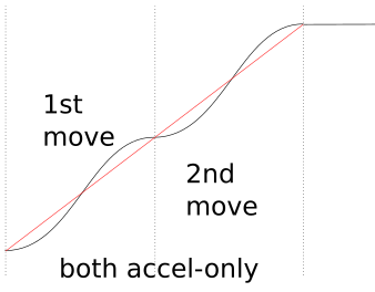
misan
on 14 Jun 2018
@misan yeah, that's it, thanks for illustrating it. How does Klipper handle delta motion? Is it segmented? I can't find the code for that. Segmented delta motion and finely-faceted arcs at the start/end of curves (ie arc before or after a sharp corner or travel move) will trigger this case. The criteria for it to occur is that you have small changes in direction vector between segments, when your segment length is meaningfully less than the distance it takes your printer to accelerate up to nominal speed. For some example numbers, say you're printing a large cylinder, say 200 mm diameter = 628 mm circumference:
- Arc facet size 1 mm
- Segment corner angle = 1 mm / 628 mm * 360 degrees = 0.573 degrees (I'm not going to do the math, but I am pretty sure this is too small of an angle for the planner to trigger any entry/exit speed slowdowns)
- Acceleration 1000 mm/s^2
- Slicer speed target 200 mm/s
- Constant acceleration time from 0 to 200 mm/s = (200 mm/s) / (1000 mm/s^2) = 0.2 s
- Constant acceleration distance = 1/2 * (200 mm/s) * (0.2 s) = 20 mm
- 20 mm of acceleration = 20 segments = 19 corners
So, acceleration will oscillate between the peak mid-segment acceleration and zero magnitude, 19 times. And then do it again at the end of the cylinder when decelerating. Yeah, I know most people don't do 200 mm/s cylinder perimeters with 1000 mm/s^2 acceleration, but that's just an extreme case to show the math. Lots of users will encounter it occasionally.
Will it actually cause problems? I don't know. Maybe not. Might end up being negligible compared to velocity jumps at sharp corners. I just think it's something you need to test. Or figure out a way to do non-zero acceleration through corners so this doesn't happen.
If you do stop at all corners (like milling firmwares often do) then this edge case disappears. But that's super slow, and really not a good approach for 3d printing because of flow blobbing issues. Milling softwares also often merge small segments into larger approximated segments or round off corners according to an allowable tolerance criteria, to keep speeds up. Stopping or rounding off sharp corners and dropping fine detail makes sense when you're running a 1/2" end-mill (since you can't make much geometry smaller than a 1/4" radius anyway) and don't have to perfectly synchronize extruder flow to tool position. But that approach can be an issue if you're doing fine detail printing work like surface embossing textures (eg the lettering on the back end of a Benchy), printing small mechanics, etc.
rcarlyle
on 14 Jun 2018
On Thu, Jun 14, 2018 at 06:15:53AM -0700, Ryan Carlyle wrote:
@misan yes the cornering SPEEDS should be the same with this approach (as far as I know anyway) but the entry / mid / exit accelerations will change a lot for gentle curves. Remember, continuous acceleration can span multiple short segments right now if the corner velocity jump is gentle enough to not trigger a corner slowdown. With constant-accel motion, if you have two small segments with nearly the same direction vector, you can continue accelerating through the corner. The Bezier curve approach has to stop accelerating at every corner, from what I understand. That’s bad behavior when you have a lot of small segments in a gentle curve — you’ll build less speed and you’ll get force pulsing (shaking?) as the drivetrain repeatedly accelerates and decelerates.
Yes - it is an open question how well this type of s-curve
implementation will handles lots of small moves.
On Thu, Jun 14, 2018 at 07:29:52AM -0700, Ryan Carlyle wrote:
@misan yeah, that's it, thanks for illustrating it. How does Klipper handle delta motion? Is it segmented?
No, Klipper does not segment moves on delta. Klipper finds the
precise step time for each stepper based on the kinematics of the
machine. This is why I think the iterative solver is interesting -
implementing the math to determine the precise step time on a delta is
complex and challenging. The iterative solver makes it dramatically
simpler - we just define a delta_stepper_calc_position() function (see
klippy/chelper/kin_delta.c on the new branch) which translates a
cartesian coordinate to the desired stepper position for that
coordinate. The iterative solver then "solves" that function to find
precise step times for a given move. (Specifically, the code devises
a function that calculates stepper_position from a move_time with:
stepper_position = delta_stepper_calc_position(move_get_coord(move_get_distance(move_time)))
and then determines next_step_time from next_step_position by
repeatedly "guessing" increasingly more accurate move_times until the
desired next_step_position is found.)
-Kevin
KevinOConnor
on 15 Jun 2018
Hi! I've tested Kevin's itersolve branch on my Railcore. These prints were at 75mms, junction of 0.02, Accel of 3000. The one on the left is bezier acceleration, 4th level, the one on the right is constant acceleration. The camera isn't good enough to show in photos, but the corners are a little worse with bezier acceleration, and the ringing is very slightly worse.
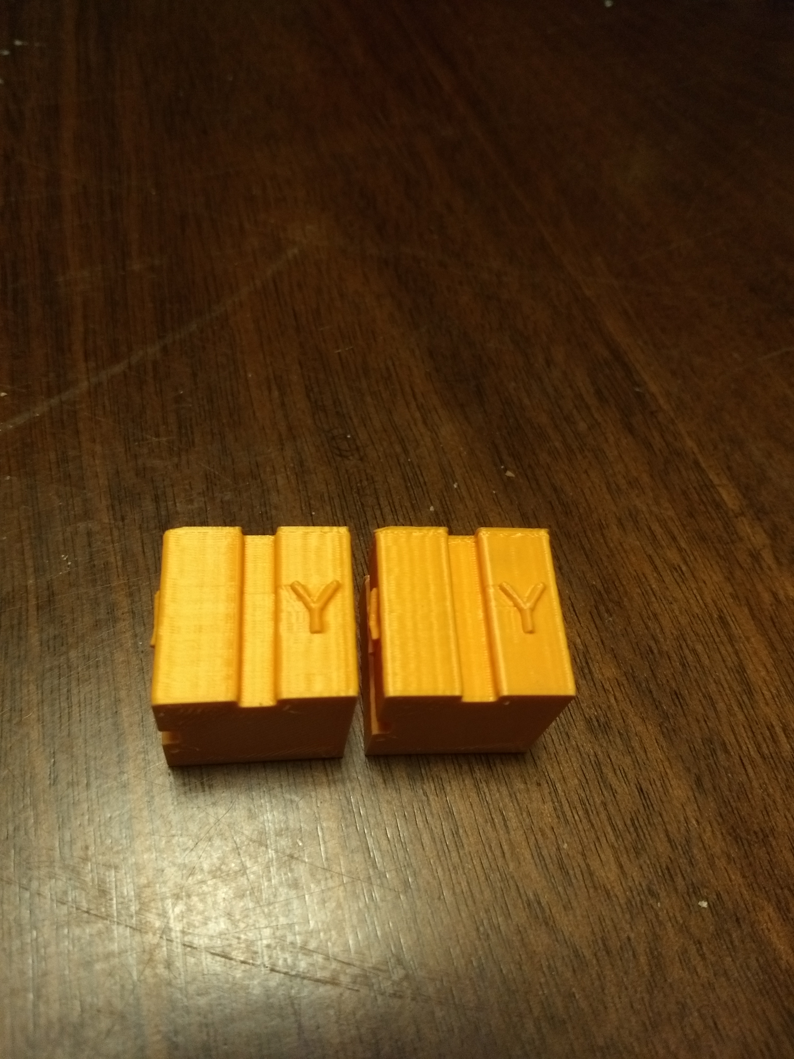
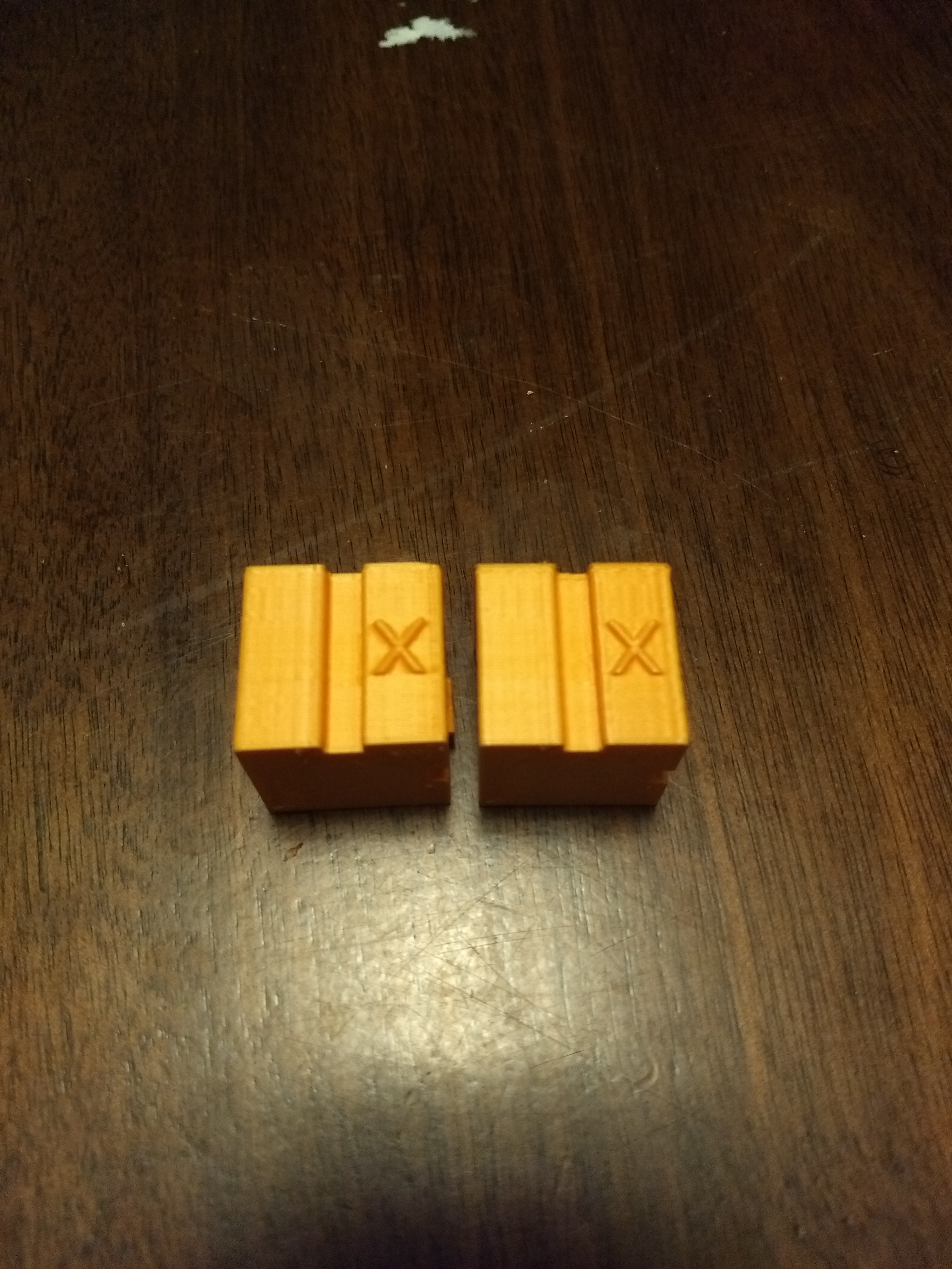
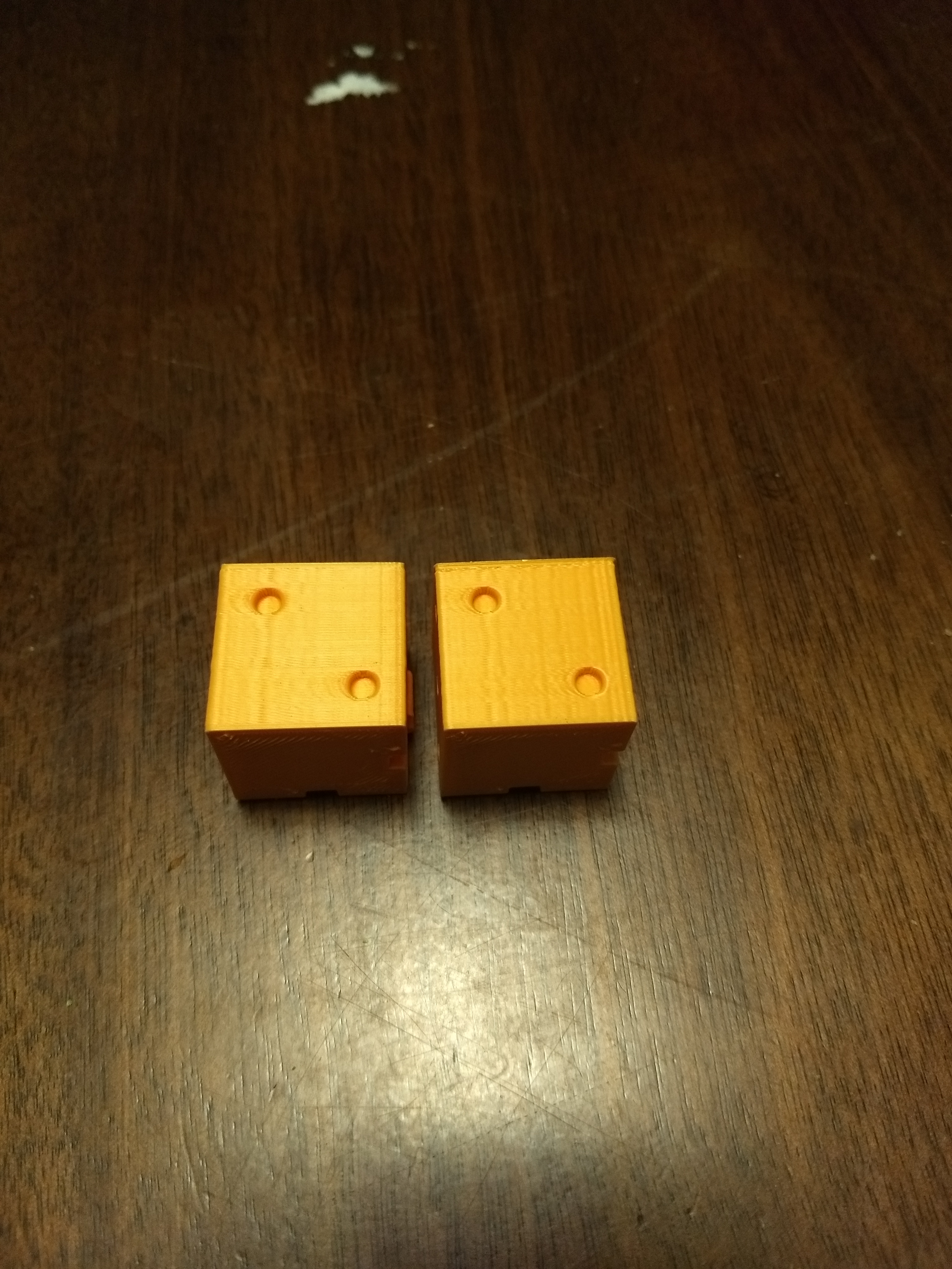
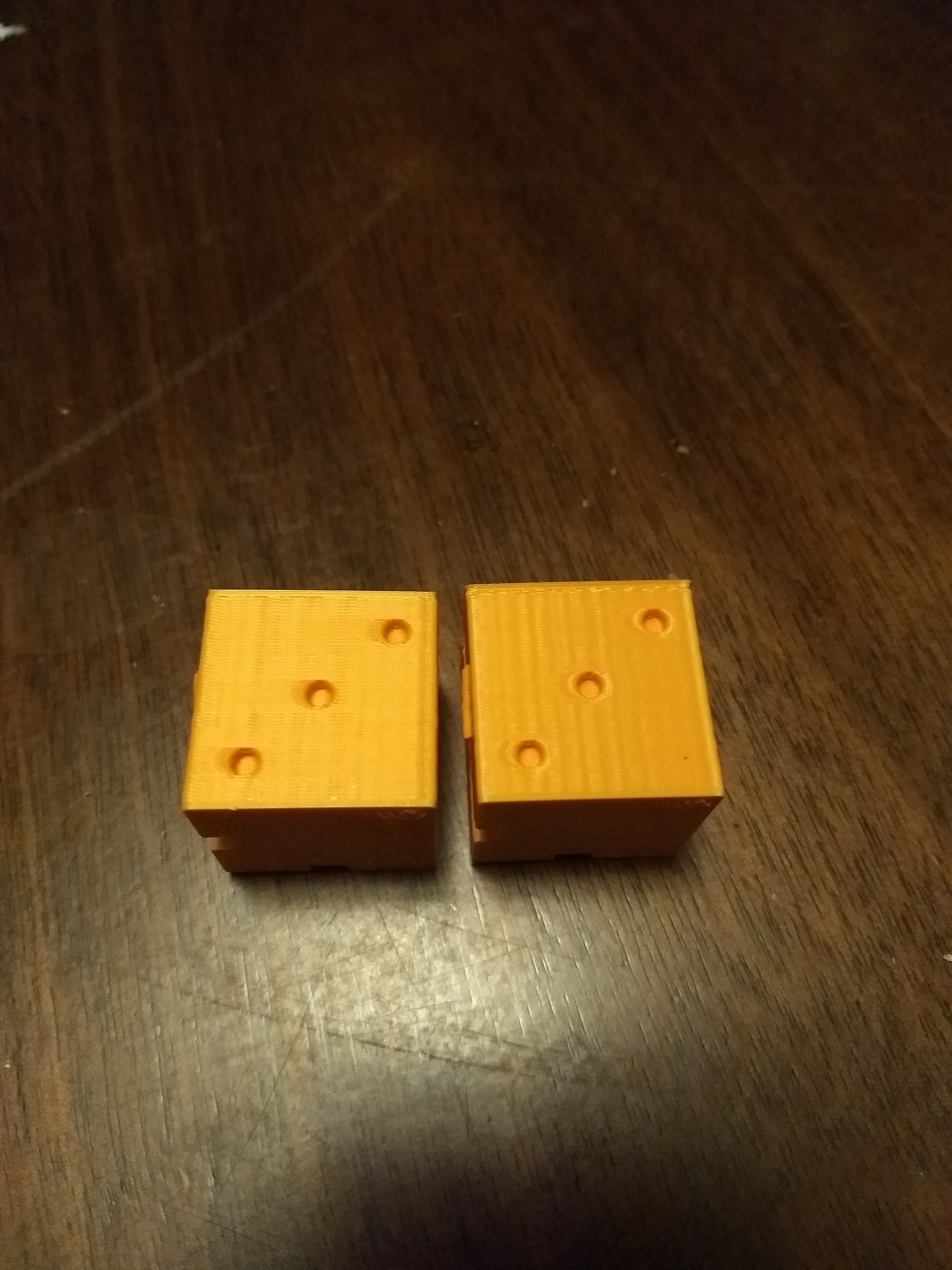
 chainsol
on 17 Jun 2018
chainsol
on 17 Jun 2018
I ran some "ringing" tests of the work-itersolve-20180609 branch with different acceleration orders on my makergear m2 printer. I couldn't perceive any significant difference with the bezier curve implementation. If anything, there may be a slight degradation in quality with it enabled.
It's possible I goofed on the bezier implementation. I've triple checked the code though, and all the unit tests look like it does what it is intended to do. If anyone spots something wrong, let me know.
The tests below were all done on a makergear m2 printer with pressure_advance=0.03, a layer height of 0.28mm, speed of 100mm/s (outer perimeter speed of 50mm/s).
These cubes are with accel=3000, junction_deviation=0.02. From left to right is accel_order=6, accel_order=4, accel_order=2, and a run from the master branch (which should be identical to accel_order=2):
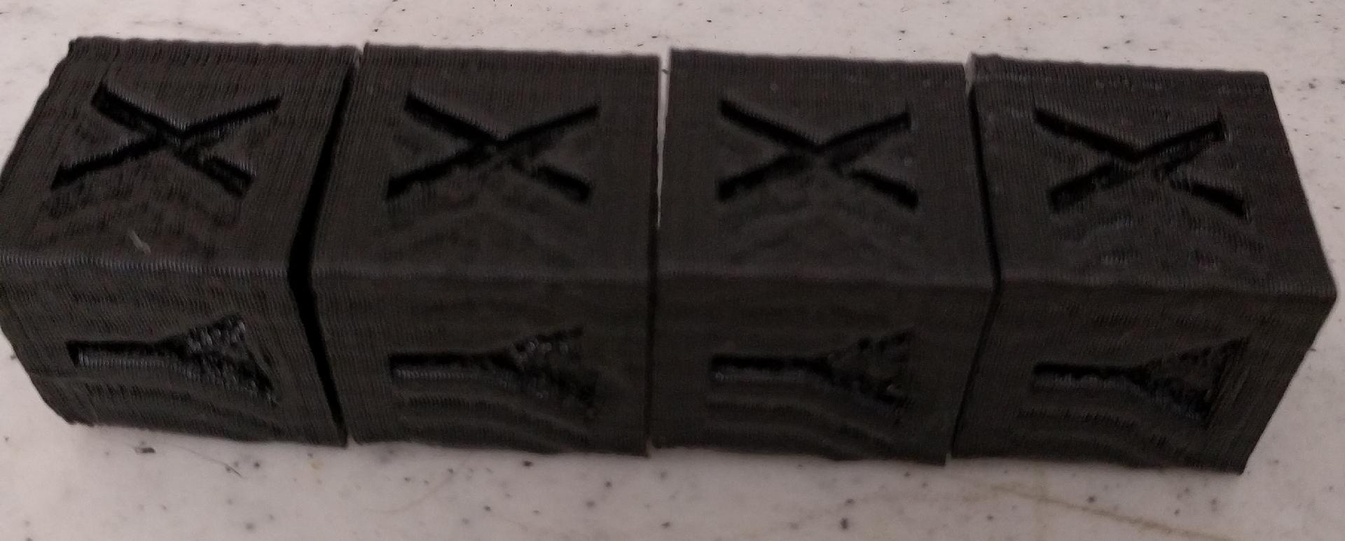
These cubes are with accel=2000, junction_deviation=0.005. From left to right is accel_order=4, accel_order=2:
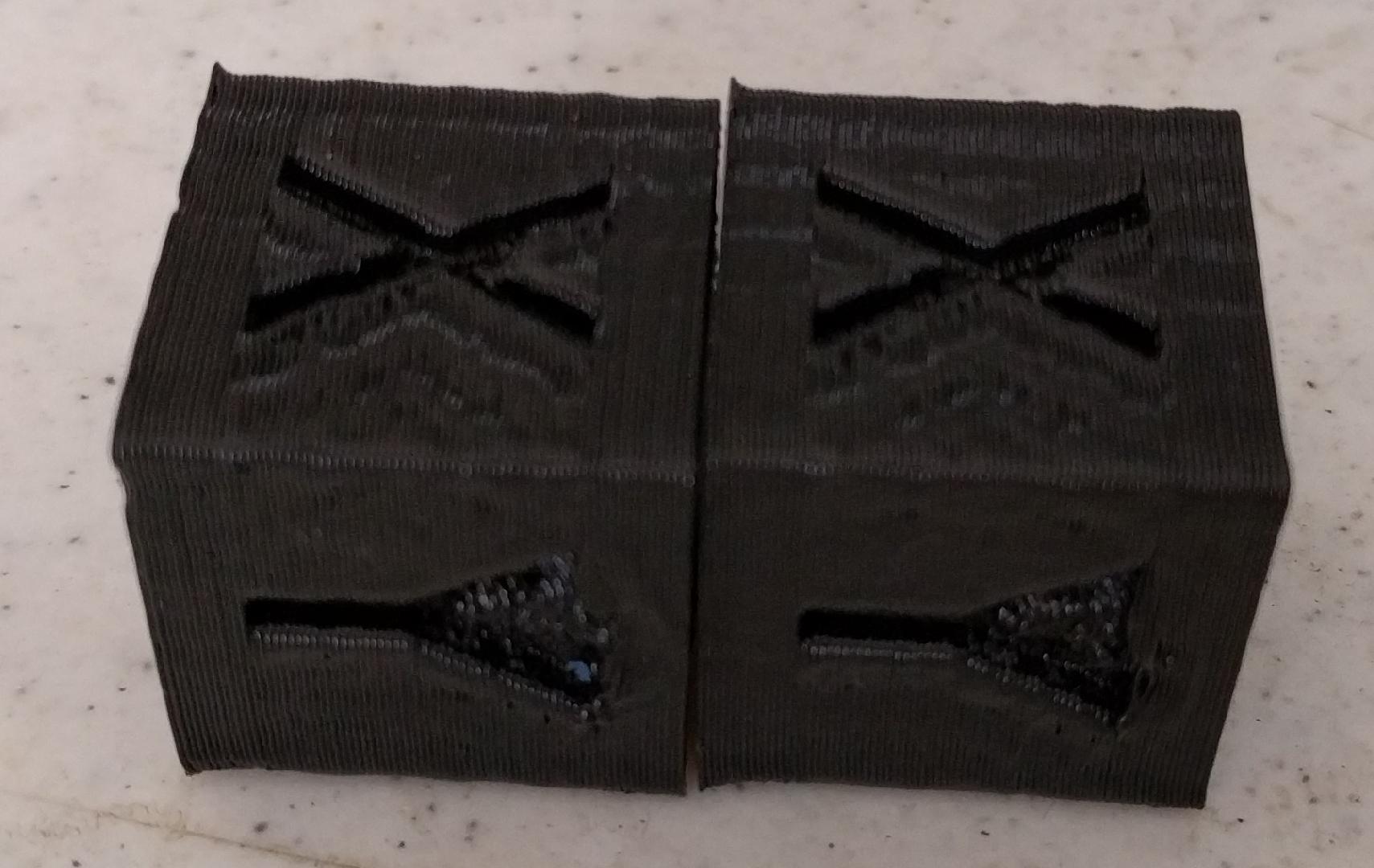
These cubes are with accel=1000, junction_deviation=0.005. From left to right is accel_order=6, accel_order=2:
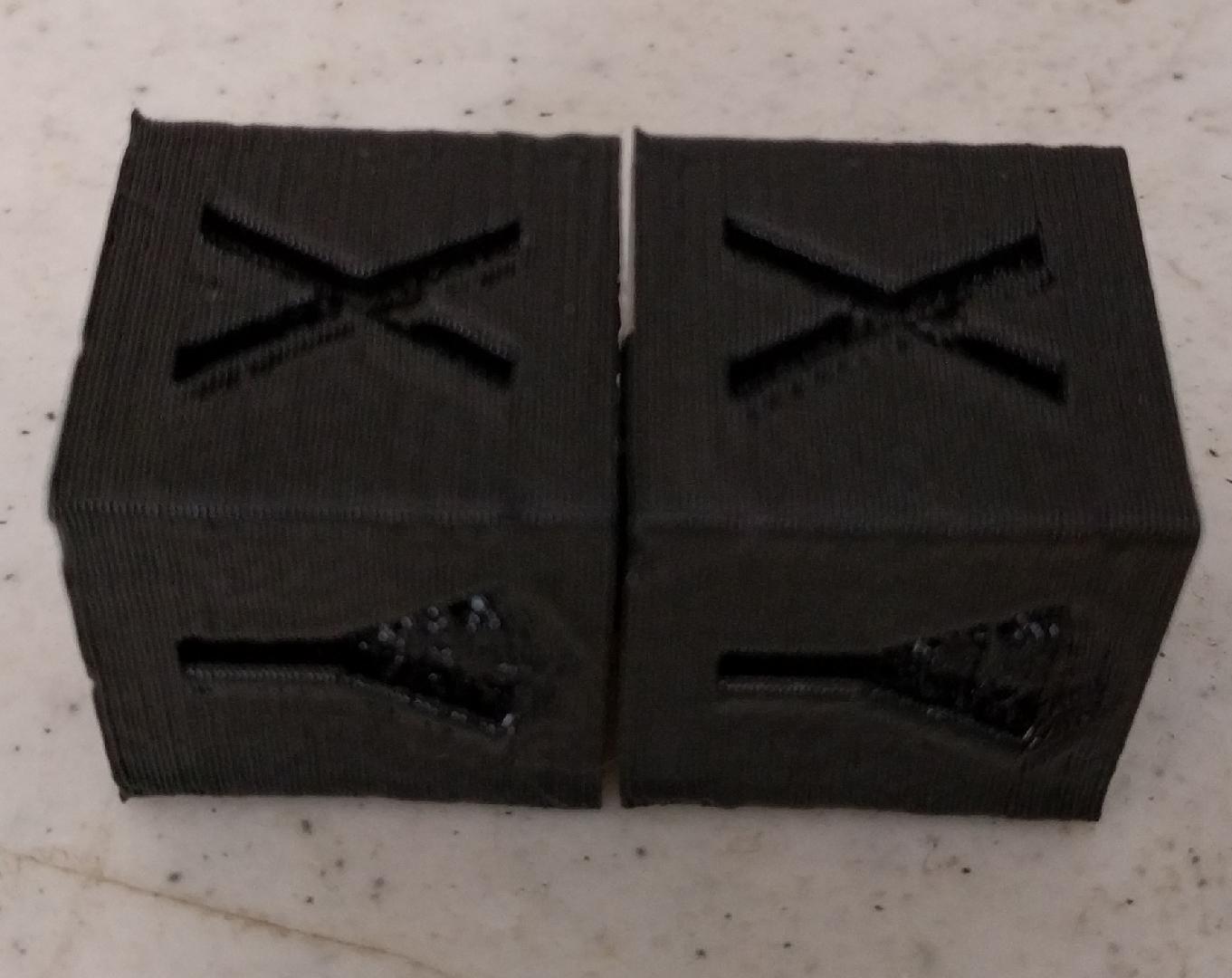
-Kevin
KevinOConnor
on 17 Jun 2018
@KevinOConnor, @chainsol: Your results seem more-or-less in line with what I've found.
There seem to be certain situations where the Bézier smoothing helps. For example, when printing a simple box, I could never get the corner ringing to go away completely with constant acceleration. Even when setting junction_deviation to zero, there was still (very subtle) ringing. With Bézier smoothing, the ringing becomes imperceptible in that particular situation. But when junction_deviation is not zero, it doesn't help as much. The velocity jumps at corners (as well as other factors, I'm sure) seem to contribute to ringing far more than the acceleration profile.
So... at this point I'm not convinced that the Bézier velocity smoothing is all that useful for typical 3D printers (except maybe in a few specific cases). Maybe a "real" 3rd-order (constant jerk) motion planner would be an improvement, but I'm not sure it's worth the effort and extra code complexity.
bmc0
on 18 Jun 2018
Also, I haven't found any cases where there was a decrease in print quality with my printer, but that may be because I had extruder lookahead disabled.
bmc0
on 18 Jun 2018
@KevinOConnor @bmc0 @chainsol
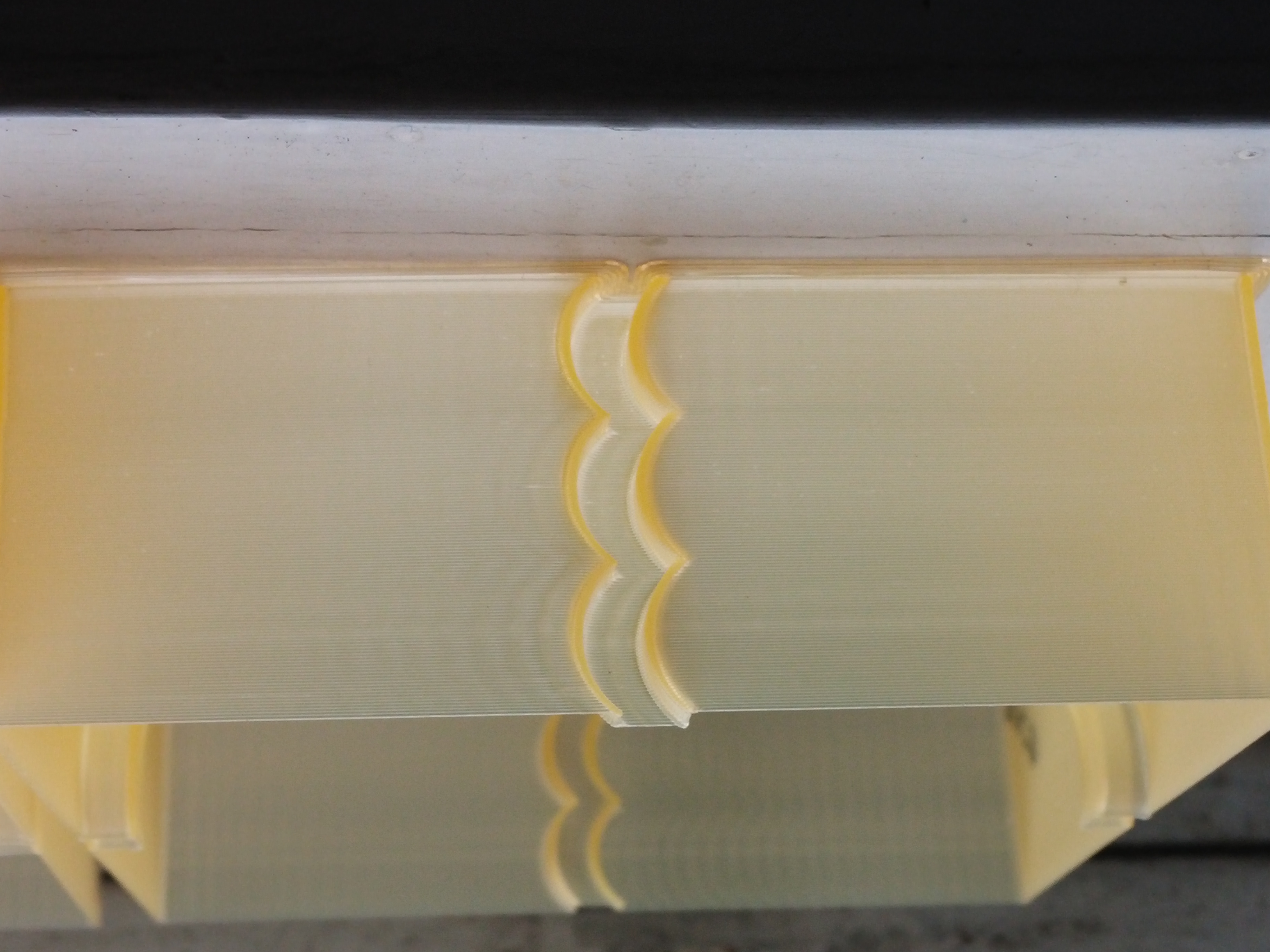
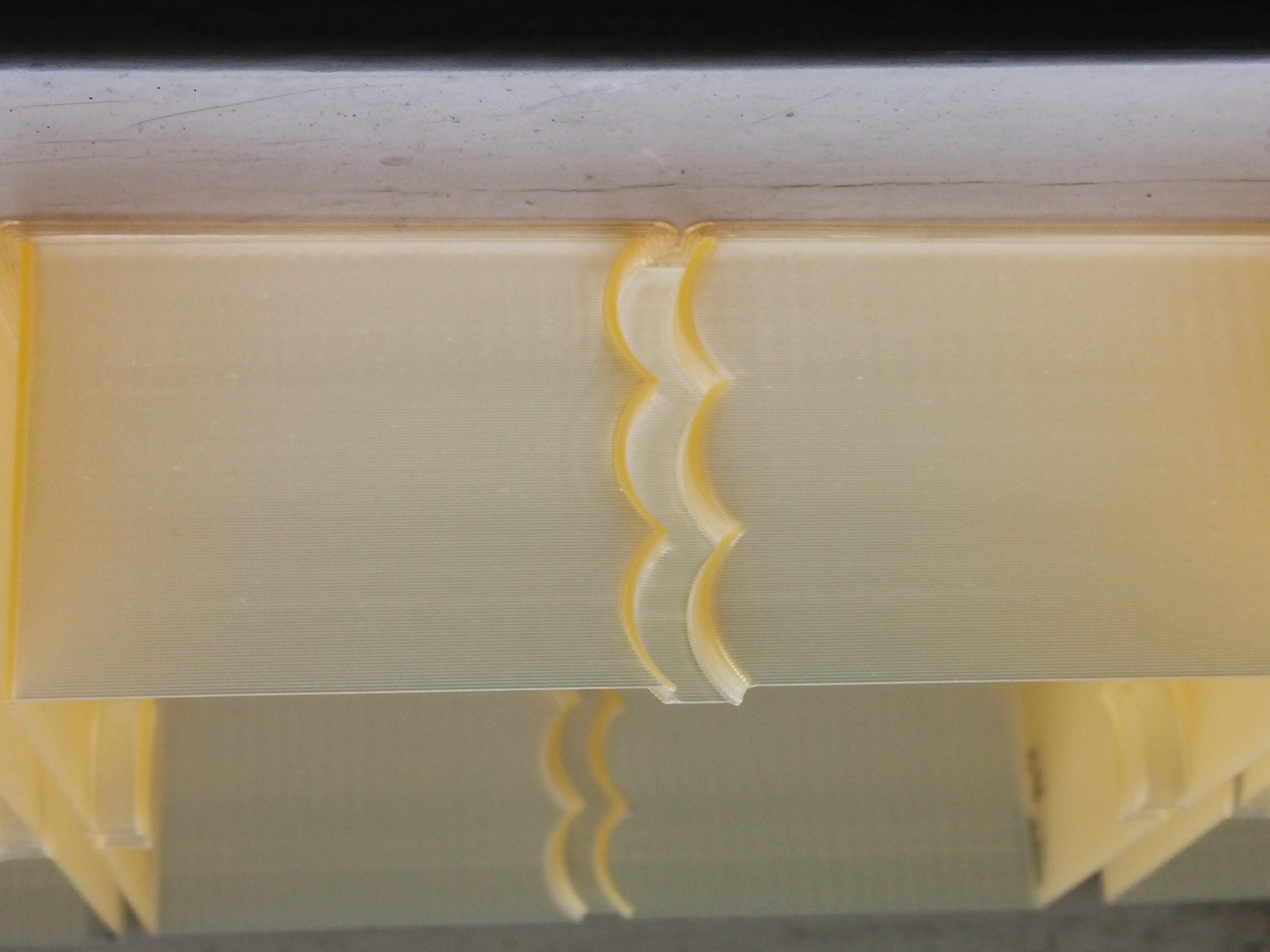
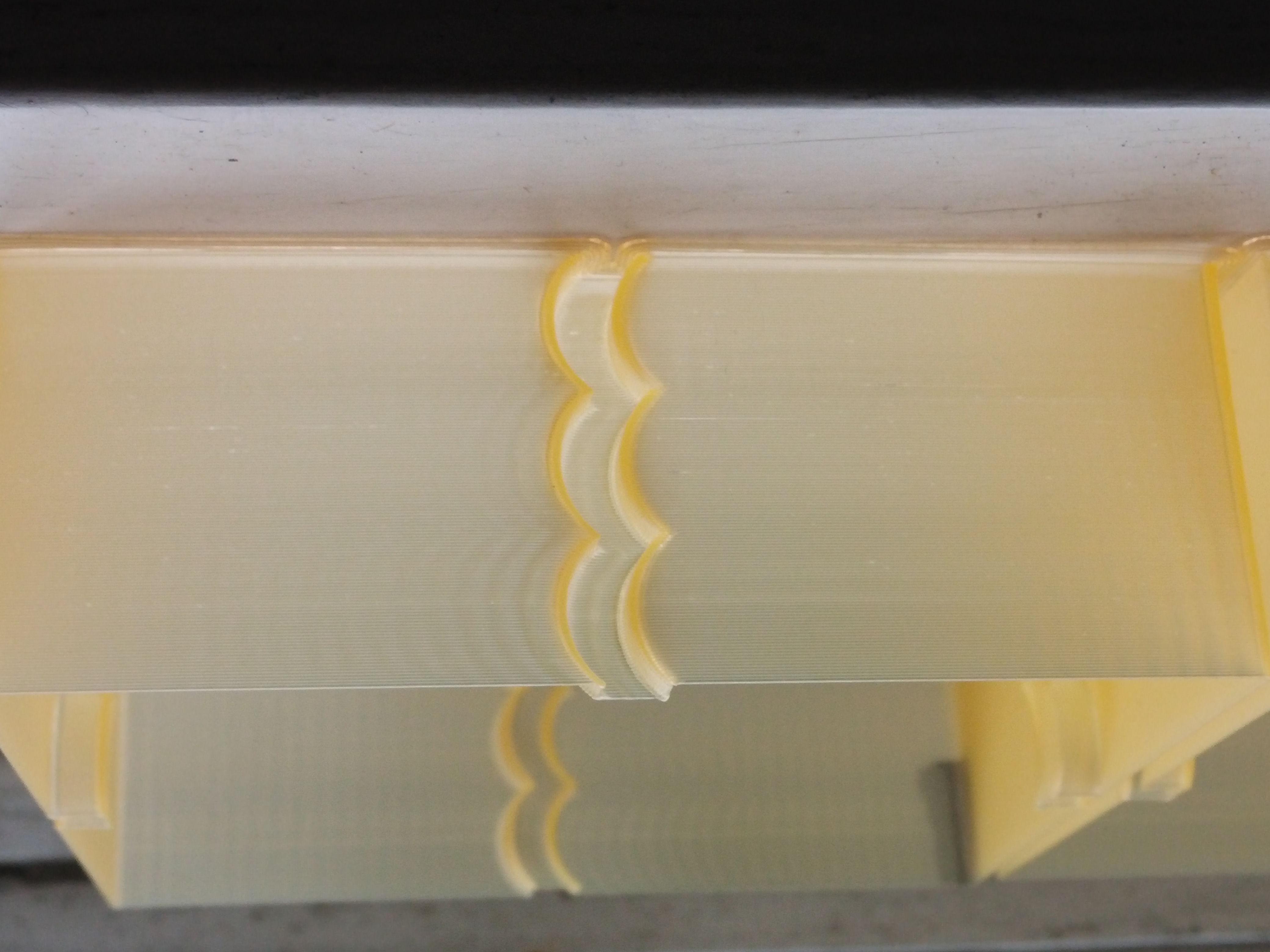
First up the ringing in the prints is from a GT2 belt running over a smooth idler in my opinion and not from klipper, it is hard to see in the pics my camera is not so good.
I have changed acceleration every 10mm starting at 1000 ,2000, 3000 the print is 30mm high.
one print is bmc0 scurve 6th order,
one is Kevin's Constant Acceleration
and one is Kevin's scurve 6th order.
The constant Accel has noticable ringing from start to finish, the scurve at 1000 is less ringing then constant accel at 1000
The other thing I noticed was print times
bmc0 was 19:37
kevins was 19:23
CA was 19:41
BlackStump
on 18 Jun 2018
@BlackStump: The print times should be exactly the same since the actual move time isn't changed by the smoothing. Do those print times include extruder/bed warm up?
My code and @KevinOConnor's code appear to have produced exactly the same result, which is good.
bmc0
on 18 Jun 2018
@bmc0 it was the print completion time in Octoprint and I have extruder/bed heating before print head movement, how accurate those times are from Octoprint I do not know.
S3D said 12 minutes when I sliced it
Octoprint estimated 13 minutes
ringing_test_30mm_A1_3.zip
I have included the gcode if your interested
BlackStump
on 19 Jun 2018
On Sun, Jun 17, 2018 at 09:01:35PM -0700, BlackStump wrote:
First up the ringing in the prints is from a GT2 belt running over a smooth idler in my opinion and not from klipper, it is hard to see in the pics my camera is not so good.
I have changed acceleration every 10mm starting at 1000 ,2000, 3000 the print is 30mm high.
one print is bmc0 scurve 6th order,
one is Kevin's Constant Acceleration
and one is Kevin's scurve 6th order.
The constant Accel has noticable ringing from start to finish, the scurve at 1000 is less ringing then constant accel at 1000
Thanks!
If I understand correctly, you see better results with s-curves at
accel=1000? From the pictures, it looks like s-curves produce worse
results at accel=3000 (and possibly also at accel=2000).
The other thing I noticed was print times
bmc0 was 19:37
kevins was 19:23
CA was 19:41
That's odd - as @bmc indicates the times should be identical. Might
just be noise in the way OctoPrint measures the elapsed time. In any
case, an 18 second difference is pretty small.
-Kevin
KevinOConnor
on 19 Jun 2018
@KevinOConnor
I am actually doing some testing now to verify acceleration sweet spot for my printer with s-curve,
but you are correct 1000 was better then 3000.
if I just change acceleration it seems ACCEL_TO_DECEL is fixed at 1500 is that a expected result ?
The test I am doing now I am changing ACCEL_TO_DECEL to be half of acceleration
ie
SET_VELOCITY_LIMIT ACCEL=2000 ACCEL_TO_DECEL=1000 JUNCTION_DEVIATION=0.02 ACCEL_ORDER=6
BlackStump
on 19 Jun 2018
@KevinOConnor
Print details single perimeter 80mm/s (outer perimeter speed 80mm/s)
I changed parameters every 5mm
ie
13:55:58 max_velocity: 300.000000 max_accel: 1000.000000 accel_order: 6 max_accel_to_decel: 500.000000 junction_deviation: 0.002500(starting Value)
13:59:46 max_velocity: 300.000000 max_accel: 1000.000000 accel_order: 6 max_accel_to_decel: 500.000000 junction_deviation: 0.005000
14:02:30 max_velocity: 300.000000 max_accel: 1000.000000 accel_order: 6 max_accel_to_decel: 500.000000 junction_deviation: 0.007500
14:05:12 max_velocity: 300.000000 max_accel: 1000.000000 accel_order: 6 max_accel_to_decel: 500.000000 junction_deviation: 0.010000
14:07:55 max_velocity: 300.000000 max_accel: 1000.000000 accel_order: 6 max_accel_to_decel: 500.000000 junction_deviation: 0.015000
14:10:36 max_velocity: 300.000000 max_accel: 2000.000000 accel_order: 6 max_accel_to_decel: 1000.000000 junction_deviation: 0.002500
14:12:58 max_velocity: 300.000000 max_accel: 2000.000000 accel_order: 6 max_accel_to_decel: 1000.000000 junction_deviation: 0.005000
14:15:20 max_velocity: 300.000000 max_accel: 2000.000000 accel_order: 6 max_accel_to_decel: 1000.000000 junction_deviation: 0.007500
14:17:42 max_velocity: 300.000000 max_accel: 2000.000000 accel_order: 6 max_accel_to_decel: 1000.000000 junction_deviation: 0.010000
14:20:03 max_velocity: 300.000000 max_accel: 3000.000000 accel_order: 6 max_accel_to_decel: 1500.000000 junction_deviation: 0.002500
seems at 1000 accel changing Junction_deviation has little to no effect.
at 2000 there was ringing even with the lowest junction deviation and I think it was getting worse as junction deviation increased but marginal at best
The last 5mm was at 3000 accel at junction deviation of 0.0025 and was more pronounced when compared to the previous 5mm which was accel of 2000 and junction deviation of 0.01
I think what I am seeing is for this test junction deviation has little to no effect, acceleration certainly does. I am not really seeing a difference at the corners either.
If I get a chance tomorrow I will do the exact same test in constant accel mode.
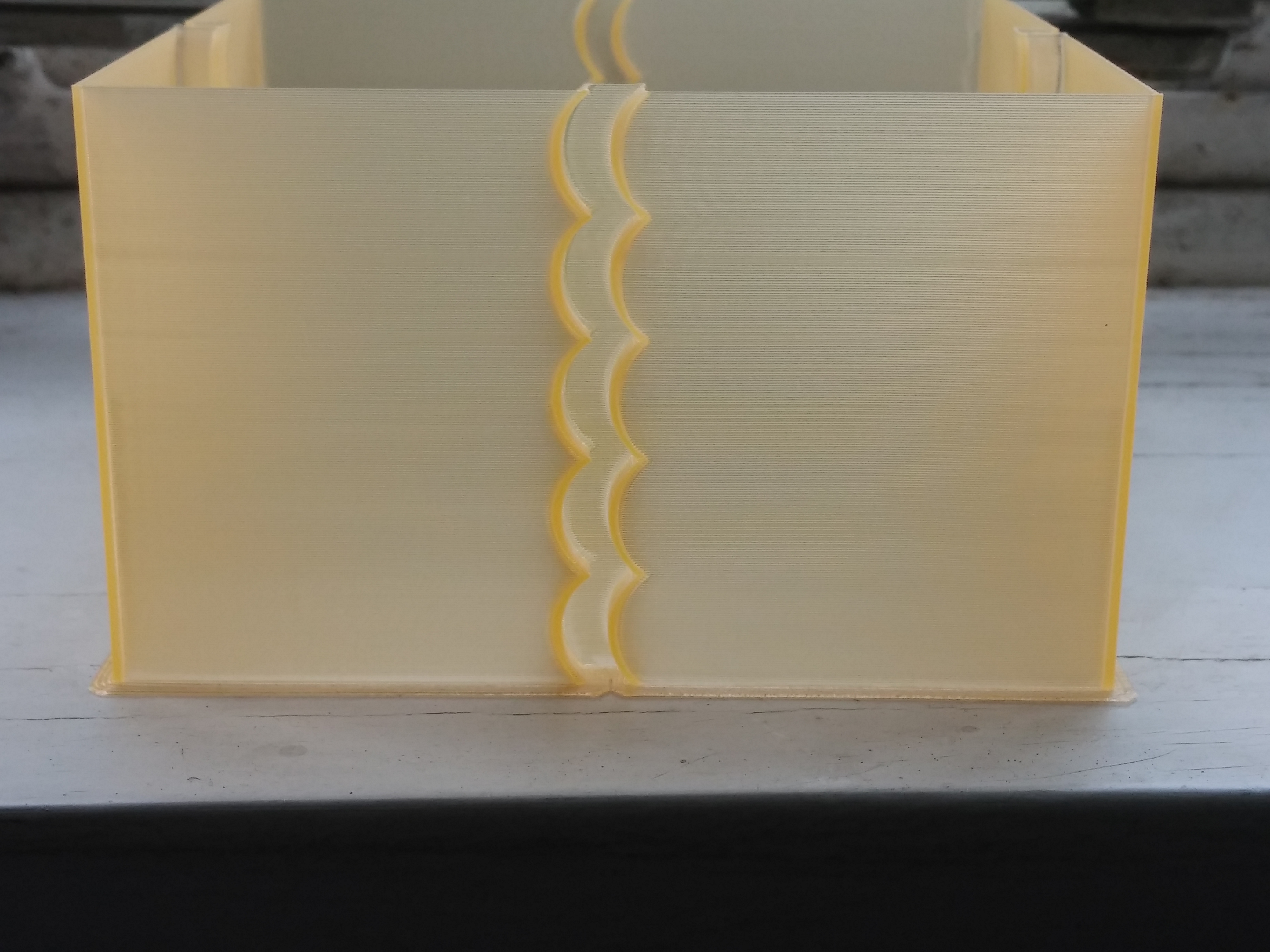
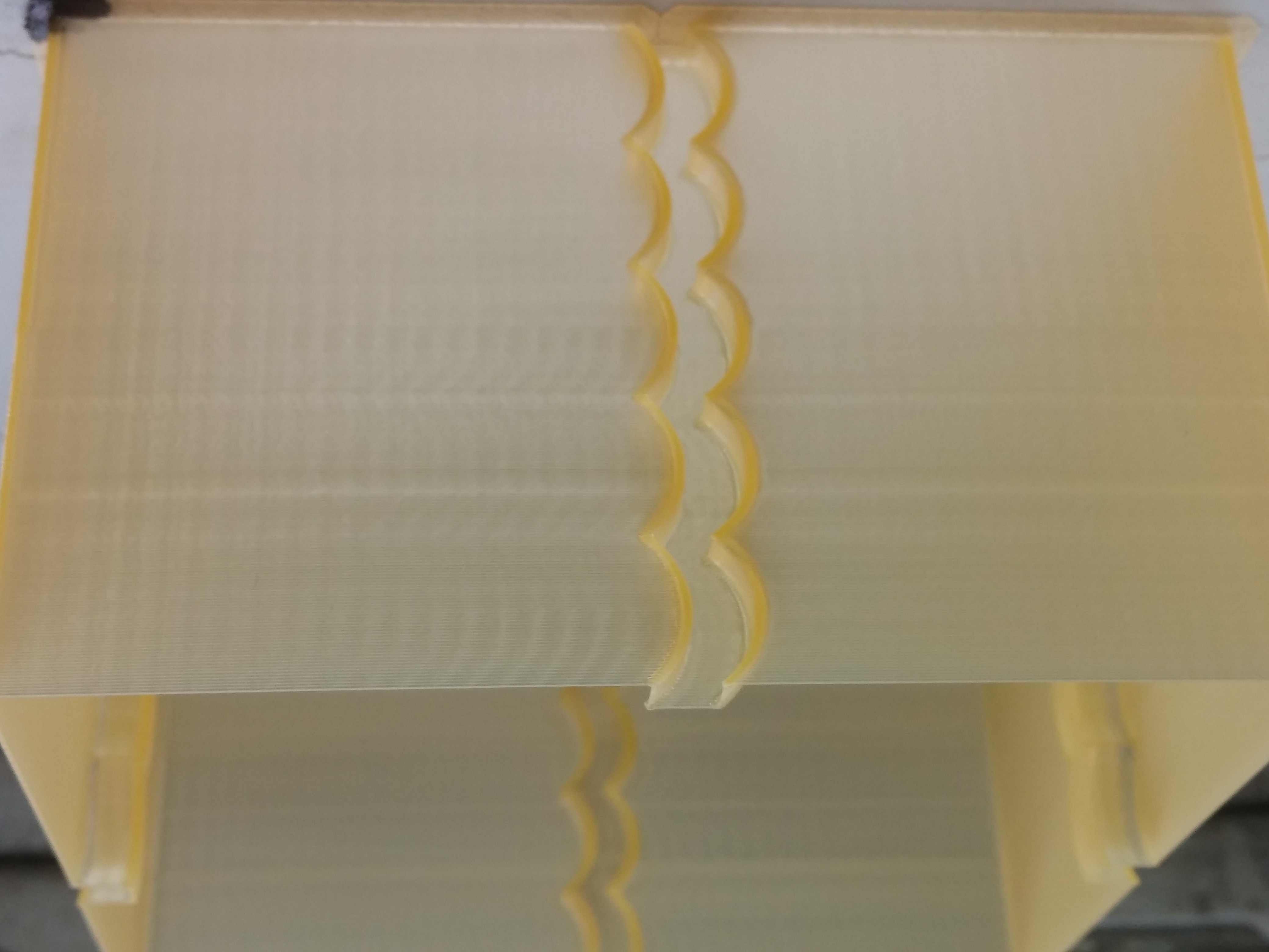
BlackStump
on 19 Jun 2018
Just checked the difference between current bezier curve and t-sin(t) speed profile. Not much difference, judge for yourself:
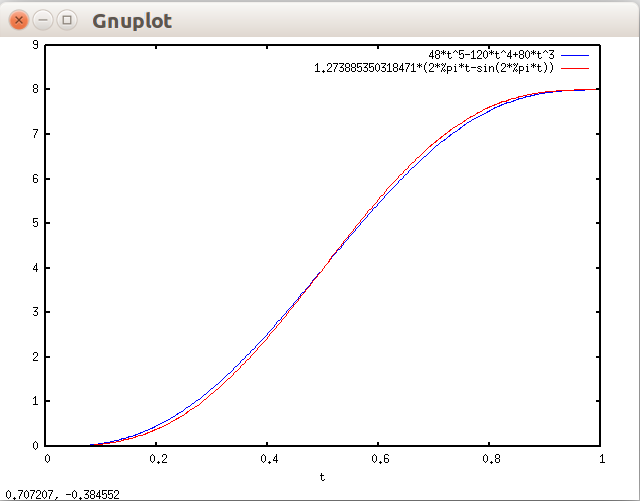
misan
on 20 Jun 2018
FYI, I've committed the iterative solver changes to the master branch. I have not committed the s-curve code to the master branch - it is now on its own test branch: work-scurve-20180620
-Kevin
KevinOConnor
on 20 Jun 2018
I'm going to summarize my current thoughts on the s-curve code.
As others have indicated, it's not clear to me that s-curves are compatible with junction_deviation. To wit, it may not make sense to be 3rd order smooth in a system that isn't 1st order smooth.
As near as I can tell from the reports in this thread, testing on the s-curve code has shown only minor print quality differences. It provides slightly worse results for some. I think it's been uniformly worse at higher accelerations (which is counter intuitive). Possibly some minor quality improvement on some machines at low acceleration.
So, my current plan is to leave the code on the work-scurve-20180620 branch. I would be curious to see the results from further print tests.
-Kevin
KevinOConnor
on 27 Jun 2018
@KevinOConnor I have continued to use your s-curve branch and the past print I did was a 2 hour print at 90mm/s and print quality was great and more importantly smooth in operation.
I think where S-curve will come into it's own is actually allowing faster print speed with great quality.
Of course hardware dependent. You cant make a silk purse out of a pigs ear to coin a phrase.
Yes I have dropped acceleration back to 2000 from 3000 but upped print head speed. For a budget Cartesian printer I am quite impressed with your S-curve branch and never thought I would be printing at that speed and admiring the quality.
I will continue to use and if merged into master all well and good, gives option to use or not use in any case I will be continuing to use.
I have plans and parts coming to change out the Allergro stepper drivers for TMC2100's so will be interesting to see what effect that has when using your s-curve branch.
BlackStump
on 27 Jun 2018
@BlackStump OFFTOPIC - don't buy TMC2100, go directly with 2130 or 2208 with are much better.
dragonnn
on 27 Jun 2018
or TCM2224
http://www.panucatt.com/product_p/sd2224.htm
regards
 bruce356
on 27 Jun 2018
bruce356
on 27 Jun 2018
My results have been as Kevin said - I saw some ringing issues that seem to have been caused by the s-curve acceleration. I printed a vase at 150mm/s with 6th order accelerations on, and then printed the same vase at 150mm/s with constant acceleration. The ringing was _greatly_ reduced on the constant acceleration print.
chainsol
on 27 Jun 2018
Can the effects of acceleration of the hotend/carriage be observed independently of the effects of acceleration on the extruder stepper?
w1ebr
on 27 Jun 2018
On Wed, Jun 27, 2018 at 12:32:41AM -0700, BlackStump wrote:
@KevinOConnor I have continued to use your s-curve branch and the past print I did was a 2 hour print at 90mm/s and print quality was great and more importantly smooth in operation.
I think where S-curve will come into it's own is actually allowing faster print speed with great quality.
Of course hardware dependent. You cant make a silk purse out of a pigs ear to coin a phrase.Yes I have dropped acceleration back to 2000 from 3000 but upped print head speed. For a budget Cartesian printer I am quite impressed with your S-curve branch and never thought I would be printing at that speed and admiring the quality.
I will continue to use and if merged into master all well and good, gives option to use or not use in any case I will be continuing to use.
I have plans and parts coming to change out the Allergro stepper drivers for TMC2100's so will be interesting to see what effect that has when using your s-curve branch.
@BlackStump, I appreciate you running the tests and reporting back the
results! I'm definitely still interested in scurves. I did want to
let people know that I'm not currently confident enough with the
current implementation to feel comfortable merging it. I am still
interested in hearing feedback and seeing test results, but I do
wonder if an alternative implementation would provide better results.
Or, if an alternative testing methodology would better highlight the
effect of scurves.
Thanks,
-Kevin
KevinOConnor
on 28 Jun 2018
@KevinOConnor I agree that devising a testing method that better highlights scurves is important because I am not convinced that the ringing I am seeing is a sole product of scurves.
I have suspicion that direct drive extruder has a influence and in the next few days I intend to change from direct drive to 3:1 reduction to see if I can confirm that suspicion.
BlackStump
on 28 Jun 2018
I remember a foto tuning program: you took a foto, the program calculated 10 possible filtering methods. You decided which looks best. The program took the best result and made 10 new fotos by applying new 10 filtering methods, you choose, and so on.
Is it possible to use this method to produce 10 3d prints with different methods (s-curve, bezier, etc.) and the user decides which one to take? Then new 10 methods, etc. This will result in the best method being used for your specific printer setup (Direct Drive / Bowden, Delta/CoreXY, stable/unstable cheap etc.).
Then store the used methods as configuration setting.
Later the optimizing results of all users can be compared and recommended values for specific printer setups (construction, nozzle, filament, print speed/accel....) can be derived.
 JoergS5
on 28 Jun 2018
JoergS5
on 28 Jun 2018
It's a good idea, but it won't work if the best method mainly depends on the object being printed.
 FeepingCreature
on 28 Jun 2018
FeepingCreature
on 28 Jun 2018
You mean for different objects there are different best methods? Yes, I agree, and what is "worse", what is the best object? One user wants to print fast, quality irrelevant, the next wants maximum stability of the object, the next best print quality, next weight. Or mixing them inside the object. For finding the best method, the different parameters must be defined, then you can optimize. Input parameters (physical properties of printer, filament ...) and output (end result, time ...). A good physical model and a good simulation tool would be useful.
My proposal was to use an evolutionary approach of continuous improvement und build this idea into the firmware / slicer (you can change firmware on fly with scripting engines, additionally).
JoergS5
on 29 Jun 2018
Sorry to be just "chiming in" but as someone interested in s-curve but
unable to test at the moment, I wanted to suggest where I expect s-curve to
be most valuable. I believe it will be most valuable in stiff systems, so
leadscrew driven systems. The belts, especially most reprap belts, will
stretch and smooth the behavior of standard linear acceleration profiles.
Leadscrew dont really do that.
Cant wait to test the s-curve implementation but am a couple months away
from working on my stiff printer again.
On Friday, June 29, 2018, JoergS5 notifications@github.com wrote:
You mean for different objects there are different best methods? Yes, I
agree, and what is "worse", what is the best object? One user wants to
print fast, quality irrelevant, the next wants maximum stability of the
object, the next best print quality, next weight. Or mixing them inside the
object. For finding the best method, the different parameters must be
defined, then you can optimize. Input parameters (physical properties of
printer, filament ...) and output (end result, time ...). A good physical
model and a good simulation tool would be useful.My proposal was to use an evolutionary approach of continuous improvement
und build this idea into the firmware / slicer (you can change firmware on
fly with scripting engines, additionally).—
You are receiving this because you are subscribed to this thread.
Reply to this email directly, view it on GitHub
https://github.com/KevinOConnor/klipper/issues/57#issuecomment-401254147,
or mute the thread
https://github.com/notifications/unsubscribe-auth/ACo_ZNo3HjXJe7AUM3giE9TG_mBLlVC-ks5uBb9pgaJpZM4RCeS3
.
--
Tomek Brzezinski Mechanical Engineer B.Sc, Duke
University, December 2014
60 edgemere rd Interests: ,
Electromechanics, Embedded systems, Data Acquisition, Fabrication Tech, EV
Tech
Lynnfield, MA,01940 Skills: Cadwork, AVR custom
design, 3D Printing, C++, Custom PCB fab.
 TomekBrz
on 29 Jun 2018
TomekBrz
on 29 Jun 2018
This thread has been getting a bit out of control and hard to follow as I am just jumping in, so bear with me.
Like Tomek suggested, I have a fairly rigid printer, full linear rails with two screws for the Z-axis. I normally have to tune down the jerk and leave accel at default in marlin to get good results. The current version of klipper has been a bit of a mixed bag for me because on the one hand I have seen large print quality improvements but the constant accel has made ringing in my prints horrific. Ironically the better overall quality has made the ringing stick out more than it did before.
I tried the Scurve branch yesterday, and wow what a difference it made.
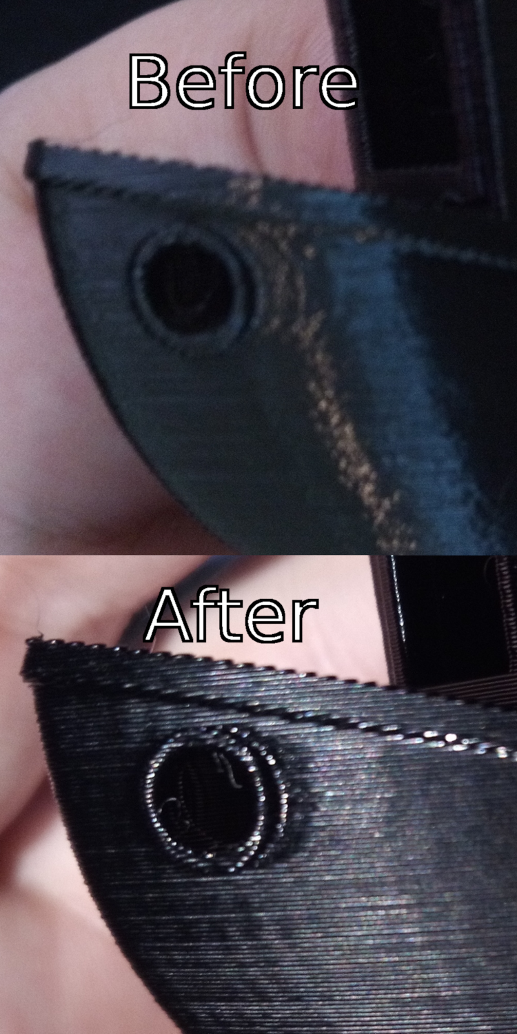
(Sorry about the quality, I might try later with my SLR)
While standard klipper is worse than marlin for me in terms of ringing, S-curve klipper gives me the best results I have ever had.
A few interesting things to note:
- Nothing was changed between those models except klipper.
- The before picture with ringing had accel already tuned down to 600 in stock klipper just to get it to that level.
- I was printing PETG with the normal settings I use, but this particular PETG seems to want to be printed hotter and everything that was printed very slightly too cold turned matte instead of glossy. From this I noticed that places that would cause ringing are dwelled on and heated much longer, which is now causing different artifacts. In the after image it almost looks like there is still some ringing, but there isn't, it just that the plastic where the ringing would be is now discolored and glossy while everything else is matte It might be possible the degradation other people are seeing is from this heating quirk canceling out any benefit they would have gotten.
So are we going to get S-curve PID or fan control next? 😂
 HorseEars
on 15 Jul 2018
HorseEars
on 15 Jul 2018
I tried the Scurve branch yesterday, and wow what a difference it made.
Thanks! Can you post what the max_accel, junction_deviation, max_accel_to_decel, pressure_advance, and any other relevant sections were from both the before and after versions? Also, what software versions did you use for the before and after prints?
-Kevin
KevinOConnor
on 15 Jul 2018
what software versions did you use for the before and after prints?
Both were the latest versions of stock and the s-curve branch as of yesterday, I think 0.6.0 and 0.6.0-170-g90ec7e1.
Can you post what the max_accel, junction_deviation, max_accel_to_decel, pressure_advance, and any other relevant sections were from both the before and after versions?
max_velocity: 400 max_accel: 600 junction_deviation=0.002 accel_order: 6 pressure_advance: 0.14
Everything else was default, I just took my old config and flashed the s-curve branch. I need to spend more time running some tuning tests.
Aren't you from central Texas @KevinOConnor ? I could loan you my printer for a while if it would help work on this as it seems like it's one of the only ones here that sees a change.
HorseEars
on 15 Jul 2018
On Sun, Jul 15, 2018 at 12:24:35PM -0700, HorseEars wrote:
what software versions did you use for the before and after prints?
Both were the latest versions of stock and the s-curve branch as of yesterday, I think 0.6.0 and 0.6.0-170-g90ec7e1.
Can you post what the max_accel, junction_deviation, max_accel_to_decel, pressure_advance, and any other relevant sections were from both the before and after versions?
max_velocity: 400 max_accel: 600 junction_deviation=0.002 accel_order: 6 pressure_advance: 0.14
Everything else was default, I just took my old config and flashed the s-curve branch. I need to spend more time running some tuning tests.
Okay, thanks. FYI, I've rebased the work-scurve-20180620 branch on
top of the most recent code - including the square_corner_velocity
change. Hopefully this will make it easier to tune parameters.
Aren't you from central Texas @KevinOConnor ?
No, I'm in the US North East.
-Kevin
KevinOConnor
on 17 Jul 2018
Sorry for bumping an older issue. I just want to report back that i used the work-scurve-20180620 branch on one of my printers for 5 weeks now. I had no issues so far. Are you going to merge scurve into master some day?
@KevinOConnor
 ghost
on 30 Aug 2018
ghost
on 30 Aug 2018
Some people report small improvements with s-curves and some report a degradation. In order to merge this I think we would have to understand when and how it improves prints on real world printers. We'd then need to put together a simple guide (something like docs/Pressure_Advance.md) so that other users could know when to apply it, what to set it to, and what to look for.
-Kevin
KevinOConnor
on 30 Aug 2018
@KevinOConnor
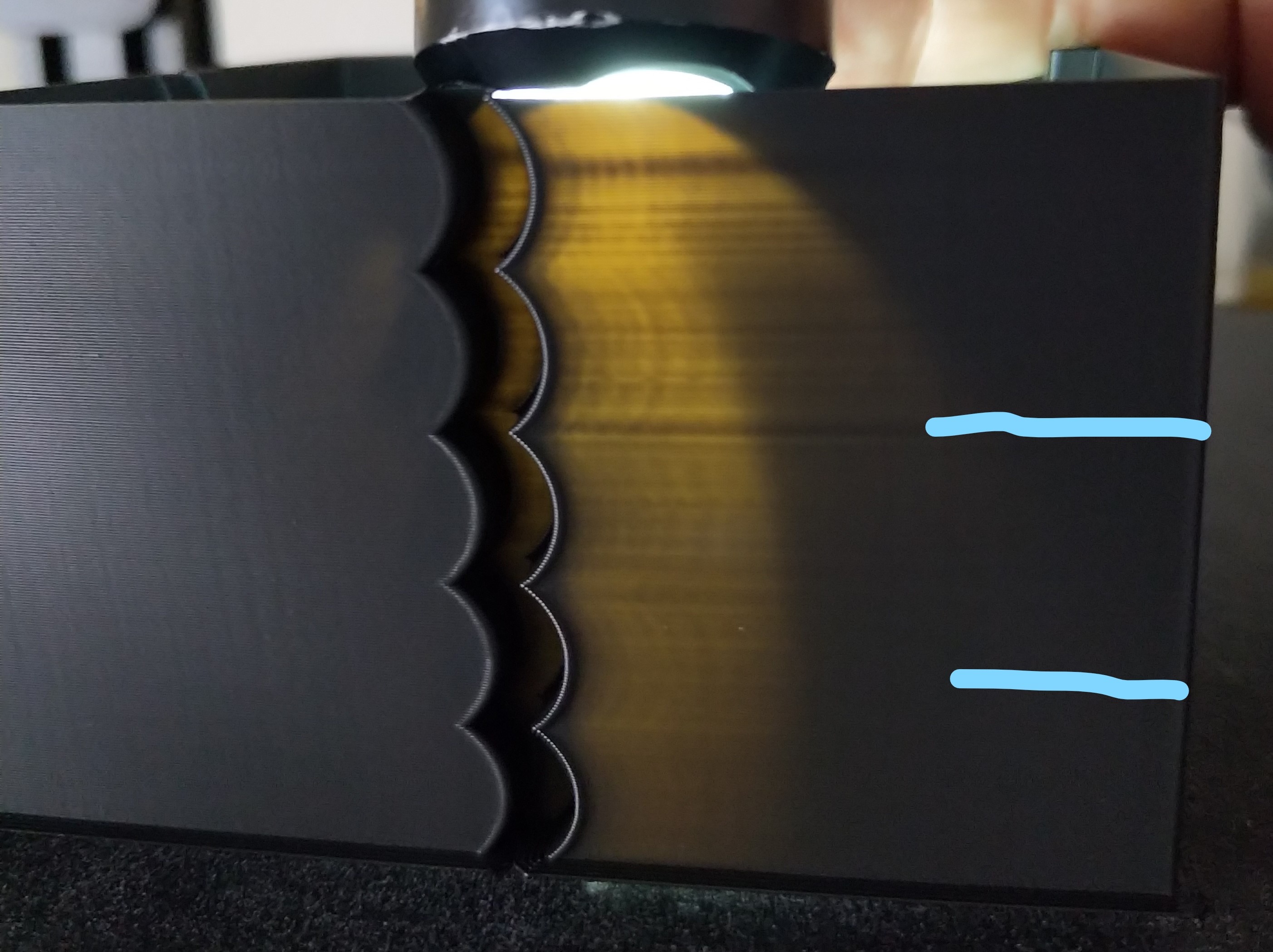
so I did another test print starting at accel_order: 6 then 4 then 2
ie
12:46:54 max_velocity: 300.000000 max_accel: 1315.000000 accel_order: 6 max_accel_to_decel: 1315.000000 square_corner_velocity: 4.500000
12:50:29 max_velocity: 300.000000 max_accel: 1415.000000 accel_order: 6 max_accel_to_decel: 1415.000000 square_corner_velocity: 4.500000
12:53:00 max_velocity: 300.000000 max_accel: 1515.000000 accel_order: 6 max_accel_to_decel: 1515.000000 square_corner_velocity: 4.500000
12:55:29 max_velocity: 300.000000 max_accel: 1315.000000 accel_order: 4 max_accel_to_decel: 1315.000000 square_corner_velocity: 4.500000
12:58:01 max_velocity: 300.000000 max_accel: 1415.000000 accel_order: 4 max_accel_to_decel: 1415.000000 square_corner_velocity: 4.500000
13:00:32 max_velocity: 300.000000 max_accel: 1515.000000 accel_order: 4 max_accel_to_decel: 1515.000000 square_corner_velocity: 4.500000
13:03:01 max_velocity: 300.000000 max_accel: 1315.000000 accel_order: 2 max_accel_to_decel: 1315.000000 square_corner_velocity: 4.500000
it goes on for same accel changes as 4 and 6
on the print the ringing is subtle and not so easy to see the light behind does help to highlight the ringing but in this test I would say 2 is worst and 6 is best but in any case the ringing is there for all accel orders.
I would have thought there would be ringing on the de-accel but seems to be only accel
BlackStump
on 15 Sep 2018
These guys used a filtered B-spline curve: https://www.youtube.com/watch?v=6sN71fx9frk
https://news.engin.umich.edu/2017/10/3d-printing-gets-a-turbo-boost-from-u-m-technology/
 propeller3D
on 1 Oct 2018
propeller3D
on 1 Oct 2018
Here is a link to their study: https://www.sciencedirect.com/science/article/abs/pii/S0957415817301277
I don't have access to the full study so I can read but they seem to use some kind of lookahead and calculate the movements to compensate for the vibrations that are about to occur.
propeller3D
on 1 Oct 2018
propeller3D
on 1 Oct 2018
@propeller3D That's a really good approach but you need a dynamics model of the printer to use it. A large printer manufacturer could probably hire someone to do that, but I don't think it's practical for hobbyists & one-off builds.
I do imagine there's a way accelerometers could be used to automatically build the dynamics model.
rcarlyle
on 1 Oct 2018
By the way, dc42 / David Crocker (RepRapFirmware dev) has been looking at S-curve motion and seems to have determined that resonant effects from the accel loads entering/exiting corners are more important to print quality than whether you use trapezoid or S-curve velocity. Specifically, by changing the duration of the deceleration phase entering the corner relative to the resonant frequency of the drivetrain, you can massively change the ringing. People have shown with print quality tests (changing accel settings mid-print) that there are very clear "sweet spots" where higher acceleration or higher speed leads to MUCH LESS ringing.
It's still not 100% clear the best way to take advantage of this corner resonance tuning idea -- different types of print geometry lead to different amounts of corner speed slowdown relative to command feedrate, so the duration of the decel/accel phases will vary somewhat. You can almost completely eliminate ringing for one type of corner geometry but a different shape could bring it back.
rcarlyle
on 1 Oct 2018
And I suspect a lot of the variation people here are seeing with S-curve velocity improving/worsening print quality are coming from inadvertent resonant tuning. If you turn on S-curve and accidentally hit a decel duration that amplifies ringing, you'll get worse results.
What people are doing with their RRF experiments is inserting acceleration change gcodes every so many layers into test prints. Like you try 500, 1,000, ... 5,000 mm/sec accel for 5mm height each, then change speeds and repeat. This sweeps the accel,speed space to find good combinations.
rcarlyle
on 1 Oct 2018
I do imagine there's a way accelerometers could be used to automatically build the dynamics model.
Indeed, they do exactly this:
The FRFs (Frequency response Functions) are measured by applying swept sine acceleration signals (with amplitudes ranging from 1.5 m/s2 to 3.0 m/s2 ) to the printer’s stepper motors (each having 12.5 μm stepping resolution) and measuring the relative acceleration of the build platform and print head using accelerometers (PCB Piezotronics 393B05 and Kistler 8704B100). The resonance peaks of the FRFs increase with decreasing input amplitude.
mabl
on 1 Oct 2018
@mabl Shows me for not re-reading the paper. (Saw it a year ago.)
I would tentatively suggest that the approach in the paper is a fundamentally different approach from the subject of this thread and would merit creating a new issue to discuss. It's using B-splines with a component transverse to the desired trajectory, which is a very different approach from the tangential-only velocity/accel/jerk focus in all the GRBL-derived printer control schemes.
rcarlyle
on 1 Oct 2018
If you know the speed/accelleration and you measure the distance between the ghosting/waves. Shouldn’t it be possible to calculate the resonant frequency of the vibrations from the printer and apply the correct acceleration to avoid those resonating vibrations from forming? I do it all the time manually when operating cranes at work. When you start/stop the crane you will get swinging of the load. However with experience I can come to a full stop without it continuing to swing. You do it by decellerating a little and watch the load swing forward and then when it’s about to swing back you catch up with it so the full stop is timed when the wire is perfectly vertical. I guess this would mean that you would use different acceleration/deceleration speeds depending on the speed the printer is at before it’s about to decellerate.
propeller3D
on 1 Oct 2018
@propeller3D If you're saying have the firmware automatically adjust accel/speed to avoid a known resonant frequency, then yes, David Crocker is attempting that now. His beta code (last month?) didn't work but it seems like a promising approach.
If you're saying the firmware should do like crane operators do (moving the crane over the swinging load to kill the pendulum potential energy) then that WOULD work if the firmware did it, and is kinda sorta what the U-Michigan paper is automating with a dynamics model. But isn't compatible with the way Klipper (or Marlin, Smoothie, RRF, etc) do motion control. All the GRBL-derived motion controllers exactly follow the commanded straight-line trajectories and don't have any ability to deviate from that path. If you're willing to deviate from the path (like MachineKit does) then you can do all sorts of new things, like round off sharp corners with small radii to eliminate corner jerks / velocity jumps. One of the things you could do is add a transverse motion component to the corner exit region to counteract ringing.
rcarlyle
on 1 Oct 2018
I’m saying the first thing. Start the deceleration with the correct timing and decelleration amount to kill the resonance just in time for the stop.
Do you have a link, that does sounds very promising?
Crane operators basically do that. Time the accel/decellerations to kill swinging. At least I do that. I have 4 different speeds so I can sort of control how fast it decellerates/accelerates. There are cranes that do this automatically. Maybe someone could do some research into how they do it.
propeller3D
on 1 Oct 2018
The problem with the crane comparison is you're not really positioning like a 3d printer is - you can overshoot or undershoot and move back to position in a crane, but a 3d printer needs to move with a constantly understood acceleration and is strictly constrained on position.
chainsol
on 1 Oct 2018
Actually I’m not sure what I mean. I guess I say that no special curves are needed. Just correct timing to start the decelleration so when the printer stops it’s in the middle of the pendulum swing.
propeller3D
on 1 Oct 2018
Chainsol actually the crane I operate is a traverse crane that is exactly like a 3d printer. It has x/y rails in the ceiling and the line that comes down moves in the z axis. Only my crane is a little bigger. Lifts 400 tonnes haha
propeller3D
on 1 Oct 2018
@propeller3D It's been in a few different Duet forum threads but check this one https://forum.duet3d.com/topic/5951/periodicity-of-ringing/39
I used to run shop cranes that only had a single speed, and it's pretty easy to kill load-swinging. The technique is to move the overhead winch (or boom tip or whatever the crane has) over the swinging load at the moment it reaches its highest swing and is about to reverse. At the point it is reversing, it has zero speed (no kinetic energy) and maximum gravitational potential energy. Moving the crane directly over the load at that instant eliminates the potential energy so the pendulum just stops.
In a printer motion control application, the equivalent of the crane trick would be to step the rotor position towards the ringing when it is at its maximum, so you relieve the "spring" potential energy in the drivetrain+motor. You could then ease the extra steps back out over the next few mm of travel. This would kill the ringing oscillation at the expense of some perimeter positioning error. But I think it's a bad solution because our current motion control paradigm like @chainsol says does not allow deviating from the path.
rcarlyle
on 1 Oct 2018
I don’t think that is necessary. If the printer moves at a certain speed and you have a full stop coming up and you know the frequency it will oscillate when you start the decelleration you can calculate the time it should take for the print head to come to a full stop just in time for the oscillation to be at zero.
propeller3D
on 1 Oct 2018
However I’m no expert I’m probably wrong.
propeller3D
on 1 Oct 2018
@propeller3D : No, you are right. But to be able to get to the exact position without deviations from trajectory, an accurate model of the printer is required (that, as said, could be deduced by usage of accelerometers to measure resonances before the actual printing begins...
ejtagle
on 1 Oct 2018
Thus the problem, heh. It requires tuning to be able to do this. I'm imagining some sort of PID control for the motion control, hah.
chainsol
on 1 Oct 2018
Is this something you guys could do if you could gather the data from accellerometers? If someone can assemble a ”test kit” with a list of things to buy for an accellerometer and instructions on how to mount on a printer. Maybe we could post in the different facebook printer pages and gather a few advanced users that have different printers to put accellerometers on their printers and gather some data? That way presets could be made for different printers :D
propeller3D
on 1 Oct 2018
Or does the accelerometer need to feed realtime data while it prints?
propeller3D
on 1 Oct 2018
@propeller3D I'm imagining a one-time calibration routine that you run on new builds and after major printer modifications. Like mesh bed leveling but run less often because it'll take a while. If you have an OEM printer, yes, you could import someone else's parameters. I'm thinking for custom builds you would bolt a MEMS accelerometer board to the extruder carriage for dynamics calibration and then leave it installed for nozzle-contact Z probing and such.
But the dynamics calibration routine would basically need to probe a lot of points over the entire build volume (ie 225 points for a 5x5x5 point grid) and measure frequency+magnitude of resonance on each coordinate axis or motor joint. Then you'd do a lookup and linear interpolation of the frequency+magnitude values when planning every corner entry/exit so the printer would know what feed-forward waveform to overlay on the trajectory to cancel ringing. For Cartesian printers you could probably get away with fewer points, maybe 27 (3x3x3) or fewer depending on symmetry. But Deltas will need a lot of points to capture all the non-linearities.
This is waaaaay far afield from S-curve velocity.
rcarlyle
on 1 Oct 2018
Actually I Think this is not far afield from s-curve velocity. S-curve would also need to change shape depending on the print speed and the frequency of the vibration. Otherwise it's not really going to make anything better, probably worse. However the calibration would have to be re done every time you re-tighten belts.
propeller3D
on 2 Oct 2018
That link to the duet forum is quite interesting.
At a high-level, my understanding is that s-curves are useful because the belts/frame can act as a spring during short time frames. So, accelerating and decelerating can be thought of as a force applied to a spring - some of the force is stored as kinetic energy in the spring - energy that is released when the printer stops applying the accel/decel force. Thus my thinking with s-curves is that it might allow the stored kinetic energy to be released slowly instead of in a rapid burst, and hopefully that reduces ringing.
If I understand dc42 correctly, he's pointing out that the above only helps if the s-curve spans a time period longer than the time it takes for the kinetic energy to be released. That is, one can't "quickly" release kinetic energy "slowly". So, if an axis tends to "ring" with a period of 50ms then the s-curve would need to be ~65ms or longer for it to help. And, importantly, constant acceleration would be a better choice for short accel/decel times, as constant acceleration would spread the force more evenly.
This observation makes sense to me and it seems to match the s-curve experiments run earlier in this thread. I've observed a general trend that those reporting success tended to observe success at low accelerations. Those using normal/high acceleration values tended to report no improvement or a degradation.
The discussion in the forum link above also points out that it should be possible to negate a particular ringing if one chooses a constant accel/decel time that exactly matches the time period of the ringing. That's interesting, but it's not clear to me how that helps much in practice as it's not apparent to me how one could do that on a general print when there are multiple axes at play.
-Kevin
KevinOConnor
on 2 Oct 2018
@KevinOConnor that summary agrees with my understanding of the situation.
I believe it is a near-certainty that there are examples of corner geometry that cannot be optimized for the resonance of both the X and Y axes at the same time merely by changing accel/speed in a straight line. You might be able to optimize for one axis (perhaps the heavier/springier one) or choose parameters that produce intermediate amounts of ringing for both.
rcarlyle
on 2 Oct 2018
@propeller3D the S-curve approach being used by G2 and Marlin always maintains step pulse ratio between X and Y so the tool's commanded position never departs from the commanded straight line gcode segment. No theoretical motion off of the commanded straight-line path is permitted nor evaluated. They merely vary the step frequencies/timing to try to control where the tool sits on the straight line at each instant in time. When you compare vanilla Marlin (trapezoid velocity) versus S-curve Marlin, the shape of the d(t) function (distance traveled along the straight line as function of time) is different, but the commanded tool position still follows the exact same _path_ in XY space. That's what people mean by S-curve motion in this context.
rcarlyle
on 2 Oct 2018
Rcarlyle Yeah I understand what you mean. I never meant that it would deviate from the given path. Just meant to tune the accelerations and decelerations to the ringing.
propeller3D
on 2 Oct 2018
Regarding the (very interesting) discussion that formed around the article - about characterizing the "dynamics" of the printer (in many places in the print volume) and then applying a PID (like) motion control algorithm. It could work for delta style printers and Cartesian printers with a "descending z axis". But for Prusa style printers where the whole printed model moves with the bed (along the Y axis) the dynamics along this axis will gradually change as more mass is added from the printed object. This effect may be significant or not - depending on the particular printer and mass of the printed object - but it will certainly complicate things a lot if it has to be taken into account.
 ruevs
on 3 Oct 2018
ruevs
on 3 Oct 2018
Ruevs: The slicer knows how much weight increases. Maybe this would be better implemented in the slicer.
propeller3D
on 3 Oct 2018
Would adding a 6DOF sensor to the extruder help in this analysis? Maybe
some way to compare the actual acceleration against the theoretical values
to fine tune?
On Wed, 3 Oct 2018, 12:54 pm propeller3D, notifications@github.com wrote:
Ruevs: The slicer knows how much weight increases. Maybe this would be
better implemented in the slicer.—
You are receiving this because you are subscribed to this thread.
Reply to this email directly, view it on GitHub
https://github.com/KevinOConnor/klipper/issues/57#issuecomment-426608983,
or mute the thread
https://github.com/notifications/unsubscribe-auth/AGHpCaYlYB5KXTKzWJuhSeQitHKUIFrQks5uhKV4gaJpZM4RCeS3
.
 dushyantahuja
on 3 Oct 2018
dushyantahuja
on 3 Oct 2018
Are you guys experimenting with your own calculations for the s-curves? Shouldn’t there be calculations available based on research on the optimal curves for the application?
propeller3D
on 3 Oct 2018
@dushyantahuja where would you find a 6dof sensor that’s accurate? It think an accelerometer is enough. Or measuring the distance between the ghosting waves. Or an ultra slow motion camera (everyone has one in their phone).
propeller3D
on 3 Oct 2018
There are many 6 DOF sensors on the market - most used on drones. As to
their accuracy - I believe they have to be very accurate to make sure the
drones keep flying properly.
On Wed, 3 Oct 2018, 2:13 pm propeller3D, notifications@github.com wrote:
@dushyantahuja https://github.com/dushyantahuja where would you find a
6dof sensor that’s accurate? It think an accelerometer is enough. Or
measuring the distance between the ghosting waves. Or an ultra slow motion
camera (everyone has one in their phone).—
You are receiving this because you were mentioned.Reply to this email directly, view it on GitHub
https://github.com/KevinOConnor/klipper/issues/57#issuecomment-426632465,
or mute the thread
https://github.com/notifications/unsubscribe-auth/AGHpCXWdmmNGH2ErC5cyg6b2EfJLUSTxks5uhLf-gaJpZM4RCeS3
.
dushyantahuja
on 3 Oct 2018
There are lots of good, affordable, I2C capable 3,6,9 DOF breakout boards (9-DOF adding 3-axis magnetometer for absolute heading) but I'm not sure how many are fast enough for our application. We're looking at KHz range motion transients here. I think that's available but not sure how low-pass filtering etc comes into play.
In theory, with a 6-DOF sensor and a known offset from the sensor to the nozzle tip, you could calculate the nozzle position error quite precisely. But I think the roll/pitch/yaw resonances will be different frequency from the translation resonances and that might be too much to tackle.
rcarlyle
on 3 Oct 2018
Actually I was just thinking about simply measuring acceleration (or maybe
velocity) in the X and Y directions while running a known pattern - say a
square, spiral, or circle - and then compare it to the theoretical
accelerations being used. You could then fine tune the acceleration being
sent to the machine. This would hopefully tune the firmware to match the
actual kinematics of the machine and we wouldn't be forcing the machine to
do something that it's not capable of doing.
On Wed, 3 Oct 2018, 4:27 pm Ryan Carlyle, notifications@github.com wrote:
There are lots of good, affordable, I2C capable 3,6,9 DOF breakout boards
(9-DOF adding 3-axis magnetometer for absolute heading) but I'm not sure
how many are fast enough for our application. We're looking at KHz range
motion transients here. I think that's available but not sure how low-pass
filtering etc comes into play.In theory, with a 6-DOF sensor and a known offset from the sensor to the
nozzle tip, you could calculate the nozzle position error quite precisely.
But I think the roll/pitch/yaw resonances will be different frequency from
the translation resonances and that might be too much to tackle.—
You are receiving this because you were mentioned.
Reply to this email directly, view it on GitHub
https://github.com/KevinOConnor/klipper/issues/57#issuecomment-426679948,
or mute the thread
https://github.com/notifications/unsubscribe-auth/AGHpCajkxBgeVHurP2Y77HlA_gk9PlDJks5uhNdJgaJpZM4RCeS3
.
dushyantahuja
on 3 Oct 2018
@dushyantahuja What you'd see is that velocity jumps (corner jerks) are an order of magnitude larger real accelerations than your nominal commanded accelerations. The primary purpose of acceleration in current motion control schemes is to reduce the size of the velocity jumps required to an acceptable value. It lets you e.g. coast at 100mm/s with only a 20mm/s velocity jump. The magnitude of commanded acceleration during the accel/decel ramp phases is almost never the limiting factor for the machine.
rcarlyle
on 3 Oct 2018
Ruevs: The slicer knows how much weight increases. Maybe this would be better implemented in the slicer.
It would be extremely awkward to implement in the slicer... It is too printer specific - and I don't even mean model specific, but the specific copy of the printer. The same (kit) model assembled by two different people may give significantly different results.
What is more the firmware can also calculate how much the weight increases - after all it knows how much filament is extruded - we just have to give it the density.
However (theoretically) knowing the mass is not enough. Consider these two prints both of "volume 10":
Tall and slim, offset
    ||
    || <- printed object
    ||
    ||
____||____________ <-bed
Low and wide, centered
____||||||||||____
The first one would exert much higher torque on the bed when accelerating. The effect is probably negligible, but the whole discussion is a bit theoretical at this point anyway.
ruevs
on 4 Oct 2018
Do we have any means of running Scruve yet?
 KenDodman
on 9 Nov 2018
KenDodman
on 9 Nov 2018
@KevinOConnor - bringing this up again - since S-curve does help some people, can you merge this to the master. The documentation can specifically point out that this may degrade performance and should be tried out before using in a production machine.
dushyantahuja
on 2 Mar 2019
I commented on this a few weeks ago at: https://github.com/KevinOConnor/klipper/pull/1186#issuecomment-460015808 . I think there needs to be comprehensive documentation prior to merging this support. I can't write that documentation as I don't know what steps are needed (in the tests I've run, my printers show no improvement or a slight quality degradation).
-Kevin
KevinOConnor
on 4 Mar 2019
SCurve Analysis
I wanted to share something that will hopefully combine the theory of SCurve acceleration & it's practical use for 3d printing and explain why some see improvements and others degredations. Working off Kevin's idea that belts act as springs, I stumbled upon an SCurve simulator that measures the position error of an object connected to a spring undergoing SCurve and trapezoidal acceleration. Note that Klipper doubles the max acceleration when using SCurve acceleration so the settings I used in the simulator were:
- Velocity: 1000
- Acceleration SCurve: 5000
- Jerk SCurve: 25000 -> no direct relation to Klipper I just tweaked until both objects come to rest at the same time
- Acceleration Trapezoid: 2500
I'd reccomend you play around with the stiffness parameter but here are two important plots. Linnear acceleration is orange, SCurve is Green
Stiffness 0.1
First, the max position error for SCurve (peak of the Green lines) will always be worse than linear acceleration since the max SCurve acceleration is double. At this stiffness, SCurve acceleration produces much more ringing than linear acceleration. At 0.2 (not pictured) stiffness I think it's basically a tie. So generally anything less than 0.2 SCurve performs worse or the same as linear acceleration. However...
Stiffness 0.35
With a stiffer spring the picture changes drastically, the peak error is still larger but SCurve's ringing is much less pronounced. SCurve does experience ringing but the initial ring is smaller than linear acceleration and it dies off more quickly. I think everyone would agree SCurve wins here, and increasing the stiffness past 0.35 doesn't change the winner as the linear acceleration always has one large initial "snap back".
So theory would dictate that for low spring stiffness linear acceleration is better and for stiffer systems SCurve wins.
Real World Testing
I measured the acceleration that my phone experiences when on my print bed during Y-axis moves which should directly correspond to the simulation's position error. I tested the latest version of the scurve klipper branch merged with the current master, both acceleration order 2 & 6, acceleration was set to 3000, 2000, & 1000 up to a max velocity of 120. I have a CR10 and these tests are performed without glass (so my setup will likely have less ringing than others), instead I have the magnetic flexible plate from Creality applied directly to the aluminum bed. I do have the stock belts which are more "springy" than a reinforced belt would be. I tested 3 types of movement front -> back, back -> front, front -> back -> front. Note the rightmost side of each plot has no velocity (the move is completed) while the inner sections show measurement error during a move (but no acceleration).
Measured Position Error (Left: raw data, Right: Blackman smoothing length 9)
Acceleration 2000
Score a win for linear acceleration, SCurve at 2000 & 3000 (not pictured) acceleration has more pronounced ringing after every move and I have no doubt that this would be observable in a print comparison. I think this is a result of the feedback pattern of SCurve with low sping stiffness (probably around 0.15). The large acceleration creates a reverberation that seemingly goes on forever while linear acceleration has more random feedback that cancels itself out.
Acceleration 1000
The picture changes with a lower acceleration, it looks like the simulation results at stiffness 0.35. Linear acceleration has a large snap back which causes some ringing but this effect is absent from SCurve acceleration. I also tested acceleration order 4 (not pictured) which results in an almost perfect 50/50 mixture of these two. With glass on top of the magnetic PEI surface (also not pictured but I have the data if you're interested) the ringing with linear acceleration gets worse while the SCurve stays about the same.
Conclusion
One big caveat of this experiment: at acceleration values >1000 my phone has to be taped to the bed to prevent it sliding around, the initial jerk is just too large no matter the acceleration order. So I personally use acceleration 1000 or 500 even. For my use case the data match my experience: reduced ringing with SCurve acceleration at < 1000 acceleration. For my printer, SCurve acceleration is the better option (so I'm biased) and I hope this analysis helps get it merged into master.
My general hypothesis (inline with KevinOConnor's observations) is that as acceleration increases the belts compress more and lose stiffness. I think this analysis tracks well with the other results in this issue: high acceleration values cause a degredation or no improvement while others using a lower acceleration see an improvement. However, I don't know how this observation translates to other printers. I assume that printers with larger beds will use lower acceleration and thus benefit from SCurve acceleration. But smaller printers or even CoreXY are probably using higher acceleration while also slinging less weight around. If you experience results that don't fit this hypothesis (low acceleration being worse for SCurve) or have a CoreXY that you can attach your phone to, please send me data so I can analyze it. Just download the Physics Toolbox app for android, record linear acceleration data during SCurve and Linear acceleration moves and send me the csv.
@KevinOConnor I'm willing to write documentation for this, however I only have data from one printer which isn't enough to establish general tuning rules let alone a comprehensive guide. While my results are inline with other's personal experience, it would still be nice to have data from other printers.
Islandman93
on 3 Apr 2019
@Islandman93 - Very impressive! I'm particularly impressed that you've been able to measure the axis acceleration and that it reasonably matches the predictions.
Some technical questions:
- What velocity did you run the tests at?
- What units are the x axis in?
- What are the vertical black lines in the graphs? (If they are intended to represent the start of acceleration, do you know why the measured acceleration is always delayed?)
- What is your Y step_distance? (I'm curious if the saw tooth behaviour during constant velocity is due to the belt teeth.)
-Kevin
KevinOConnor
on 3 Apr 2019
Over the last few weeks, I've been thinking about a new mechanism to reduce ringing in prints. I wanted to spend a moment to describe the idea.
To start, my understanding of why ringing occurs is that the belts (and to a less degree the frame) can be thought of as a stiff spring. So, when we command a carriage to a particular location, the actual carriage location may not exactly match the stepper motor location - as the stepper motor and the carriage could be thought of as being connected by a spring. In particular, if we apply a force to that spring and then suddenly remove the force, the spring can oscillate back and forth. And can continue to oscillate for some time. These oscillations are seen as "ringing" in the prints.
To take a specific example, lets say the Y axis is commanded from a position 10 to a position 80 - arriving at position 80 at time 27.000 and then stopping at that position. In practice, when we start deceleration the spring will extend a little and the carriage will actually be at a greater Y position than commanded. Thus, when the carriage is nominally supposed to be halted at exactly position 80, in fact it is likely to be at a greater position - so at time 27.000 it may actually be at position 80.1. After the Y axis motor stops moving though, the spring will then retract back to its ideal position. So, at time 27.005 the carriage may have moved back from position 80.1 to position 80. However, the momentum from the carriage means that it wont stay at position 80, but continue moving - so at time 27.010 it's at position 79.91. This oscillation repeats. If the Y carriage is oscillating while the X is moving and extruding, then it results in a wavy pattern on the edge of the print - the "ringing".
If we can model the axis spring, then I think it should be possible for Klipper to generate stepper movements that take into account that springiness. For example, in the above, instead of commanding the stepper to position 80 at time 27.000, Klipper could actually command the Y stepper to position 79.9 at time 27.000 - with the understanding that the carriage will actually be at position 80.0. Of course, the carriage would still "spring back" - but knowing that, Klipper could command the stepper to move the remaining .1mm (79.9 to 80.0) from time 27.000 to 27.005. Thus, the tension in the spring could be released by moving the stepper motor instead of it being released by moving the carriage.
There's some complications to this strategy:
1 - It's unclear to me what the math formulas for modelling the springiness should be. Specifically, if we have a math function position = axis_nominal_position(time), what would be the new updated_position = desired_stepper_position_given_springiness(time, axis_nominal_position)?
2 - The calibration for this mechanism may be difficult. It's unclear what steps the user would need to perform to find the spring constants. It's unclear if calibration could be done with a few prints or if an external tool (eg, phone on bed) may be needed.
3 - The Klipper code needs some reorganization to make the above work. Today, Klipper generates the steps for each g-code move, one g-code move at a time. For the above to work, Klipper would have to be able to handle the situation where the steppers are scheduled to move even after the carriage movement has nominally ended.
The last item (the Klipper code reorg) is the main roadblock right now. It'll take a bunch of work to reorganize the code to test the above. (Though, I think such a code reorg would be beneficial for other tools, so is probably worthwhile regardless.)
-Kevin
KevinOConnor
on 3 Apr 2019
Kevin, as far as I understand the physics your description of why the "ringing" happens is correct.
Such a system in one dimension can be controlled "optimally" by a PID algorithm by choosing a certain tradeoff between settling time and overshoots. In practice that is how the PID algorithm controlling the extruder heating works. In this case the "spring" is the thermal capacity of the hot end. The heater case is simple because it is one dimensional and we can measure the controlled output (the temperature) directly and thus PID auto tuning is easy.
In the case of the printer mechanics we have three dimentions plus the "kinematics" (Cartesian, delta etc.) so the math/physics/control algorithm is way over my head. In addition it will be extremely hard to tune the parameters since we can not measure the position of the head quickly (at ms or us intervals) and precisely.
There was a similar discussion in a Marlin issue last year. I'll try to find it and post a link.
Edit: The discussion was here in this issue 6 months ago (and therefore I am repeating myself with this post-sorry :-) The Marlin one did not go into as much detail.
ruevs
on 3 Apr 2019
Kevin,
- Max Velocity was 120: The command I used to test was G1 Y... F10000 from the octoprint terminal.
- The x-axis is just the index of the array, on average the sensor gets a new measurement every 0.005 seconds but has small variations between each measurement. A version at acceleration 1000 with X as time is here.
- Since the acceleration period and reverberations are all we care about I've removed the readings during the move where there's no acceleration for visual clarity, the black bar marks this clip point. Same for the small amount of leading data before the acceleration period, it's just to improve the clarity of the graph (IMO at least).
- Step distance: 0.0125
If there's anything else you'd like me to test just let me know.
Islandman93
on 3 Apr 2019
What Kevin is describing is a model-based feed-forward control approach. Model feed-forward is very different from feedback / PID / closed loop. However there ARE well-documented, generalized techniques in the academic robotics literature to do this. It's often done with serial robot arms to improve motion precision under loads that vary with tool position (eg arm weight exerting variable torque on joints).
Where I think this gets fairly complex is that 3d printers are NOT simple harmonic oscillator spring-mass systems, they're multiple series-connected spring-masses. You have multiple points of compliance:
- Stepper motor torque/error relationship -- steppers act much like there is a torsion spring between the rotor position and energized coil current angle, so the rotor is effectively a spring-mass relative to the stator.
- Reaction loads from motor torque, linear hardware, and belt-pull shaft loads all transfer to the frame to create frame flex. So the whole drivetrain is arguably a spring-mass system relative to the ground or other drivetrains / build plate.
- Belts do stretch, but it's largely the length of the shorter leg in the belt loop that drives the overall belt drive stiffness.
- The linear hardware (rods/rails) in the printer can flex due to side-loads or moment loads.
So it's a coupled mass impedance problem, not just a damped oscillator problem. And some of the spring constants vary with position, such as belt stiffness changing with carriage position. It's entirely possible that you tune for one location and make other locations worse, or even possible that the nozzle can experience ringing which the motor cannot counter-drive out, because the transfer function from one to the other doesn't pass certain frequencies effectively.
A Y-bed in a Mendel/i3 style printer is basically the best possible case for model feed-forward control to counter-drive out the ringing. It doesn't side-load any long linear rods/rails, and it has minimal frame flex between the bed and the ground. So you largely just have a stator-rotor spring-mass system from the motor torque/error relationship, and a rotor-bed spring-mass system from the belt stretch. If the rotor inertia is small relative to the bed inertia, this simplified down to a simple harmonic oscillator, and you should be able to feed-forward out the ringing pretty effectively. But will that work for an Ultimaker or CoreXY? I am less confident.
rcarlyle
on 3 Apr 2019
What about feedback based systems? An accelerometer on a breakout board costs around $15. The accelerometer could attach via I2C to either the MCU or to the Raspberry Pi.
w1ebr
on 3 Apr 2019
An accelerometer-based auto-tune for accel/jerk settings is potentially a really good idea. You should be able to run an automatically-generated scan of speed/accel/jerk settings and narrow in on some good combinations to achieve a specified maximum ringing magnitude. (There are some local minima / sweet spots where ringing is minimized because the corner motions avoid resonant frequencies, according to work David Crocker has done and user testing on the Duet forums.)
Accelerometer motion feedback might get dodgy. Feedback loops only work AFTER there is a measurable error, and are susceptible to instability if they are too aggressive. PID isn't great at rapidly compensating step change disturbances because the D portion overloads, the I portion doesn't react fast enough, and if your P is too high relative to the process time lag then the output will oscillate.
Basically an accelerometer motion feedback scheme will end up being a lower-accuracy way to implement a servo with a typical position feedback loop. Measuring ringing accel is the 2nd derivative of position and when you try to double-integrate that back to a position adjustment you're going to end up introducing noise and error. Not saying it won't work, just that I don't think feedback is a simple+easy solution here.
rcarlyle
on 4 Apr 2019
@ruevs, @w1ebr - I suppose it would be possible to build a closed loop system. It's not something I think I'll try to tackle. If someone does implement it, I'd certainly be interested to see the results.
@rcarlyle - I agree. A simple spring model may not work out in practice. I think it would be an interesting experiment though. Even if it eliminates just the largest resonant frequency, it may still be useful.
-Kevin
KevinOConnor
on 7 Apr 2019
@Islandman93 - I decided to try and reproduce your acceleration test on my Makergear M2 printer. (Which is a cartesian "bed slinger".)
Here are the steps I ran:
- I ran the following python program to create a gcode file. gen-accel-gcode.py.txt
- I downloaded the "physics toolbox suite" Android app to my phone (a Nexus 5x).
- I set the "keep the screen on" option in the app's settings menu.
- I opened the app, selected the "Linear Accelerometer" tab, and started the recording by hitting the "red plus" on the main screen.
- I placed my phone on the front-left part of the bed - glass to glass.
- I used two large paper clips to clamp my phone to the bed - as in this picture:
(The phone was where the paper is on the bed - I used the phone to take the picture.) The blue painters tape on the clips was just to reduce the chance of scratching the back of the phone. - I ran the g-code and waited for it to finish.
- I removed the clamps, and phone from the bed. I stopped the recording (by hitting the "red square" button).
This is the resulting csv file that I obtained.
2019-04-0619.56.55.csv.txt
I've been able to graph the results using this python program (which also uses matplotlib): graph-accel.py.txt
I've not really done any further analysis yet.
Thanks,
-Kevin
KevinOConnor
on 7 Apr 2019
@rcarlyle is right, the system is much more complex than a damped spring: Acceleration, velocity, position, and weight all change the system and this is just for a single Y move, a print is obviously more complex. All this is to say that creating a simulation is hard, and any sort of model-based control harder. But we do have access to the physical system and getting data directly from it doesn't come at a high cost. So I do think that some sort of parameter sweep and accompanying analysis to find good values would be useful to a lot of people.
I also want to make a quick note that position error is not always the same as the acceleration experienced by the phone, but the two signals are very closely related for an underdamped system. Here's a perfectly damped system with linear acceleration and SCurve (order 6) decel. Without a laser range finder tuned to the bed, acceleration will have to do for now. I'm working with the PyMunk physics simulator to get a damped spring sort of playground running so different acceleration profiles can be tested and hopefully be able to link real data back to theoretical values. It will take some time though.
@KevinOConnor I've analyzed the results and haven't found anywhere that SCurve decreases ringing for your printer. However, your phone's sensor has a lot of drift which makes automatic comparison very hard. The acceleration results from your phone at rest are often an order of magnitude larger than mine and can be negative before a move and positive after: see no drift compensation and start & end compensation. In the no drift image the black line shows 0 acceleration which should be experienced at the start and end of the move. However look at ao2 in the Back->Front move it starts negative and then drifts positive after the decel period. Unless your printer rests on a slow moving platform, these values should be 0. I don't know of any good way to automatically compensate for this since it's not constant. The drift corrected version is just my first crack at it, basically just interpolates a line between the start and end to try and rotate the signal so both ends are zero but that's not a good solution.
If you want to do your own comparison here's the data split into a json file that contains a dictionary with 4 levels (accel_order, speed, accel, y_pos). And the two python scripts to find the signals and split into the json file and compare two signals. The signal finder is close to being ready for use but I still had to manually remove some erroneous detections.
If someone else also wants to test the same GCode generator it'd be much easier if the pause length was 2 seconds. I'll run it on my machine next weekend with & without a glass bed to generate some more data and hopefully figure out a good way to summarize results.
My 2 cents on auto-tuning:
What would be ideal is to have a log that outputs the gcode command and current time and then each command could be linked to it's acceleration profile. This functionality could be used during a print of a calibration cube to try and link ringing to the accelerometer data. The physics toolbox app has an option to output current time so it should be relatively easy to link the two.
Islandman93
on 8 Apr 2019
@Islandman93 - thanks. Unfortunately, I haven't had a chance to look at this further. FYI, Klipper timing is very precise, so one can determine the move timing from gen-accel-gcode.py - the only unknown time is the delta between starting the app recording and the start of the g-code print. If I get a chance, I'll try to update gen-accel-gcode.py to report move start times (but I'm not sure when I'll be able to get to that).
Also, FWIW, I've noticed that the times reported by "physics toolbox suite" are not accurate. It seems to be reporting the time that the software obtains the measurement, which is not the time the measurement is taken. On my phone, it seems the measurements are reliably taken every 5ms.
-Kevin
KevinOConnor
on 14 Apr 2019
This issue is long so I'll try to keep this short, I'm in the Klipper Discord if you want to talk further. After running different accelerations on my printer and looking over the data along with tons of test prints I've concluded that if we're really after reducing ringing SCurve is a tool, not the solution. In a perfect scenario, SCurve produces no vibration (fig) but these cases are not experienced during normal operation. What follows is probably off-topic for this specific issue but is very relevant to the underlying issue of reducing ringing, I can move it to a new issue if you'd like.
Root causes
Ringing period is constant across acceleration types, accelerations, and velocities; it is a function of weight, stiffness, and damping only. Therefore it can only be changed by modifying these parameters which is impractical to a point with COTS 3d printers. Sure you can tighten belts or swap glass for PEI on aluminum but you will always have ringing, decreasing the period only constrains the visible errors to a smaller location on the printed part.
The amplitude / position error of ringing is determined by the acceleration time, this is why the general solution of decreasing velocity & acceleration together is actually a poor way to counteract these errors. In fact, printing with a higher velocity can reduce ringing due to the increase in acceleration time. Due to acceleration being constant throughout a print, different parts of the model will experience more ringing than others because the max velocity may not be attained in every move. To combat this, sub-optimally low acceleration values are commonly used to ensure every acceleration move has enough time for vibrations to die down. This is the root cause of why SCurve has given mixed results; it's not due to stiffness changes based on print bed location. In my tests there's a negligible delta in period across different accelerations and positions and is probably due to sensor noise. This effect is apparent here where the simulation runs a full acceleration to 80mms then a short deceleration to 70mms.
Solution
Klipper needs a general capability to keep acceleration time constant by dynamically adjusting acceleration for each move. This enables 3 different methods to reduce ringing (all plots are from simulated data because it's cleaner but it tracks with real world data I've collected):
- Best performance but longest print times -> acceleration order 6 with a long acceleration time so that all vibration is damped to 0 before the acceleration move is completed. Figure
- High speed, low implementation complexity, and easy to tune -> Dynamic Acceleration Adjustment: The acceleration time is specified so that the first vibration of acceleration cancels the first vibration of constant velocity (180 degrees out of phase). This is already implemented in the Duet RepRap fork with good results and is able to greatly increase the average acceleration during prints. Surprisingly simple formula, given the period of the ringing:
acceleration = delta_vel / period. Shown here in the RepRap code. This period can be easily calculated by measuring ringing on a printed part. - High speed and basically perfect theoretical performance, but likely requires accelerometer measurement to estimate system damping -> Pulsed Destructive Interference (I just made this up call it whatever you want lol). As an addition to the Dynamic Acceleration Adjustment the acceleration signal can be modified to include a period of larger acceleration somewhere before the middle. I'm working on figuring out the formulas to calculate the length and offset of the pulse, but it still reduces ringing compared to DAA if your damping estimation error is <~40% of the true value (underestimation is better than overestimation). This isn't a novel idea it's based off a patent that expired a bit ago but my google-fu is failing me right now. Dynamic Acceleration Adjustment compared to Destructive Interference.
I think these methods are easier to implement than moving the bed to counteract ringing after a move is completed since they can be calculated without lookahead.
Islandman93
on 28 Apr 2019
@islandman93 good writeup, I have a couple thoughts:
- What works for Mendel/i3 printers may not generalize well to XY Cartesian, CoreXY, and Delta printers. Ringing period should not change meaningfully with position on a Mendel but should on those others. For example an XY bridge gantry’s linear hardware is meaningfully stiffer near build area corners than build area center. Mendels only move each X,Y stage longitudinally which means position-dependent transverse beam flex is much less of an issue.
- The problem with RRF’s 180 degree phasing approach to dynamically change acceleration is that X and Y must accelerate for the same duration to stay on the desired trajectory, while the X axis ringing period and the Y axis ringing period don’t necessarily match. You can tune it really well for single-axis motions but it doesn’t work well for arbitrary angles where both axes are accelerating at different speeds. At least that’s where it was when I was keeping up with what they were doing.
rcarlyle
on 28 Apr 2019
@rcarlyle yes maybe "solution" is a little strongly worded, more like an iterative improvement.
- I'm honestly not too familiar with other configurations, but period variation could be an additional improvement once the core algorithm is implemented.
- Yes XY have different periods, however I think most ringing is experienced on one axis so DAA generally improves performance here. Separate accelerations for X & Y would have to be implemented before trying to resolve ringing on both axis and then the only issue becomes what acceleration to use near 45 degree angles.
- Delta owners are probably screwed, I'm not sure how the algorithm would be changed to try and resolve 3 belts
Islandman93
on 29 Apr 2019
@Islandman93 on your second bullet, you can't separate the X and Y accelerations because that would cause the nozzle to deviate from the trajectory. The direction/azimuth of the motion segment controls the ratio of accelerations required.
rcarlyle
on 29 Apr 2019
@rcarlyle sorry I meant a different configuration for X & Y axes. If they experience different ringing the ideal acceleration time would have to be calculated for both. Then on Y only moves the Y ideal accel time is used and vice versa. At angles not aligned with either axis things are tricky but manageable if the periods are close. This would need some work to figure out though but if configured correctly would still be better than constant acceleration.
Islandman93
on 29 Apr 2019
Am I right with that S-curve would be more "gentle" on the extruder.. especially at direction changes??
 Hywelmartin
on 26 May 2019
Hywelmartin
on 26 May 2019
@Hywelmartin - there might be a minor difference, but I suspect it would not be noticeable.
-Kevin
KevinOConnor
on 29 May 2019
@Hywelmartin large corner velocity jumps (corner jerks / junction deviation) are easier on the extruder. The extruder doesn't have to change speed as much when you have a large jerk. With S-curve accel using higher peak accels at the middle of the S-ramp than constant accel does, S-curve may be marginally harder on the extruder. But XYZE motion acceleration loads on the extruder are generally much smaller than retract/reprime loads so it's probably moot.
If S-curve includes such good pressure control that you no longer need retractions (as Printerbot claimed for a while) then that would be much, much easier on the extruder.
rcarlyle
on 29 May 2019
If the printerbot theory works, then you have to tune the acc against the flow behavior of each polymer and nozzle size much like PA...
Hywelmartin
on 29 May 2019
S-curve is gentle on extruder especially if you have a geared setup.
I will love to have s-curve in the master branch.
 cosminr86
on 29 May 2019
cosminr86
on 29 May 2019
Why not implement it to main but default disable? Let more people try and more feedback can get.
 WindoC
on 3 Jun 2019
WindoC
on 3 Jun 2019
I commented on this a couple of months ago at: https://github.com/KevinOConnor/klipper/pull/1186#issuecomment-460015808 . I think there needs to be comprehensive documentation prior to merging this support. I can't write that documentation as I don't know what steps are needed (in the tests I've run, my printers show no improvement or a slight quality degradation).
-Kevin
KevinOConnor
on 6 Jun 2019
@KevinOConnor as you mentioned in some post way above, to compensate for the springiness and make the move before a turn a tad shorter. wouldent it be better and easier to test if it was a"relaxation time".. to relax the springiness of the motion system
a "relaxation time" before turn, in conjunction with corner_speed.. so less time if >90 degree..
Hywelmartin
on 6 Jun 2019
@Hywelmartin - Possibly. To be honest, I'm not sure what the math would look like in either case.
-Kevin
KevinOConnor
on 7 Jun 2019
I know its a foolish question, but how do I install and run the Scruve branch? I know very little of how git works
KenDodman
on 29 Jun 2019
I added a description on how to use the s-curve branch in PR #1776.
-Kevin
KevinOConnor
on 1 Jul 2019
For the possible negatives, wouldn't S-curve acceleration be especially problematic when it combines with the Klipper motion planner stopping completely whenever it switches from an extruding move to a non-extruding one and vice-versa?
Most slicers (Cura, Prusa and Slic3r at least AFAIK) default to making an "Outer Wall Wipe" where at the end of the outer wall the nozzle is quickly brought inside the wall so it doesn't ooze and leave a visible blob. Even by default this is a problem on Klipper as it stops completely at the outer wall first, but with S-curve what is supposed to be a very quick move turns into an even slower one, as it first deaccelerates smoothly, stops to ooze, and then does the move very slowly as it's limited by the S-curve to a very low acceleration?
 JohnEdwa
on 3 Jul 2019
JohnEdwa
on 3 Jul 2019
Why you do not add to the main branch of S-curve acceleration , I checked the work pretty good at low accelerations at large almost imperceptibly, the quality has not deteriorated. Enabling the feature will already depend on the end user whether he wants to enable it or not.
 ShohninDmitriy
on 6 Aug 2019
ShohninDmitriy
on 6 Aug 2019
So I've spent the day to see if this would solve my extruder problem #1758
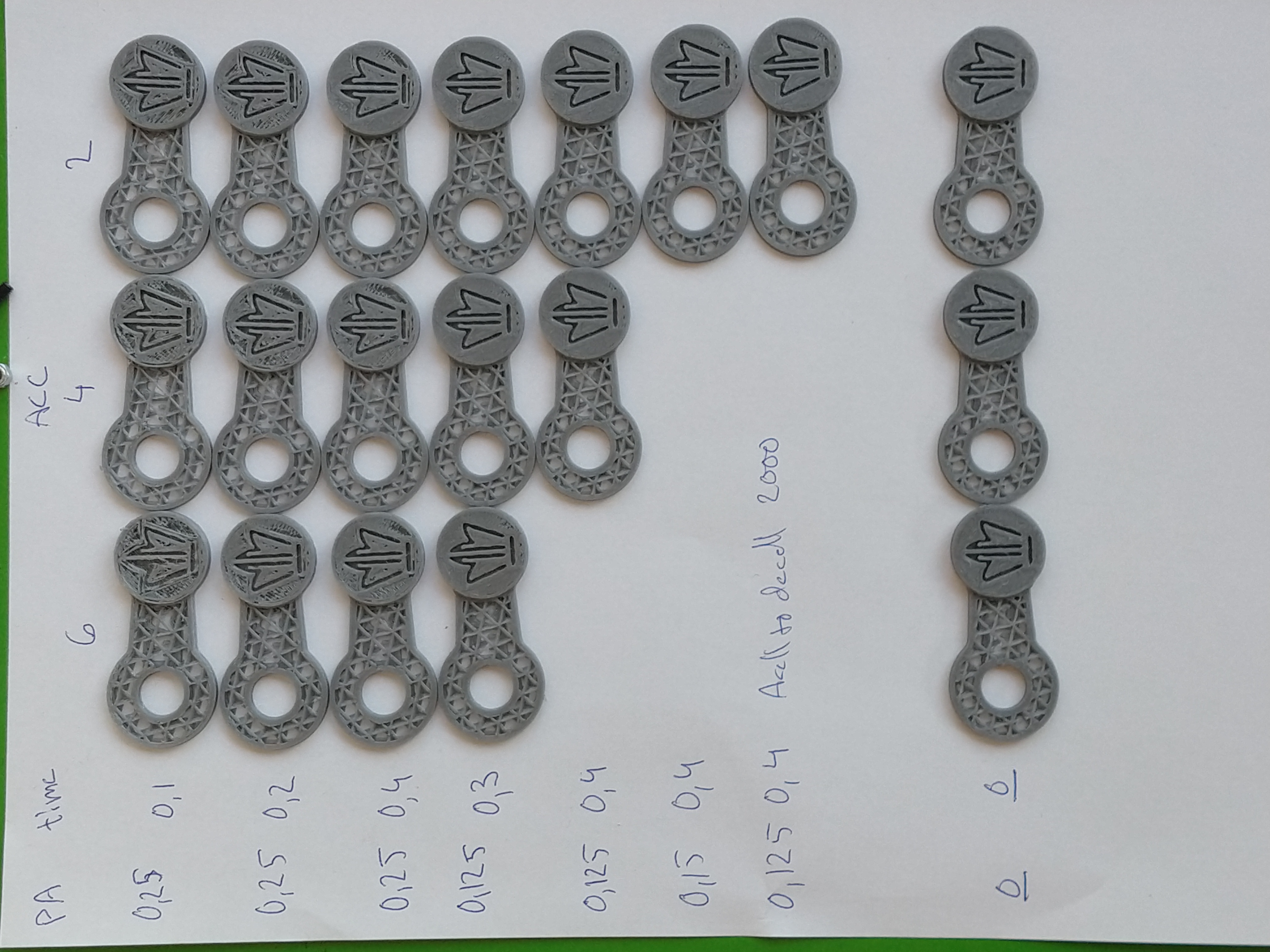
I couldn't see any improvements(slightly more ringing), and worse behavior regarding the skipped steps om my E.... And no benefits for pressure in the nozzle..
Hywelmartin
on 12 Aug 2019
@JohnEdwa the original S-Curve patch does not limit the kinematic jerk of the toolhead - so it should not slow the print down. Problem is, for sequences of short moves this creates jerky acceleration - the toolhead must start and stop the acceleration within the very short distance. Equivalently, this means a lot of short but powerful pushes, which may even make things worse compared to constant acceleration. This happens when printing pretty much any curved line, approximated by a large number of short lines.
I was playing with the S-Curve patch lately, and I've tried to mitigate this problem by limiting the kinematic jerk of the toolhead, which may limit the effective acceleration. Of course, that does slow the print down, but mostly short moves. Long moves are not affected and are performed with the full accelertion.
I mostly need S-Curve for the pressure advance - using high PA values and high acceleration for bowden extruder on delta printer makes the extruder rattle and skip steps sometimes, and probably reduces its life span. S-Curve w/o jerk control can make the situation even worse with PA on short moves. With jerk limit the whole thing works very smoothly, though a bit slower. I ended up using the following values:
max_accel - 2000-3000 (mm/s^2)
max_jerk - 30000 - 40000 (mm/s^3)
pressure_advance - 0.5-0.6
The patch should also be beneficial for users of direct extruders with high gear ratio, which can cope with the acceleration and speed jumps only so much.
If anybody wants to test it, please check out scurve-jerk-limit branch from here, branched from the current S-Curve branch. This may improve the ghosting on your printer even if S-Curve acceleration did not help before - but I cannot test this hypothesis unfortunately, because I don't see much of ghosting on my delta. The feedback is very welcome, especially which acceleration and jerk values you end up using, and pressure advance multipliers. To test, you should add
[printer]
max_jerk: ...
value to your config. Remember that this max_jerk is a real kinematic jerk in mm/s^3, not mm/s. I'd start with max_jerk ~= max_accel * 10 and try increasing it. There is no harm setting it too high though - it will simply work as the current S-Curve patch then, though you won't get the benefits either.
@KevinOConnor is this something that would be useful for the S-Curve patch integration? I am also working on the changes to the moves planning to combine the sequences of short moves into a single S-Curve acceleration, to mitigate the problem with the acceleration along the curved lines. But this kind of change requires a substantial rewrite of the MoveQueue class, extruder kinematic and related functions. Hence I'd want some feedback before doing that.
 dmbutyugin
on 16 Aug 2019
dmbutyugin
on 16 Aug 2019
@dmbutyugin - Interesting, thanks. It'd be interesting to see how limiting the maximum jerk impacts a traditional "bed slinger".
FYI, I have some high-level ideas on reworking the look-ahead code at https://github.com/KevinOConnor/klipper/issues/1758#issuecomment-522277236 . I'm not sure if that would help or conflict with the long-term changes you were thinking of.
-Kevin
KevinOConnor
on 20 Aug 2019
@KevinOConnor yes, it would be very interesting how it works with bed slingers and perhaps direct extruders. I wonder if anybody volunteers? What's the easieast way for people to test it? Perhaps switching to another repo is not very convenient. Should I create a pull request for my changes?
As for your other comment, I don't think my plans will conflict with that. If anything, perhaps my further changes can be made in the direction of preparation to your changes of iterative solver. My changes are focused around the python part of move planning. At high level, the changes required for itersolve are, basically, just passing the total acceleration time and the acceleration offset for each move in addition to what's currently being passed; this is sufficient to correctly compute the relevant part of Bezier curve for any given move. And then there is, of course, the extruder kinematics and pressure advance, which are more complicated :)
Implementing the windowed processing of moves in itersolve would be great indeed! Should help with many of the mentioned issues. Though I'm not 100% certain if it can help with the printer resonances: from my limited experience with the code, it seems like significant movement changes outside the normal move planning are tricky. For example, skipping 2 steps immediately one after another in TMC2208 issue should be easy then, but it is perhaps too late to limit the toolhead deceleration in itersolve - cause it may be required for the toolhead to come to a complete stop. Perhaps generating the steps outside the resonance frequencies?
Also, I'm not 100% sure what is the ultimate source of the printer vibrations, but I suspect that abrupt changes in the toolhead movement play some role in this - any step function has an infinite number of harmonics and can induce vibrations at pretty much any resonance frequency. And it just so happens that every corner must be accompanied with the abrupt changes - first the movement direction changes, then deceleration is immediately changes into acceleration, and so does the applied force. So it is very tricky to reduce the ghosting without reducing the square corner velocity, acceleration and jerk.
dmbutyugin
on 23 Aug 2019
@dmbutyugin
I have been wanting to test your scurve-jerk-limited on my bed slinger
Is it possible to bring your scurve-jerk-limited more in line with the current master?
I would be a happy volunteer then.
cheers
BlackStump
on 23 Aug 2019
@BlackStump done, I've synced my branch to the current KevinOConnor:master.
dmbutyugin
on 23 Aug 2019
I will hopefully get a chance tomorrow and give it a run
BlackStump
on 23 Aug 2019
Awesome, thanks!
dmbutyugin
on 23 Aug 2019
@dmbutyugin
Is there a Jerk crossover number where it has lost benefits and operates as the current S-curve patch?
BlackStump
on 24 Aug 2019
@BlackStump it is a bit more complicated than that. But as a general rule, the higher max_jerk (_J_) value is, the shorter are the moves that do full acceleration. For a simple case of acceleration from 0 speed, the relation is the following:
So, min max_jerk values required to do a full acceleration of 500 mm/sec^2 on a segment of
L=10 mm, 1 mm and 0.1 mm are
max_jerk = 15'000, 47'434 and 150'000 respectively (mm/sec^3).
Min max_jerk values required to do a full acceleration of 3000 mm/sec^2 on a segment of
L=10 mm, 1 mm and 0.1 mm are
max_jerk = 220'454, 697'137 and 2'204'540 respectively (mm/sec^3).
There's another consideration if one uses pressure advance: toolhead jerk directly translates into extruder acceleration: , where _P_ is the pressure advance parameter,
is the extrusion ratio, _D_ is the filament diameter, _d_ is the nozzle diameter, _h_ is the layer height. So, with _P_ = 0.5, _d_ = 0.4 mm, _h_ = 0.2 mm, _D_ = 1.75 mm, and _J_ = 100'000 the extruder acceleration is 1663 mm/sec^2 due to jerk.
So, I'd generally stick with max_jerk value of 100'000 - 300'000 max and wouldn't go over that.
dmbutyugin
on 24 Aug 2019
As a side note, even though the max_jerk patch limits the acceleration of short moves, short moves are never slower than the long ones :) For example, the time required to cover the move of length _L_, assuming it is limited by Jerk and that the initial speed is 0 is
It follows from here that if you want to reduce the time by 2x, you should increase max_jerk by 8x.
dmbutyugin
on 24 Aug 2019
Shouldn't that be extrusion width instead of nozzle diameter? Nozzle
diameter should not appear in the flow rate calculation as changing it
doesn't affect anything directly. It changes the pressure and that will
change the amount of advance needed.
On Sat, 24 Aug 2019 at 12:32, Dmitry Butyugin notifications@github.com
wrote:
As a side note, even though the max_jerk patch limits the acceleration of
short moves, short moves are never slower than the long ones :) For
example, the time required to cover the move of length L, assuming it
is limited by Jerk and that the initial speed is 0 isIt follows from here that if you want to reduce the time by 2x, you should
increase max_jerk by 8x.—
You are receiving this because you are subscribed to this thread.
Reply to this email directly, view it on GitHub
https://github.com/KevinOConnor/klipper/issues/57?email_source=notifications&email_token=AAEKHBNHDPCIMX7HNFM6LP3QGEL45A5CNFSM4EIJ4S32YY3PNVWWK3TUL52HS4DFVREXG43VMVBW63LNMVXHJKTDN5WW2ZLOORPWSZGOD5B6JJI#issuecomment-524543141,
or mute the thread
https://github.com/notifications/unsubscribe-auth/AAEKHBOPCUE3Q2LW37II5PLQGEL45ANCNFSM4EIJ4S3Q
.
 nophead
on 24 Aug 2019
nophead
on 24 Aug 2019
Yes, of course, that's more accurate. It's just easier and more generic for estimation purposes, since the extrusion width rarely differs a lot from the nozzle diameter.
dmbutyugin
on 24 Aug 2019
I guess I was trying to figure out how many test prints ie I have done a couple so far
first I did a test print that was 50mm high that every 10mm it changed accel, range went from 1000-3000. settled on 2000 that looked the best
I then did a test print that used 2000 as the accel but then ranged the jerk from 20000 to 60000
40000 seemed to look the best, but with out knowing a range I may have been in too narrow a field.
so from what you are saying maybe the first test 20000 to 200000
which is what I will try next.
but then should the tests be done with a high accel to focus on the jerk or more likely this is over my head hehe.
what would be the most logical way to do these test?
BlackStump
on 25 Aug 2019
I often print at 1.5 times the nozzle diameter, which is more than twice
the flow rate.
On Sat, 24 Aug 2019 at 17:29, Dmitry Butyugin notifications@github.com
wrote:
Yes, of course, that's more accurate. It's just easier and more generic
for estimation purposes, since the extrusion width rarely differs a lot
from the nozzle diameter.—
You are receiving this because you commented.
Reply to this email directly, view it on GitHub
https://github.com/KevinOConnor/klipper/issues/57?email_source=notifications&email_token=AAEKHBKAI3GHPCFE3VVOCF3QGFOVPA5CNFSM4EIJ4S32YY3PNVWWK3TUL52HS4DFVREXG43VMVBW63LNMVXHJKTDN5WW2ZLOORPWSZGOD5CDJ4A#issuecomment-524563696,
or mute the thread
https://github.com/notifications/unsubscribe-auth/AAEKHBL2V452WWZDMJTDZVTQGFOVPANCNFSM4EIJ4S3Q
.
nophead
on 25 Aug 2019
@nophead that's 1.5x the 'normal' flow rate AFAICT on sufficiently long extrude moves, because the total printed volume for a single line is _L_ _w_ _h_ + _π_ _w_^2 _h_ / 4. This mode of extrusion is usually not recommended, but as I said, you're right that _d_ = _w_ is the extrusion width really.
@BlackStump I'd say it sounds about right. You can also try 80'000 and 100'000 max_jerk for completeness. You can also try higher acceleration values, like 3000 or 4000, but that will affect mostly the long moves, short moves are typically limited by the max jerk, so unless your model is large with many straight lines, perhaps you shouldn't bother. Do you use pressure advance, BTW? And do you mind sharing some pictures of your results with different max_jerk settings?
dmbutyugin
on 25 Aug 2019
I made a model that seems to show the ringing on the Ender3 quite well.
There is a different jerk sweet spot for the X axis as compared to the Y axis, no surprise there.
I don,t think the ringing can be eliminated until the belt alignment design fault is fixed.
Accel_Jerk_ test model .zip
I have include the test model.
I change the jerk starting at 20000 by 20000 every 5mm with accel of 2000
X axis
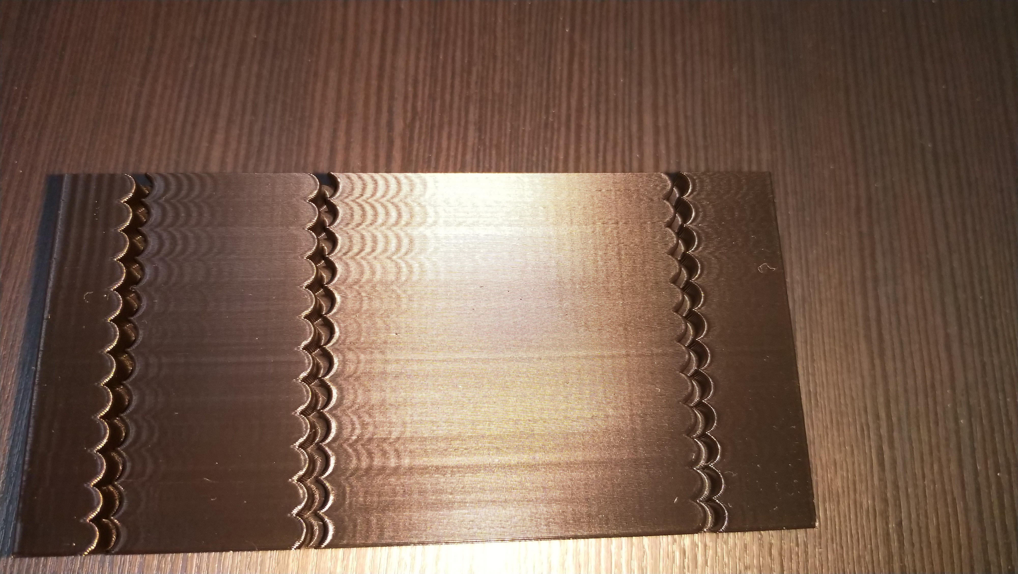
Y axis
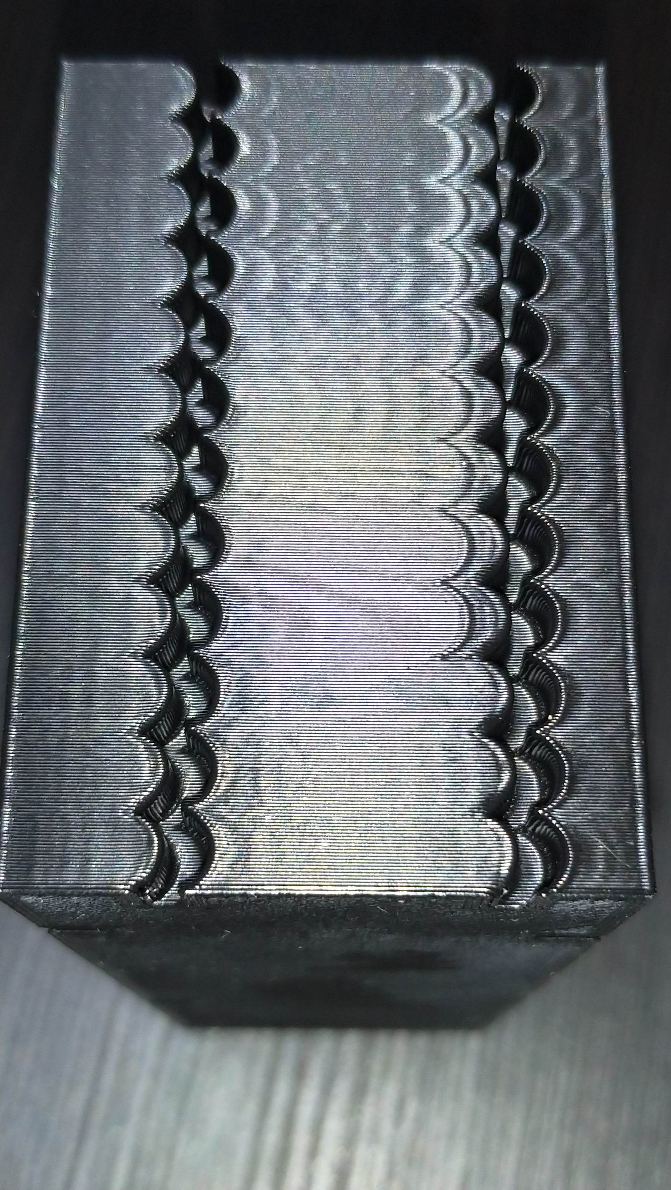
pic of the model
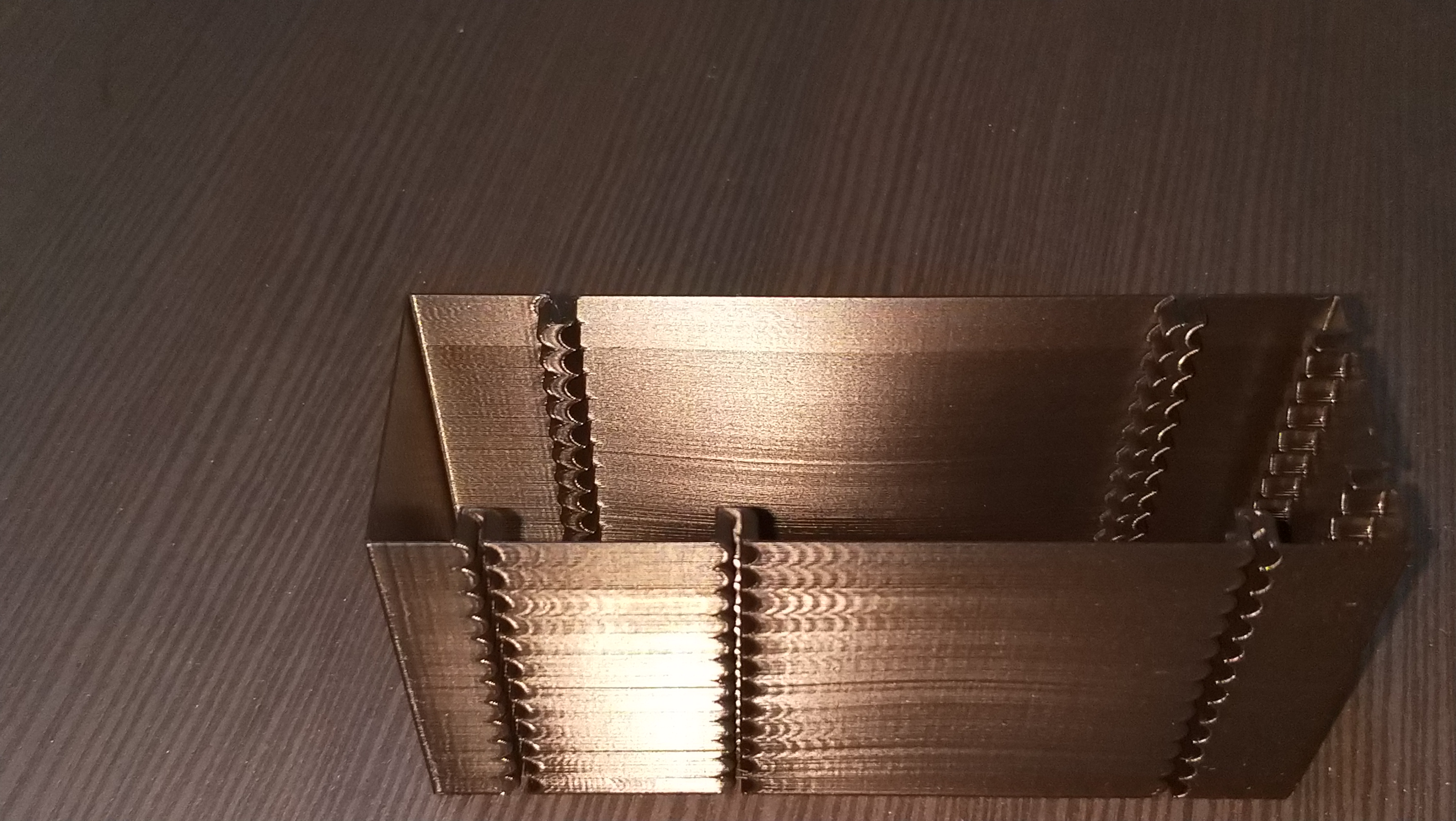
I do use PA of 0.25 which was left unchanged, I will do a test to see if that PA has changed.
It seems to me the Y axis limit is jerk 60000, X axis seems to look best at 100000-140000
a quick and dirty pic of the ender3 belt alignment problem, what it is and what it should be imho
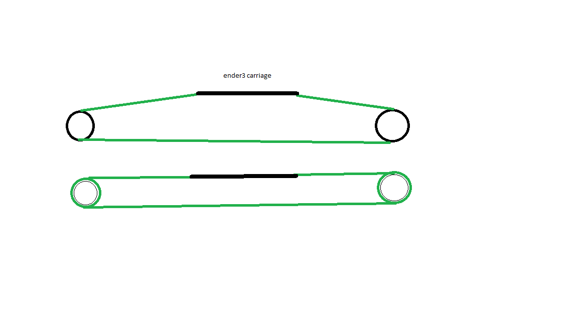
BlackStump
on 25 Aug 2019
@BlackStump regarting the belt alignment issue there are some solutions....
I myself did mod something for multiple purposes like this:
https://www.thingiverse.com/thing:3780434
But there are others like these ones:
https://www.thingiverse.com/thing:3668847
https://www.thingiverse.com/thing:3288949
All of then require this one https://www.thingiverse.com/thing:3537042
Good luck ;)
 danielfmo
on 25 Aug 2019
danielfmo
on 25 Aug 2019
@danielfmo
Thanks for the links it has been on the radar for awhile to fix.
BlackStump
on 25 Aug 2019
@BlackStump interesting, thanks! You are using acceleration_order = 4, I assume? Anyways, there's a clear evidence that max_jerk has quite some impact on the quality of the print. Could you also print this model with acceleration_order = 2 (normal Klipper operation) and the original s-curve patch for completeness of the comparison? Of course, no need to print the full model, just enough to show the quality.
I also wonder why there's clear ghosting even at low jerk values. What square_corner_velocity are you using? Could it be that it's too high for the printer? I.e. could you also additionally try lowering it with a couple of max_jerk values, e.g. 60000 and 20000? It's also interesting that starting with 80000 jerk there's ghosting on Y axis even _before_ one of the notches, with the constant offset from it, which is really strange. Is there any play on either of the axis, besides the misalignment of Y axis belt?
dmbutyugin
on 26 Aug 2019
@dmbutyugin
there is some weirdness on Y as you pointed out but I also noticed there is holes in the print on the backside of the X axis after the last little section which leave me to think it is a PA setting.
I tried late last night to do a PA test but the first gcode change to PA shut the printer down.
divide by zero error (sorry did not copy the error)
Anyways I was using acceleration_order=6 and yesterday I improved the belt alignment on X and Y so I will start the testing again. I need to figure out why I cant do the PA test.
More pics and info to come next couple days
BlackStump
on 27 Aug 2019
@BlackStump thanks! Please post klippy.log(s) for any failures you encounter and/or stack traces from it, this will help find and fix any remaining issues. Also just in case please pull all the changes from the branch, though I think I did some small fixes before syncing to the head of KevinOConnor:master, so you should already have all fixes.
dmbutyugin
on 27 Aug 2019
I changed the model to duplicate the same model pattern X and Y axis.
I started off at accel 1000 and jerk 100000 and added 20000 every 5mm to max of 160000 then changed accel to 2000 repeat then changed to accel 3000 repeat.
print speed 80mm/s
results are much harder to pick up on my phone camera.
X axis
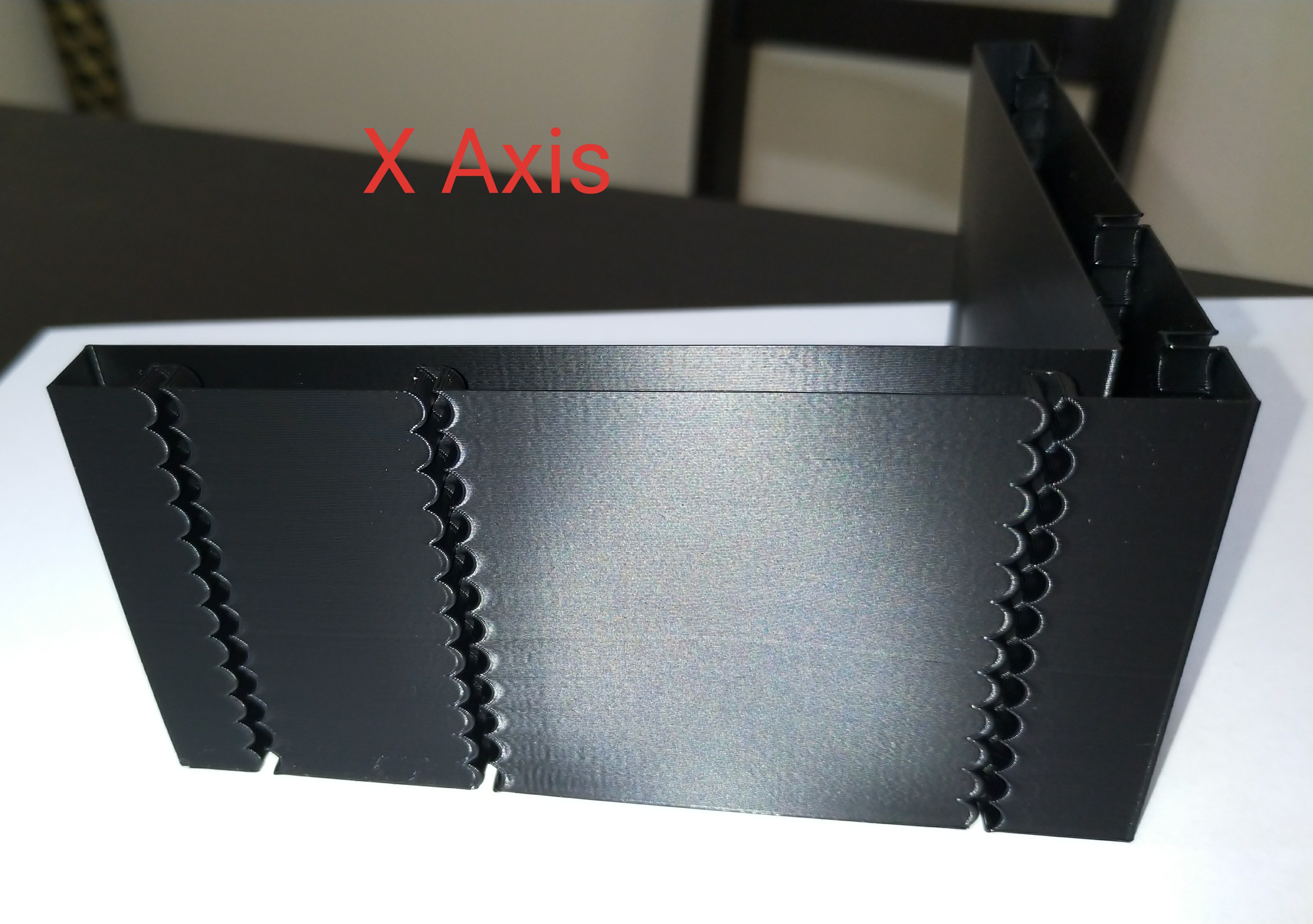
Y axis
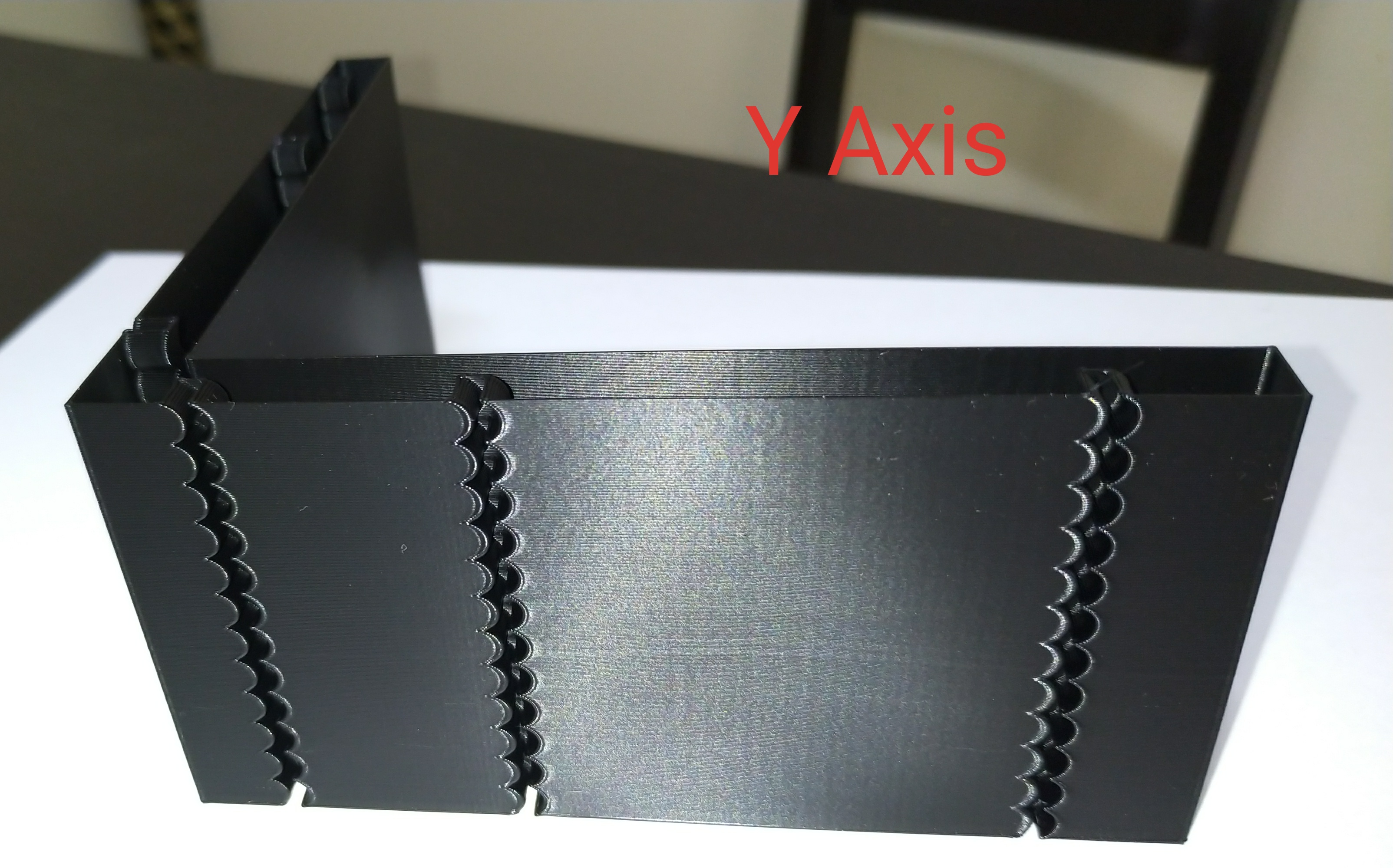
model
Accel test model v2.zip
gcode used on the ender3 of the above model
Accel test model v2.zip
I reduced square_corner_velocity from 7 to 2
I reduced PA from 0.25 to 0.14
test was with acceleration_order = 4
A major improvement I think but more testing to come
BlackStump
on 27 Aug 2019
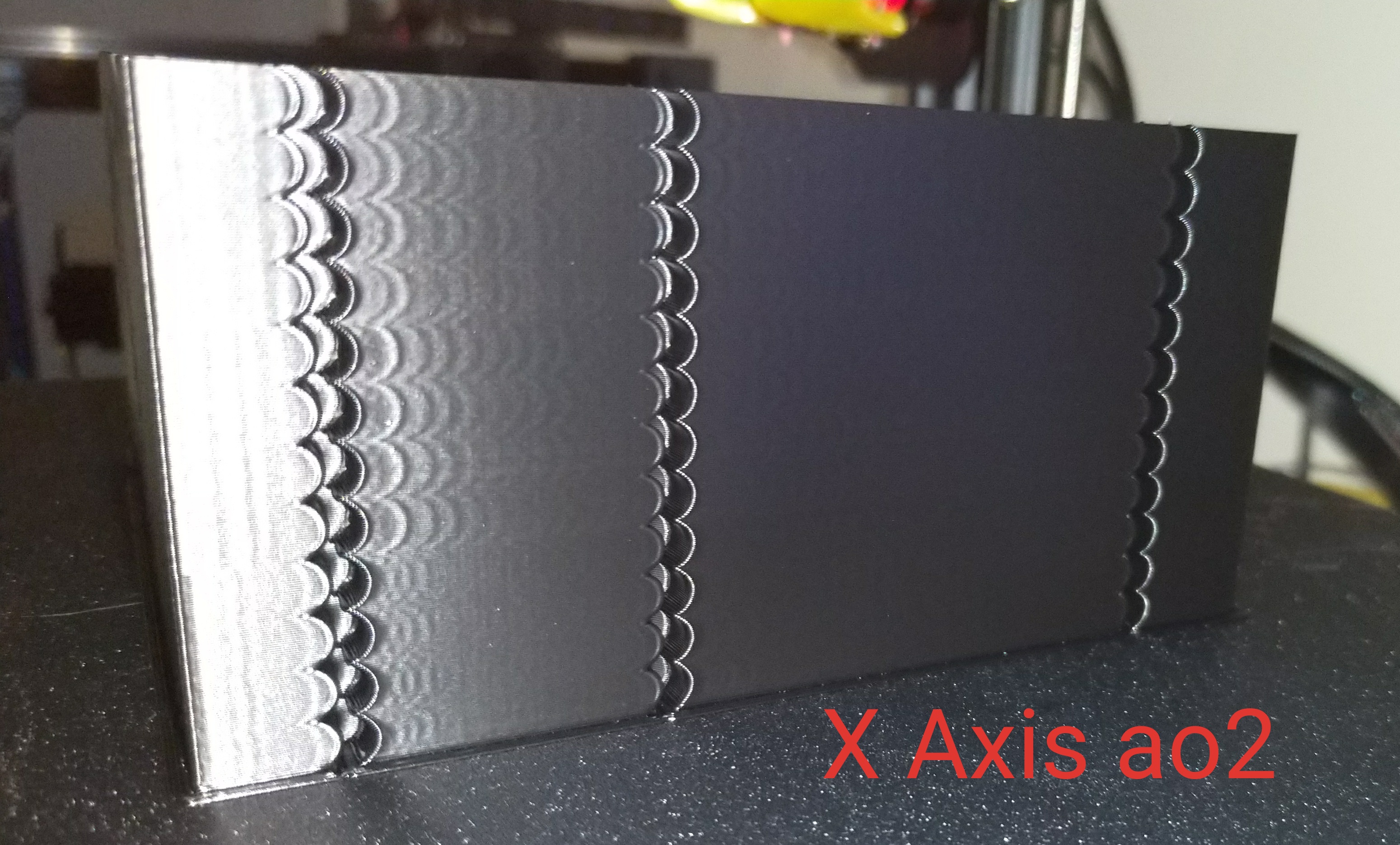
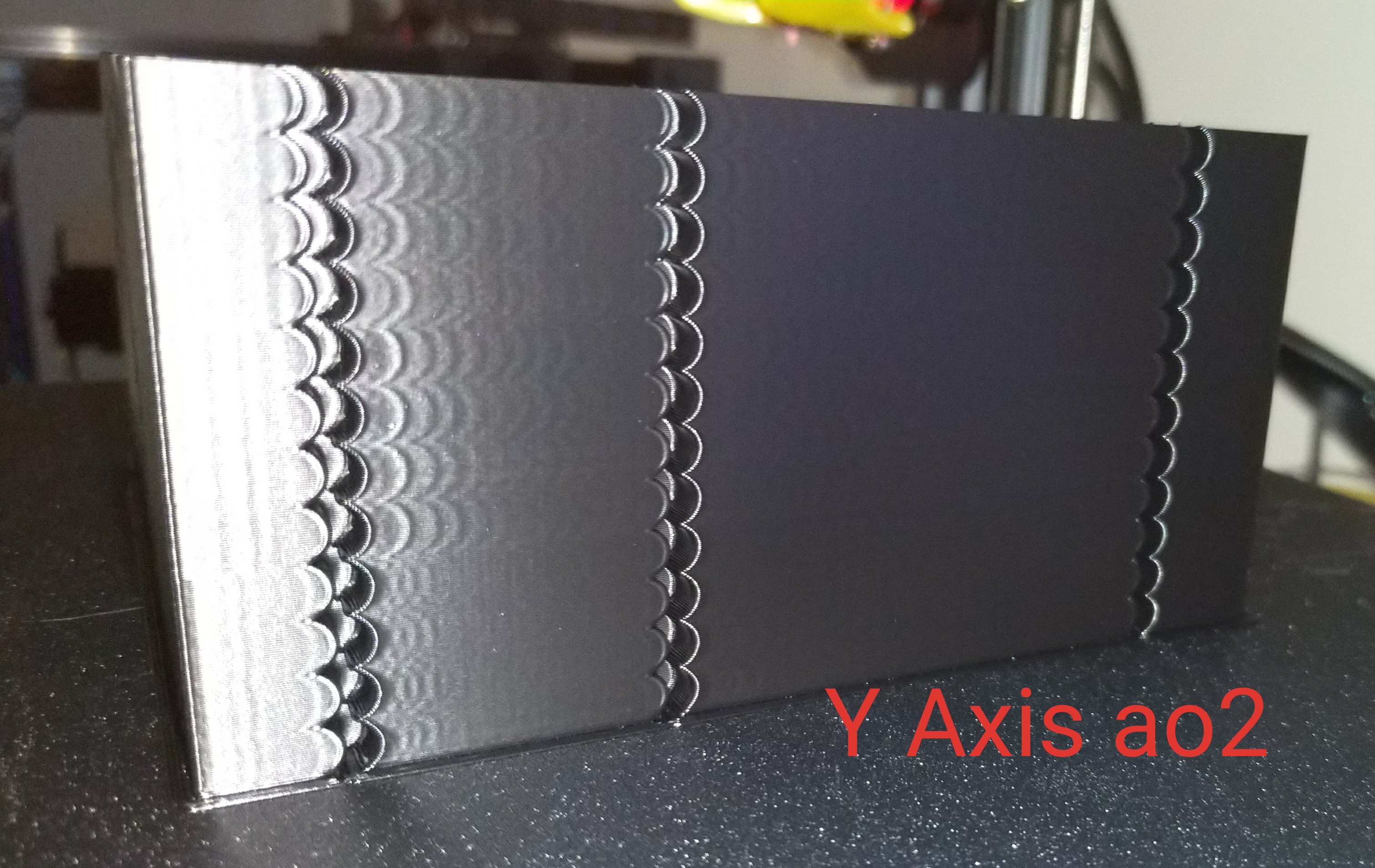
same details as before only acceleration_order=2
BlackStump
on 27 Aug 2019
the 3 together
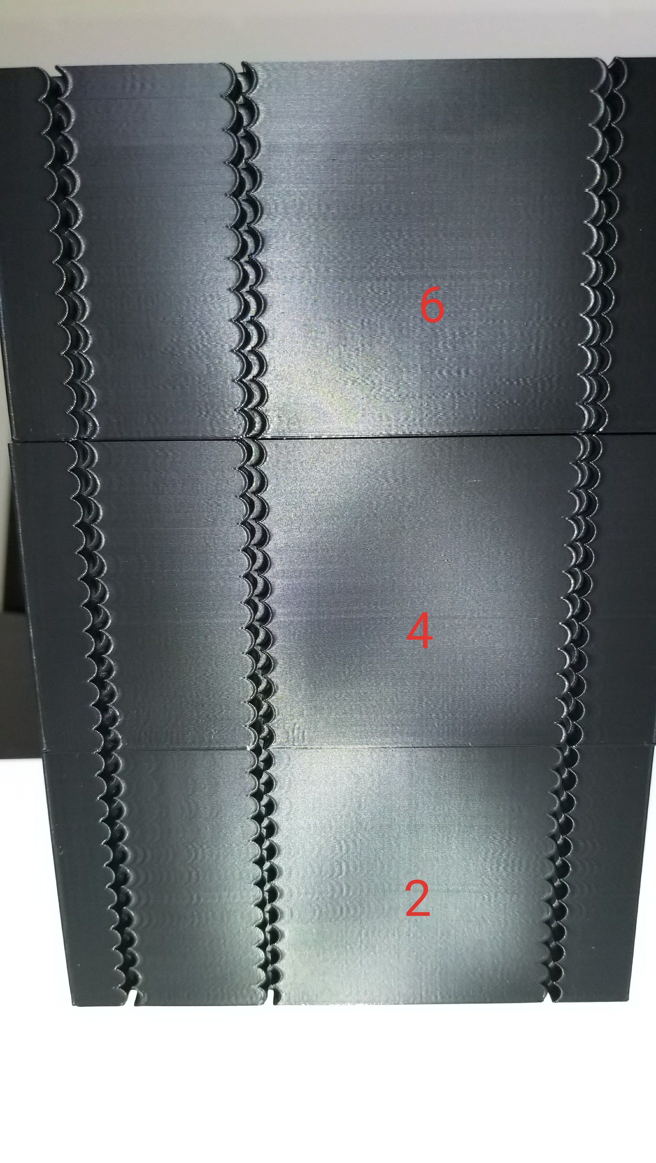
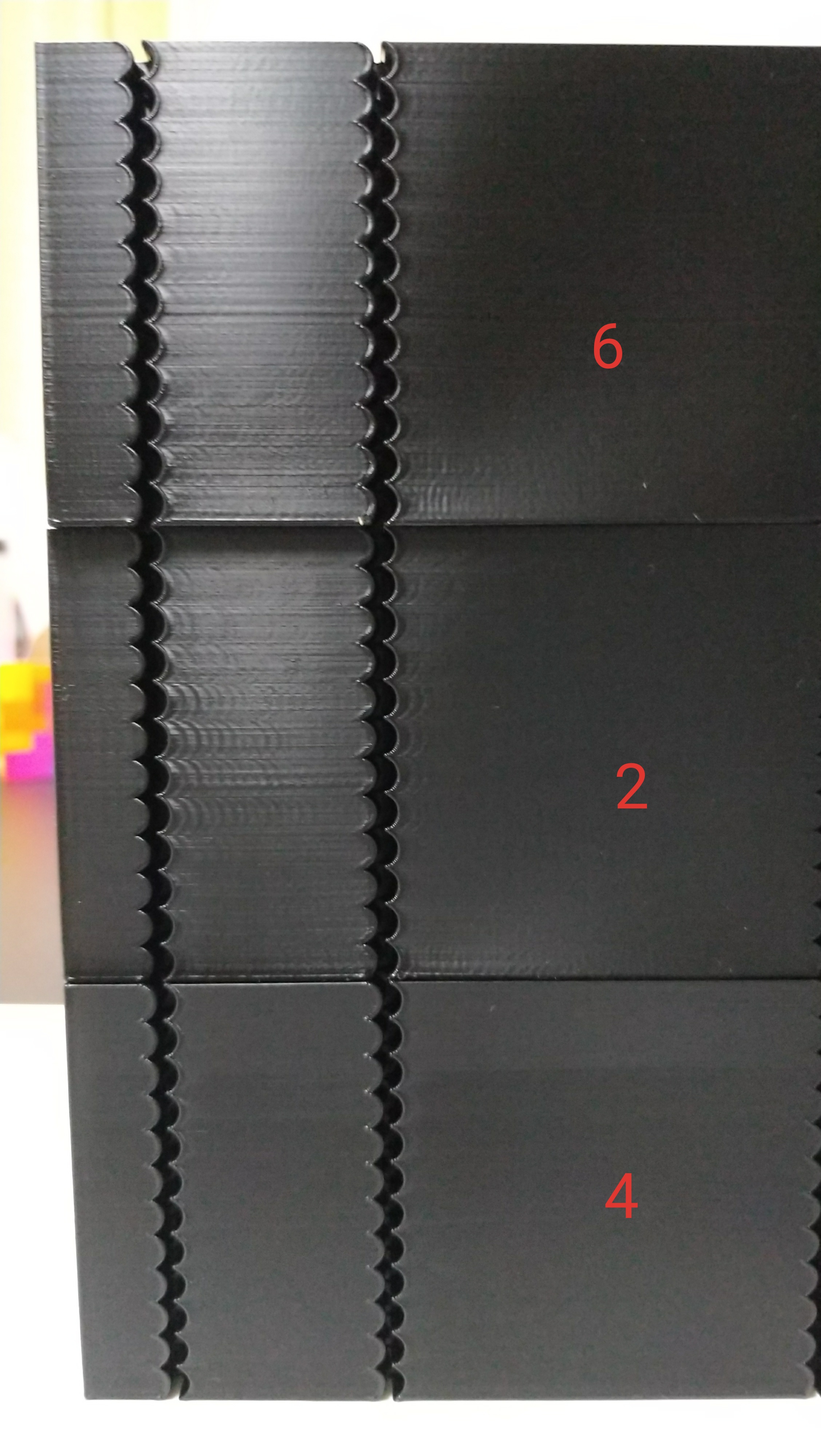
BlackStump
on 27 Aug 2019
@BlackStump In your previous comment, acceleration_order=2, what are the differences between layers? Did you increase the acceleration? max_jerk value has no effect with acceleration_order=2.
Otherwise, you've got really nice improvements of the quality now! What did you do exactly? Is it just the reduction of the square corner velocity? Or did you also fix the belt alignment? What was the most contributing factor? BTW, right now there seems to be no significant differences with ao=4 and 6 with different max_jerk values.
dmbutyugin
on 28 Aug 2019
@dmbutyugin
The tests used the same gcode and same parameters only the acceleration_order changed
I started off at accel 1000 and jerk 100000 and added 20000 every 5mm to max of 160000 then changed accel to 2000 repeat then changed to accel 3000 repeat.
print speed 80mm/s
I reduced square_corner_velocity from 7 to 2
I reduced PA from 0.25 to 0.14
I agree there is only very subtle differences between ao=4 and 6 at the moment either will produce better results then ao=2
In the tests that I have done it is pretty conclusive that scurve-jerk-limited is a big improvement.
I been test printing for 2 days but really a test with the same parameters using the original scurve patch should be done for completeness.
always a bad idea to change too many things at once so I cant say for sure what contributed to major improvement specifically. I suspect it was the combination of the above.
I need to do the same test with square_corner_velocity=7
I always thought ringing is not a factor of firmware settings alone, hardware in this case belt alignments but also other hardware factors contribute to ringing.
It would be great if some other people could use the model and or gcode to run tests.
there are so many different combinations of parameters to try and test I could test for a further week.
BlackStump
on 29 Aug 2019
@BlackStump I see, so ao=2 only differed by acceleration, and there are 3 big layers there visible on the photo. Makes sense. Yes, it would be great to test the original s-curve patch for completeness to see what quality we get w/o limiting the jerk. Although from your tests we can already see that limiting the jerk does impact the quality quite a bit. Also, it is hard for me to judge from the photos, but it seems there are no noticeable diffs in quality between different accelerations and the same max_jerk values with ao>2, is that correct? So that with ao>2 max_jerk plays more important role for the quality than max acceleration?
If that's right, I think we can suggest the following tuning technique:
- Choose max acceleration suitable for your printer (e.g. such that motors don't skip steps, there is not much printer wobbling, etc.).
- Set ao>2 and low max_jerk value (e.g. 10'000-20'000).
- Print a test model (like you've created) increasing square_corner_velocity from 0 by a small amount every X layers/mm. E.g. increase square_corner_velocity by 1 mm/s every 1-2 mm in Z.
- Set square_corner_velocity to max value such that the quality is still good.
- Print the same test model now increasing max_jerk value, say, by 5000-10000 every X mm.
- Set max_jerk to max value such that the quality is still good.
- Tune PA and consider lowering max_jerk if necessary to avoid extruder skipping steps or increasing the stepper current as appropriate.
I'm not sure how to choose between ao=4 and ao=6, perhaps doing 5 with both and just choosing what works best (higher max_jerk value). I suppose for many cases ao=4 is sufficient.
dmbutyugin
on 29 Aug 2019
It was hard to get the camera to pick up the details but with
ao=2 accel =1000 was the best
ao=2 accel=2000 was the worst overall
ao=2 accel=3000 was better on the longer sections worse on the shorter sections if that makes sense
It would seem accel seems to be less important when using ao>2 then finding the jerk sweet spot.
What you suggested as a tuning technique is right or at least a good start.
Looking under sunlight and rotating the model to pick up any artifacts, I would suggest ao=6 is best but is is subtle, there is still ringing there but very faint in either 4 or 6 just slightly less pronounce on 6
BlackStump
on 29 Aug 2019
Some update: though I have not seen division-by-zero myself, I think I have eliminated that possibility now.
@KevinOConnor I've also put together an initial version of documentation for S-Curve acceleration. Can you take a look at it and share your opinion? If it's too wordy, I can delete some unrelated stuff from there. Sorry for possible typos, I'll do a few rounds of proofreading, but please let me know if you find some. What else is needed for the initial S-Curve implementation?
@BlackStump Would you be fine if we used your test model (v2) in S-Curve tuning recommendations? I think it's pretty good because it can surface the typical problems with ringing. Did you put it together by yourself?
dmbutyugin
on 4 Sep 2019
@dmbutyugin I was curious about S-curve acceleration and Jerk - limited acceleration, so I checked out your branch to have a play.
From doing some basic testing (just typing gcode into the octoprint terminal) I noticed the movement looks a little strange, it seems the movement is asymetrical. What I am seeing is that jerk only appears to be applied to deceleration (end of the move) when travelling in a positive direction (x0 -> x100) and only applied to acceleration (start of the move) when traveling in a negative direction (x100 -> x0)
This is easy to spot if you set a really low jerk value and set the print head moving back and forth, movements near the origin do have acceleration, but it doesn't appear to be affected by the jerk value, whereas movement near the other end of the axis appears to have jerk applied.
ao=2 works as expected
ao=4 and ao=6 both show the asymmetric acceleration
 AshIzat
on 4 Sep 2019
AshIzat
on 4 Sep 2019
@AshIzat thanks for trying! This is very bizarre.. I just tested it myself on my printer, and I do not get this behaviour. Could you try the following: ssh to your pi, or whatever you're using for Klipper, and then run
$ sudo service klipper stop
$ rm klipper/klippy/chelper/c_helper.so
$ sudo service klipper start
and try again? If the timestamps of the files got mixed up, perhaps Klipper did not realize it should rebuild the library, but the ABI changed. I did have an issue with this before, but I don't remember what the problem was.
And if this does not help, can you attach klippy.log from your test run?
dmbutyugin
on 4 Sep 2019
@AshIzat and another related thing: did you switch to the scurve-jerk-limit branch in-place of existing installation? Maybe it would make sense to also try deleting precompiled python files to be on the safe side? Like, when Klipper service is stopped, also run
$ rm klipper//.pyc klipper///*.pyc
and only then start it again.
dmbutyugin
on 4 Sep 2019
*Ah, the command got mess up, I forgot to escape it.
$ rm klipper/*/*.pyc klipper/*/*/*.pyc
dmbutyugin
on 4 Sep 2019
I've run the above commands and I'm still getting the same behaviour.
[printer]
kinematics: cartesian
max_velocity: 500
max_accel: 2000
max_z_velocity: 20
max_z_accel: 100
square_corner_velocity: 3
acceleration_order: 6
max_jerk: 1000
Gcode I'm running
g90
g1 x10 z20 y10 f12000
g1 x180 z20 y180 f12000
g1 x10 z20 y10 f12000
g1 x180 z20 y180 f12000
g1 x10 z20 y10 f12000
g1 x180 z20 y180 f12000
g1 x10 z20 y10 f12000
g1 x180 z20 y180 f12000
g1 x10 z20 y10 f12000
@AshIzat OK, just to be sure: are you running the latest version of the code from scurve-jerk-limit branch? Can you pull the changes and restart klipper just to be sure?
Also, please attach /tmp/klippy.log file from after your test, it should help debugging this problem a lot. Thanks!
dmbutyugin
on 5 Sep 2019
pi@octopi:~/klipper $ git status
On branch scurve-jerk-limit
Your branch is up-to-date with 'scurve/scurve-jerk-limit'.
nothing to commit, working tree clean
pi@octopi:~/klipper $ git log -n1
commit 463d50bbfcdebd8609302b13554a63d8ce288ff3
Author: Dmitry Butyugin <[email protected]>
Date:   Wed Sep 4 21:08:53 2019 +0200

    Some documentation fixes
@AshIzat very interesting. Can you please also try to disable [bed_mesh] in your config and test without it? I'd think it should be safe as long as you do it a bit off the printbed, e.g. with Z=10-20mm. Bed meshing subsplits the moves, and I'm worried that it may interfere, because the acceleration is limited more on short moves by design. And I am still yet to implement combining several moves into a single acceleration.
dmbutyugin
on 5 Sep 2019
@dmbutyugin
I made that model in fusion 360 from scratch but the idea came from the square model which came from a single layer model from thingiverse from memory, I can not find that model again on thingiverse, it was downloaded a couple years ago.
can you use that model I made sure, not sure how to acknowledge the original idea of a circular notch or even if that is necessary as the only similarities is the idea of the circular notch.
btw when I had the divide by zero issue I disabled bed_mesh and skew which solved that issue and had them disabled for all tests, I have not actually re enabled and verified that they were in fact the cause. Or done any testing with bed_mesh and skew enabled.
BlackStump
on 5 Sep 2019
@dmbutyugin removing bed_mesh fixed the issue
klippy.log
AshIzat
on 5 Sep 2019
@AshIzat All right, it's quite unfortunate actually. It's the interaction between the two features: S-Curve acceleration and bed meshing. I updated the docs to reflect this. Basically, S-Curve acceleration slows down short moves. Incidentally, bed meshing segments long moves into short ones to account for the bed surface height changes. This can lead to inconsistent acceleration across the print area depending on segmentation density. If you must use bed meshing, you can set fade_start < fade_end options in [bed_meshing] section to small values (i.e. a few millimetres) to stop Z-height adjustments early and set max_jerk to a reasonably high value (around 40000-50000 or more) to make sure the print is not too slow during these initial few millimetres.
Ultimately, this is not so easy to fix. As I mentioned, I am also working on the changes to the moves planning to combine the sequences of short moves into a single S-Curve acceleration, to mitigate the problem with the acceleration along the curved lines. It should also help with bed meshing. But this kind of change requires a substantial rewrite, so it'll take some time unfortunately.
dmbutyugin
on 5 Sep 2019
@BlackStump I would prefer to use your model. But ultimately it'll be @KevinOConnor call if he accepts it or not. If or, hopefully, when we decide to integrate this patch into the mainline, maybe you can make a separate pull request specifically with your model, which can be referenced then in the documentation.
dmbutyugin
on 5 Sep 2019
@dmbutyugin It's okay, I wasn't planning on using S-curve just yet, I just wanted to try it out and noticed it was acting weird so thought I should report my findings. Cheers. :)
AshIzat
on 5 Sep 2019
Yes, thank you for reporting! Now we know that the bed meshing poorly interacts with jerk limit. But at least it was not some nasty bug :) You can still give it a try at some point, just enabling the fadeout.
dmbutyugin
on 6 Sep 2019
Surely bed mesh correction only creates very gently curves compared to the
curves that are normally part of the model. Why does it cause a problem? I
would have thought that the corrections would be so small that no
deceleration / acceleration is needed.
On Thu, 5 Sep 2019 at 22:15, Ashley Izat notifications@github.com wrote:
@dmbutyugin https://github.com/dmbutyugin It's okay, I wasn't planning
on using S-curve just yet, I just wanted to try it out and noticed it was
acting weird so thought I should report my findings. Cheers. :)—
You are receiving this because you were mentioned.
Reply to this email directly, view it on GitHub
https://github.com/KevinOConnor/klipper/issues/57?email_source=notifications&email_token=AAEKHBJKC52IVT5TUWRUKM3QIFZGHA5CNFSM4EIJ4S32YY3PNVWWK3TUL52HS4DFVREXG43VMVBW63LNMVXHJKTDN5WW2ZLOORPWSZGOD6AZSZI#issuecomment-528587109,
or mute the thread
https://github.com/notifications/unsubscribe-auth/AAEKHBMAVQVFGONML7OYRKDQIFZGHANCNFSM4EIJ4S3Q
.
nophead
on 6 Sep 2019
What Ashlzat reported was that the acceleration at the beginning and the end of the move was different. This is because of the move segmentation. But you are right @nophead that normally acceleration/deceleration is not needed during long moves. Still, they will be slower overall due to this end effect. And if you have a model that requires lots of direction changes when being printed, the effect amplifies. But I'd agree it's probably not that bad, just looks surprising, like a bug.
dmbutyugin
on 6 Sep 2019
Is it perhaps that with bed levelling you have Z motion, whereas without all the moves are just XY?
nophead
on 6 Sep 2019
ao=2 accel =1000 was the best
ao=2 accel=2000 was the worst overall
ao=2 accel=3000 was better on the longer sections worse on the shorter sections if that makes sense
FYI, dc42 did a lot of testing (on RepRapFirmware) and he came to the conclusion that the total time of acceleration had a larger impact on ringing than the magnitude of acceleration, the amount of instantaneous velocity change, and the shape of the acceleration curve. There's some details at: https://forum.duet3d.com/topic/5951/periodicity-of-ringing/39 . My summary - the total move acceleration time may either excite or cancel resonance in the printer's belts/frame.
Be aware that max_accel, move velocity, square_corner_velocity, and this new jerk parameter all impact the total acceleration (and deceleration) time. This makes it particular difficult to tune these parameters by observing ringing, because an increase in a parameter may actually reduce ringing when in reality it may need to be decreased. That is, an increase in a parameter may change the total acceleration time so that the movement no longer excites resonance, but a general performance improvement may require the given parameter to be decreased (and some other setting tweaked to avoid the resonance).
-Kevin
KevinOConnor
on 6 Sep 2019
@dmbutyugin
I put the model up on thingiverse
https://www.thingiverse.com/thing:3847206
BlackStump
on 9 Sep 2019
@BlackStump Thank you! I will put a link to your model into the documentation.
For the other question: no, it has nothing to do with Z changes. Just with the fact that the move was split unevenly into small segments at its different ends. The more smaller segments - the lower is the acceleration with the current implementation without combining the moves.
dmbutyugin
on 10 Sep 2019
Doesn't motion planing always need to look ahead and backwards to the points where the speed is zero in order to know the max speed and where to start accelerating and decelerating? The short segments should only have a significant effect if they have significant changes in direction.
nophead
on 10 Sep 2019
@nophead it has nothing to do with look-ahead queue currently. When limiting the jerk, the code computes the maximum attainable speed given the initial velocity, segment length and max_jerk value. For very short segments, max_v^2 - start_v^2 << 2 * L * a, so then if you sum up many small segments, you don't get the same maximum velocity as you'd get if it was a single segment. This is a limitation of the current implementation.
@KevinOConnor thank you for the link! It is very interesting study. I'm afraid that the real printer may have different resonances, so cancelling them all by timing the acceleration is not easy, if at all possible.
I decided to try some simulations in Python to see how different acceleration orders would perform. I started with a simple harmonic oscillator. I computed its oscillations depending on how many periods the accelerating force acts on it (with ao=2, 4, and 6). Here are the results, and I find them very interesting:
It confirms dc42 finding that proper timing can cancel the resonances with constant acceleration. A few caveats are:
- acceleration timing must be pretty precise, otherwise there's not much of the desired effect, and it's hard to measure the ringing frequency precisely; it's also going to be very difficult to select acceleration timing if there are multiple resonances
- if acceleration spans several periods of oscillations, the oscillations still occur during that time.
- it is possible to get better results with higher max acceleration than with lower in the test environment because of the better timing against ringing frequencies, but it will be a poor choice overall, as Kevin mentioned.
Now to higher order acceleration:
- if acceleration time is greater than around 2 periods, the oscillations are almost completely cancelled regardless of the exact acceleration time. ao=6 performs better in this case than ao=4.
- if acceleration time is close to the oscillation period, the oscillations can be even greater than with ao=2. I think this is what happened to some people who observed increased ringing with higher order acceleration.
Then I simulated harmonic oscillator with damping. I must admit that I just chose the damping parameter such that it shows some noticeable damping after several oscillations. How much it corresponds to the real systems is up to debate, but at least people typically observe that ringing stops after a few periods, maybe 10-20 max. The results of the simulation are as follows:
I think this is even more interesting. It shows that if acceleration spans several oscillation periods, it becomes impossible to cancel the vibrations in ao=2 case even if the acceleration is perfectly timed to an adjusted resonance frequency. This happens because the oscillator does not get to the same state after each period due to losses, so when the force is relieved, new oscillations start again. And with ao > 2 vibrations seem to be even smaller with damping than without it.
So in short, ao > 2 performs well if T_a << T_r or if T_a > X * T_r with X~=2-3, where T_r is the period of ringing and T_a is the acceleration time. ao=2 performs well if T_a << T_r or if T_a = K * T_r with K being an integer, and in real life the performance deteriorates as K increases. Still, if T_a ~= T_r ao > 2 usually shows stronger ringing than ao = 2. This is all without accounting for or limiting the kinematic jerk.
Now, the amplitude of ringing is proportional to the applied force, which is proportional to the acceleration. Another way to reduce the ringing is to reduce the acceleration. Incidentally, when we limit the kinematic jerk, we in fact limit the following value: a / T_a <= max_jerk / 6, where a is the average acceleration of the S-Curve. Then, if we choose
max_jerk = 6 * a / T_r * 0.1
we will reduce the amplitude of oscillations when T_a ~= T_r by a factor of 10x! And if we calculate this number for some typical cases, it's actually pretty sane. For example, if a = 3000 mm/sec^2, T_r = 0.01 sec (ringing frequency is 100 Hz), then max_jerk = 180'000 mm/sec^3.
I went ahead and simulated oscillations of the printer doing acceleration from 0 to different velocities in (0, V] with different ao values. Let's first consider a = 3000 mm/sec, ringing frequency 100Hz, max_jerk = 180'000 mm/sec^3 and V = 200 mm/sec. Here are the results:
The black line shows the point in time where the acceleration ao=2 is finished, the purple line - where the acceleration ao=4,6 is finished. It's easy to see that limiting max jerk this way reduces the amplitude of vibrations very well for all speeds the printer accelerates to, even when T_a ~= T_r, at the expense of somewhat slower acceleration.
Then I simulated a different set of parameters which may, perhaps, represent a poor-quality printer: a = 1000 mm/sec, ringing frequency = 20 Hz (low frequency ringing) and V = 100 mm/sec. I used max_jerk = 24'000 mm/sec^3 which reduces the ringing only by 5x instead of 10x, but I thought that max_jerk = 12'000 is just too low for the practical use. The results are still not bad at all and show significantly less ringing with S-Curve acceleration than ao=2:
This study shows that if S-Curve acceleration with jerk limit is used, then:
- maximum acceleration does not play a major role (usually the moves are limited by jerk) and can be left alone; no tuning is really necessary
- there is a good default choice for max_jerk parameter if one determines the lowest ringing frequency: max_jerk = 0.6 * max_accel * ringing_freq, but can be decreased or increased a bit to get better results or faster prints
- ringing_freq can be determined from the test print, better with ao = 2 by setting sufficiently high max_accel and changing it or a print velocity a bit to get better view of ringing
- there is another parameter that has large impact on ringing: square_corner_velocity, which wasn't covered above, but it's still very important. It is better to do ringing_freq and max_jerk tuning with a low square_corner_velocity value (e.g. 1.0), then separately tune it before ringing starts to appear.
For my own delta printer, I have measured the ringing with V=100 mm/sec. I got 6 periods of oscillations over 11.5mm, which gives ringing_freq = 100 * 6 / 11.5 = 52 Hz. I typically use max_accel = 3000 mm/sec^2 with ao=2, this gives the suggested max_jerk = 93'600. When printing the test model increasing max_jerk from 20'000 to 120'000 I did not observe any ringing. I ended up using max_jerk = 70'000 because of high pressure_advance=0.6 value I use.
I'm even thinking if it is a good idea to add two parameters to the configuration, asking the user to provide one of the two: max_jerk and ringing_freq. ringing_freq is easier to measure and there is no need to further tune it. Then if only ringing_freq parameter is provided, max_jerk can be computed from it. But if the user wants to specify max_jerk explicitly (e.g. for pressure advance), they can still do it. We can even have some sort of default value for ringing_freq around 40-60Hz (citation needed) that'll be not too bad for most of the printers :D
dmbutyugin
on 10 Sep 2019
Good stuff Dmitry, thanks for doing the legwork and the writeup.
Nophead mentioned multiple resonances, but I think it’s worse than that. Many types of printers have meaningfully different resonant frequencies at different nozzle positions. The i3 arrangement is pretty much best-case: you have a heavy Y bed that is more or less position-insensitive, and an x bridge that only mildly depends on Z height. But a CoreXY gantry moving in two dimensions will have X resonant frequency as a function of Y position, and vice versa. A delta’s resonances are just all sorts of screwed up.
If you tune parameters for antiresonance at nozzle at bed center, you might end up with additive resonance in other parts of the build plate. It’s just a very complex mechanical system.
You could use an accelerometer to dynamically auto tune a vibration scan across the build plate, but short of that, I’m worried that features like this will only benefit a small number of usage cases and end up being a wild goose chase for other users.
Don’t want to discourage the work at all though, this is the sort of conversation and research that we need to be having to improve performance. Just giving my two cents.
rcarlyle
on 11 Sep 2019
Thanks for providing the detailed analysis.
It is very interesting study. I'm afraid that the real printer may have different resonances, so cancelling them all by timing the acceleration is not easy, if at all possible.
I agree. I'm also not convinced that the solution dc42 was pursuing will be practical. I did wish to point out that the phenomenon can make tuning quite tricky. To wit, if one is not careful they may end up tuning parameters that "cancel resonance in the test print", instead of "reducing resonance in general prints".
I'm still studying the details of your post. One question - what are the X axis units and Y axis units on the graphs?
-Kevin
KevinOConnor
on 11 Sep 2019
@KevinOConnor X axis on the first two charts is dimensionless time in periods of oscillations. So, T=2.5 means two and half periods of oscillation. X axis on the last 2 charts is time in seconds. All charts depict the abstract value of oscillator displacement over time: the amplitude of displacement depends on the stiffnes-to-mass ratio and the applied force, so without knowing them it is impossible to make the displacement dimensional. Still, the displacement values are proportional to the acceleration, and are comparable on the first two charts between each other and on the last two between each other. So, the amplitude of oscillations is almost 10 times larger on the 4th charts than on the 3rd one.
@rcarlyle I actually think that this simulation provides some hope. A very short conclusion how I see it:
- cancelling the ringing with ao=2 is very difficult if at all possible, because it excites resonances except in narrow windows T_a = K * T_r. Accounting friction, the cancelling effect is even poorer, and multiple resonances make the picture very complicated. Overall, this _may be_ a dead end.
- S-Curve acceleration (ao = 4, 6) without jerk limit can also excite resonances, even larger than ao=2 case, when T_a ~= T_r; this is most likely the quality degradation some people have reported. Still, if one measures min_ringing_period and max_ringing_period, it is possible to avoid acceleration durations between ~min_ringing_period * 0.3 and 2 * max_ringing_period by adjusting acceleration or max velocity if necessary. This is not very difficult and does not require very precise tuning, but still may be non-practical.
- S-Curve acceleration with jerk limit does not show much of resonances. It avoids large amplitude of resonances when T_a ~= T_r by limiting the accelerating force. It does not require precise tuning; max_jerk = 0.6 * max_accel / max_ringing_period can be used as a good guess if max_ringing_period is measured or even just estimated, and this formula provides reasonable values for real-life printers it seems.
- S-Curve acceleration with jerk limit increases the print time, but the same effect cannot be achieved by just decreasing acceleration with ao=2 however. If, in the first printer example we decrease max_accel by 2 times to 1500 mm/sec^2 only for ao=2 case, we get the following results:
In this case, ao=2 ultimately becomes slower at higher speeds, but it does not reduce the ringing problem too much really (supposedly by 2x, which is not sufficient).
dmbutyugin
on 11 Sep 2019
Oh, and one other thing worth mentioning. max_jerk constant was not designed to dampen the resonances of 3D printers, it has its own kinematic meaning. _It is a lucky coincidence_ that max_jerk value which reduces the resonances is also a reasonable all-round choice for 3D printers. It is a lucky combination of parameters of typical 3D printers, like typical acceleration (1000-5000 mm/sec^2) and resonance frequencies (20-200 Hz) that make it possible. For other machines with different parameters limiting the jerk may not help to reduce the resonances at all.
dmbutyugin
on 11 Sep 2019
@dmbutyugin - Okay, thanks. The Y axis is a displacement distance and the X axis is time.
One thing I've noticed is that in all of the simulations there is an initial displacement (the toolhead deviates from the desired path).
That is, it is common to see behaviour like the following for a toolpath that takes a 90 degree corner:
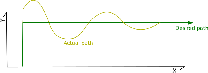
And the discussion has been around reducing the resonance to avoid ringing. That is, there would be an initial deviation, but ideally that deviation would be quickly damped.
One observation I have - can we also avoid the initial deviation?
For example, consider a move of the toolhead along the Y axis to a position of 0.000,20.000 (arriving at time 1.000) followed by a move along the X axis to a position 60.000,20.000. If there is good reason to believe the toolhead will actually be at position 0.000,20.080 at time 1.000, will be at 0.000,20.100 at time 1.010, and will be at 0.000,20.000 at time 1.040 - then could we instead command the steppers to move to position 0.000,19.920 at time 1.000 and then move the stepper to the ultimate Y position of 20.000 by time 1.040.
Such a movement could be thought of as rounding the corners:
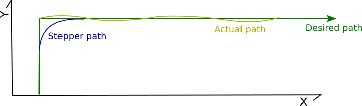
That is, could we deviate the stepper path in anticipation of the toolhead deviation so as to avoid even the initial deviation?
One common observation is that the period of resonance is not constant on a printer - it may change based on Z height and/or X/Y position. I agree this is true, but I'm not sure that "rounding the corners" would ever significantly impact a print. That is, I'd guess that it would be unlikely to introduce new oscillations. Specifically, if the actual frequency is less than the configured frequency then the corner may be rounded by a few microns - but would likely be unnoticeable; if the actual frequency is greater than the configured frequency then the rounding would increase total acceleration time and should still improve overall dampening.
To be clear, the above is all a hypothesis. I definitely don't want to dissuade you from your research. For reference, this idea was also brought up at: https://github.com/KevinOConnor/klipper/issues/57#issuecomment-479549783 . As mentioned then, I still don't know what the math would look like to "round the corners" and the Klipper code isn't ready to handle movement past the nominal ending of a g-code move.
Cheers,
-Kevin
KevinOConnor
on 11 Sep 2019
@KevinOConnor There are a few different practical approaches that already exist to do what you're saying on corners. But they're not simple to implement, in the sense that a lot of very foundational motion control conventions we've inherited from GRBL would have to be reworked.
1) Round off gcode tool path corners in XYZ coordinate axis space, within a tolerance distance. MachineKit does this in the 3-axis path planner. (They do not ever permit corner "jerk" velocity jumps.) You specify maximum X,Y,Z accelerations and a maximum allowed path deviation, and the MachineKit trajectory planner creates a rounded path that stays within those four limits at maximum achievable tool speed.
2) Take each stepper separately (ie one-dimensional joint space) and add offsetting motions to lead the drivetrain elasticity. For example, the stepper stops before the corner so the resulting elastic overshoot doesn't extend as far off-path. Then you "give back" the added motion within the ringing duration so the post-damping path is accurate. This would be like "pressure advance for drivetrains" where you tune an empirical fudge factor.
3) You can switch to a torque-controlled "model feedforward" motor drive scheme where the stepper coil energization angle is manipulated to lead/lag the rotor by the appropriate phase angle to deliver the amount of torque required, at the right times, to produce the desired tool path. In other words implement a form of field-oriented stepper motor control without an encoder. This requires characterizing your hardware pretty thoroughly (mass, damping factor, motor torque, etc). People do this sort of thing in advanced serial robot arm control and some advanced mills, but it's pretty much unheard of in 3d printing and hobby CNC.
4) You can measure the real oscillation (ie do an autotune routine where you dead-reckon position curves from a MEMS accelerometer stream) to get a matrix of tuning factors, and then use that to superimpose the reverse position profile on your motors and attempt to cancel it out. Somebody published a paper on this a few years ago but I can't seem to find it now... they were using this to allow dramatically higher print speeds without losing position, but it would also work for print quality.
rcarlyle
on 11 Sep 2019
Yes LinuxCNC rounds corners to avoid having to come to a dead stop. I don't
think there is much point trying to print a sharper corner than half the
extrusion width.
On Wed, 11 Sep 2019 at 16:32, KevinOConnor notifications@github.com wrote:
@dmbutyugin https://github.com/dmbutyugin - Okay, thanks. The Y axis is
a displacement distance and the X axis is time.One thing I've noticed is that in all of the simulations there is an
initial displacement (the toolhead deviates from the desired path).That is, it is common to see behaviour like the following for a toolpath
that takes a 90 degree corner:
[image: ringing]
https://user-images.githubusercontent.com/3004890/64708898-5a29bd80-d483-11e9-9436-7b9eccf1cb8e.png
And the discussion has been around reducing the resonance to avoid
ringing. That is, there would be an initial deviation, but ideally that
deviation would be quickly damped.One observation I have - can we also avoid the initial deviation?
For example, consider a move of the toolhead along the Y axis to a
position of 0.000,20.000 (arriving at time 1.000) followed by a move along
the X axis to a position 60.000,20.000. If there is good reason to believe
the toolhead will actually be at position 0.000,20.080 at time 1.000, will
be at 0.000,20.100 at time 1.010, and will be at 0.000,20.000 at time 1.040
- then could we instead command the steppers to move to position
0.000,19.920 at time 1.000 and then move the stepper to the ultimate
position of 0.000,20.000 by time 1.040.Such a movement could be thought of as rounding the corners:
[image: ringing-avoid]
https://user-images.githubusercontent.com/3004890/64710106-5d25ad80-d485-11e9-8f8f-02d7123dfbf6.pngThat is, could we deviate the stepper path in anticipation of the toolhead
deviation so as to avoid even the initial deviation?One common observation is that the period of resonance is not constant on
a printer - it may change based on Z height and/or X/Y position. I agree
this is true, but I'm not sure that "rounding the corners" would ever
significantly impact a print. That is, I'd guess that it would be unlikely
to introduce new oscillations. Specifically, if the actual frequency is
less than the configured frequency then the corner may be rounded by a few
microns - but would likely be unnoticeable; if the actual frequency is
greater than the configured frequency then the rounding would increase
total acceleration time and should still improve overall dampening.To be clear, the above is all a hypothesis. I definitely don't want to
dissuade you from your research. For reference, this idea was also brought
up at: #57 (comment)
https://github.com/KevinOConnor/klipper/issues/57#issuecomment-479549783
. As mentioned then, I still don't know what the math would look like to
"round the corners" and the Klipper code isn't ready to handle movement
past the nominal ending of a g-code move.Cheers,
-Kevin—
You are receiving this because you were mentioned.
Reply to this email directly, view it on GitHub
https://github.com/KevinOConnor/klipper/issues/57?email_source=notifications&email_token=AAEKHBOZV5MFQKE7KAAKHN3QJEFSFA5CNFSM4EIJ4S32YY3PNVWWK3TUL52HS4DFVREXG43VMVBW63LNMVXHJKTDN5WW2ZLOORPWSZGOD6O45BI#issuecomment-530435717,
or mute the thread
https://github.com/notifications/unsubscribe-auth/AAEKHBPSFQ64BENDAMLT7FDQJEFSFANCNFSM4EIJ4S3Q
.
nophead
on 11 Sep 2019
@nophead Well, if the nozzle radius / noodle extrusion width geometry rounds off half an extrusion width, and the motion planner also rounds off half an extrusion width, you're going to get something like a full extrusion width real radius at the outside corner... (plus or minus some asymmetrical flow effects.) but I'd be on board with rounding off 5% of the extrusion width or whatever. The LinuxCNC/MachineKit guys are doing like sub-1/1,000th of an inch kind of roundoff tolerances which is visible but not usually creating a fit/function problem in parts.
In my opinion you'd want the max dimension change to be significantly less than the magnitude of ringing you're trying to fix, but that's an opinion.
rcarlyle
on 11 Sep 2019
FWIW, I think I've figured out how to implement the math for the idea I've been describing.
Currently, Klipper implements the kinematic formulas to calculate the stepper position at a given time t, and then uses its "iterative solver" to find each step time given that formula. I think we could update that formula to:
stepper_position(t) = nominal_position(t) + predicted_spring_displacement(t)
That is, if the belts stretch like a stiff spring and thus the toolhead doesn't always match the stepper's position, then we can drive the stepper so as to account for that displacement. The displacement of a spring can be estimated using Hooke's Law:
predicted_spring_displacement(t) = -force(t) / spring_constant
The force can be estimated by assuming it is proportional to acceleration. It wouldn't make sense to use the nominal acceleration (as that wouldn't work well with instantaneous velocity changes), but it should be possible to calculate the average acceleration over a "smoothing window":
force(t) = force_constant * (nominal_velocity(t + smooth_window) - nominal_velocity(t - smooth_window)) / smooth_window
Simplified, that results in:
stepper_position(t) = (nominal_position(t)
    - (nominal_velocity(t + smooth_window) - nominal_velocity(t - smooth_window))
       * stepper_constant / smooth_window)
There would be two constants that would need to be filled in by the user: smooth_window and stepper_constant. The smooth_window could be obtained by determining the resonance period on a test print and then using one quarter of that value. (Using a quarter of the resonance period should help suppress oscillations). The stepper_constant could be obtained by using a "tuning tower" - print a cube that increases the stepper_constant with each level - then find the level with the best results.
Just an idea. The main hold-up on testing this is that Klipper would need to be able to look across g-code moves in order to properly calculate nominal_velocity.
-Kevin
KevinOConnor
on 11 Sep 2019
@KevinOConnor I'd like to clarify one thing about this case you discuss:
That is, it is common to see behaviour like the following for a toolpath that takes a 90 degree corner:
Are you talking about the displacement caused by non-zero corner velocity, or caused by 'overshooting' during deceleration? These are two very different scenarios, I think.
If you're talking about non-zero (large) corner velocity, then I'm afraid it is as the others have said - the corner must be approximated by the arc, and even then it will be impossible to achieve high corner velocities. It is going to be virtually impossible to compensate the displacement with steppers: if you take a look at your scheme and compare the stepper trajectory with either the desired or 'actual' trajectory and try to see which forces will act on the toolhead before the turn, you'll see that the forces the stepper will create along X axis cannot be compensated by toolhead inertia for the toolhead to stay on the vertical line before the turn.
This means the only way for the toolhead to follow the desired path is to come to a complete stop at the corner. To put it another way: if the toolhead must follow the desired or 'actual' path on the picture, it must start the movement along X axis right at the corner, otherwise (if it starts such movement earlier or later) it will deviate from the desired path. But then the velocity of the toolhead along Y axis must also get as close to 0 as possible at the corner - so we get 0 desired velocity at the corner.
But if you're talking about displacement caused by deceleration of the toolhead - I think you're totally right that it should be possible to compensate it by some 'extra' push by the steppers, sort of a 'force advance'. I can only see that this will likely increase the ringing _after_ the corner, because even stronger force acting on the belt(s) will suddenly be released right after the corner. What is probably possible is try to dampen this extra movement along Y axis after the corner with steppers (basically, moving Y stepper in counterphase to the vibrations). But I can see that the math and tuning of the printer will likely get complicated.
BTW, this sort of followed from my analysis above, but I decided to show it more prominently on such square corner how cornering will work with different ao=2, 4, 6. To make sure the picture demonstrates the effects well enough, I took the following parameters: corner_velocity = 0 mm/sec, a=500 mm/sec^2, velocity = 200 mm/sec, ringing frequency = 20 Hz and max_jerk = 6000 mm/sec^3 for ao=4,6. Here's how the cornering looks like:
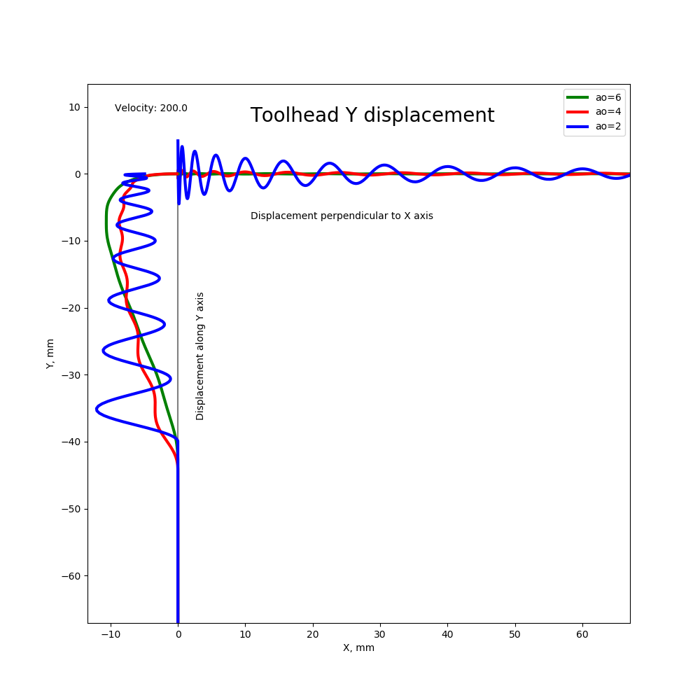
Here X and Y axes are coordinate axes of the print surface, and dimensions are mm. Charts show the toolhead displacement along Y axis, but the scale of displacement is not mm, some abstract magnitude. Also, displacement before the corner (on Y axis) is along Y axis, so the graphs show its magnitude, but in fact the toolhead moves in a straight line before the corner. Still, ringing here before the corner may create uneven extrusions because the toolhead oscillates around it's supposed location. Displacement after the corner (when toolhead moves along X axis) is perpendicular to the X axis, and it shows in print as ringing.
This simulation shows that with ao=2 the toolhead can indeed go outside the corner, exactly as you showed on the picture above, even if the corner velocity is 0 and deceleration is perfectly timed when there are losses in the system. Contrary to that, ao=4 and 6 usually make the toolhead pass almost exactly through the corner, because both of them have 0 deceleration at the end of deceleration and they effectively dampen the vibrations. So S-Curve acceleration with jerk limit can solve the problem of corners too, assuming square_corner_velocity is not too high (if it is high, ugly corners cannot be improved, I believe).
dmbutyugin
on 12 Sep 2019
Are you talking about the displacement caused by non-zero corner velocity, or caused by 'overshooting' during deceleration?
Overshooting during deceleration.
I can only see that this will likely increase the ringing after the corner, because even stronger force acting on the belt(s) will suddenly be released right after the corner.
It wouldn't be a sudden release of belt tension, it would be a release spread over one fourth the resonance period.
What is probably possible is try to dampen this extra movement along Y axis after the corner with steppers (basically, moving Y stepper in counterphase to the vibrations). But I can see that the math and tuning of the printer will likely get complicated.
Yes, that is the idea. My thinking is that the math is not that complicated. The key idea is that the active damping would only be done over one quarter of a resonance period - that is, if the toolhead isn't moving for this period and the steppers move in sync with the release of energy in the spring over this period - then the system no longer has any momentum and there are no oscillations. If my thinking is correct, it would continue to be beneficial even if the amplitude and timing are not exact.
-Kevin
KevinOConnor
on 12 Sep 2019
@KevinOConnor, it's am interesting idea, looking forward to testing it once it's implemented.
On the topic of S-Curve acceleration, what do you think about integrating it with jerk limit patch into the mainline? @BlackStump reported quality improvements over constant acceleration. My simulations show that this is no accident; we can expect quality improvements in ringing and cornering over ao=2, at the price of slower short moves. It also helps if extruder struggles with pressure advance. And simulations show that the tuning should be very simple: in fact, it's sufficient to measure the lowest ringing frequency. But to be on the safe side, one should also tune square_corner_velocity to make sure it does not contribute to the ringing.
dmbutyugin
on 12 Sep 2019
BTW, the pressure advance can be improved for ao=6 I think. Since the toolhead displacement is roughly proportional to the acceleration, the extruder position e_x = r ( x + alpha v - beta a - alpha beta j) with r - extrusion ratio and j - jerk. Beta is a new belts elasticity parameter. Though it can be anisotropic, hard to tune and compute, and generally not worth the effort.
dmbutyugin
on 12 Sep 2019
Question for the group. What magnitude of improvement is worth pursuing here? My thinking is that once the magnitude of print quality disruption due to acceleration order / kinematic jerk decreases significantly below the magnitude of print quality disruption due to velocity jumps, there isn't much point in continuing to optimize.
If acceleration durations are really causing so much ringing due to resonant period matching issues, I'd love to see some analysis on the old constant-velocity printing mode. IE how we used to do the whole print at 30 mm/s with no slowdowns at all.
When you have smoothly-faceted curves with a lot of small segments, S-curve behavior gets weird because each segment is too short for it to make sense to develop the full "S" shape profile. I suspect it may be superior performance to simply run through at a low constant-velocity value and not even bother with more complex motion control schemes. I don't know if klipper has a mode to do constant velocity motion, but I'd imagine you could set acceleration arbitrarily high in ao=2 mode (like 1,000,000 mm/s^2) to effectively get the same behavior.
rcarlyle
on 12 Sep 2019
@rcarlyle just my 2 cents, others may have other perspecitves
If acceleration durations are really causing so much ringing due to resonant period matching issues, I'd love to see some analysis on the old constant-velocity printing mode. IE how we used to do the whole print at 30 mm/s with no slowdowns at all.
This is causing issues with constant acceleration as well, that is why this whole thread was started AFAIU. I think the numeric analysis I made also gives some insights how ringing behaves with ao=2, though of course this is a bit of an approximation of the real life.
When you have smoothly-faceted curves with a lot of small segments, S-curve behavior gets weird because each segment is too short for it to make sense to develop the full "S" shape profile. I suspect it may be superior performance to simply run through at a low constant-velocity value and not even bother with more complex motion control schemes. I don't know if klipper has a mode to do constant velocity motion, but I'd imagine you could set acceleration arbitrarily high in ao=2 mode (like 1,000,000 mm/s^2) to effectively get the same behavior.
This profile is indeed rough for the current S-Curve implementation. Jerk limit is no better now, because even though it allows to develop the full "S" shape, it is at the expense of smaller acceleration. As a future work, I want to implement combining several moves into a single S-shape acceleration profile, to deal with exactly this problem. But it'll take some more time.
dmbutyugin
on 12 Sep 2019
@dmbutyugin I would personally really like to see the S-curve profile span multiple similar-direction segments. Constant acceleration schemes have spanned multiple similar-direction segments since the earliest GRBL days. But there are only seven possible ramp cases to cover for that code within each segment, and you don't need to have any motion parameters match at the corner except perhaps corner speed:
- (coast)
/ (accel)
/- (accel-coast)
/-\ (trapezoid)
/\ (triangle)
-\ (coast-decel)
\ (decel)
Compare to any kind of multi-segment S-curve approach, where you're having to match the instantaneous velocity and acceleration across the corner, and preferably also kinematic jerk direction (but there are a lot of different options here).
rcarlyle
on 12 Sep 2019
From where I stand it actually does not look super complicated. High-level scheme is pretty simple: during forward pass find the longest sequences of moves that can accelerate together, during the backward pass - longest sequences that can decelerate together, and then for each such group generate a single S-curve profile, which can then be split into individual moves - pretty much take the same S-curve coefficients with an appropriate time-offset from the beginning for the curve. This guarantees the smoothness of all derivatives across the move boundaries within the same acceleration or deceleration group.
But with constant acceleration you get this combining for free without extra efforts - the acceleration is the same for all moves.
dmbutyugin
on 12 Sep 2019
@dmbutyugin I'm not familiar with how Klipper does this, but my understanding is that the issue arises from the fact that successive segments have different vector directions. Whichever joint/axis is experiencing the limiting motion within that segment governs the motions of all the others. The motion is planned according to the limiting motor, and non-limiting motors are slowed down proportionately to stay in synchronous 4-axis motion. So you could get a series of accelerating moves where the limiting motor changes halfway through the series. And the non-limiting motors won't necessarily be experiencing an "S" once the limiting motor "S" is generated -- could be various weird squiggle shapes depending on the curvature of the series of segments.
I'm not sure I'm describing this terrible well... I suggest imagining what the motion planner will do for each axis if you print a circle, and if you print a squiggly line that contains no axis-direction reversals.
rcarlyle
on 12 Sep 2019
The way Klipper approaches the motion planning to satisfy these constraints - to be best of my knowledge - is by computing the max cruising speed for each move and max cornering velocity at the move boundaries, which can depend on the move location within the buildplate (e.g. on deltas) and the angle between the moves. This is where 'sequences of moves that _can_ accelerate together' comes from - the acceleration group must stay within the limits of each move and each corner between the moves. If the acceleration would exceed, say, the cornering velocity between two moves, it must be split at that corner into 2 different groups to make sure the constraints are obeyed.
dmbutyugin
on 12 Sep 2019
Ok, right. Imagine you're printing a small, finely-faceted 90 degree circle arc at a 100mm/sec command feedrate.
- Assume the arc is long enough to have all three accel, coast, decel.
- Assume the facets are small enough that it takes many to get up to feedrate.
- At the corners, only a small direction change occurs, so corner velocity is never limiting.
1) The initial move is entirely +X. The motion planner will apply X acceleration limit and no other axis is moving.
2) Then the second segment has some additional Y motion Y<
3) This continues, with X motion decreasing and Y motion increasing. At the 45 degrees of arc point, X=Y, both axis speeds are 70.7mm/s.
4) Approaching the end of the 90 degree arc, the motion planner lookahead will notice the need for 0 feedrate and start decelerating both X and Y. Y axis deceleration will limit and X will experience small decelerations, slaved to Y.
Now imagine the acceleration is lower, so the nozzle does not reach command feedrate until the END of the 90 degree circle arc. X velocity will increase through some portion of the arc, then decrease as the direction of motion changes to Y. The Y axis only accelerates through the arc.
Where do you apply the S profile to these cases? Velocity jumps at corners and direction changes in the path are changing your motion profile to mess up the S. I think this is solvable, but will take some thought and code.
rcarlyle
on 13 Sep 2019
Hmm, maybe I did not fully understand your concern, but let me explain how I see it. Acceleration (be it constant or S-curve) is computed in Klipper for the toolhead, not individual steppers, and along the direction of movement. Velocity or acceleration jumps of the toolhead orthogonal to its direction of movement are not accounted in the planner besides limiting the corner velocity. AFAIU the reason this is ignored is because, even though there is a force changing the direction of the toolhead - it does not make any work because it does not change the kinetic energy of the toolhead. Strictly speaking, this is not true for bed slingers where the toolhead moves along X axis and the bed moves along Y axis - so the change of direction in fact changes the kinetic energy of individual independent parts of the printer. The way Klipper, or most of (any?) other firmware, treats this, is a bit of oversimplification, but that's how it is, and I'm not even sure if there is a way to fix it besides setting corner velocity to 0. So in the end, the steppers themselves do not have to follow S-Curve profile, and indeed may experience jumps in acceleration, velocity, etc.
To answer your question:
- motion plans moves essentially in two sweeps - forward and backward
- during forward sweep it will determine the maximum attainable velocity for each move; in the first case it will determine that starting from n-th move the velocity of the toolhead is 100 mm/s, in the second case it will see that 100 mm/s is achieved at the end of the arc
- during backward sweep it plans deceleration - like acceleration in reverse direction, for each move it determines the maximum velocity such that it can still properly decelerate the toolhead; in the first case it will determine that somewhere after n-th move it should start a deceleration and will plan the following profile velocity profile /-\. In the second case it will determine that it cannot decelerate from 100 mm/s, and instead will find that in the middle of the arc - at 45 degrees - it should start deceleration. Whatever velocity is possible there from acceleration will be the max velocity of the move, so the speed profile is /\. I actually omitted trapezoid generator part - so the profile will actually be /-\ with even lower max velocity.
- now with S-Curve move combining, in the forward sweep phase it will determine that, in principle, all moves can be combined until 100 mm/s is reached - either somewhere inside or at the end of the arc. During the backwards sweep it will try to combine moves into deceleration in the similar manner and will either see that, in the first case, k moves can be combined into single S-curve acceleration and k moves - into deceleration, and the rest will be cruising at 100 mm/s, or, in the second case, find a cross-over point before which all moves will be combined into a single S-profile acceleration and after which - into deceleration. Note that, in principle, trapezoid generator is not very necessary in this case because going from acceleration to deceleration is smooth, unlike constant acceleration.
dmbutyugin
on 13 Sep 2019
@dmbutyugin
On the topic of S-Curve acceleration, what do you think about integrating it with jerk limit patch into the mainline?
Thanks for working on this. I am interested in your tests and results. In my opinion, it isn't yet ready for merging into the master branch.
My main feedback is as before - I think there needs to be a user facing document describing how to test s-curve support. Ideally, this would be a step-by-step type of document - something like "print model X, look at the print for Y and if so then s-curves shouldn't be enabled, otherwise look for Z and if so reprint the test object after doing M, otherwise, measure N and P on the object and set the config using formula ...". I did review your previous document (thanks) but I got the impression you were now considering a different tuning approach (taking into account measuring of resonance).
I think it would be great to see the results of additional test results of the s-curves with jerk limiting. (FWIW, a proscriptive user facing document may help in getting more tests.)
One thing I'm unsure about is the acceleration limitation on short segments in the current jerk implementation. It seems like that may be a notable limitation when printing arcs. If there is a plan to rework that, then I'd like to better understand what that work involves. (It ultimately may make more sense to do that work prior to merging.)
Finally, as a high-level comment, I'll add that I too am concerned with the "double acceleration" that the s-curve code currently produces on short moves. I know this has nothing to do with your recent code - it's a limitation of s-curves in general - and it's been known for a while (eg, https://github.com/KevinOConnor/klipper/issues/57#issuecomment-351913825 ). At a high-level, though, it does weigh on me when considering merging into master.
-Kevin
KevinOConnor
on 13 Sep 2019
@rcarlyle
Where do you apply the S profile to these cases? Velocity jumps at corners and direction changes in the path are changing your motion profile to mess up the S. I think this is solvable, but will take some thought and code.
Yes - quite the challenge.
-Kevin
KevinOConnor
on 13 Sep 2019
@KevinOConnor thank you for the feedback! Yes, I agree that it is premature to integrate the patch into the mainline right now. I just wanted to get an idea what you're looking for as prerequisites: it looked a bit like the initial S-Curve implementation had inherent issues and maybe will have never been accepted into the mainline as the testing strategy is not fully clear. So your opinion on the jerk-limit patch is very important. I'll also see how my progress on the combining s-curve moves will do, I generally agree that it is much better to have the complete implementation prior to merging. I'm just worried a bit that the patch will grow pretty large.
... there needs to be a user facing document describing how to test s-curve support. Ideally, this would be a step-by-step type of document ...
I'll do a few more experiments myself and update the documentation. I have another idea how to improve the acceleration on the short moves, but I need to see how it will work together with PA. And it makes sense only if move combining is implemented.
I think it would be great to see the results of additional test results of the s-curves with jerk limiting. (FWIW, a proscriptive user facing document may help in getting more tests.)
This is a good idea, I'll make sure to add instructions to the documentation how to switch the existing installation to the test branch. This will hopefully make it easier for people to try it out and share their feedback.
One thing I'm unsure about is the acceleration limitation on short segments in the current jerk implementation. It seems like that may be a notable limitation when printing arcs. If there is a plan to rework that, then I'd like to better understand what that work involves. (It ultimately may make more sense to do that work prior to merging.)
Just wanted to stress that it's ultimately not that bad. I've been printing round and curved objects with the current implementation for quite some time now. The acceleration is indeed slower, but it doesn't turn the printer into the turtle when printing curves :)
As for my plans - I am working on the implementation of the move combining again now after writing some docs for the initial jerk-limit feature and doing some numeric experiments. I outlined the high-level idea behind the algorithm above. As for the timeline - I'm not 100% sure how much time it will take - I'm doing this in my free time.
dmbutyugin
on 15 Sep 2019
One thing to keep in mind about finely-faceted arcs is that there is not currently ANY good 3D printer acceleration scheme that handles them well. All the GRBL-derived schemes (corner jerk, junction deviation, whatever) are unable to identify reasonable acceleration slowdowns where the change in direction at the segment vertices is small. Small angle segment vertices do not register enough velocity change to trigger an acceleration slowdown and thus effectively run at full feedrate with no contextual understanding of whether that makes sense for the geometry or not.
In a big arc of 1cm segments at 1 degree direction change per corner, running full speed is fine.
In a tight arc of 0.05mm segments at 1 degree direction change per corner, slowdown is required.
It seems simple to identify this sort of thing ad hoc for circle arcs, but complex organic shapes with a range of segments lengths and direction changes (like a face, or text embossed on a sphere) create a fairly complex identification problem for the motion planner. No one has really tackled this yet to my knowledge.
So we pretty much universally compensate in the slicer by slowing down perimeters on curvy/organic prints — setting feedrate below the safe constant-velocity speed for the printer. It’s a learned common knowledge behavior that barely anyone realizes is an artifact of GRBL planner algorithm shortcuts required to run real-time motion on an Atmega 328p.
Klipper is probably the best platform to tackle this. But it’s big!
The thought I’ve been kicking around for a long time is chunking segments into batches of left-turns and right-turns (to find arcs) and calculating a local multi-segment curvature-tightness parameter over a certain linear distance in the look ahead queue (perhaps the distance to accelerate up to feedrate) and then applying a radial acceleration limit to that. But I wouldn’t have the foggiest idea how easy or difficult that is to implement.
rcarlyle
on 16 Sep 2019
An example of printing a fairly small object with arcs at 60 mm/sec (30 mm/sec outer perimeters), max_jerk=90'000 mm/sec^3, true speed:
dmbutyugin
on 16 Sep 2019
@rcarlyle
In a big arc of 1cm segments at 1 degree direction change per corner, running full speed is fine.
In a tight arc of 0.05mm segments at 1 degree direction change per corner, slowdown is required.
Klipper should handle this - see PR #255.
-Kevin
KevinOConnor
on 16 Sep 2019
@KevinOConnor See, that's what I like about you guys, you're always coming up with good stuff! That seems like a pretty elegant solution that would cover the vast majority of real print geometry that is mishandled by the original Junction Deviation code.
I am wondering if it will significantly underspeed gentle corners in certain edge cases. Imagine a fairly large, coarse polygon (say n=12) but each polygon corner where sides should intersect is replaced with two very short segments which are more or less colinear with the sides. The circle radius calculated on the entire polygon may be very large, but the circle radius calculated at the unnecessarily-segmented corner would be very small. It isn't hard to get short nearly-colinear segments near corners like this if the slicer exactly maps gcode to the STL slice without decimation.
rcarlyle
on 16 Sep 2019
In any case, intermittent conservative underspeed is a vastly better printer behavior than pathological overspeed.
Does Klipper combine colinear or nearly-colinear segments? (MachineKit/LinuxCNC does. I don't particularly care for that behavior but it's important to machine speed when you have to stop at corners like their 4+ axis motion planner does.)
rcarlyle
on 16 Sep 2019
I think that is exactly the shape one would get by expanding a polygon slightly with offset() in OpenSCAD. The corners get rounded with short segments and if a silly value for $fs was used they could be very short.
nophead
on 16 Sep 2019
I am wondering if it will significantly underspeed gentle corners in certain edge cases.
Probably best to move this conversation to #255. To answer your question though, yes - Klipper would pessimize the cornering speed in that case. It was known, but thought to be an acceptable risk.
-Kevin
KevinOConnor
on 16 Sep 2019
All, about time to chime in again. I've created a physics based simulation for modeling 3d printer toolhead deviation during movements. It currently supports the klipper planner and running from GCode (but only run 1 layer or less! it takes awhile to process) example gcode can be found in the examples folder.
The biggest issue with SCurve acceleration is that to achieve it's performance benefits acceleration must be tuned down compared to constant acceleration. However, in standard printing, acceleration times differ on almost every move, exacerbating vibrations under any acceleration profile. I briefly talked about dynamic acceleration above and it's something Duet firmware has implemented. But in real world scenarios it's basically the only thing that can work to reduce vibrations.
The code is here: https://github.com/Islandman93/3dprintersim. I'd prefer not to link images in this issue since it makes comments too large but the run comparisons are under https://github.com/Islandman93/3dprintersim/tree/master/runs. The code currently supports constant, smoothstep, smootherstep, and dynamic accelerations and will print out the average toolhead error after running so comparisons can be made for all types.
I've integrated the dynamic acceleration modifications into a version of klipper I've been running on my own printer for awhile. It works fine, nothing life changing but some improvement (10% maybe) over constant acceleration. I'll try to submit a pull request to open up conversation sometime this week, as well as provide more documentation and examples on the 3dprintersim.
Islandman93
on 17 Sep 2019
@Islandman93 can you test my scurve-jerk-limit branch to compare with constant accel and your changes? If you don't want to spend too much time tuning it, just add acceleration_order = 6, max_jerk = 30 * your_max_accel, and square_corner_velocity=1 values to [printer] section and print some test model, for instance the one created by BlackStump https://www.thingiverse.com/thing:3847206. My version should not require precise timing and tuning, so it can be fine just like this. Limiting corner velocity is normally not required, but I ask to set it to 1 for testing to make sure it does not induce ringing by itself, then jerk limit would not help of course.
dmbutyugin
on 17 Sep 2019
And if you can spend some time tuning, you could measure the ringing frequency
- print the test model at high velocity for outer perimeters V (mm/sec), accel, higher square_corner_velocity and acceleration_order=2
- measure the distance D (in mm) between N oscillations near the notches, preferably skipping the first oscillation or two
- compute the ringing frequency = V * N / D
- compute better max_jerk = 0.6 * max_accel * ringing_frequency
And print the test model with improved max_jerk and acceleration order 4 and 6
dmbutyugin
on 17 Sep 2019
Just if you use bed meshing, better disable or limit it by Z to 2-5 mm from buildplate for testing.
dmbutyugin
on 17 Sep 2019
@dmbutyugin I've integrated your changes into the 3dprintersim and props to you they seem to work really well. Use the flag -at jerk-limited-smoothstep to run it.
Quick comparison of current methods, these are all run using the following command:
python main.py klipper ./examples/test.gcode 50 1000 0.032 0.032 5 -at <accel_method> -o 0 -5
I've also run the test on the flexi_rex example GCode with similar results.
| Acceleration Type | Error (mm/s) | Time (seconds)
| ------------- | ------------- | ------------- |
| Constant | 0.0476 | 1.314
| Smoothstep | 0.0445 | 1.314
| Dynamic | 0.0416 | 1.265
| Jerk Limited Smoothstep | 0.0270 | 2.233
With these parameters smoothstep performs slightly better than constant acceleration, but we know this isn't always the case depending on the period or ringing for a specific printer and acceleration.
IMO @dmbutyugin's solution is probably the closest to something that I would personally use, there are definitely times where I'm willing for a print to take up to 2x longer just to have the best quality possible. In terms of "S-Curve Acceleration" it's also the only solution that has gotten good performance, at the cost of time sure, but TANSTAAFL.
Islandman93
on 18 Sep 2019
@Islandman93 thanks for your analysis! It's good to see an extra confirmation. We'll need more tests in-hardware though. Especially after the move combining is ready.
@BlackStump since you've done the test prints already, could you measure and calculate the ringing frequencies over X and Y axes? If you remember the printing velocity, that is. And which max_jerk value did you choose in the end from the tests? I'm trying to get a bit of statistics for the calculations of the parameters.
dmbutyugin
on 19 Sep 2019
@dmbutyugin
sorry I no longer have the printed test models. ooops I had test prints everywhere so had a cleanup.
I will reprint in a couple days
BlackStump
on 19 Sep 2019
@dmbutyugin Hi, I think there is an issue in your jerk-limited branch :
I get "Option 'min_jerk_limit_time' is not valid in section 'printer'" (I updated right now)
in the source, the only place where I can grep this parameter is in "toolhead.py" and docs.
 aschor
on 21 Sep 2019
aschor
on 21 Sep 2019
@aschor sorry about that. Did you add this option to printer.cfg? Can you post your klippy.log of unsuccessful startup? I can take a look and fix what's wrong. This should've been an optional parameter.
dmbutyugin
on 21 Sep 2019
Anyway, I think it should be fixed now.
dmbutyugin
on 21 Sep 2019
@dmbutyugin can you post some info how to test your work?
cosminr86
on 22 Sep 2019
@cosminr86 you can refer to this doc. I updated it to include the instructions how to switch a branch in your Klipper installation and enable S-Curve acceleration. It also includes some instructions how I think it can be tested and tuned. Your reports - your measured ringing frequencies, max_jerk and min_jerk_limit_time values have they been changed, and the quality impact - are very much appreciated.
BTW, I made some changes which should have improved the acceleration on very short moves, and it would be great if they were tested by somebody besides me as well. They are enabled only if min_jerk_limit_time is set in the configuration, alongside or instead of max_jerk limit. The current suggestion is to set min_jerk_limit_time = 1.0 / ringing_frequency (see more in the tuning doc).
dmbutyugin
on 22 Sep 2019
@dmbutyugin Hi, I think there is an issue in your jerk-limited branch :
I get "Option 'min_jerk_limit_time' is not valid in section 'printer'" (I updated right now)
in the source, the only place where I can grep this parameter is in "toolhead.py" and docs.
Anyway, I think it should be fixed now.
Sorry, it was night here
I did put the parameter manually today to take the logs (Vs copy paste yesterday) .... and this time it works oO.
I'm fetching latest commits just in case ^^. Thank you for your work !
aschor
on 22 Sep 2019
@aschor it should work without this parameter like before. But if you set it, be sure to check out the docs which value to put there.
dmbutyugin
on 22 Sep 2019
I'm testing right now, but I face an issue : my extruder seems to rattle. I have a bowden clone BMG 0.55 pressure advance), on tmc2208 in spreadcycle mode, 0.71A configured (and x4 microstepping with interpolation). I'm changing values on the fly for pressure advance and max_jerk, but I seem to have to go very low on jerk/PA for the extruder not to rattle. I'm on 6AO. current settings not rattling too much : PA 0.3/ max_jerk 60000. max_accel is 3000. I'm not sure if I should remove min_jerk_limit_time parameter, increase stepper current, remove interpolation, or ....
If I set PA=0, my max_jerk before any (light) ringing start is 120000. I have square_corners to 10.
aschor
on 22 Sep 2019
Which value did you put as min_jerk_limit_time? Also, try setting it to 0 to make sure it's not causing problem. I have a similar setup with you, use PA~0.6-0.7, max_accel=3000, min_jerk_limit_time=0.02 which corresponds to max_jerk=90000, 0.9A current. It works, well, OK with PA.
Generally, If you're facing problems with PA and extruder, there's a chance you'll have to tune down max_jerk below what it should be to avoid ringing. I imagine that AO=2 will not work well at max_accel=3000 and PA 0.55 either.. At least, for me it does not work well at all.
dmbutyugin
on 22 Sep 2019
I have just finish a couple of prints with finished settings of
min_jerk_limit_time=0.02127
max_jerk=88920
pa=0.2
extruder is quiet
X was 46-49Hz
Y was 37-42Hz
I am also using a clone BMG extruder but I am using 16 microsteps
BlackStump
on 22 Sep 2019
Which value did you put as min_jerk_limit_time? Also, try setting it to 0 to make sure it's not causing problem. I have a similar setup with you, use PA~0.6-0.7, max_accel=3000, min_jerk_limit_time=0.02 which corresponds to max_jerk=90000, 0.9A current. It works, well, OK with PA.
Generally, If you're facing problems with PA and extruder, there's a chance you'll have to tune down max_jerk below what it should be to avoid ringing. I imagine that AO=2 will not work well at max_accel=3000 and PA 0.55 either.. At least, for me it does not work well at all.
I have
min_jerk_limit_time: 0.02
acceleration_order: 6
square_corner_velocity: 10
max_accel: 3000
with no ringing at all.
But from what I see I should up the motor's current ? I'll have a test with min_jerk_time=0 and play with realtime motor current tuning and P.A (and jerk) see if it changes anything.
aschor
on 22 Sep 2019
TBH, the current settings do depend on the stepper motor. My 0.9A is for this stepper, so YMMV. Also, at the current around 1A it is recommended to have some active cooling for TMC2208.
Which settings do you usually use with AO=2 for PA and acceleration?
But please try setting max_jerk=90000 and min_jerk_limit_time=0 and see how it works. If it does not help, I'm afraid you'll have to keep the current min_jerk_limit_time=0.02 and tune down max_jerk. Or tune down PA. That's how it generally is with PA, unfortunately.
dmbutyugin
on 22 Sep 2019
For the reference, I use 16x microstepping on extruder as well. My current bowden one is BMG clone from Trianglelab.
dmbutyugin
on 22 Sep 2019
TBH this is a new printer, I have no usual setting for A0=2 and PA :/
Just tried to up current to 0.9A, and lower max_jerk to 10000, still strange noises. I'll make more tests, I'll also unmount the BMG maybe there is some play in it somewhere (or maybe it just needs some grease). It's a trianglelab too.
aschor
on 22 Sep 2019
Yes, checking for play and that everything's aligned is a good idea.
dmbutyugin
on 22 Sep 2019
Hi.
Thanks for the link. I was testing your moddifications and I found them verry good.
Print qulity greatly incresed.
On my printer I have ringing frequency:
x = 50-65 Hz
y = 32-40 Hz
Print speed 100, acceleration was set to 3000 and square corner velocity to 20, vase mode.
With min_jerk_time: 0.0243 and square corner velocity to 1 have no ringin, max_jerk was at the default settings.
With min_jerk_time: 0.025 ringin start to appear at square corner velocity above 3.
Now I am testing with the fine tune settings
min_jerk_limit_time: 0.0157
max_jerk: 71100
square_corner_velocity: from 1 to 12.
Bottom is without min_jerk_limit_time and top is with min_jerk_limit_time: 0.0243
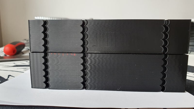
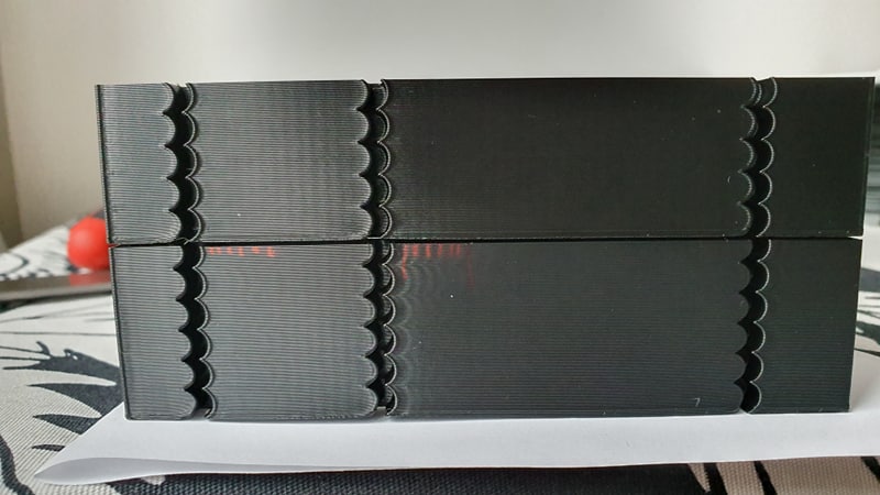
Do you need any other info or testing?
Thank you for your great work!
cosminr86
on 22 Sep 2019
@cosminr86 so the top photo is the side of the model printed along Y axis, is that correct? I see that you chose
min_jerk_limit_time: 0.0157
max_jerk: 71100
close to the recommendations about min and max ringing frequencies from the doc, right? Which acceleration_order did you use? Also, was the bottom model in both pictures printed with acceleration_order > 2 or with acceleration_order = 2? I did not get from
Bottom is without min_jerk_limit_time and top is with min_jerk_limit_time: 0.0243
if min_jerk_limit_time is the only difference and acceleration order was the same or not.
If you don't put anything besides the acceleration_order into the config, the default will be min_jerk_limit_time = 0 and max_jerk = 30 * max_accel (90'000 mm/sec^3 in your case). I guess that's a bit too much for this printer.
Can you also print the test model with acceleration_order = 2 and the normal max_accel=3000? You can use the same square corner velocity = 1 mm/sec. I'd be curious to see the difference in print quality of the default constant accel code vs jerk limit (default values) vs jerk limit tuned.
dmbutyugin
on 22 Sep 2019
the bottom one (with marker lines) was printed with AO = 2, 3000 acceleration, square_corner_velocity 20, no jerk settings in the printer.cfg
the top one was printed with AO = 6, 3000 acceleration, square_corner_velocity 1, min_jerk_time: 0.025.
So do you want a test print like this ?
acceleration = 3000
square_corner_velocity = 1
AO = 2
min_jerk_limit_time: 0.0157
max_jerk: 71100
cosminr86
on 22 Sep 2019
one question: does acceleration affects ringin frequency?
cosminr86
on 22 Sep 2019
Ringing frequency is the property of the printer - the rigidity of different parts - so it should not change. But visibility of ringing with AO=2 does change as acceleration increases. Ringing with AO=4,6 is much less (if at all) impacted by max_accel.
the bottom one (with marker lines) was printed with AO = 2, 3000 acceleration, square_corner_velocity 20, no jerk settings in the printer.cfg
All right, thanks, I was indeed confused.
So do you want a test print like this ?
acceleration = 3000
square_corner_velocity = 1
AO = 2
min_jerk_limit_time: 0.0157
max_jerk: 71100
I guess no need then: with AO=2 the last 2 parameters have no effect and are ignored. Although we could see the difference between 20 and 1 square corner velocity - how much it impacts ringing. But I take it that you will fine-tune the square corner velocity for AO=6 anyway.
dmbutyugin
on 22 Sep 2019
Although, @cosminr86 could you print a test with just the following parameters:
AO=6
max_accel=3000
square corner velocity = 1
without supplying min_jerk_limit_time and max_jerk in the config? So they will be assigned the default values. I wonder how good or bad the default values are.
dmbutyugin
on 22 Sep 2019
I'am on it.
I was reprinting the test with following settings
AO = 2
acceleration = 4000
square_corner_velocity = 20
I got more closer riging frequency: for x axis = 40.98 for y axis = 40.65
cosminr86
on 22 Sep 2019
the default settings are pretty good, but still needs tunning.
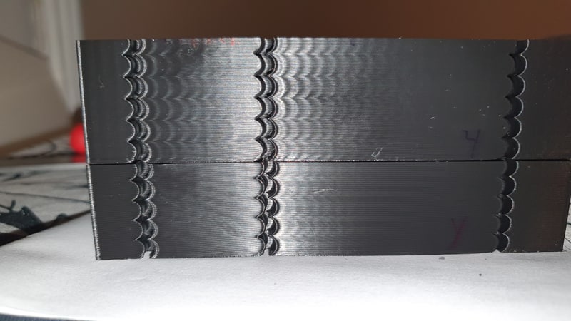

top: ao = 2 square_corner_velocity = 20 acceleration 3000
bottom: ao = 6 square_corner_velocity = 20 acceleration 3000
cosminr86
on 22 Sep 2019
@dmbutyugin
how does https://github.com/KevinOConnor/klipper/pull/1997 affect your s_curve patch?
BlackStump
on 23 Sep 2019
@BlackStump, @cosminr86 thanks for your tests! Your results show that the tuning instructions are reasonable, I think. As for default settings - they cannot be really made perfect for everybody out of the box. My goal is to have something that at least shows better results than AO=2, but there will be, of course, room for tuning.
As for #1997, I do not fully know yet how it will affect my patch. From the looks of it, it should be compatible with the changes I've pushed to my WIP branch so far. As for the changes I'm working on - well, I did not get in my work to the extruder part yet. It may even simplify things a bit, although I'm afraid that this PR will just push the complexity down to the C-code part of the extruder kinematics. At any rate, I should be adapting the scurve combine code to it. I'm going to leave the current branch at its current state and just fix issues should they be discovered, and continue the development of combining S-Curve moves in another branch. The current code seems to be usable already, and that way I will not be breaking people's setup every now and then if they want to use the current code as-is.
dmbutyugin
on 23 Sep 2019
@dmbutyugin
good plan give a shout when your other branch is ready for testing.
BlackStump
on 23 Sep 2019
Gave it a try. The results are promising. I defo noticed improvement in quality at higher than usual acceleration settings and print speeds. Well, at least when printing your test file.
I tried to print an xyz calibration cube and found two things:
1) setting AO to 6 causes blobs on edges of the X and Y letters
2) with AO set to 2 the blobs disappear but I end up with a failed print due to an 'Internal error on command:"G1"' error
My current settings are:
[printer]
kinematics: cartesian
max_velocity: 300
max_accel: 1000
max_z_velocity: 5
max_z_accel: 100
square_corner_velocity: 20.0
acceleration_order: 2
min_jerk_limit_time: 0.036
 drelich
on 23 Sep 2019
drelich
on 23 Sep 2019
It would be great if you could post the klippy.log for the crashed print. I want to be sure that AO=2 is not broken accidentally. Also, you could post the picture of the blobs on letter edges? I wonder if they could be related to insufficient pressure advance?
dmbutyugin
on 23 Sep 2019
It would be great if you could post the klippy.log for the crashed print. I want to be sure that AO=2 is not broken accidentally. Also, you could post the picture of the blobs on letter edges? I wonder if they could be related to insufficient pressure advance?
ShohninDmitriy
on 24 Sep 2019
It would be great if you could post the klippy.log for the crashed print. I want to be sure that AO=2 is not broken accidentally. Also, you could post the picture of the blobs on letter edges? I wonder if they could be related to insufficient pressure advance?
Here's the photo:
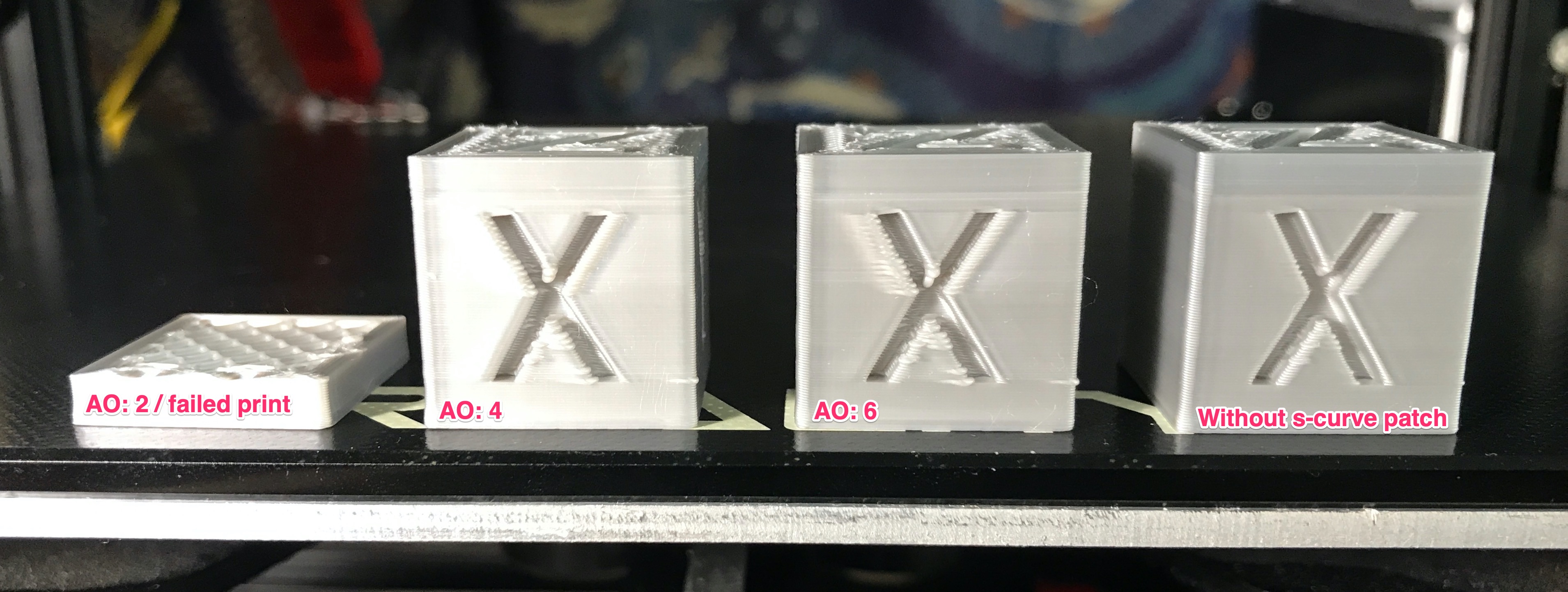
All prints at 100mm/s speed, 1000 mm/s acceleration, corner speed @ 20, PA: 0.5, PA look ahead: 0.010. Using 0.5mm nozzle, ERYONE silk silver PLA on an Ender 3.
The print with AO: 2 fails the moment it hits a few short travels. I'll clean the klippy log and retry printing so that the log is not full of previous print junk, etc.
drelich
on 24 Sep 2019
Thanks @drelich
The print with AO: 2 fails the moment it hits a few short travels. I'll clean the klippy log and retry printing so that the log is not full of previous print junk, etc.
It's all right, no need, I saw the error in the logs. It should not be like that, I'll take a closer look later. You can attach your gcode however, because it looks like a bug in the queue planning, and the dumped moves may be insufficient to reproduce the problem. And it may take me some time to stumble across the problematic sequence myself.
I'm not fully sure about the problems with AO=6 however. I will also try to print it myself. What would help is if you could print that cube with bed meshing disabled and check if this changes anything. The cube is pretty small, so hopefully it can be printed carefully without crashing the toolhead into the bed even without bed meshing. It is known to cause issues with the current version of S-Curve patch with jerk limit.
dmbutyugin
on 24 Sep 2019
I'm not using bed meshing. The klippy log above is from another user, haha.
I've re-applied the s-curve patch and tried to print with AO: 2 and it actually got past the layer where it usually stopped but started having extrusion problems (gear skipping) mid-print so i'll try again. Whoever said 3d printing is a lot of fun lol
drelich
on 24 Sep 2019
Ah, right! Well, then please post the log of your crash! In the future, it's fine to post a log without further cleanup - just be sure to obtain it before the Raspberry restart - the sooner after the crash the better.
dmbutyugin
on 24 Sep 2019
just off AO=2 on the mcu error log above in the comments-enabled imprints normally
ShohninDmitriy
on 24 Sep 2019
just off AO=2 on the mcu error log above in the comments-enabled imprints normally
Um, can you clarify what you mean?
dmbutyugin
on 24 Sep 2019
Right. Extruder problem solved (good ol' clog). Print stopped this time. Klippy log attached.
EDIT: Replaced the .5mm nozzle with a .3mm piece. Managed to print the whole cube no problem.
EDIT 2: Disabled pressure advance and put back .5mm nozzle. Failed in the same spot (more or less). NOTE: The printer basically just freezes, can't work with the menu on the printer's display board.
EDIT 3: Tried to print PETG with a .3mm nozzle and it didn't even make it through the brim and it stopped again. Think I'm gonna stop experimenting and get back to actual printing, haha.
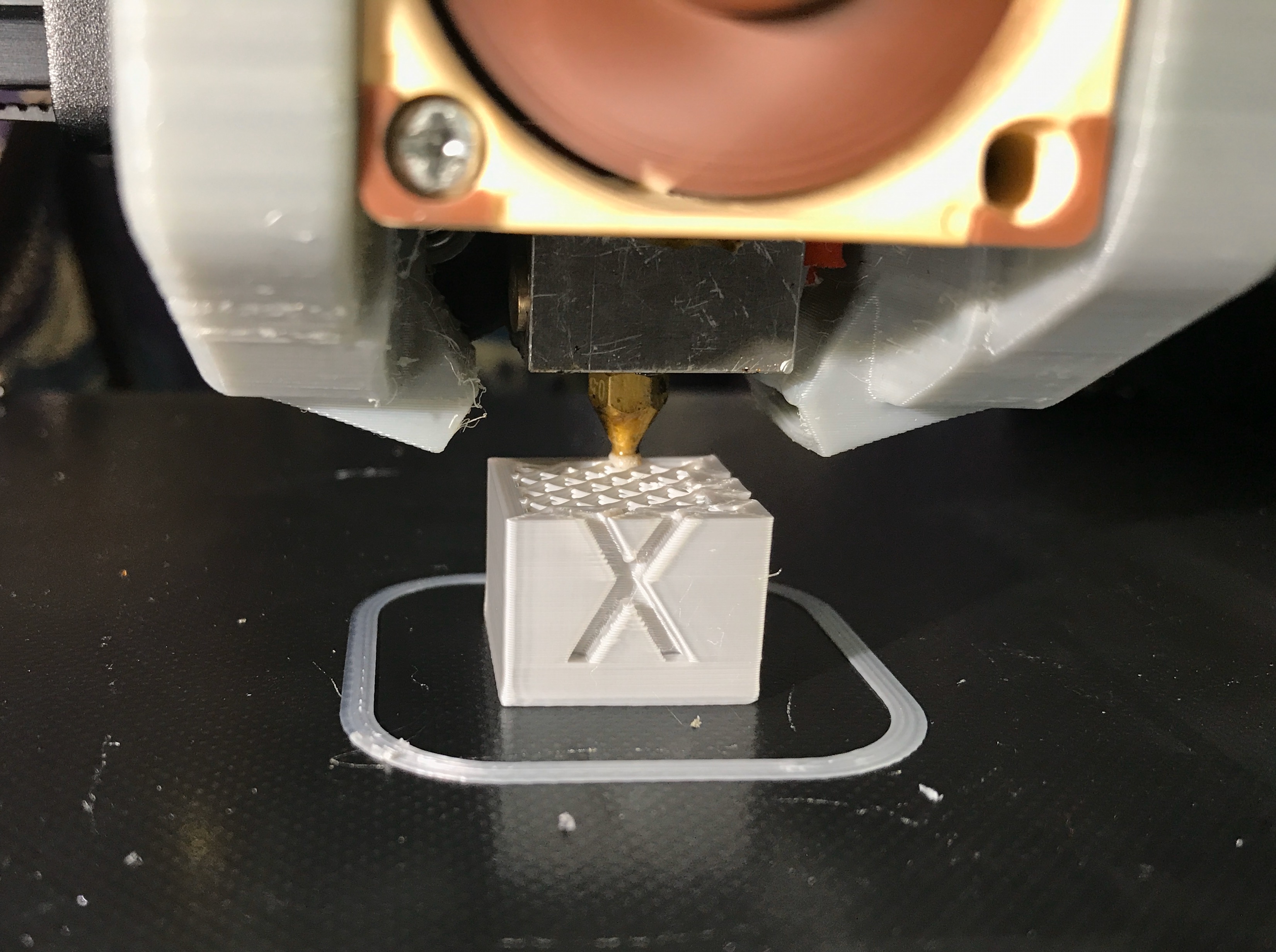 drelich
on 24 Sep 2019
drelich
on 24 Sep 2019
@dmbutyugin we should return pa with changes in ao, right?
As far as I saw in my prints, pa does weird things as the acceleration is changed (more acceleration on the infill less on the walls)
cosminr86
on 24 Sep 2019
@drelich could you also share gcode?
@cosminr86 I think you can re-enable PA, but perhaps you need to re-tune it.
dmbutyugin
on 24 Sep 2019
@dmbutyugin Sorry, that gcode file is gone already. I always discard them after printing. But when I get back to testing this stuff, I'll make sure to post both the log and the gcode files. Cheers.
drelich
on 24 Sep 2019
Ah, all right, never mind, fortunately I was able to reproduce the issue from the small gcode snippet from the logs. Quite fortunate!
dmbutyugin
on 24 Sep 2019
It's actually funny. I added some sanity checks to the Klipper code to make sure I do not add bugs myself; they validate that the velocity is smooth on the boundaries between the moves (basically, that the end velocity of the previous move is the same as the start velocity of the next move). But since these new checks are executed in AO=2 mode in my branch as well, they apparently caught the bug that exists in the mainline code. I actually managed to reproduce it with the master Klipper branch by adding only these checks. I pushed a fix to my branch, feel free to test it. Then I'll create a PR for the master Klipper branch.
dmbutyugin
on 24 Sep 2019
Amazing! I'd love to have your knowledge, haha! Need to finish a print, it'll take until late hours. But I'll install the s-curve patch tomorrow and give it another try! Cheers.
drelich
on 24 Sep 2019
I had notice a big slowdown and a "jerky" moves when printing small perimeters
My bad, with the kevin master branch is doing the same.
cosminr86
on 28 Sep 2019
@cosminr86 can you elaborate? Is this something new? And what do you mean by 'small perimeters'?
dmbutyugin
on 28 Sep 2019
I just edited my post.
On verry small moves, the extruder "jumps" from one end to the other.
cosminr86
on 28 Sep 2019
Still, is this slowdown something new? I did sync my branch to the mainline recently. On the other hand, my branch has sanity checks that the toolhead velocity should not have jumps - so the velocity changes must be smooth.
On verry small moves, the extruder "jumps" from one end to the other.
So, is it like a retract cycle? Does increasing ADVANCE_LOOKAHEAD_TIME help in any way?
dmbutyugin
on 28 Sep 2019
I did not notice it untill now, or maybe this part have some problems.
The problem occures on high density infill (50%) on a small area ~ 5 mm.
I will try to mess with ADVANCE_LOOKAHEAD_TIME later
cosminr86
on 28 Sep 2019
FYI, I did try the implementation I mentioned at https://github.com/KevinOConnor/klipper/issues/57#issuecomment-530435717 and https://github.com/KevinOConnor/klipper/issues/57#issuecomment-530571599 . Details at PR #2030. This github issue has gotten a bit unwieldly, so feel free to comment on this at PR #2030.
-Kevin
KevinOConnor
on 1 Oct 2019
@KevinOConnor that's really interesting! I was inspired by that comment comment of yours, and - sorry to jump in - was also experimenting with the idea.
I made some experimental code based on the idea of acceleration compensation - basically, the toolhead is offset from the commanded position proportionally to -acceleration of it. Then in S-Curve mode we can compensate for it by using a new commanded position r_new(t) = r_old(t) + β a_old(t). Math simulations showed that with perfect β we can fully nullify the toolhead displacement from the expected position (I omit the pictures from simulations to not bloat the post too much). In fact, without a strict proof, the perfect β = 1 / (2 π f)^2 with f - the resonance frequency.
The code I prepared is very experimental. It's not too bad per se, but the approach has certain limitations:
- works well only if the resonance frequencies on X and Y axes are close (I'd say the difference between min and max frequency should be not larger than 30-40%);
- rather sensitive to tuning the compensation parameter β (unlike jerk limit), it should preferably be within ~20% of optimal value for each axis;
- can compensate only acceleration along the move direction, does not handle centripetal acceleration, does not help with cornering velocity;
- supports well only AO=6; although AO=4 is also implemented, I would not recommend it;
- on the other hand, it works for printers with any kinematics.
Honestly, I am not sure if this approach has a future potential. Kevin's PR #2030 is more flexible I believe. Still, if some of you folks will be testing Kevin's branch, I encourage to test my experimental code too - in the hope it will help to improve the feature overall. What you can expect: after tuning the compensation parameter you should be able to push max_jerk value up quite a bit.
How to test it:
$ git remote add s-curve-exp https://github.com/dmbutyugin/klipper.git
$ git fetch s-curve-exp
$ git checkout s-curve-exp/scurve-accel-comp
The feature is controlled by accel_compensation parameter in [printer] section, or via SET_VELOCITY_LIMIT ACCEL_COMPENSATION=.... For example, for 50 Hz accel_compensation ~= 0.00001 (sec^2). If the ringing frequencies are different, choose a value in between, closer to higher frequency - this will overcompensate the higher frequency, and undercompensate the lower frequency.
On my delta with square_corner_velocity=10, accel=5000, accel_to_decel=3000, jerk_limit=1'500'000 (pretty much no limit), no PA, and printing speed 100 mm/sec:
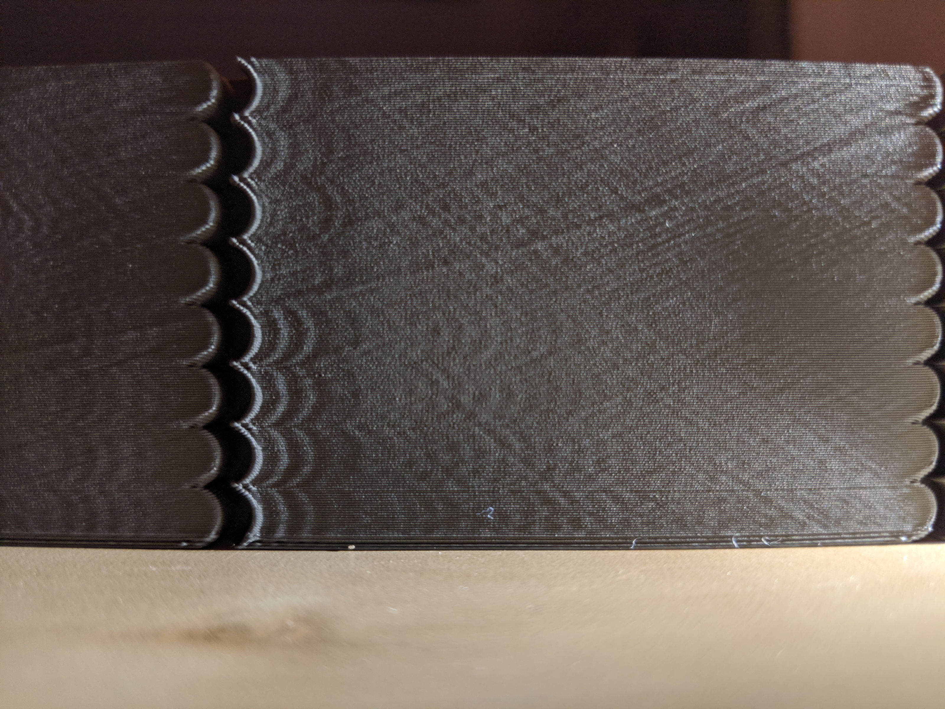
bottom to top:
- 4x 5mm layers - AO=6 no compensation,
- 2x 5mm layers - AO=6 accel_compensation=0.000011,
- 2x 5mm layers - AO=2
The results for AO=6 accel_compensation=0.000011 are better than even AO=2, even though AO=2 in this case has close to perfect acceleration timing for my printer (90 / 5000 = 0.018 sec -> 55 Hz, and the ringing frequency is ~50 Hz -> 0.02 sec).
@Islandman93 it would also be interesting to see the results of testing this new code in your 3dprintersim.
dmbutyugin
on 2 Oct 2019
@dmbutyugin
FYI config
[printer]
kinematics: cartesian
max_velocity: 300
max_accel: 3800
min_jerk_limit_time: 0.02127
max_jerk: 88920
max_z_velocity: 20
max_z_accel: 150
acceleration_order: 6
square_corner_velocity: 6
accel_compensation: 0.00002
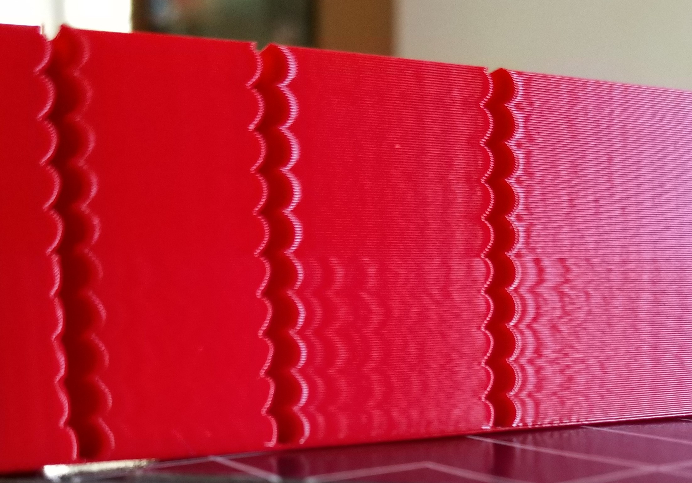
print speed 100mm/s
AO6 top half
AO2 bottom half
btw I added some models to improve printing time
https://www.thingiverse.com/thing:3847206
BlackStump
on 5 Oct 2019
@BlackStump You can try to increase max_jerk from the suggested value when acceleration compensation is active.
dmbutyugin
on 5 Oct 2019
@dmbutyugin
Jerk 100k at bottom increasing 100k to 1000k top
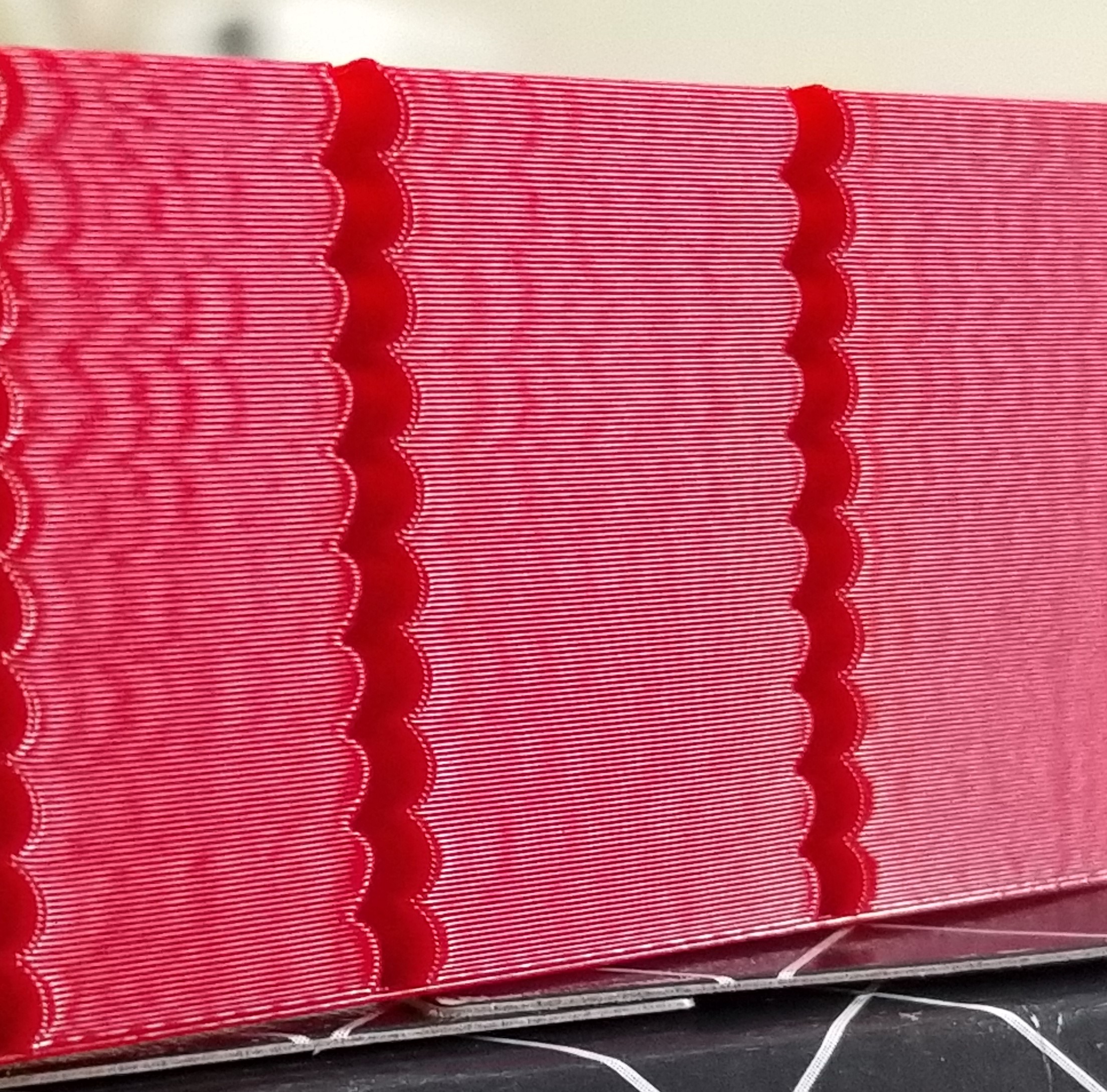
Jerk 44460 increasing by 44460 to 444600 at top
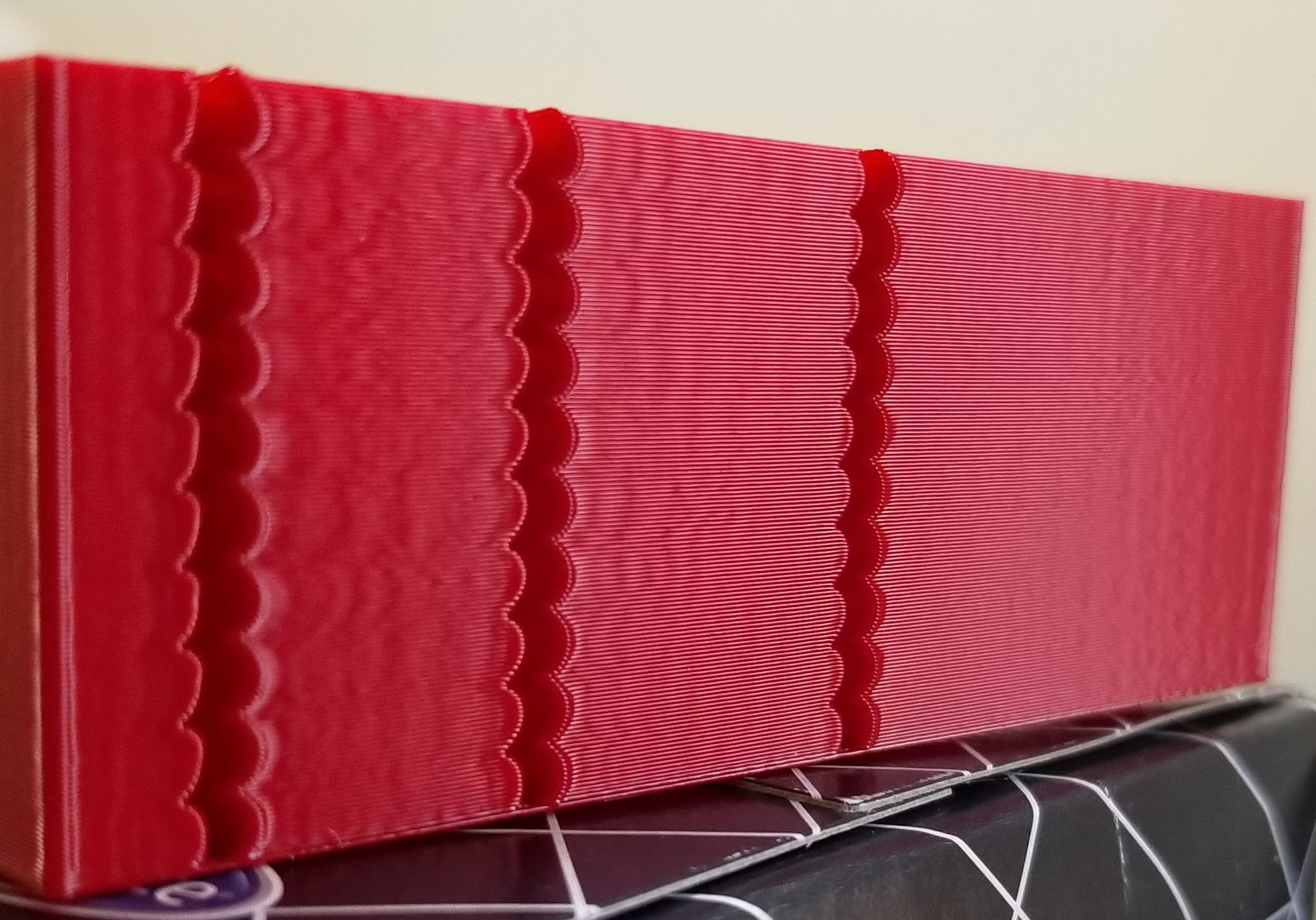
BlackStump
on 5 Oct 2019
@BlackStump I appreciate your help testing this!
You can tell better, but it sounds like you should be able to reach ~300'000 max_jerk with this without degradation in quality. Which is not bad compared to 88'920 you ended up with otherwise.
On a separate note, if the numbers you quoted earlier are right
X was 46-49Hz
Y was 37-42Hz
then it sounds like accel_compensation: 0.00002 is a bit too much. Did you do some testing to come up with this number? From these frequencies, the theory suggests 0.000013 - 0.000016 (my guess would be around 0.000014). You could also tune this parameter by setting SET_VELOCITY_LIMIT ACCELERATION_ORDER=6 JERK=1000000 or more, and print the test model gradually increasing parameter SET_VELOCITY_LIMIT ACCEL_COMPENSATION=... from, say, 0.00001 to 0.00002 and find the sweet spot when ringing is minimal on both axes. Then you can lower max_jerk to eliminate the remaining ringing.
dmbutyugin
on 5 Oct 2019
@dmbutyugin
I agree that approx ~300000 is a nice increase with no quality degradation.
I actually dont know how I got to accel_compensation: 00002 most likely bad math on my behalf.
I had planned tomorrow to try find a sweet spot and your advice is greatly appreciated.
You work is without a doubt a improvement.
I am using the 3mmx10 model as it prints reasonable quick, the 2mm model is even quicker but a tad hard on my eyes.
BlackStump
on 5 Oct 2019
@dmbutyugin @KevinOConnor
I tried to compare AO2 to AO6 with both having the same layer times of 7.1 seconds
The notches are 3mm spacing or 10 layers at 0.2mm layer height each 3mm notch took 71 seconds
bottom 2 notches (0-6mm) are AO6
the next 2 notches (6-12mm) height are AO2
next 2 notches AO6 then AO2 then top 2 notches AO6
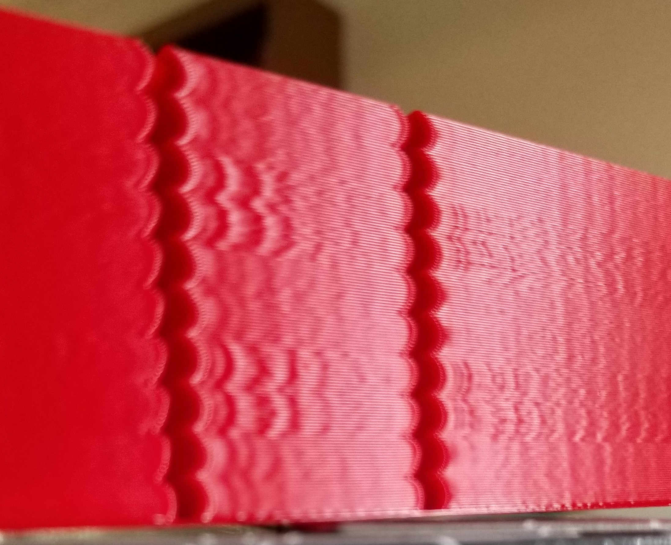
the print speed was 100mm/s for AO6 and 90mm/s AO2
Jerk for AO6 was 444600 Accel for both was 3800 Square corner velocity was 6 for both
I did another print with accel dropped to 1000 for AO2 but that did not change the results only increased layer time to 9.5 seconds
Jerk of 444600 is not ideal around 300000 is better for print quality
BlackStump
on 6 Oct 2019
Thank you for sharing the results! AO=6 is with acceleration compensation, correct? Can you share which compensation parameter you ended up using? Also, I recall you have different ringing frequencies on different axes, right? Then which frequency does your photo correspond to and how does it look like on the other axis?
dmbutyugin
on 6 Oct 2019
@dmbutyugin
Yes with acceleration compensation 0.000012
I showed the worst axis which is Y which I think is 50hz going on the above print
tomorrow I will add the X axis pic better to get a picture under daylight.
The X axis doesnt have as much ringing as Y
btw I did some other test with AO6 and with accel_to_decel at the same accel figure it improved the layer time with no ill effect at all ie accel 6000 accel_to_decel 6000
BlackStump
on 6 Oct 2019
I showed the worst axis which is Y which I think is 50hz going on the above print
tomorrow I will add the X axis pic better to get a picture under daylight.
The X axis doesnt have as much ringing as Y
Cool, thanks!
btw I did some other test with AO6 and with accel_to_decel at the same accel figure it improved the layer time with no ill effect at all ie accel 6000 accel_to_decel 6000
That's what I suspected as well. accel_to_decel is used to limit the max velocity and generate smooth velocity trapezoid - basically, to avoid deceleration right after acceleration and reduce vibrations. This is much less of a concern with AO > 2, because the transition from acceleration to deceleration is much smoother even if one follows the other.
dmbutyugin
on 6 Oct 2019
@dmbutyugin
X as per request,
I might be counting the ringing divisions wrong if so then it is 48hz for X and 45hz for Y
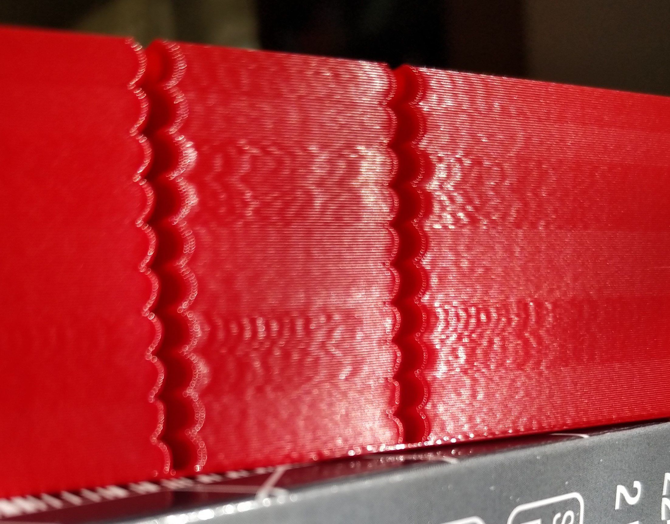
BlackStump
on 7 Oct 2019
All right, I finally managed to put together some code to combine the S-Curve acceleration across the moves. Updated instructions, basically all you need is
$ git fetch s-curve-exp
$ git checkout s-curve-exp/scurve-combined
The code will need some cleanups and optimizations, but it should be fine for testing. A few things are still missing though:
- Pressure Advance code was not updated for the new combine logic; so PA is disabled regardless of your settings in
printer.cfgor from the console. - Acceleration compensation is not integrated into this branch.
- Does not have any special handling of corners to 'smoothen' them; this is no different than AO=2 or my previous branches.
On the other hand, the code now:
- better handles arcs and curves;
- bed meshing should not be a problem.
I have plans to update PA code in the near future; though depending on the Kevin's progress on his smooth-PA branch this may be unnecessary. Let me know what you think about acceleration compensation.
What you can test: you can still print the test model with notches many have been printing so far, but I do not expect major differences there vs. scurve-jerk-limit branch. Printing more complex models would be interesting with different parameters (e.g. with different jerk settings, e.g. recommended max_jerk value and 2-3x of that). If you run into any issues with the updated firmware - please report them too. Especially if you get errors like 'Timer too close' - as the code is somewhat slower now. Please attach the logs and mention what HW you use in such cases.
dmbutyugin
on 19 Oct 2019
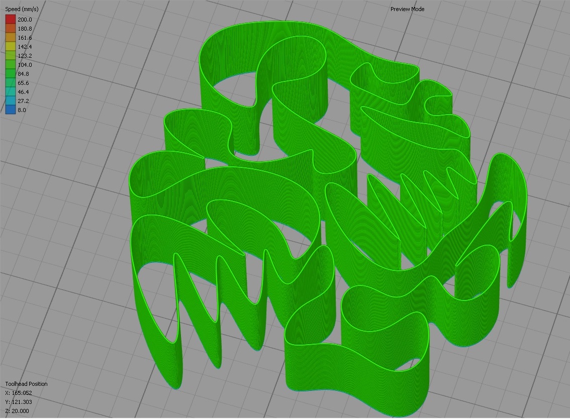
@dmbutyugin
got the 'Timer too close' error
Ender3 with OrangePI Zero Plus host and Geeetech 2560 MCU, TMC2100 drivers, 16 microsteps
it printed the normal notch test print fine so I tried a splinehell test
Spline Hell.zip
BlackStump
on 19 Oct 2019
OMG, what a test :) Thanks a lot! Looks like some optimizations will be required sooner rather than later. Klipper failed at the point when it queued 150 moves (so the latency bumped while processing them I guess), and there are even cases in this GCode when it will have to queue more than 300 moves.
dmbutyugin
on 19 Oct 2019
All right, a small update: as I was trying to optimize the code I did improve the performance by ~40%. But then I tried the previous scurve-jerk-limit branch. Quite unfortunately, even this one cannot keep up with this torture test from @BlackStump on my Raspberry PI 3. I did not test the master Klipper branch on this model [yet], but I suspect it will work, but will be operating close to the limits of this device. Anyway, this means that optimizing the Python code for combining the acceleration moves is a lost cause. BTW, the current scurve-combine branch can still print objects with lower resolution (and less moves/mm), for instance I did print this model, as well as 3DBenchy, just fine.
In the end, I am leaning towards rewriting the motion planning into C. Fortunately, some pre-work that can be re-used here has been already put into place by @KevinOConnor in his smooth PA branch. If it is used as a baseline, we can kill two birds with one stone: get fast motion planning and also get the PA working for the combined accelerations/decelerations.
Also, @BlackStump, would it be possible to turn your test model into a solid object? AFAICT, its geometry permits that. Then it will be super-easy to slice the model using the vase mode with whatever settings necessary. Right now Cura does not handle thin walls all that well and it has issues with slicing it. I was able to run your GCode with some small modifications on my printer, but that's less than ideal.
dmbutyugin
on 22 Oct 2019
@dmbutyugin
I did print the model using your scurve-accel-comp, and seem to print that ok.
splinehell stl was not one of my models however I should be able to model something along those lines in a solid, I shall try get the model done today.
cheers
BlackStump
on 22 Oct 2019
@BlackStump did scurve-accel-comp stop for brief periods during the print? Even if not, I suppose it was still close to its limits, and the reason my setup was slightly over the edge is because I use 3D printer with delta kinematics and 32 microstepping (160 msteps/mm on rails), which is computationally more expensive by itself. I did push my Python optimizations to the scrurve-combined branch - you can give them a try - but I honestly don't have high hopes for it to keep up with this test even on Cartesian printer.
dmbutyugin
on 23 Oct 2019
@dmbutyugin arh yes very true I did not test on my delta or corexy, so it did get a easy ride.
I suspect it did pause so it was on the limits yes. there are small blobs on the print consistent with brief pauses. It is a important test to get right for more complex geometry.
BlackStump
on 23 Oct 2019
@dmbutyugin
a solid splinehell, I checked that it slices fine in S3D
BlackStump
on 23 Oct 2019
Finally, C version of the move planning with combining can be tested. It is now faster than the previous Python-based implementation by an order of magnitude or two; should be even faster than the mainline. Of course, other parts like step generation have the same performance, still it now runs about the same as the mainline. You'll need to check out the new branch to test it:
$ git fetch s-curve-exp
$ git checkout s-curve-exp/scurve-c-combine
The code still does not support Pressure Advance (I'm waiting if there's going to be progress on smooth PA branch) and acceleration compensation - but should be fine otherwise.
A few other gotchas I've noticed:
- It looks like Octoprint cannot keep up on this 'spline hell' test too. Configure and use the virtual SD card on complex tests if you did not do that yet.
- The original GCode posted by @BlackStump still causes the toolhead to stop sometimes (so a bit of blobs appear) - but I believe this is a case of #1758 (comment) when uneven extrusion width between moves is above the threshold sometimes and it forces the toolhead to stop. The same test generated in the vase mode (thanks @BlackStump for solid object test!) does not show this behaviour - the test prints smoothly without toolhead stops and no blobs are produced. Though I did slice the test in vase mode in Cura, and the resulting GCode is smaller. Perhaps this has had some positive effect too - so if somebody can repeat the same vase test with S3D and report the results - it would be great!
As usual, please report any issues or strange behavior you encounter. Attach klippy.log and GCode you ran - this helps debugging a lot.
dmbutyugin
on 27 Oct 2019
disruption of z-axis steps when moving shallow from home position to G0 X10 Y10 Z5 F12000, z-axis speed and acceleration limits are not affected
ShohninDmitriy
on 27 Oct 2019
@ShohninDmitriy can you elaborate? What is printer kinematics? What exactly do you observe (skipped steps? Step rate too high?) Does it happen on scurve-jerk-limit branch too? Also, please attach klippy.log.
dmbutyugin
on 27 Oct 2019
My printer has core_xy kinematics, when processing the start script when going to print, there is a breakdown of steps on the z-axis
Start Gcode
[gcode_macro start_print]
gcode:G1 Z5 F120
M107
G90
M82
G92 E0
G1 X0 Y0 Z10 F12000
G1 X20 Y20 Z0.5
when the transition comes a breakdown of the steps the speed limit at 15mm/sec Z-axis fails, the rate is much higher
G1 E9 F100
G92 E0
G4 S5
G1 Z5
G1 X25 Y25 Z0.5 F12000
klippy.log
ShohninDmitriy
on 27 Oct 2019
on the previous build this was not the case and the start script worked well
ShohninDmitriy
on 27 Oct 2019
$ git checkout s-curve-exp/scurve-c-combined
mistake here and in documents, should be:
$ git checkout s-curve-exp/scurve-c-combine
ShohninDmitriy
on 28 Oct 2019
@ShohninDmitriy OK, thanks for reporting! Both issues (z-velocity limit) and branch name should be fixed now.
dmbutyugin
on 28 Oct 2019
@dmbutyugin. It's all right now
ShohninDmitriy
on 28 Oct 2019
The code still does not support Pressure Advance (I'm waiting if there's going to be progress on smooth PA branch)
FYI, yes, I am working on that. I'm in the process of reworking the changes so that they are in a shape to merge into the master branch. At a high-level, I plan to introduce a "trapezoid velocity queue" into the current data flow. Today, the speed and timing of each move speed is determined by the lookahead queue code, and then the kinematics code calls into the iterative solver to generate the step times for each g-code move. I plan to change this so that each stepper is associated with a trapezoid velocity queue during setup, the lookahead queue code will populate a trapezoid velocity queue, and then each stepper will be able to generate steps given a time range.
Unfortunately, I suspect the above will conflict with your work. Hopefully not horribly so though.
-Kevin
KevinOConnor
on 29 Oct 2019
Unfortunately, I suspect the above will conflict with your work. Hopefully not horribly so though.
I expect some conflicts, but I do not think it's going to be too bad. My changes, at high level, replace the existing Python move planner with C-based one. Still, currently Python code fetches finalized moves from the C move queue and pushes them into printer kinematics and extruder. After your changes are merged in, it will push the moves into the queues of all steppers - should be pretty straightforward. Maybe it will even be possible to eliminate this C (move planning queue) -> Python -> C (stepper queue) round-trip and just push moves to stepper queues directly (though there's some Python code dealing with enabling steppers, so this part might not be possible).
FYI, the trickiest part of the whole acceleration combining was to find the strategy to find splitting points for lazy queue flushes. With jerk limiting it is generally possible, counter to intuition, that if you add more moves to the queue, velocity at some junction points between the moves may decrease (though the _time_ required to cover the same part of the queue will decrease as well). So if you're not careful, you may end up in a predicament - the velocity committed at the previous queue flush may no longer be attainable with optimal planning as more moves are added to the queue. I think I finally nailed it though, and also added some reasonable safety fallback should the planing code still encounter such situation (because providing a strict mathematical proof that it will never happen is quite tricky, if at all possible for all cases).
- The original GCode posted by @BlackStump still causes the toolhead to stop sometimes (so a bit of blobs appear) - but I believe this is a case of #1758 (comment) when uneven extrusion width between moves is above the threshold sometimes and it forces the toolhead to stop.
BTW, I added some logging and confirmed it was this case indeed.
dmbutyugin
on 29 Oct 2019
Some further progress: I've added acceleration compensation support to the acceleration combining branch, as well as put some ideas how it can be tuned to the docs. You can expect some results like this:
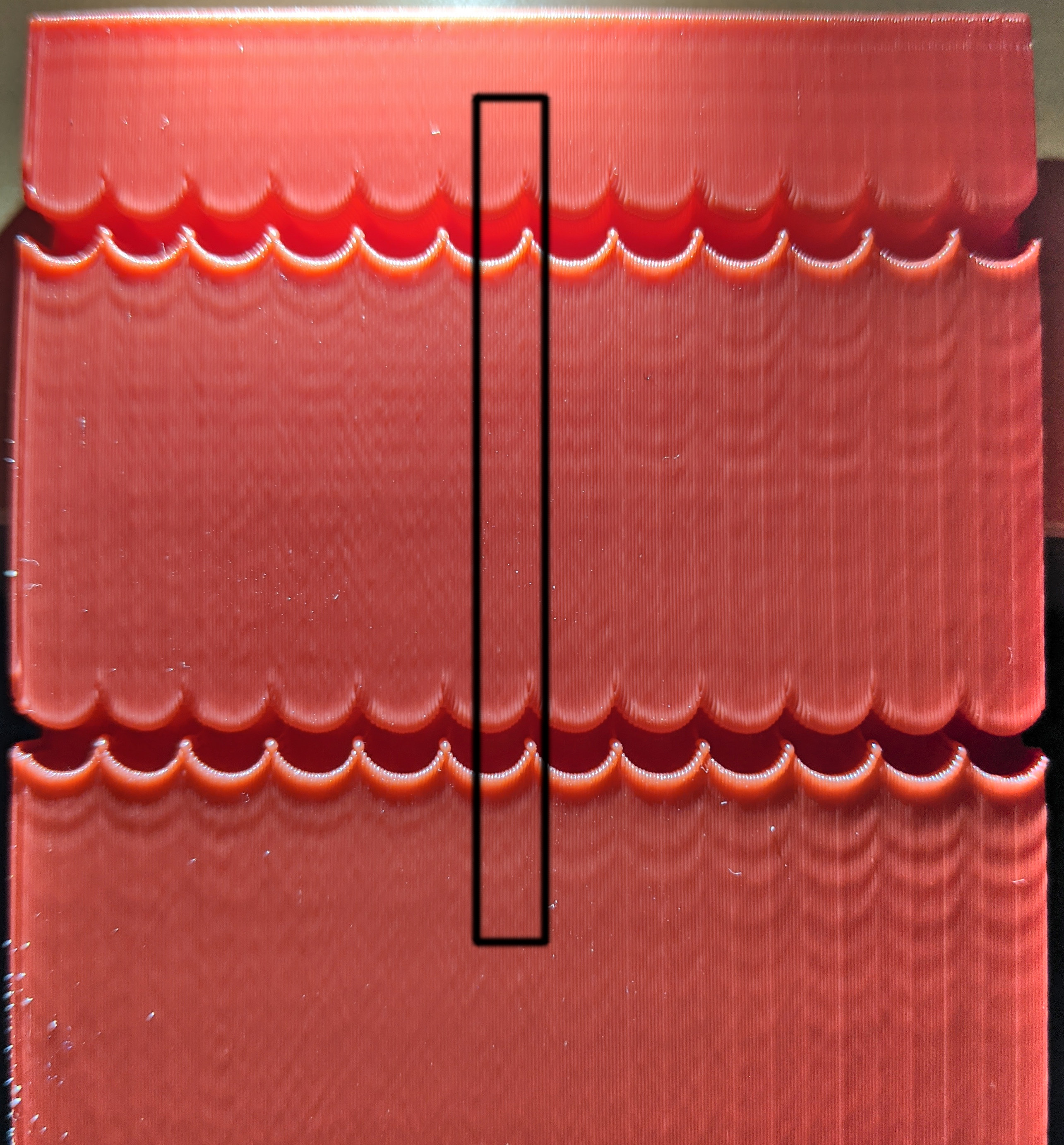
Printed on a delta at 100 mm/s, AO=6, accel 6000 mm/sec^2, accel_to_decel 4000 mm/sec^2, jerk = 1000000 mm/sec^3. The sweet spot is at around 0.000095 compensation with around 50-52 Hz ringing frequency.
You can even notice some differences on the spline test (though it is hard to make a clear picture of it):
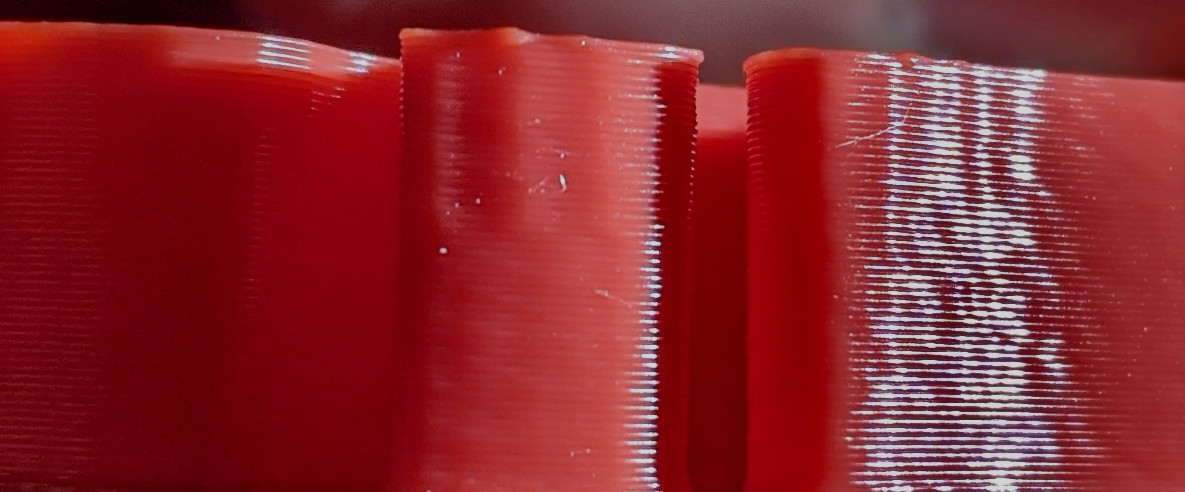
Top part printed without acceleration compensation, bottom part - with the tuned value. Without compensation and aggressive acceleration ringing can appear even on a smooth model around more 'spiky' parts.
dmbutyugin
on 1 Nov 2019
I have no more to contribute than saying that that looks absolutely amazing @dmbutyugin
lenne0815
on 1 Nov 2019
@dmbutyugin I have not had a chance to get near the printer for a week, so today had a little time.
btw I did not create the original splinehell stl and printing with your latest update it does have some brief pauses as you have determined as well but if I slice in S3D the solid stl, single perm it prints well, no noticeable pauses.
The gcode I posted was from the original splinehell stl which it seems has some modelling problems.
Print quality seems very good on the ender3 bed slinger with your C-combined.
I will include the spinehell solid stl sliced in S3D that prints smoothly.
SplineHell_vase_mode120.zip
sorry picture quality is not good, poor lighting
BlackStump
on 4 Nov 2019
FWIW, I've been printing with scurve-c-combine for some time now, and had no issues so far. The only feature that's really lacking is Pressure Advance. Problem is, it is quite a bit of work to adapt the existing PA planning code, and it is sort of a throwaway work. So I am thinking about going ahead and merging work-smoothpa-20190920 branch as-is, and then re-merge it again after it is merged into the mainline. I initially did not do this because I was worried that it may interact unpredictably with the changes I made, plus some folks reported scheduling regressions ('Timer too close' issues) on that branch, and I was not sure if it would be easy to tell issues related to my code and smoothpa apart. But now that scurve-c-combine has been there for a while, it either means that people did not encounter issues since the last fixes about a week ago, or nobody is really using it :) At any rate, it is probably worth doing.
dmbutyugin
on 5 Nov 2019
So I am thinking about going ahead and merging work-smoothpa-20190920 branch as-is
FYI, I've been actively working on the smoothpa code. I've just pushed up the latest changes (which is now on top of PR #2130). I'm hopeful this code is in a shape that can be merged into the master branch soon.
Separately, the work on the s-curves looks very interesting. Alas, I haven't had a chance to look at that code myself, and I'm probably a few weeks away from being able to.
-Kevin
KevinOConnor
on 5 Nov 2019
FYI, I've been actively working on the smoothpa code. I've just pushed up the latest changes (which is now on top of PR #2130). I'm hopeful this code is in a shape that can be merged into the master branch soon.
Good to know, I'll be merging in your changes then over the next few days.
Separately, the work on the s-curves looks very interesting. Alas, I haven't had a chance to look at that code myself, and I'm probably a few weeks away from being able to.
That's probably even better - I will have some time to clean up and refactor the code. In fact, your changes in PR #2130 provide a good reason to do that as a part of the merge.
dmbutyugin
on 6 Nov 2019
Good news, everyone! I completed a merge of smoothpa branch with the S-Curves code I've been working on. This closes the last gap in S-Curve implementation, so it can be used in all real-life scenarios. It is available in the branch scurve-c-combine-smoothpa:
$ git fetch s-curve-exp
$ git checkout s-curve-exp/scurve-c-combine-smoothpa
Note this is a new code for Pressure Advance, and you will have to re-tune it. Make sure to follow the discussion in PR #1997 for more details on how to do it. The PA should work the same way with S-Curve accel, but maybe some parameters, like pressure_advance_smooth_time, will have to be re-tuned for different values to work well with AO > 2.
I tested it on my printer and PA seems to be working. If you encounter some problems, let me or Kevin know. Basically, if you run into some problems with PA, repeat the test with AO=2 (or even under work-smoothpa-20190920 upstream branch), if it still persists - chances are high it's related to the original smooth PA code. If not - it's likely a problem of PA and S-Curve integration.
dmbutyugin
on 8 Nov 2019
@dmbutyugin I finished a splinehell test print with no problems to report PA seems to work and printing was smooth and quality was great.
BlackStump
on 8 Nov 2019
I started testing this last day or so... I have a bed slinger (Ender 3 with lots of upgrades) and getting around 200Hz for measured ringing frequency. Is that a reasonable number? I'm also getting 'rough' straight lines that is very apparent on top/bottom skin layers any ideas what is causing those kinds of artifacts?
 mattkenn4545
on 11 Nov 2019
mattkenn4545
on 11 Nov 2019
@mattkenn4545 unless you have a very, very rigid printer, 200 Hz does look suspiciously high for bed slinger. So far, nobody reported such high numbers.
I'm also getting 'rough' straight lines...
A picture, perhaps, would help diagnose the issue. As well as the settings you ended up with to get that. Just to be sure, you're testing scurve-c-combine-smoothpa branch, right?
dmbutyugin
on 11 Nov 2019
My printer is /very/ rigid so maybe it's OK?. I may have gone a bit over-board on my upgrades :) ie x/y linear rails and z-braces.
Yes I'm on your scurve-c-combine-smoothpa branch HEAD is b9ed6179aa0.
Pics coming as soon as the print finishes.
mattkenn4545
on 12 Nov 2019
Can you post some pics then once you have them together with klippy.log? The log has invaluable information, including your config.
dmbutyugin
on 12 Nov 2019
These are straight moves but there seems to be 'wiggle'
mattkenn4545
on 12 Nov 2019
This may not have anything to do with s-curve code etc... Looking at a calibration cube printed with no PA or tuning (ao=2) ie my starting point before any tweaks exhibits the same artifacts.
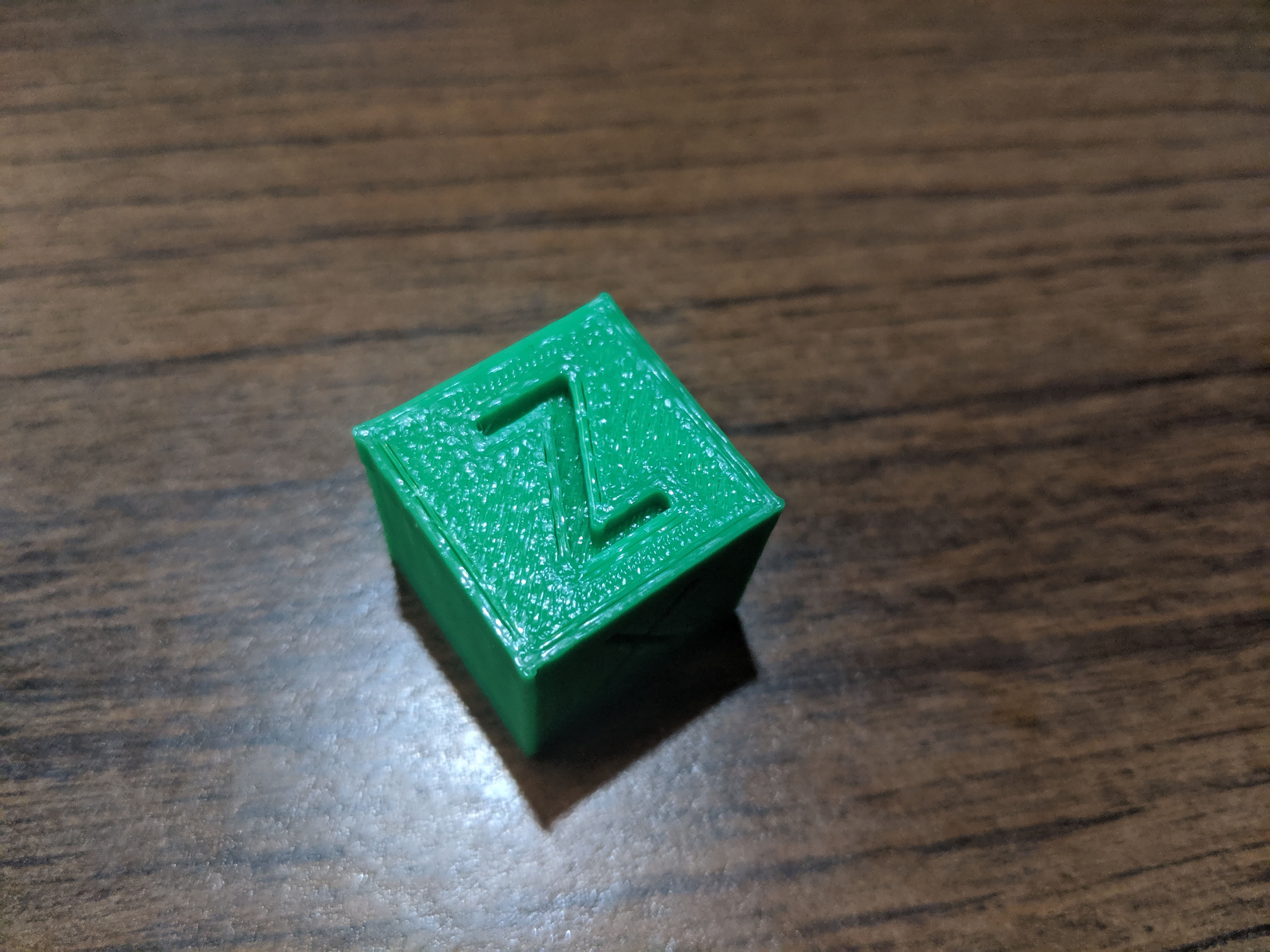
mattkenn4545
on 12 Nov 2019
What about the master Klipper branch? Does it have the same effect? Although AO=2 should generate the same movements as a master branch (well, as smoothpa branch to be more precise, because smoothpa branch does have slight differences in extruder kinematics vs. the current mainline even with PA disabled, if I am not mistaken), but worth double-checking.
But to be honest, this does not look like it can have anything to do with the printer kinematics - more like an extrusion problem of some sort.
dmbutyugin
on 12 Nov 2019
mattkenn4545
on 12 Nov 2019
Could this be related maybe https://github.com/KevinOConnor/klipper/commit/bdc7383e51ca37ec87c20fdbc14154ff1417a9dc
running test print now on kevin's master branch.... nope nm. Same artifacts
mattkenn4545
on 12 Nov 2019
Thanks.
Could this be related maybe bdc7383
Yes, it was not possible:
to reduce the chance that ... could cause an infinite loop
An infinite loop hangs the Klipper, for good. FWIW, I did not backport that commit into my branch because it conflicts with the code from smoothpa branch that I merged. On the other hand, this commit should have improved the situation, I did not encounter the infinite loop situations myself since.
dmbutyugin
on 12 Nov 2019
I think something is not quite right. Same gcode, left is scurve-c-combine-smoothpa right is work-resonance-20190928
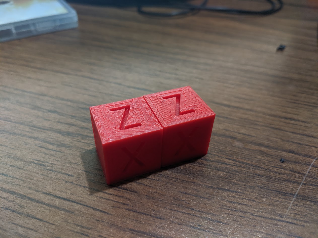
mattkenn4545
on 12 Nov 2019
running test print now on kevin's master branch.... nope nm. Same artifacts
@mattkenn4545 So you reported artefacts even without any changes, on master branch, right? This is pretty strange. The only suspicious part in the latest log that you posted, with supposedly better quality, is much lower max_accel_to_decel value - 500 vs 1500 previously. On such a small object this can drastically impact the max and the average velocity, and correspondingly the print time. Could it be insufficient cooling on too fast print that is provoked at higher velocities? Or problem with filament melting?
dmbutyugin
on 12 Nov 2019
Yes, the same artifacts on master. I've used many max_accel_to_decel values with similar end-results. max_accel_to_decel doesn't seem to have much of an effect with ao=6,
Another interesting thing (maybe) is the ringing freq test print shows ringing down the axis with no lessening of artifacts. In some of the other prints from others ringing decreases in intensity as the move continues. This doesn't seem to happen for my prints.
mattkenn4545
on 12 Nov 2019
I think I found the root issue. I had max_jerk set way too high and/or max_accel too high. If I put max_accel to ~1500 prints come out looking great on master and/or I set max_jerk to ~ 150000 and leave max_accel = 5000 with ao=6 they look good on scurve-c-combine-smoothpa
mattkenn4545
on 12 Nov 2019
I'm afraid that can't be the root cause, more like a way to mask another issue, be it mechanical, extrusion or cooling problem. I did print max_accel=6000 and max_jerk=1000000, so there is no reason to suspect these parameters alone can be the source of problems. I'd say 1500 accel isn't much for well-built rigid printer, even if it is a bed slinger. I'm not an expert on debugging such issues, but, TBH, it does look like either an extrusion or cooling problem, that is lessened by reducing the printing velocity (either by limiting accel or decreasing the jerk, which reduces the average velocity and increases the print time).
max_accel_to_decel doesn't seem to have much of an effect with ao=6
That's not fully true, but indeed, frequently jerk limit kicks in first before max_accel_to_decel. Though max_jerk must be set pretty low for that to happen (i.e. I would not consider max_jerk = 696000 from your previous tests a low value). In the end, if you set it to low value, it will certainly have an effect with AO > 2.
the ringing freq test print shows ringing down the axis with no lessening of artifacts.
That's pretty unnatural. Ringing (oscillations) must decay - that's just the laws of physics. So it's either that oscillations in your case have high Q-factor, or, a bit more likely, there is a source of vibrations in the printer that resonates with ringing: steppers vibrations (due to drivers), teeth of the pulleys on the belts, etc. How you can test this theory: try the ringing test reducing the velocity (say, by 50%), and the same test increasing it (also by 50%, if the printer permits). If you see ringing decaying at least it one of the cases - this would support this theory.
dmbutyugin
on 12 Nov 2019
I tried a calibration cube to see why it is a popular choice for people to use a a test print, sorry I don't see the attraction. First up because it is 20x20x20mm if you print it with PLA at any speed apart from very slow then it is heavy influence by print cooling.
Reason being layer times are quick even at slow print speeds so the printed PLA does not have time to loose much heat even with active cooling.
Even as a dimensional calibration print it is too small a sample to be on much use.
@dmbutyugin
I am getting random timer to close errors ie I printed the calibration cube fine then did a a normal test print and got the timer to close error.
I will try get you a log with the error.
BlackStump
on 13 Nov 2019
@dmbutyugin thanks for your pointers. I now have decaying oscillations in the ringing tests!
Turns out the issue appears to be 1) printer is extremely rigid 2) printer very solidly affixed to a very sturdy workspace (essentially on a concrete foundation). Was running on the assumption that getting everything as solid as possible would lead to best quality prints. Fix was to print some 'feet' that allow the printer to vibrate. Now getting decent quality prints with max_accell ~= 5000 and max_jerl = 350000 still tuning the other parameters but I think the mechanical issue is resolved.
mattkenn4545
on 13 Nov 2019
Your printer was literally shaking the foundations? Woah.
PLA or not, that's metal.
FeepingCreature
on 13 Nov 2019
@mattkenn4545 Interesting. Well, that's a good reminder than any printer needs at least some damping - otherwise the energy of spurious oscillations will have nowhere to dissipate. BTW, please post your parameters here after tuning for the reference, and what kind of quality you will have managed to achieve.
@BlackStump yes, please do post the logs of the failure and GCode that you were printing. I presume you use a virtual sd card?
dmbutyugin
on 13 Nov 2019
EDIT : I found where to start : docs for s-curve-combine+acceleration compensation
then for PA : discussion in PR #1997
aschor
on 15 Nov 2019
@aschor yes, that pretty much summarizes it. You can consider tuning acceleration compensation, TL;DR is:
- disable PA
- measure the ringing frequencies for X and Y axes
- tune max corner velocity (or just set it at low value or leave it at default)
- compute min_jerk_limit_time and max_jerk values
- set desired ACCEL and high JERK values
- tune ACCEL_COMPENSATION parameter
- tune (decrease) JERK value
- tune PA
What you can expect after tuning acceleration compensation: you will get max_jerk value higher than 'normal', so you'll get faster prints. Note that smooth pa branch generally requires PA re-tuning. Most of the folks reported they needed slightly higher PA values than on master branch, but it is not fully clear if this is an effect of smooth PA or S-Curve smoothing effect.
dmbutyugin
on 15 Nov 2019
@BlackStump BTW, I did run into the "timer too close" issue once lately, and it was on a fairly simple print, but at high velocity and accel. I have a logging to measure the timing of the new lookahead algorithm, and it wasn't slow at all - in range of 300-500 microseconds per queue flush. I suspect it could either be some regression in the smoothpa branch, or maybe some flush timing constants need to be adjusted - in the end, the new lookahead algorithm tends to keep more non-flushed moves in the queue than the previous one. There were also some fixes in the mainline branch lately, and I see that all conflicts with the smoothpa branch were resolved - so I'll sync my branch with the latest mainline, and maybe that will fix the timer scheduling issues.
dmbutyugin
on 16 Nov 2019
@dmbutyugin sorry I haven't got back to you but other parts of my life are taking all my time at the moment.
I am still keen to finish the testing and I am hoping that I will get time in a few days to do just that.
cheers
BlackStump
on 16 Nov 2019
Of course, that's no problem. Anyway, I synced my branch to the latest smoothpa branch, we'll see if it solves timer issues (if you ever encountered them).
dmbutyugin
on 17 Nov 2019
@mattkenn4545 Can you share, where did the tuning process lead you to? What kind of parameters did you end up with? (And ringing frequencies, after you solved the non-decaying ghosting issue) I understand you still had some quality issues, I wonder what they were.
dmbutyugin
on 17 Nov 2019
@dmbutyugin Are you saying your master branch was synced with the latest smoothpa branch or was it your scurve-c-combine-smoothpa branch?
 robschwieb
on 18 Nov 2019
robschwieb
on 18 Nov 2019
@robschwieb scurve-c-combine-smoothpa branch
dmbutyugin
on 18 Nov 2019
Hi @dmbutyugin - I can share the findings I have made with your branch on my direct drive converted Ender 3.
I measured ringing of 32.25 Hz with the initial settings. The relevant configuration settings I ended up with were:
[printer]
acceleration_order: 6
min_jerk_limit_time: 0.031
accel_compensation: 0.000024
square_corner_velocity: 5

[extruder]
pressure_advance: 0.0412
pressure_advance_smooth_time: 0.035
The S-Curve.md instructions were easy to follow and seem to have produced the correct values for my setup (please let me know if something looks very off-base).
My calibration cubes (100 mm/s perimeters, 3000 mm/s/s max_accel) came out quite nearly perfect - certainly the best I have ever been able to produce.
I'd be happy to provide any other information that could be helpful.
 fiferboy
on 18 Nov 2019
fiferboy
on 18 Nov 2019
@fiferboy that's good to hear! Did you also try to tune max_jerk setting? Well, the instructions provide an idea how to increase it from the default value (which would be ~60000 in your case). I'm asking because it is not in the config you posted. Otherwise, the values look reasonable, and I'd expect slightly lower ringing frequency (~30 Hz) on direct drive because of the larger moving mass.
dmbutyugin
on 18 Nov 2019
@dmbutyugin I left that value as the default so far. I will try increasing it this evening or tomorrow. I calculated it to be around 58000 with my values (which I wasn't sure if my numbers were correct, so thanks for confirming!)
fiferboy
on 18 Nov 2019
I printed a tuning tower to test max_jerk settings - starting it at 50000 and incrementing by 50000 every 5 mm. I think it would have been better for me to use a 10000 increment, because 50000 was nice a clear (only the faintest of ghosting) and 100000 was almost as good, but every level up increased ghosting fairly noticeably.
I settled on 75000 max_jerk for now and ended up re-tuning pressure_advance again since my corners were quite squished out.
My relevant settings are now:
[printer]
acceleration_order: 6
min_jerk_limit_time: 0.031
accel_compensation: 0.000024
square_corner_velocity: 5
max_jerk: 75000

[extruder]
pressure_advance: 0.124
pressure_advance_smooth_time: 0.035
I will post some photos of my test prints later tonight - let me know if there is anything in particular that would be useful to see. It will also be helpful for me to see if my prints are actually close to optimal or if my judgement is way off :)
fiferboy
on 19 Nov 2019
Thanks!
I think it would have been better for me to use a 10000 increment, because 50000 was nice a clear (only the faintest of ghosting) and 100000 was almost as good, but every level up increased ghosting fairly noticeably.
At high level, the idea is to determine a range where the best value is in. For some printers the good value could be around 100'000, for some - 300'000, maybe 500'000. It could take time to reach 300'000 with 10'000 increments. I should clarify that in the docs, that first one needs to establish the reasonably tight range of acceptable values (e.g. 50'000 - 100'000 in your case, maybe 200'000 - 300'000 in some other cases), and then run another tuning with increments of 10'000 - 20'000 to fine-tune the value within that range. Or maybe the increment should be just the percentage (10-20%) of the default max_jerk value = 0.6 * max_accel * min_jerk_limit_time.
@fiferboy I have a couple of further questions: did you get the same ringing frequency on both X and Y axes? And also, if you have time, could you try to disable accel_compensation (set to 0) and try some test print to see if there is a difference? Basically, does it realistically improve the print quality (reduce ringing)? Or if you have determined that during the tuning process already - could you just share your findings regarding acceleration compensation and ghosting on your printer?
dmbutyugin
on 19 Nov 2019
@dmbutyugin my ringing frequency was almost identical between X and Y - I have the 4 mm glass bed on the machine right now.
I just did a back-to-back print with accel_compensation enabled and disabled. In the photos left has it enabled and right is disabled. I honestly don't see much of a difference between the two of I'm being honest, but if I was forced to pick which one has the slightest edge I would say 'enabled'.
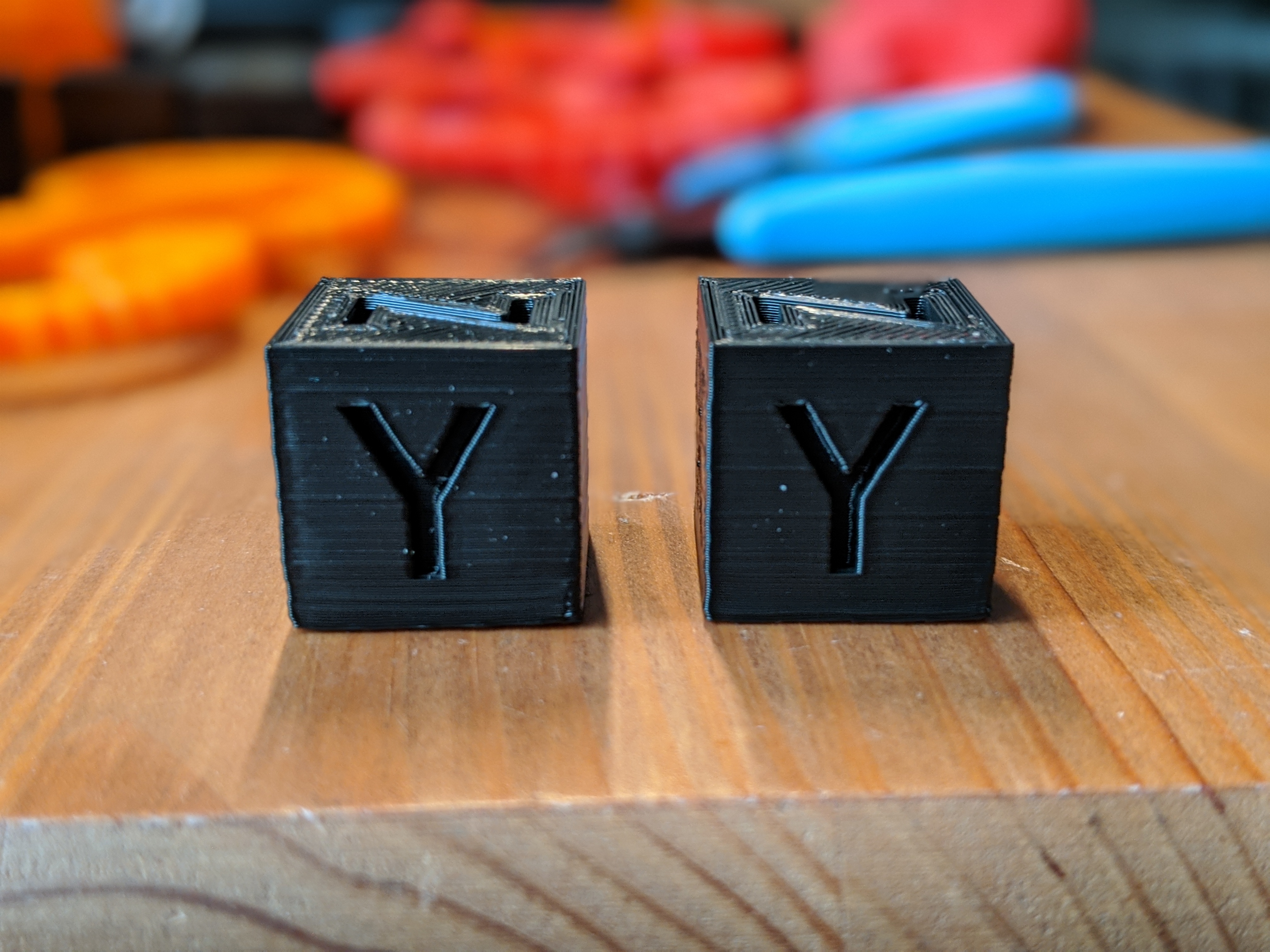
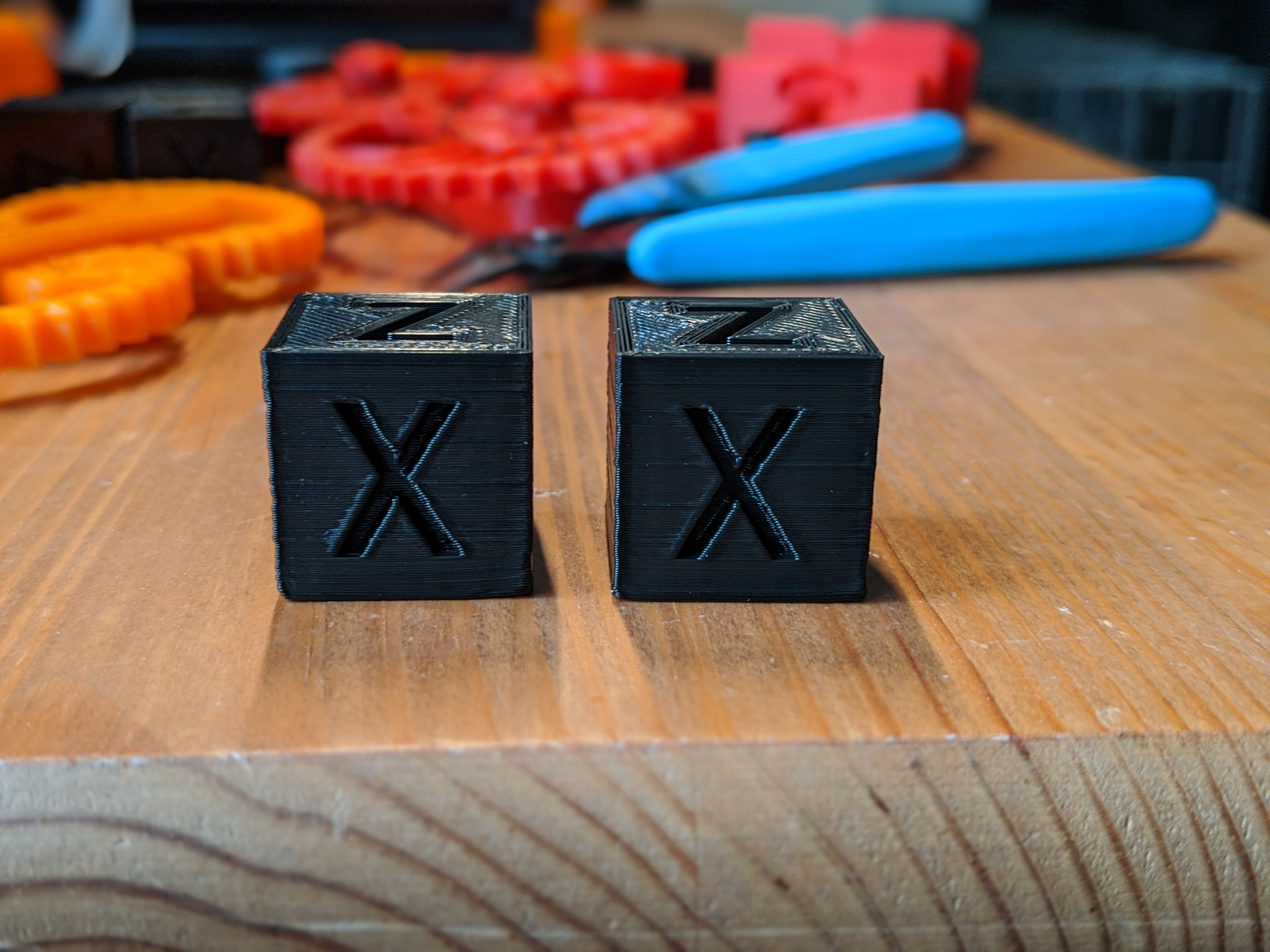
Upon close examination it looks like I could use a bit of e-step calibration as well :)
fiferboy
on 19 Nov 2019
Interesting, thanks. It appears that acceleration compensation did not help much in your case (judging by the fact that you weren't able to raise the max_jerk limit significantly from the default 58000, only by 30%). I wonder why.
100000 was almost as good, but every level up increased ghosting fairly noticeably.
Did you notice, by any chance, when you was increasing max jerk during this test, what was the periodicity of the ringing? Was it the same as before, when you was measuring the ringing frequency, or a different one? I basically wonder if perhaps the printer has several resonance frequencies, then acceleration compensation may not help. Or is it possible that you have some play in the printer (I see that the corner of the cube is not perfectly vertical, and some defects span multiple layers, so it shouldn't be an inconsistency of the filament diameter), or belt misalignment? Although, as others have pointed out, the 20x20 test cube is not the best test for fast printing - it is too small and can suffer from cooling issues. Although ringing issues can be tested on it.
Also, for acceleration compensation, did you just compute the value based on ringing frequency, or did you run the test to tune it? I mean this part of the instructions:
... Set very high max jerk parameter, e.g. SET_VELOCITY_LIMIT JERK=1000000. Print the test model increasing the acceleration compensation every 5 mm. It is a good idea to cover at least the range of values [0.5 / (2 π fmax)2, 1.5 / (2 π fmin)2]...
dmbutyugin
on 20 Nov 2019
I still have both the test prints I did earlier (the max_jerk test and the initial ringing test) and the ringing frequency is the same on both of them.
For acceleration compensation I did the calculation but didn't do a tuning tower for it.
My machine is definitely not 100% mechanically healthy, though I do have the belts tensioned nice and tight and they seem to be aligned properly. I think the carriages are seated properly with the eccentric nuts, but I would be quick to admit that both belts and carriages aren't dialed in as well as they probably could be. As you point out, the test prints have ample room for improvement in some areas, but I was pleased with the ringing/ghosting improvements your branch has made.
fiferboy
on 20 Nov 2019
I think it's OK then from mechanical perspective. Could you try this tuning tower for acceleration compensation if you have time? Since this feature is still experimental, there could be some effects that aren't accounted for in a simple formula to calculate the compensation coefficient, so maybe we will learn something from the tuned coefficient. And if it does not work well even after tuning (you won't see a noticeable ringing reduction with different compensation factors) - well, that's also an important piece of info, and you can roll back the config to your current one.
dmbutyugin
on 20 Nov 2019
@dmbutyugin I have printed a test tower with accel_compensation starting at 0.0000035 and increasing by 0.0000006 every 5mm.
The ghosting does increase at higher compensations by the faintest amount - I'm not sure if it is even visible in the photos. It looks like the Y axis shows up better in the pictures but the X axis is identical in appearance in person.
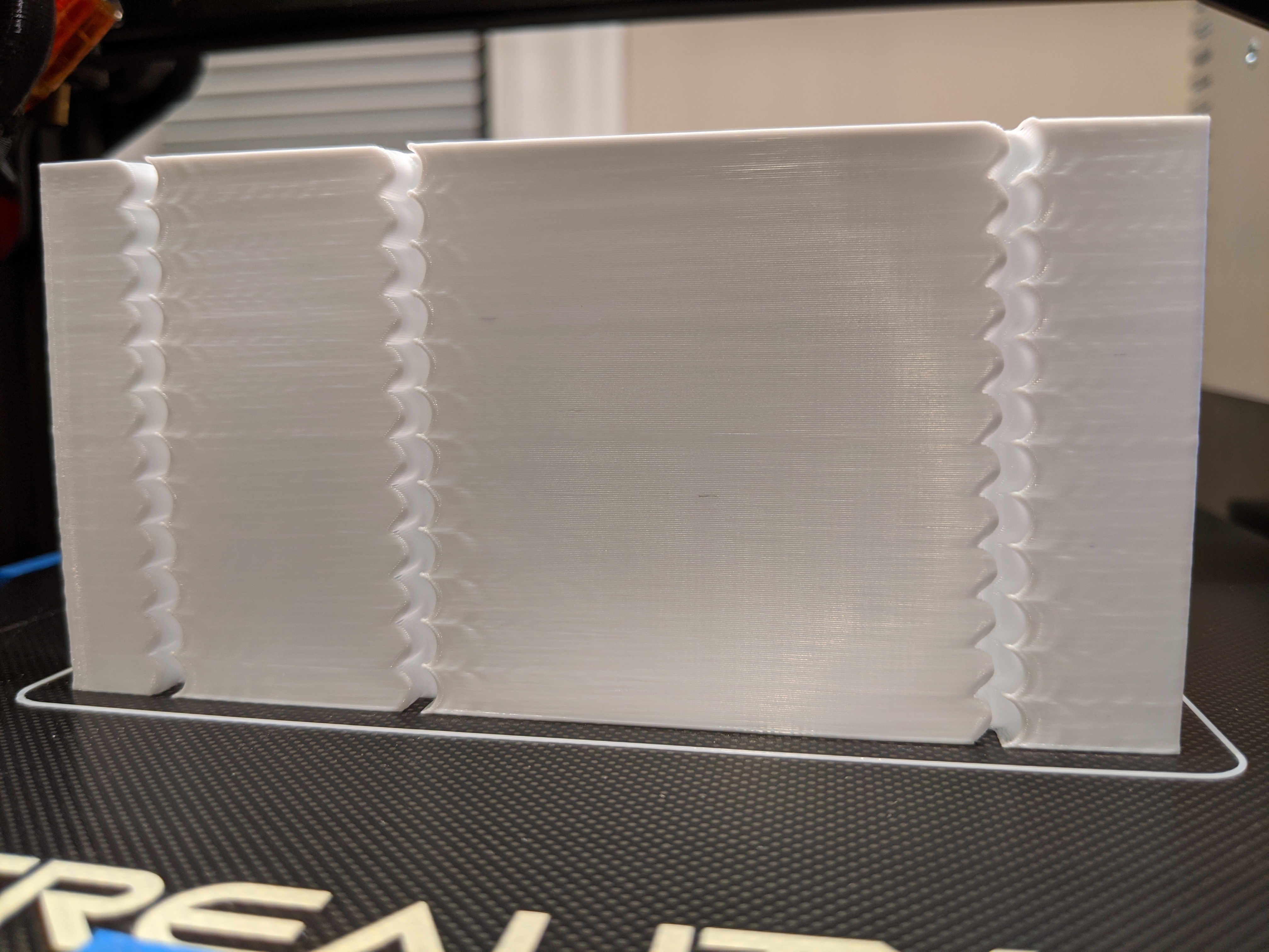
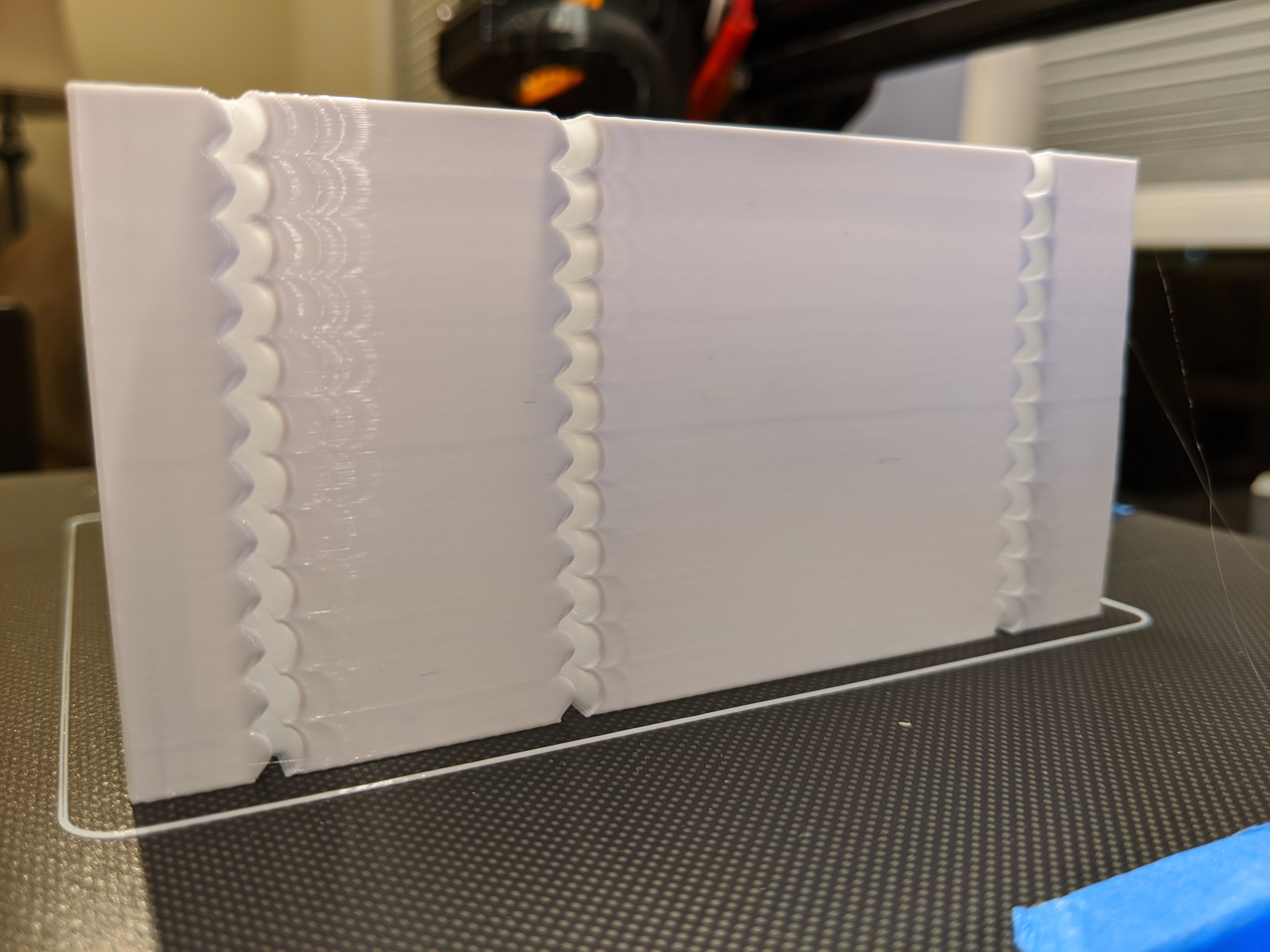
fiferboy
on 20 Nov 2019
Thanks a lot for your help! Can you also post the following parameters from your test print of the tower: max accel, max accel_to_decel and max jerk that you set up for this test?
dmbutyugin
on 20 Nov 2019
I used the ones from the documentation:
SET_VELOCITY_LIMIT ACCEL=5000 ACCEL_TO_DECEL=3000
SET_VELOCITY_LIMIT JERK=1000000
Sorry for nagging you, especially given that I cannot promise this can be helped :) But can you also post the max_accel from your config? The thing is, Klipper does not allow to set max_accel above the limit from printer.cfg, so even if you ran SET_VELOCITY_LIMIT ACCEL=5000 ACCEL_TO_DECEL=3000, you may have ended up with a lower accel than that because you're most likely had a smaller limit in your printer.cfg.
Otherwise, it _appears_ that you may want to set lower accel_compensation for now, something along 0.000008 perhaps.
dmbutyugin
on 20 Nov 2019
It's not a nag at all - my printer isn't doing anything important right now and I'm happy to help.
My max_accel is set to 3000, so I suppose that affected that last test a bit. I'll try out 0.000008 for my accel_compensation. Thanks for all your efforts!
fiferboy
on 20 Nov 2019
It looks like I had some slicer settings that may invalidate my numbers here - specifically Enable auto cooling in Prusa Slicer which limits speeds based on layer print times. I'm not sure if it would affect bigger objects like tuning towers but it is definitely affecting my calibration cubes.
I will try re-tuning over the next day or so and let you know if anything changes for my findings.
fiferboy
on 21 Nov 2019
It could have impacted the ringing frequencies measurements, so you can repeat those. Other measurements should be fine, they should not depend on the velocity (as long as Prusa Slicer does not limit acceleration in addition to velocity, which I hope it doesn't).
dmbutyugin
on 21 Nov 2019
Recalculated my ringing at 42.86 Hz for both axis and setting min_jerk_limit_time beautifully suppressed ringing in the subsequent test print. pressure_advance changed after this as well, which I have calibrated also.
I will try a test print with a calculated accel_compensation of 0.000013 before continuing tuning, but further tuning will likely not happen tonight.
fiferboy
on 21 Nov 2019
Hello @dmbutyugin , I updated to your scurve-c-combine-smoothpa branch, ran the test print, but I only manage to get one oscillation. I had to up the acceleration to 5000 for it to be distanced enough from the original notch. At 3000 acc and 20 v_square, it's still pretty close to the notch. At any rate, should I measure that to find my ringing freq?
Edit: Do I have to disable PA before running the test print?
Edit 2: I've disabled PA, ran the test print, which came out pretty much the same. I've then disabled minimum speed and I got the expected results. Now I'm off to calculating the ringing frequencies and report back!
 Angelol125
on 29 Nov 2019
Angelol125
on 29 Nov 2019
I'm now stuck at another step. Trying to find out the best square_corner_velocity, I send this
TUNING_TOWER COMMAND=SET_VELOCITY_LIMIT PARAMETER=SQUARE_CORNER_VELOCITY START=5 FACTOR=5 BAND=5
before initiating the print, but it doesn't make any changes in v_squared, terminal returns the unchanged contents of my printer.cfg.
Trying SET_VELOCITY_LIMIT SQUARE_CORNER_VELOCITY=5 also has the same effect.
Angelol125
on 29 Nov 2019
@Angelol125 Klipper does not allow you to set SQUARE_CORNER_VELOCITY higher than the value from printer.cfg. I reckon this is a safety feature. So you need to increase it in printer.cfg as well.
On a separate note, how did _minimum_ speed interfere with the testing? What was the value?
dmbutyugin
on 29 Nov 2019
I see.. Thank you for the reply and info.. I was about to post an update here. I had some help and jumped over this obstacle. But still I had to manually set it every 25 layers, tuning tower produced weird results. Using the tuning tower command above, and with v_sq=30 in printer.cfg, the first change went up to 17.5 and then 30. After that it tried to change, but it remained at 30 for the rest of the print. I'm printing the test print as we speak. After that, it's gonna be calculating jerk, acce_comp and then fine tuning jerk. I have calculated min and max jerk. I'll post an update with my findings in a bit.
Angelol125
on 29 Nov 2019
Sorry, I forgot to reply about the minimum speed question, hence the 2nd commend.
So, minimum speed time, at least in my case, had these results. I had set it the same as the outer wall speed (100mm/s), and it produced one single (almost 100% clearly) visible oscillation. After dialing it down to 10mm/s, the ringing became much more apparent. Now, after printing the test with 10mm/s min. speed, I reexamined the first ones by holding my phone with the flashlight on above it and between the walls, and saw another 2nd oscillation, a very faint one but another nonetheless. It's appears as a tiny surface imperfection that can only be seen when shining light directly from above, since it doesn't have that much difference in color like the first one does, or like the many oscillations where min. speed is 10mm/s. I don't know if that made sense. Maybe my wording is not the best, english is not my first language.
Edit: I forgot to ask one thing. When I try to tune acceleration compensation, should I go with acc_order:2 or 6? It's not clear to me if I should return to acc_order:6 after finding the ringing frequencies or if I should keep it for the rest of the tuning, for acc_comp, jerk etc..
Angelol125
on 29 Nov 2019
Using the tuning tower command above, and with v_sq=30 in printer.cfg, the first change went up to 17.5 and then 30.
TUNING_TOWER command has somewhat weird behaviour when BAND is active. The formula is value = start + factor * ((floor(z_height / band) + .5) * band. So if you set z_height = 0, you get value = start + factor * 0.5 * band, in your case 5 + 5 * 0.5 * 5 = 17.5. You probably want FACTOR=1 and then START=2.5.
When I try to tune acceleration compensation, should I go with acc_order:2 or 6?
Yes, apparently this is not covered in the docs. You should use acceleration order = 6 for that.
dmbutyugin
on 30 Nov 2019
Something I also forgot to mention before, with regards to minimum speed, is that I had minimum layer time set as 0. Don't know if it's relevant info, just throwing it in just in case. Also, I have measured my ringing frequency in X as 28.57Hz, 40Hz in Y, and I went with 34.3Hz as the average for my other calculations. With that, I got acceleration compensation=0.00002153039. Are these numbers ok?
You probably want FACTOR=1 and then START=2.5.
I will try another test print with these values and report back.
Angelol125
on 30 Nov 2019
Ok, it's pretty interesting. I ran the test print with no acceleration_compensation since I haven't tuned v_sq, and these are the results: It appears that I have either more under extrusion and less ringing or the other way around, more ringing and less under extrusion. On the lower half of the print, on the X axis, there is plenty of under extrusion which seems to fade as it goes from one notch to the next one. On the upper half, I get ringing which is more pronounced the higher it goes. There is still some small under extrusion throughout the whole height of the X axis face. On the Y side now, things are much milder. Just some tiny bits of under extrusion on the lower half and a bit of ringing on the upper half. In conclusion though, the trend remains the same. The more under extrusion there is, the less ringing, and vice versa. Also, something that is not that noticeable in the photos, is that on the X axis, in the 3rd quarter of the height (10-15mm) , the ringing appears to be half the width of what the ringing is on the last 5 (15-20mm) and also closer to the notch.
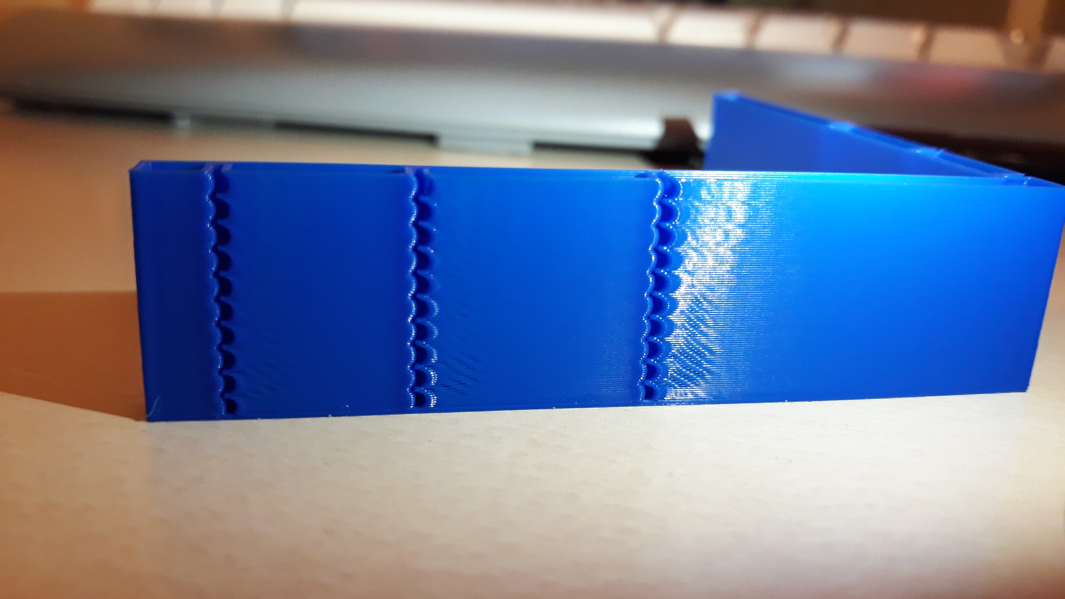
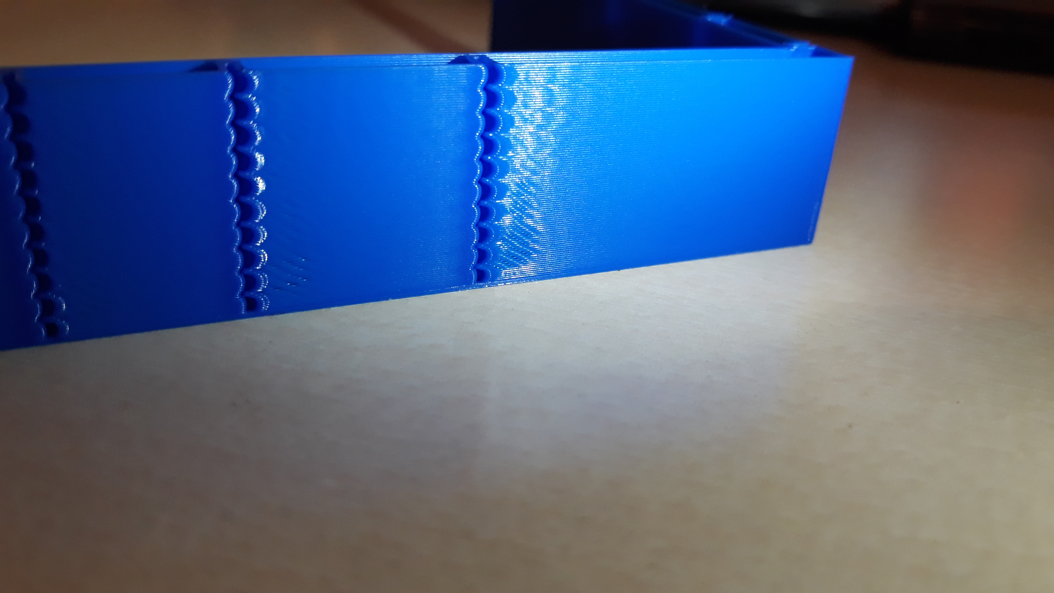
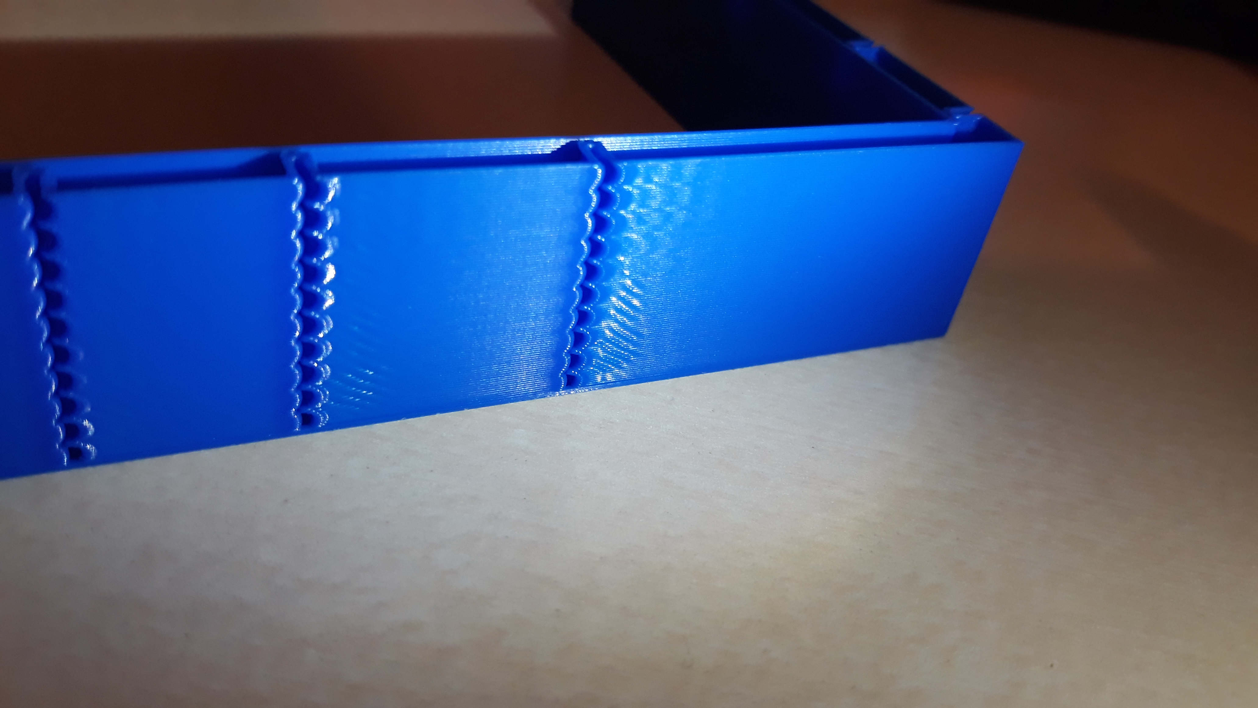
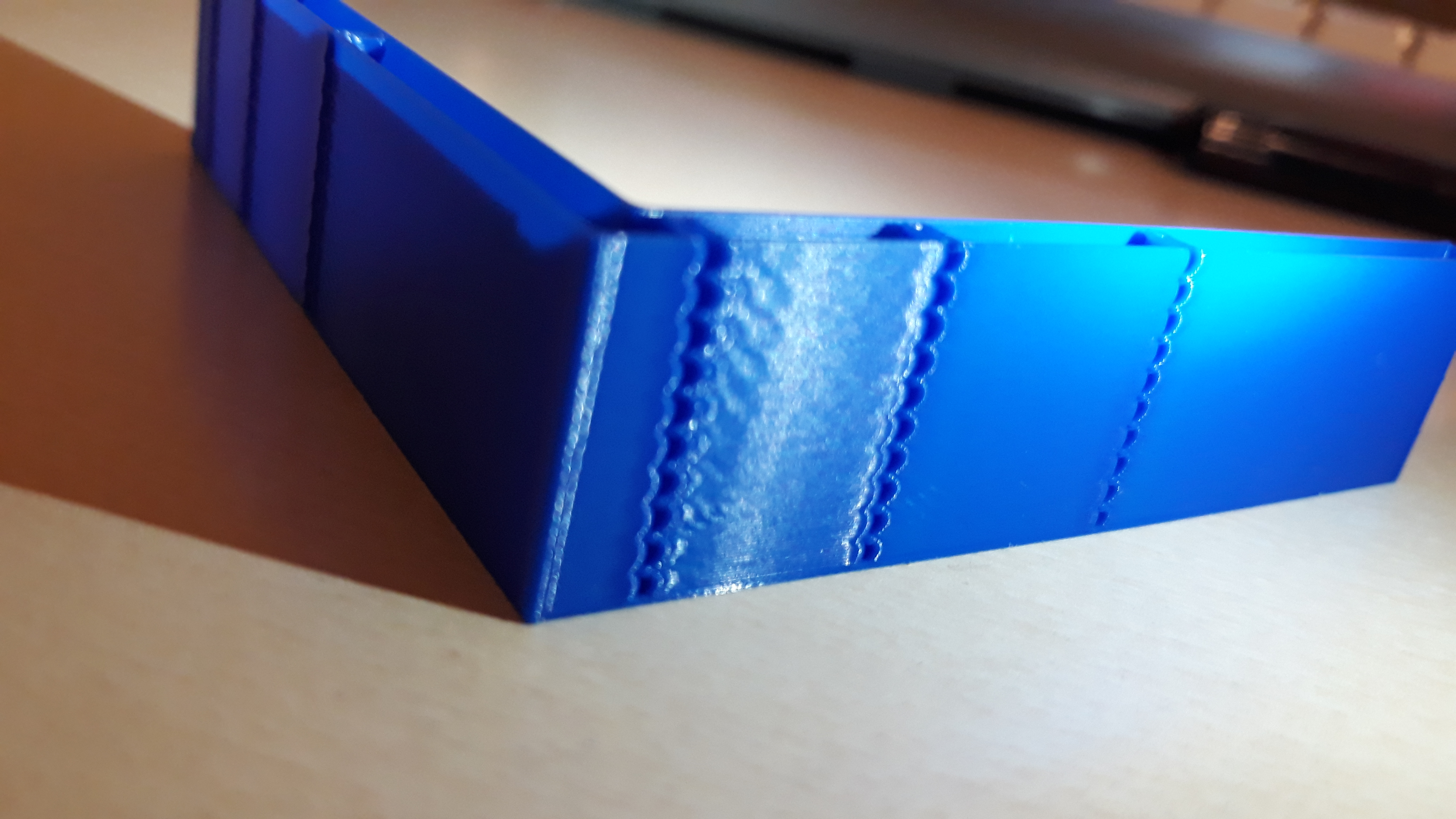
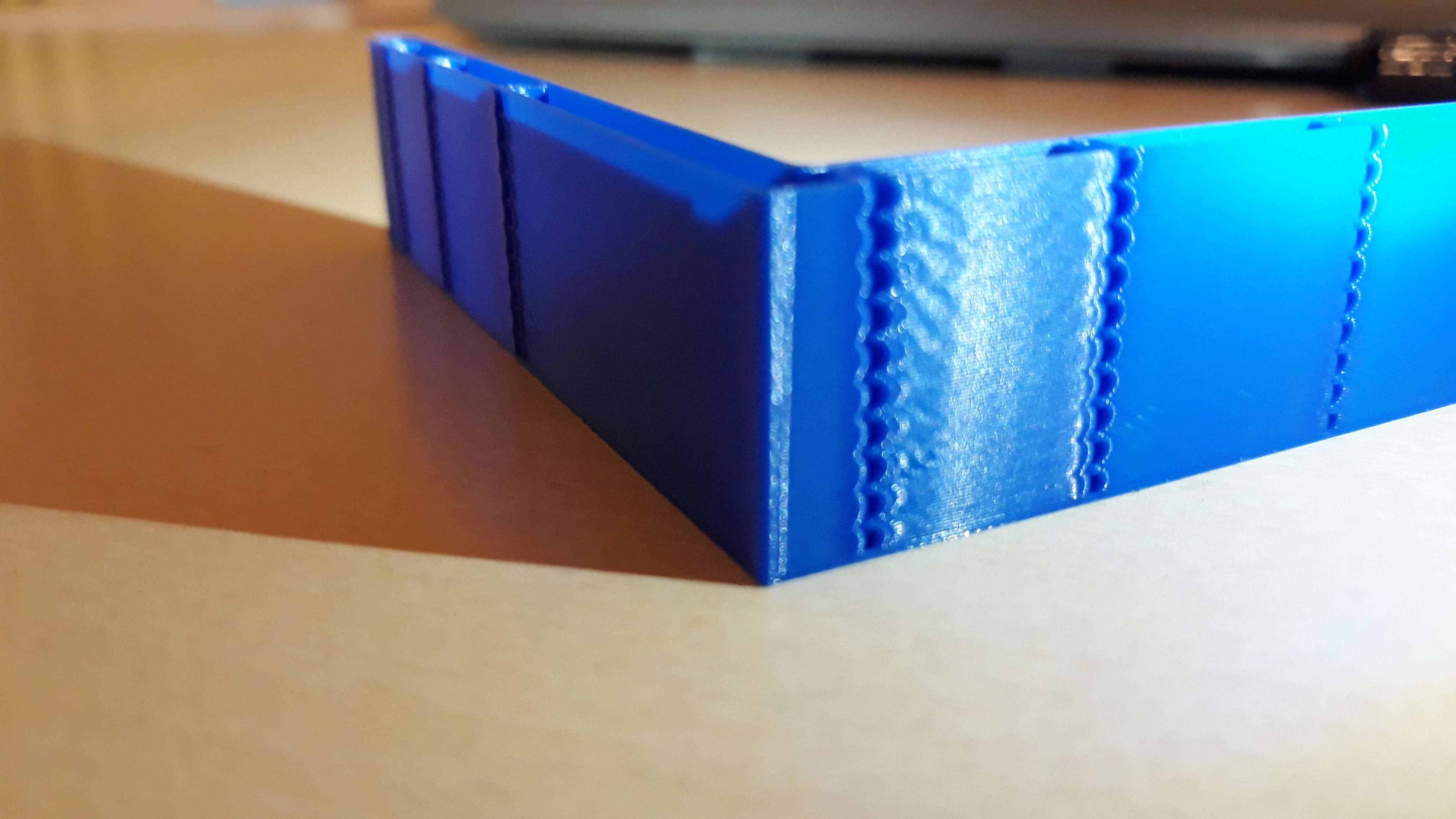
Angelol125
on 30 Nov 2019
BTW, following the discussion in #2030, I've updated the docs on S-Curve to discourage increasing default square_corner_velocity = 5 mm/s - so it no longer needs to be tuned.
@Angelol125 did you manage to resolve under-extrusion? Does the same thing happen if you print the same GCode on the master Klipper branch with the same max_accel parameter?
dmbutyugin
on 5 Dec 2019
Sorry for being absent the last days, I wish I could have replied much sooner, but unfortunately I couldn't. So, these are my new findings. I ended up with min_jerk_limit_time: 0.02915 and max_jerk: 61740, for my Fx=28.57Hz and Fy=40Hz resonance frequencies since my acceleration is set at 3000. Now, from my first tuning tower test about velocity_squared, I determined that my v_sq should be at 15. I then tried tuning acc_comp with TUNING_TOWER COMMAND=SET_VELOCITY_LIMIT PARAMETER=ACCEL_COMPENSATION START=0.000004 FACTOR=0.0000008 BAND=10, since I aimed for [0.000008,0.00048] in a 60mm test print. The results were pretty nice since most of the ringing was suppressed. I only noticed some tiny bits of underextrusion mostly on the X face. At that time, I was about to do 2 more tests, one for each bracket that didn't have underextrusion, and this is where I had stopped. I then saw your reply today, suggesting that we keep v_sq to the default 5, and I started an accel_comp test with the same TUNING_TOWER COMMAND=SET_VELOCITY_LIMIT PARAMETER=ACCEL_COMPENSATION START=0.000004 FACTOR=0.0000008 BAND=10 command, but with v_sq=5 instead of 15. It appears that I have more under extrusion when v_sq=5. I do have a question though, because I'm unsure if I have understood the procedure about further fine tuning accel_comp, 100% correctly. After having calculated my min_jerk_limit_time and max_jerk values, do I have to set SET_VELOCITY_LIMIT JERK=1000000 as stated in the docs before the tuning tower command, or do I use my calculated max_jerk value (the one that I have calculated from the formula in the docs)?
For a single ringing frequency the suggested max_jerk value is 6 · max_accel · ringing_frequency
Edit: Also, yes, I forgot to say that I managed to solve my underextrusion problem. I had max_jerk: 102900 which was from when I had acceleration: 5000. I entered the correct value (61740) for 3000 acceleration and the underextrusion went away.
Angelol125
on 5 Dec 2019
It turns out that running with PA disabled is what gave me this underextrusion. After running all these test prints, I also did a calibration cube, and it too came up with underextrusion. I reverted back to the master branch, fired up a test cube and it had the same underextrusion which disappeared when I re enabled PA mid print. Unfortunately, I had PA disabled for all my tests since switching to this experimental branch and this is probably why I chased all these underextrusion ghosts. I don't understand why though, shouldn't I tune accel_comp and all the rest values with PA disabled as the docs say?
Angelol125
on 5 Dec 2019
@Angelol125 In my opinion it is better to tune parameters to reduce ringing with PA disabled because otherwise it may interfere with the testing (i.e. extruder may not be able to keep up with PA during the tuning when acceleration is set too high); also it is possible that PA re-tuning will be necessary after jerk and acceleration compensation tuning. Sorry that you had to chase the unknown issues with underextrusion at first. Normally you only need to check ringing when doing acceleration compensation and jerk tuning. But if you do experience noticeable underextrusion, it may be better to enable PA during such testing (PA should not change the ringing pattern by itself anyways).
After having calculated my min_jerk_limit_time and max_jerk values, do I have to set SET_VELOCITY_LIMIT JERK=1000000 as stated in the docs...
Yes, you should set high jerk value as the docs suggest. You will decrease it after acceleration compensation tuning (as the docs suggest), although you will likely be able to use higher value for max_jerk than 0.6 · max_accel · ringing_frequency. Which also means that after you enable PA, you can also use higher value for max_jerk than 61740 without a risk of under-extrusion.
dmbutyugin
on 6 Dec 2019
@dmbutyugin No worries, I don't mind testing. In fact I love it, even if I do get strange results. At any rate, I can try to run further tests now that I have some time near the printer. Also, interestingly enough, just before I make this comment, I tried to run a test with SET_VELOCITY_LIMIT JERK=1000000 followed by a TUNING_TOWER COMMAND=SET_VELOCITY_LIMIT PARAMETER=ACCEL_COMPENSATION START=0.000004 FACTOR=0.0000008 BAND=10 to try and tune acc_comp, and I got:
MCU 'mcu' shutdown: No next step
This is generally indicative of an intermittent
communication failure between micro-controller and host.
Once the underlying issue is corrected, use the
"FIRMWARE_RESTART" command to reset the firmware, reload the
config, and restart the host software.
Printer is shutdown
Angelol125
on 6 Dec 2019
@dmbutyugin Hello again. I just managed to get past the MCU 'mcu' shutdown: No next steperror by sending the tuning tower command after some of the first layer was printed. I'll report back with my results soon.
Angelol125
on 7 Dec 2019
It appears I spoke too soon. First test failed due to poor adhesion and the second one, which I initiated the same way, failed with the same no next step type of error.
Edit: Looks like 3rd time is the charm. So far so good. I'll post the details in a few mins.
Angelol125
on 7 Dec 2019
BTW, have you synced to the latest branch recently? There were some fixes in the mainline that I also integrated into my branch a few days ago.
Otherwise, what kind of hardware are you running Klipper on? If nothing else helps, perhaps you can set lower max jerk or acceleration. Also, for me to be able to help, the full log of the failed attempt is needed.
dmbutyugin
on 8 Dec 2019
@dmbutyugin
BTW, have you synced to the latest branch recently? There were some fixes in the mainline that I also integrated into my branch a few days ago.
Yes, I synced to the latest commit since I switched back Kevin's master branch, in order to print check if the underextrusion problems would persist.
Otherwise, what kind of hardware are you running Klipper on? If nothing else helps, perhaps you can set lower max jerk or acceleration. Also, for me to be able to help, the full log of the failed attempt is needed.
Sorry for not disclosing this info earlier. I run Klipper on stock Ender 3 v1.1.4 non silent mainboard. Here is the log
It seems though, that I can get pass the error by sending the tuning tower command after the perimeters/walls of the first layers are printed. I did that, and the print completed successfully.
I am also back home now, so I can continue with the tests. I am in the step where I will further narrow down accel_comp and then proceed to tune jerk.
Angelol125
on 8 Dec 2019
OK, but the log you posted does not have an error. I meant the log from the case of MCU 'mcu' shutdown: No next step error. Also, do you have Raspberry 2 or 3?
dmbutyugin
on 9 Dec 2019
@dmbutyugin sorry, I forgot to add that I have a pi 3 B. This
MCU 'mcu' shutdown: No next step
This is generally indicative of an intermittent
communication failure between micro-controller and host.
Once the underlying issue is corrected, use the
"FIRMWARE_RESTART" command to reset the firmware, reload the
config, and restart the host software.
Printer is shutdown
is the only (repeated) response I get in the terminal when the test stops, just after priming the nozzle.
Angelol125
on 9 Dec 2019
Where could I find the log you need if it's not the terminal log? Is there any other log file I'm not aware of besides klippy.log?
Angelol125
on 9 Dec 2019
No, it's that one, /tmp/klippy.log. It's just that it did not have any errors. Could it be that you posted a log from a different run? Whenever you have a chance, could you restart klipper, run the sequence that causes this issue, copy the log from your raspberry pi and post it here? This way you would ensure that the log is the most recent one and should have a failure.
dmbutyugin
on 9 Dec 2019
Sure, give me a few minutes.
Angelol125
on 9 Dec 2019
Here is the log as requested.
Angelol125
on 9 Dec 2019
And another thing to clarify: you did not have these errors while you had PA disabled, did you? If you disable PA now, does it change anything?
dmbutyugin
on 9 Dec 2019
I've run all these tests the past few days with PA disabled, based on our previous discussion and how it's better to tune accel_comp, etc with PA disabled. TBH, till the last few days, I hadn't tried tuning accel_comp while using SET_VELOCITY_LIMIT JERK=1000000, till I solved the underextrusion problem I had by setting the correct jerk and then figuring out the correct tuning tower command with your help. Most of my tests were on vel_squared.
Angelol125
on 9 Dec 2019
Hi, I'm starting the calibration process, my printer is finally up and running. 1st question : while measuring the ringin, should I include both of the marked notches in the 'N' account ? I suppose so, but that is important. Maybe in the docs we should get the actual calculation of the example pictures ? (should we read 7 for N, 12.14mm for D and 100mm/s for V ? )
Question 2 : after computing min_jerk_limit_time, it is advised to set "SQUARE_CORNER_VELOCITY=1" before printing the test model to check if there is improvement.... but by doing that we are changing 2 parameters, we cannot see the offect of min_jerk_limit_time , can we ? Or don't I understand right ?
Should I print the second time with A0=6 too ? I guess so, as AO=2 is just for measuring frequencies.
I'll try a 2nd test print with AO=6, computed min_jerk_limit_time, velocity_corner=1 and increasing acceleration.
aschor
on 14 Dec 2019
Here are my first results, any comment / advice are welcome (same file used, printer prepared before print) :
upper print :
AO=6 ; velocity_corner=1; pressure_advance=0 ; min_jerk_limit_time=0.020794474 ;
bottom print :
AO=2 ; velocity_corner=20 ; pressure_advance=0 ; min_jerk_limit_time=unset
for both :
pressure_advance=0 ; speed=100mm/s ; acceleration going from 1000mm/s² to 7000mm/s² (+1000 every 5mm height)
on the bottom print as you can see, I get no ringing whatsoever so I'm wondering what acceleration to use to tune sqare_corner_velocity (next step in the tuning process). I guess 7K, the worse possible value at AO=2 (I suppose it's unwise to go higher acceleration ? does anyone do it ?)
And wondering also if corner_velocity should be tuned at A.O.=2 or A.O.=6 ? (the docs should be clearer on that point IMO)
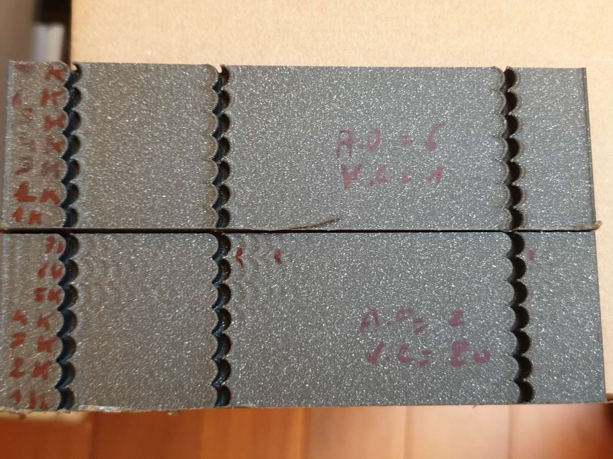
aschor
on 14 Dec 2019
Thanks for giving it a try. BTW, I would suggest to use scurve-c-combine-smoothpa branch - it has pressure advance support, and has many more updates from the master branch. I should probably delete the old branches.
To answer your questions:
1st question : while measuring the ringin, should I include both of the marked notches in the 'N' account ? I suppose so, but that is important. Maybe in the docs we should get the actual calculation of the example pictures ? (should we read 7 for N, 12.14mm for D and 100mm/s for V ? )
N=6 in that example, so you need to measure the number of periods. I should update the docs, it is a good idea to include the example of the computations.
Question 2 : after computing min_jerk_limit_time, it is advised to set "SQUARE_CORNER_VELOCITY=1" before printing the test model to check if there is improvement.... but by doing that we are changing 2 parameters, we cannot see the offect of min_jerk_limit_time , can we ? Or don't I understand right ?
Please check out the docs in the newer branch. After some discussion with Kevin in his other pull request he suggested that square corner velocity should not be tuned - not to the values higher than the default 5 mm/sec. So I removed all suggestions about tuning square corner velocity from the docs - please use the default value of 5 mm/sec, or lower if needed. You can choose to increase it, but that's at your own risk.
But yes, second time you should print a test with ao=6 or 4.
on the bottom print as you can see, I get no ringing whatsoever so I'm wondering what acceleration to use to tune sqare_corner_velocity (next step in the tuning process).
You probably meant the top print (so=6), didn't you? But as I mentioned you don't need to time square corner velocity now. Separately, it may be better to write in the docs more explicitly about the acceleration. In the beginning I say that acceleration does not need to be tuned - you only may need to increase it during ringing frequencies measurements, you can restore your usual value after that. You can, in theory, somewhat increase it if you are fine with the quality and don't expect problems like steppers skipping, layer shifts, etc. Hope that helps.
BTW, what kind of printer do you have, which kinematics, and what are the ringing frequencies that you've measured? Do you plan to test and tune acceleration compensation?
dmbutyugin
on 14 Dec 2019
@dmbutyugin yessss, I'm the right branch, but looking at the wrong docs, this explains that ... thanks for the right link !
looking at the docs, I think you should keep the velocity_corner JUST to get higher resonance (in my case it helps to see the ringing, at 7000mm/s² ! )
Yep, meant the top print ^^.
So with that new info (for me), I get 35hz and 37.1hz (I had previously 46.6 and 49.5 with one notch accounted but shouldn't have been)
I have no "usual" acceleration value, the printer is new. Only pressure advance will tell me what max accel I should not go past, I suppose. before smooth PA, I had tried and freaked out when I heard the extruder rattling with P.A. >1 and accel=3000 🗡
Yes, I plan to test and tune acceleration compensation, I hope that I'll see something :) (I have blobby corners for now)
I have built an hypercube evolution ( +- ngen), so coreXY with bowden. I have done a strong enclosure because the printer was too wobbly when first built (and because I want to print ABS). Now it is very rigid ... :) here it is :
(I know, it's a little raw ... but I don't plan to expose it in a museum ^^)
aschor
on 14 Dec 2019
I have no "usual" acceleration value, the printer is new. Only pressure advance will tell me what max accel I should not go past, I suppose.
Fair enough, my point is that ringing should not be a deciding factor at this point.
I have built an hypercube evolution ( +- ngen), so coreXY with bowden.
Oh, that's interesting. Could you also print the test model rotated 45 degrees and measure the ringing frequencies, as per docs? I think nobody with a corexy reported such results yet. Still, it would be very interesting to get them.
So with that new info (for me), I get 35hz and 37.1hz (I had previously 46.6 and 49.5 with one notch accounted but shouldn't have been)
Well, that's more to the point that this feature does not require very precise tuning (unlike acceleration compensation): you got very decent results even with the parameters a bit off.
dmbutyugin
on 15 Dec 2019
@dmbutyugin model printed at 45°, and ringing measured at 39.2Hz and 41.9 Hz. Strange, but one side is more ringing than the other one. Maybe a belt tension difference ? (I have one enclosure side - where the ringing is less visible, much lighter than the other -not the same material-, might also be interfering)
aschor
on 16 Dec 2019
Hey @dmbutyugin, I saw your conversation with @aschor today and that made me wonder and made me have second thoughts on whether I had calculated my ringing frequency the right way. I reexamined the first test that I calculated my ringing frequencies from, and I also printed a new one. Turns out I had my X side frequency wrong because I ignored one oscillation. Now, examining both in the first print and today's one, I got 40Hz for both my axes. Recalculated min_jerk_limit_time, max_jerk and accel_comp according to my new frequeny as follows:
min_jerk_limit_time: 0.025
max_jerk: 168000
accel_compensation: 0.00001583143
I'm printing a test for pressure advance now. Should I calculate my PA from this, or should I ignore it and tune max_jerk before tuning PA? I'm asking since I cannot understand for sure if I should tune max_jerk further since I have the same ringing frequency on both axes or not, or in other words, should I follow the further fine tuning in the docs or not since I have a single ringing frequency?
Edit: Also, I forgot to ask. Should I further tune accel_comp since I have the a single ringing frequency?
Angelol125
on 16 Dec 2019
Hummm that's impressive....
actual max_jerk without specifying it in the config : 108201.820633
computed max_jerk (5000mm/s) : 108201.8208
that's a close match !
reading the tuning process, the order is odd, I would reorder it :
- fine tuning as optional, but before pressure advance
- at the end of fine tuning, don't say "tuning process is now complete" because it is not : PA has to be tuned after it.
printing a accel_compensation tuning tower atm :) ................and I got a "Recv: // MCU 'mcu' shutdown: No next step". ... I must redo that one . EDIT : no, it did print ... but I failed the tuning steps ... redoing it next ...
aschor
on 17 Dec 2019
@Angelol125 you could still tune accel_comp: the suggested value comes from the approximation using harmonic oscillator, so you may find a better value through tuning, though I expect that the 'perfect' value should still be close to the value from the formula.
....and I got a "Recv: // MCU 'mcu' shutdown: No next step"
@aschor Can you post klippy.log when the failure occurs? You're probably running into the same issue as @Angelol125 did. My current suspicion is that iterative solver can hang during the tuning, e.g. due to some numeric instability. I have this suspicion because the previously posted logs did not suggest any performance issues with the new C-based lookahead algorithm, and I have currently no evidence to suspect that it can hang indefinitely. In fact, there were some fixes in iterative solver in the mainline lately, e.g. 4cbbe18. Unfortunately, I cannot merge this change, or all the changes from the mainline, into my branch from GitHub UI since there were some conflicting changes. So this will, unfortunately, have to wait until around after Christmas when I'll be able to get to it and properly merge the changes from the mainline.
Separately, can you folks reproduce the failure by running this command on your Raspberry Pi:
~/klippy-env/bin/python ~/klipper/klippy/klippy.py ~/printer.cfg -d ~/klipper/out/klipper.dict -i /path/to/troublesome.gcode -o /dev/null
? Or does this command finishes successfully without any issues? I mean, if you try the problematic GCode exactly the same way as when you get Recv: // MCU 'mcu' shutdown: No next step errors, possibly by incorporating the tuning tower command into gcode (as the command above is not interactive).
dmbutyugin
on 18 Dec 2019
@dmbutyugin I don't have the log anymore, sorry. But I think that's not an issue, because thinking of it, none of my prints were interrupted, and I DID press the reset button just before a benchy, because of wrong slicing parameters.
edit : I had not understood how to use the tuning tower. That is what's missleading (the band thing and the formula attached are odd, but that 's another story)
edit2 : STILL, there is an issue in the precision required :
Send: TUNING_TOWER COMMAND=SET_VELOCITY_LIMIT PARAMETER=ACCEL_COMPENSATION START=0.000007 FACTOR=0.00000067 BAND=3
Recv: // Starting tuning test (start=0.000007 factor=0.000001)
the factor of the tuning tower is not (at all) what we enter
Doing it whith slicer's integrated macro for now :
{if layer_z == 3}SET_VELOCITY_LIMIT ACCEL_COMPENSATION=0.000010015{endif}
{if layer_z == 6}SET_VELOCITY_LIMIT ACCEL_COMPENSATION=0.000012025{endif}
{if layer_z == 9}SET_VELOCITY_LIMIT ACCEL_COMPENSATION=0.000014035{endif}
...etc
aschor
on 18 Dec 2019
@dmbutyugin funny enough, I had the mcu_shutdown again with a new accel_comp gcode test. It happens AFTER the sd printing just finishes. That is strange oO.
klippy_mcu_shutdown.log
and if you want the gcode :
__tun__accel_comp.gcode.txt
I'll redo the print with your command, as I already had incorporated the set_velocity_limit commands (no tuning_tower command)
Anyways, here are the results of the test print (P.A. disabled after the print had started) :
(values of accel_comp tested . 0.0000070 ,0.0000100 ,0.0000120 ,0.0000140 ,0.0000160 ,0.0000181 ,0.0000201 ,0.0000221 ,0.0000241 ,0.0000261 ,0.0000281 ,0.0000301 ,0.0000321 )
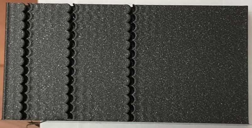
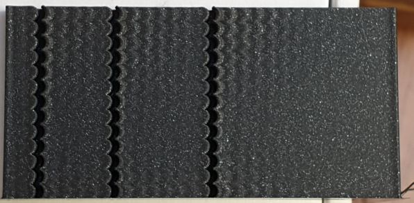
So on X axe, OK values are (for 5000 mm/s² and 5mm/s corener_velocity) :
0.0000140 , 0.0000160 , 0.0000181
and on Y axe, OK values are :
0.0000181 , 0.00002 and 0.000022
so my goto value will be 0.0000181 (for a theoretical value of 0.0000191128 )
aschor
on 18 Dec 2019
@dmbutyugin with your command, I get a lot of this, stopped it for now :
ERROR:root:lazy = 1, qsize = 7, flush_count = 4, flush_time = 101
ERROR:root:lazy = 1, qsize = 6, flush_count = 3, flush_time = 80
ERROR:root:lazy = 1, qsize = 6, flush_count = 3, flush_time = 73
ERROR:root:lazy = 1, qsize = 8, flush_count = 5, flush_time = 114
ERROR:root:lazy = 1, qsize = 7, flush_count = 4, flush_time = 99
ERROR:root:lazy = 1, qsize = 7, flush_count = 4, flush_time = 96
and it does not print anything, but I see some "set_velocity_limit" results inbetween ... oO
aschor
on 18 Dec 2019
did reprint a accel_comp test print at 3000mm/s, and again got a mcu_shutdown at the end of the print from virtual sdcard. That is really disturbing, never got that before (setting acceleration compensation > 0)
it like changing the acceleration_compensation parameter leads to that mcu_shutdown after a virtual sd print ( but what's the link ??)
aschor
on 18 Dec 2019
@dmbutyugin with your command, I get a lot of this, stopped it for now :
ERROR:root:lazy = 1, qsize = 7, flush_count = 4, flush_time = 101
ERROR:root:lazy = 1, qsize = 6, flush_count = 3, flush_time = 80
ERROR:root:lazy = 1, qsize = 6, flush_count = 3, flush_time = 73
ERROR:root:lazy = 1, qsize = 8, flush_count = 5, flush_time = 114
ERROR:root:lazy = 1, qsize = 7, flush_count = 4, flush_time = 99
ERROR:root:lazy = 1, qsize = 7, flush_count = 4, flush_time = 96
and it does not print anything, but I see some "set_velocity_limit" results inbetween ... oO
You don't need to worry about the messages. And this is a "dry-run" mode, so it does not print anything, but it still executes most of the code and generates stepper commands and stuff. So you just need to run and wait if it finished or not. I agree this error is disturbing. Do you also get it during the normal printing with accel compensation? I think another possibility is some flush timing issues when transitioning between normal and special print states (like homing).
dmbutyugin
on 18 Dec 2019
edit : I had not understood how to use the tuning tower. That is what's missleading (the band thing and the formula attached are odd, but that 's another story)
It's just that the behavior of BAND parameter is somewhat strange, from my POV. But I cannot go ahead and change it in my branch.
edit2 : STILL, there is an issue in the precision required :
Send: TUNING_TOWER COMMAND=SET_VELOCITY_LIMIT PARAMETER=ACCEL_COMPENSATION START=0.000007 FACTOR=0.00000067 BAND=3
Recv: // Starting tuning test (start=0.000007 factor=0.000001)
the factor of the tuning tower is not (at all) what we enter
Actually, this is simply a problem of displaying the result: TUNING_TOWER prints it's parameters with a certain precision, and it just rounds 0.00000067 to 0.000001 only for display. If you print the test, the actual parameters should be OK (and the output from SET_VELOCITY_LIMIT should confirm that).
dmbutyugin
on 18 Dec 2019
You don't need to worry about the messages. And this is a "dry-run" mode, so it does not print anything, but it still executes most of the code and generates stepper commands and stuff. So you just need to run and wait if it finished or not. I agree this error is disturbing.
Yes, it finishes just fine, if we forget about the error:roor:lazy ; no mcu_shutdown, or anything else
Do you also get it during the normal printing with accel compensation? I think another possibility is some flush timing issues when transitioning between normal and special print states (like homing).
no, I don't get the "error:roor:lazy" (on octoprint terminal) during normal printing (with or without accel compensation).
I'll print "normal" files tomorrow, with acceleration compensation, but without using "set_velocity_limit accel_compensation" command, and see if they finish or if it's pure coïncidence .
aschor
on 18 Dec 2019
@Angelol125 you could still tune accel_comp: the suggested value comes from the approximation using harmonic oscillator, so you may find a better value through tuning, though I expect that the 'perfect' value should still be close to the value from the formula.
@dmbutyugin Great, seems like my fine tuning hopefully comes to an end. Also, thank you again for your help. I have a couple more questions though. First, should I further fine tune max_jerk as well, or it requires no further tuning because I got a single resonance frequency? I'm asking, not only because I'm not sure from reading the docs if its mandatory or not, but also because I noticed that, even though I had acceleration: 7000 in printer.cfg, a calibration cube still took something close to 13-14 minutes to print. Shouldn't that be lower since that was similar to the time it took to print it with 2000-3000 acceleration give or take, before switching to this branch? Also, concerning to accel_compensation, I'll try to fine tune it a bit more after I sort a little problem that I have, which brings me to, well, my little problem. I've calculated my PA to 0.0865 down from 0.1 that I had, before switching to this branch. I still get some bits of under extrusion. Now this underextrusion somewhat went away, but not completely, after I upped my printing temps from 205 to 225 (manufacturer's max suggested temp for eSun PLA+). Could this under extrusion be from a not yet perfectly tuned max_jerk/accel_compensation/PA or simply a limitation of my stock hotend? The print with the underextrusion is a benchy that printed in 48 mins, 150 mm/s outer walls, 300 mm/s infill and inner walls, 5 or 10% infill (don't remember), 150 mm/s minimum speed, 0 s minimum layer time, Acceleration: 7000
Lastly, I tried your command and this is the output I got:
~/klippy-env/bin/python ~/klipper/klippy/klippy.py ~/printer.cfg -
d ~/klipper/out/klipper.dict -i /home/pi/.octoprint/uploads/60mm.gcode -o /dev/n
ull
INFO:root:Starting Klippy...
INFO:root:Start printer at Wed Dec 18 22:26:44 2019 (1576708004.2 370.5)
INFO:root:bed_mesh: generated points
INFO:root:0: (0.0, 15.0)
INFO:root:1: (56.7, 15.0)
INFO:root:2: (113.3, 15.0)
INFO:root:3: (170.0, 15.0)
INFO:root:4: (170.0, 88.3)
INFO:root:5: (113.3, 88.3)
INFO:root:6: (56.7, 88.3)
INFO:root:7: (0.0, 88.3)
INFO:root:8: (0.0, 161.7)
INFO:root:9: (56.7, 161.7)
INFO:root:10: (113.3, 161.7)
INFO:root:11: (170.0, 161.7)
INFO:root:12: (170.0, 235.0)
INFO:root:13: (113.3, 235.0)
INFO:root:14: (56.7, 235.0)
INFO:root:15: (0.0, 235.0)
INFO:root:Extruder max_extrude_ratio=0.266081
ERROR:root:Unhandled exception during connect
Traceback (most recent call last):
File "/home/pi/klipper/klippy/klippy.py", line 135, in _connect
self.send_event("klippy:mcu_identify")
File "/home/pi/klipper/klippy/klippy.py", line 204, in send_event
return [cb(*params) for cb in self.event_handlers.get(event, [])]
File "/home/pi/klipper/klippy/mcu.py", line 536, in _mcu_identify
self._connect_file()
File "/home/pi/klipper/klippy/mcu.py", line 432, in _connect_file
dfile = open(dict_fname, 'rb')
IOError: [Errno 2] No such file or directory: '/home/pi/klipper/out/klipper.dict
'
Angelol125
on 19 Dec 2019
@dmbutyugin - FYI, I tried the scurve-c-combine-smoothpa branch (commit 912b3708). However, I seem to stumble on the first step (measuring ringing frequency). My makergear m2 printer doesn't show a nice ringing pattern.
On the X face, the ringing pattern between the first and second notch shows 5.8mm for two periods (or 11.4mm for three periods), but between the second and third notches it shows 11.2mm for three periods.
On the Y face, the ringing pattern between the first and second notch shows 11.13mm for 3 cycles (or 6.46 for 2 cycles). Between the second and third notch I get 10.5 for 3 cycles (or 6.2 for 2 cycles).
To get these oscillations to show, I had to go up to very high acceleration values - they become really apparent at 8000mm/s^2 but to really make them visible I used 10000mm/s^2. (I do get oscillations in the test print at 3000mm/s^2, but they quickly fade out, making them hard to measure.) This printer, in general, is very prone to "ghosting" even at very low acceleration values (eg, 1000mm/s^2).
My guess is that the printer is still oscillating from the previous notch/corner when it goes into the next notch - and the result is a mix of multiple frequencies. To be fair, I haven't found a simple test print that makes a nice easily measurable ringing pattern on this printer.
It's hard to get the ringing to be visible in the camera..
x face:
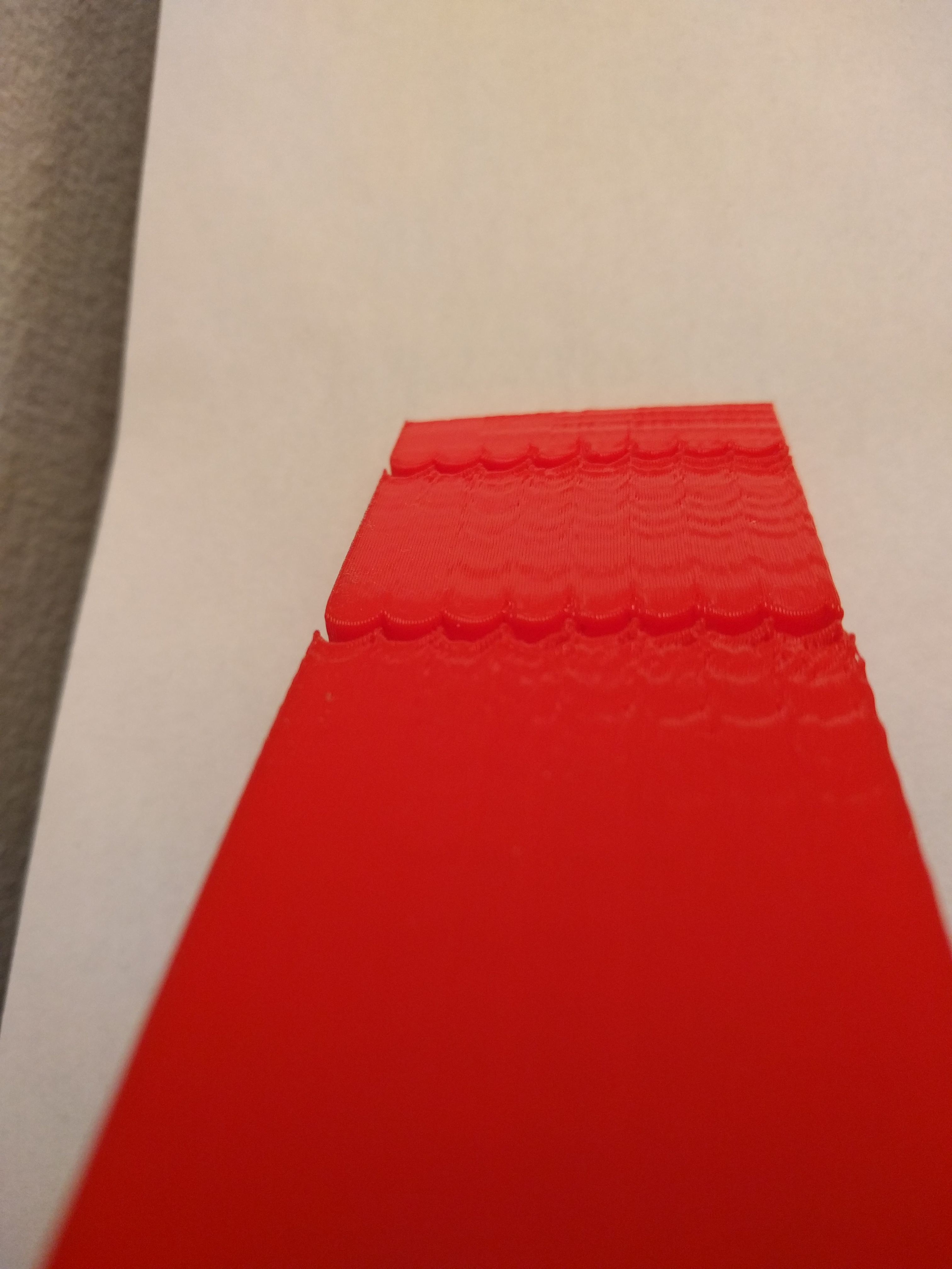
y face:
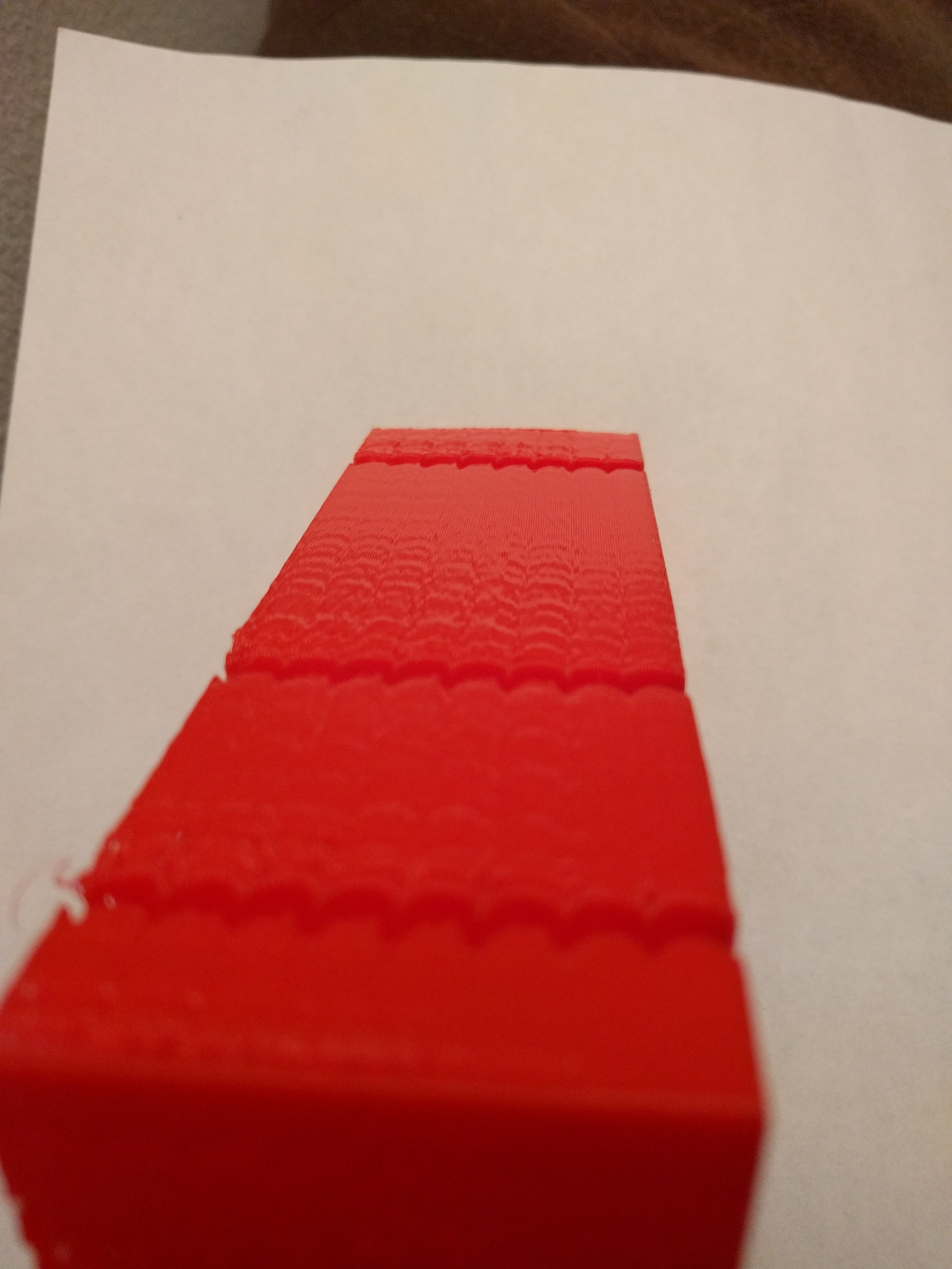
The bottom notch was at 3000mm/s^2, the next at 5000mm/s^2, then a few notches at 8000mm/s^2, then 10000mm/s^2, then I tried 10000mm/s^2 with PA disabled (but I could not observe an impact). Speed is 100mm/s, square_corner_velocity at 5.
Any thoughts?
-Kevin
KevinOConnor
on 19 Dec 2019
Hi Kevin, thanks for giving it a try! This is indeed strange, I see 2 possibilities: overlapping oscillations from the previous turns as you suggested, or oscillations of different frequencies that are excited together (e.g. if a frame and belts have different frequencies). However, on the first picture I see that the ringing at the far end corner do not appear to have such behavior (i.e have just a single frequency), so the first theory is more likely, and you could probably measure the ringing on each axis right after the first corner on that axis. Alternatively, I would just try to use 11.1-11.4 mm per 3 cycles measurement, as this appears to be the 'stabilized' mode of ringing. This maps to the frequency of approximately 26-27 Hz if I computed it correctly, and it can be used to calculate the min ringing time and max jerk parameters. Anyways, these do not have to be very precise. Acceleration tuning is more sensitive, but it's better to print a tuning test, with values spanning the frequencies of 25-35 Hz in this case (actually, it's probably better to cover at least 20-40 Hz range, i.e. 0.000016-0.00006 compensation parameter).
dmbutyugin
on 19 Dec 2019
@aschor thanks! I'll need to look more into these errors, in this case I'd say it looks more likely like some problems in switching between the printing modes (e.g. maybe some delays need to be adjusted?)
@Angelol125 limiting jerk can reduce acceleration on the short moves - so at some point you won't see a decrease in time on a small print like a test cube even if you increase max acceleration further. This is expected and, in fact, is desired behavior. So the docs do not advise to change max accel (except for measuring the ringing), and I would generally advise against using very very large values as they will not have effect. Using values of 2000-5000 is usually enough for max accel.
Re max_jerk - it should be tuned as a part of acceleration compensation tuning. The main reason to do that tuning in the first place is to attempt to increase max_jerk from it's default value (108000 in your case) to some larger value without decreasing the quality of the prints (e.g. to something like 200000-500000 hopefully).
I do not know why there could be underextrusion, maybe pa is somewhat not optimal? You said you computed the new value, how did you compute it? BTW, there's a promising update to the pa smoothing being developed and tested by Kevin - weighed positional smoothing, maybe it will improve the behavior of pressure advance around corners.
For the command to work, I think you need to compile the primer firmware part - maybe it have been cleared? But only compilation is necessary, no need to actually flash the printer.
dmbutyugin
on 19 Dec 2019
@Angelol125 limiting jerk can reduce acceleration on the short moves - so at some point you won't see a decrease in time on a small print like a test cube even if you increase max acceleration further. This is expected and, in fact, is desired behavior. So the docs do not advise to change max accel (except for measuring the ringing), and I would generally advise against using very very large values as they will not have effect. Using values of 2000-5000 is usually enough for max accel.
@dmbutyugin I see. So, in essence you recommend I lower acceleration to, say, 5000, since 7000 doesn't practically have any advantages over 5000?
Re max_jerk - it should be tuned as a part of acceleration compensation tuning. The main reason to do that tuning in the first place is to attempt to increase max_jerk from it's default value (108000 in your case) to some larger value without decreasing the quality of the prints (e.g. to something like 200000-500000 hopefully).
Ok, I will try a ringing test again to see what max_jerk the ceiling will end up being.
I do not know why there could be underextrusion, maybe pa is somewhat not optimal? You said you computed the new value, how did you compute it?
I tried to measure PA by following the Pressure Advance doc. By inspecting the outer corners of the print, I calculated PA to be at 0.144 but when inspecting the inner notches as well, PA was better at 0.0865. I don't remember where I've read it, but I remember seeing that a lower PA value is gonna be needed than the one calculated before switching to this branch, and since I went with PA=0.1 prior to switching to this branch, I settled with 0.0865, which seemed logical.
BTW, there's a promising update to the pa smoothing being developed and tested by Kevin - weighed positional smoothing, maybe it will improve the behavior of pressure advance around corners.
Yes, I've seen this weighed positional smoothing branch, and even though I find it very exciting and interesting, I haven't given it a try yet.
For the command to work, I think you need to compile the primer firmware part - maybe it have been cleared? But only compilation is necessary, no need to actually flash the printer.
I didn't understand you here, what command are you referring to, this one?
~/klippy-env/bin/python ~/klipper/klippy/klippy.py ~/printer.cfg -d ~/klipper/out/klipper.dict -i /path/to/troublesome.gcode -o /dev/null
Angelol125
on 19 Dec 2019
I recompiled the MCU firmware and flashed it, I hadn't in a while. I'll do no testings on max_jerk, and if I don't get mcu error I'll try again my previous "failing" gcodes, I'll keep you posted.
By the way, I tuned P.A. before and after accel_compensation, and there is honestly no difference on P.A. (I'm on bowden).
edit :
- accel_compensation works so well that @5000mm/s² , corner_velocity=5, P.A. activated and min_jerk set ... I get no ringing at all from max_jerk=50000 to 600000 (I did not test further)
- smooth PA with it surprised me well : before smooth PA on the previous branch, I couldn't go higher than 60000 with PA activated (but maybe higher P.A. value, depends on the filament). Now with P.A=0.73 the extruder did not die, even at 600000 jerk. (clone BMG extruder, 3:1 ratio on TMC2208 uart and spreadcycle)
TBH, I didn't hear much of a difference in the extruder speed between 300k and 600k max_jerk value. So I wonder what would be a "good" value to set , what are other's values ?
aschor
on 19 Dec 2019
@Angelol125
So, in essence you recommend I lower acceleration to, say, 5000, since 7000 doesn't practically have any advantages over 5000?
Yes, I would set the max accel at around 5000.
I didn't understand you here, what command are you referring to, this one?
~/klippy-env/bin/python ~/klipper/klippy/klippy.py ~/printer.cfg -d ~/klipper/out/klipper.dict -i /path/to/troublesome.gcode -o /dev/null
Yes, this one.
@aschor
TBH, I didn't hear much of a difference in the extruder speed between 300k and 600k max_jerk value. So I wonder what would be a "good" value to set , what are other's values ?
I would use the highest value that still has good quality and does not show signs of 'torturing' the printer. If 600K works for you - I'd use that one. I use 500K if I recall correctly. Anyway, it's great that it works well for you.
dmbutyugin
on 22 Dec 2019
@dmbutyugin Hello again. Found some time today so I compiled the firmware and run the command. This is the output I got.
I hope this helps.
Angelol125
on 23 Dec 2019
Thanks, I will try to take a look at it some time soon.
BTW, @KevinOConnor, any success using these values for ringing frequency? Any further issues?
dmbutyugin
on 24 Dec 2019
@dmbutyugin - I haven't had a chance to run further tests. I hope to do that in the next few days.
-Kevin
KevinOConnor
on 26 Dec 2019
@manoukianv could you also give Bezier scurve branch a try and post your results? It would be interesting to compare your results in this case and work-resonance-20190928 branch. You could probably even use your existing print to measure the ringing frequency(-ies), as long as you know the print speed of the external perimeter.
dmbutyugin
on 3 Jan 2020
@dmbutyugin i post the result on the other branch :/ thr comparaison beetween Bezier & resonance branch. Resonance have best results in the short tests : i just set the min_jerk param, and it don't improve result with an accel_order=2.
 manoukianv
on 4 Jan 2020
manoukianv
on 4 Jan 2020
I started playing with this on my Creative3D Elf which is a CoreXY with a wobbly frame. I had previously stiffened the X axis as it was the most wobbly and wanted to see if s-curve could help. I had great results. The cube on the left was printed at 150mm/s with PA at 0.08 and the right was 120mm/s with no PA (I was on the wrong branch of s-curve-exp)
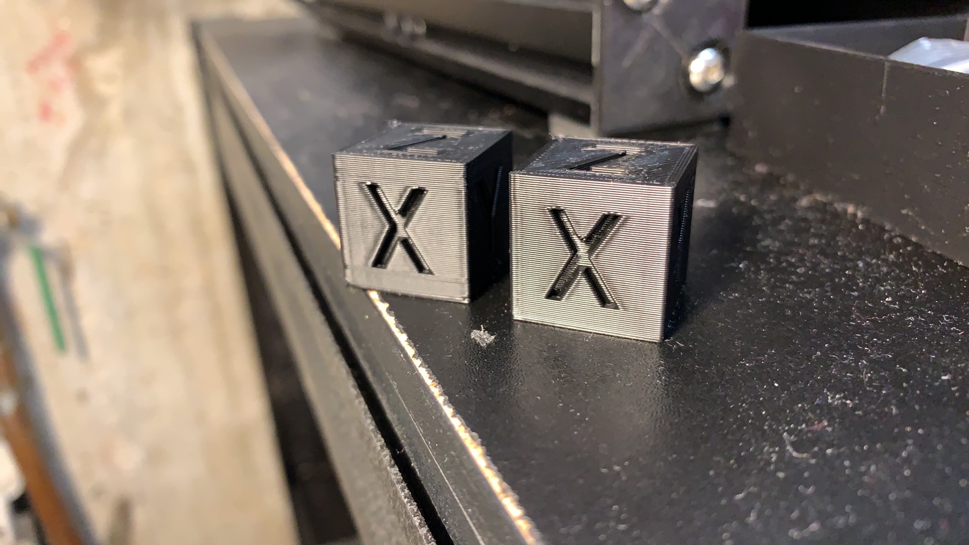
I could immediately see and hear much less wobble on my printer frame. I still think I need to stiffen the Y axis, but it is a vast improvement.
I've also printed some larger more complicated prints and had been suffering from z artifacts along the Y at certain print heights that all but disappeared here. I don't have great pictures of them right now.
I had to run at 150mm/s 8000 max accel to see artifacts in both dimensions on the test pieces. The Y axis came out pretty cleanly but the X Axis was ringing pretty bad (I'm assuming it's because the corners dip into the more wobbly Y axis and therefore ring.). I did print the piece oriented at 45 degrees and got the same results there. in my prints 3 out of 4 orientations resulted in a 75Hz frequency by my calculations. The other was slightly lower (around 70) so I just used 75Hz for my math. I think my max Jerk is done by calculation to be 225000 but I'll have to look up my Accel compensation.
If there are any specific tests you'd like me to run, I'd be happy to help. I couldn't find the specific Bezier curve branch in the github listing so I wanted to be sure I have it correct before I test it.
 slavedas
on 6 Jan 2020
slavedas
on 6 Jan 2020
@slavedas thanks, you can use scurve-c-combine-smoothpa branch. This is how to enable it, and how to tune it.
Sorry, but at this point I did not fully get which branch you have tested so far, and what your results refer to. But I guess your calculations of the ringing frequency and max jerk value is already a start of the tuning and you can use them for the correct branch.
dmbutyugin
on 7 Jan 2020
@dmbutyugin thanks. I did figure out to use scurve-c-combine-smoothpa and I tuned it.
Interesting note, the 45 degree print was nearly identical to the default print. I expected a difference. My X Axis has much fainter ringing than my Y, but when I turn the model 45 degrees, the same side of the model has the fainter ringing even though it should now be sharing any structural issues. Best I can tell this is about the steppers themselves.
I added stiffening to my frame last night and my ringing frequency went down. Does that make sense? I'm now seeing a pretty standard 51Hz/35Hz split.
The branch I was referring to was the Bezier Spline branch you referenced above. I wasn't sure which one that was.
slavedas
on 7 Jan 2020
Hi all,
Recently I was working on an issue that could manifest itself as 'timer too close' or 'no next steps' errors when the print was sliced with very high precision (more details and the explanation for the effect can be found in this comment). This should be fixed now, thanks @BlackStump for reporting. However, since this was a non-trivial amount of work, there is a small chance that some other bugs were introduced on the way, even though I have tested it pretty extensively. Please let me know if you run into any issues with the update (and please attach klippy.log together with the problematic GCode file).
Separately, you don't really have to wait a few hours into the print only to see that there is some bug. You can run Klipper in dry-run mode, which will run all of the GCode analysis and move planning without actually printing anything. You can simply upload your GCode to Raspery PI, then (assuming you use OctoPrint) ssh to it and run:
~/klippy-env/bin/python ~/klipper/klippy/klippy.py ~/printer.cfg -i ~/.octoprint/uploads/your_model.gcode -o /dev/null -v -d ~/klipper/out/klipper.dict > /tmp/klippy-test.log 2>&1 && tail /tmp/klippy-test.log
Be patient, depending on the size of the GCode, dry run can easily take several minutes on a file of 2-3 MB. If you see some segmentation fault or other error report - that's a bad sign :) If you see something like
DEBUG:root:; Max time of 12345.6789
it means that dry-run succeeded. If you see that klipper.dict was not found - it means that you need to recompile the firmware
cd ~/klipper/
make
because you apparently cleaned it after flashing, or maybe reinstalled Klipper without re-flashing.
dmbutyugin
on 20 Feb 2020
With the latest improvements, the printer has become jerky, lines are printed with jerks That you overreached in these fixes
moveq: force partial queue flushes when it grows too large
and
moveq: more aggressive flushing on junction points with zero velocity
and
moveq: more latency metrics to track and report.
ShohninDmitriy
on 21 Feb 2020
2 my printers began to twitch after the update will have to roll back to 6447d59f9b3eed9f0b2dc1d496003722323cf86c
ShohninDmitriy
on 21 Feb 2020
Thanks, I hope it should be fixed now (as of a223a203dcad66040860dbee2783f62b20e413d8)
dmbutyugin
on 22 Feb 2020
@dmbutyugin Thank you, everything was fine
ShohninDmitriy
on 22 Feb 2020
BTW, I've created an updated test model, which was inspired by BlackStump's model. The new model has some changes - e.g. it has notches of different depth and cuts at different angles. Also I suggest a slightly different and more streamlined process for measuring ringing frequencies.
Your feedback on the model and the measuring process is welcome.
dmbutyugin
on 23 Feb 2020
When I loaded the test model in Simplify3d, the wall with a recessed "X" runs in the Y axis direction (and vice versa). Is this the proper orientation, or should I rotate it so that the wall with a recessed "X" runs in the X axis direction?
w1ebr
on 23 Feb 2020
@w1ebr Yes, that's intentional. Ringing of X axis shows _along_ Y axis and vice versa. So you don't need to rotate anything - just print the model in the default orientation.
dmbutyugin
on 23 Feb 2020
@dmbutyugin - FYI, I printed your new test model described at https://github.com/KevinOConnor/klipper/issues/57#issuecomment-590115120 on my Makergear m2 printer.
I used 100mm/s perimeters, spiral mode, 0.28mm layer height, pa disabled, max_accel=7500, default accel_to_decel, square_corner_velocity=5, Klipper master (16e59511), TUNING_TOWER command as documented.
Some feedback:
- The model shows significant ringing on the printer.
- Unfortunately, the notches don't show a particularly clear result. Different notches are showing slightly different ringing periods and the higher accel bands seem to excite additional (higher) frequencies. My guess is that the carriage is still ringing when going into the next notch and that's causing other frequencies to be excited.
- Interestingly, the X and Y lettering on the inside walls show a very clear and unambiguous resonance.
- I'm curious why BAND was chosen for the tuning tower. I'd have thought the test would work just as well (or better) with continually changing accelerations.
Separately, it occurred to me that using rounded corners might be a useful approach to measuring resonance. When using a "hard corner", the X, Y, and E all end up making changes at the same time. That complicates analysis of the results. I wonder if a test could be made with a rounded corner such that Y rapidly went to zero velocity while E stayed the same and X had mild acceleration. That might make it easier to isolate the impact of the dramatic Y velocity change.
-Kevin
KevinOConnor
on 27 Feb 2020
@KevinOConnor @dmbutyugin
is this something like the model you had in mind? (ok version 2 )
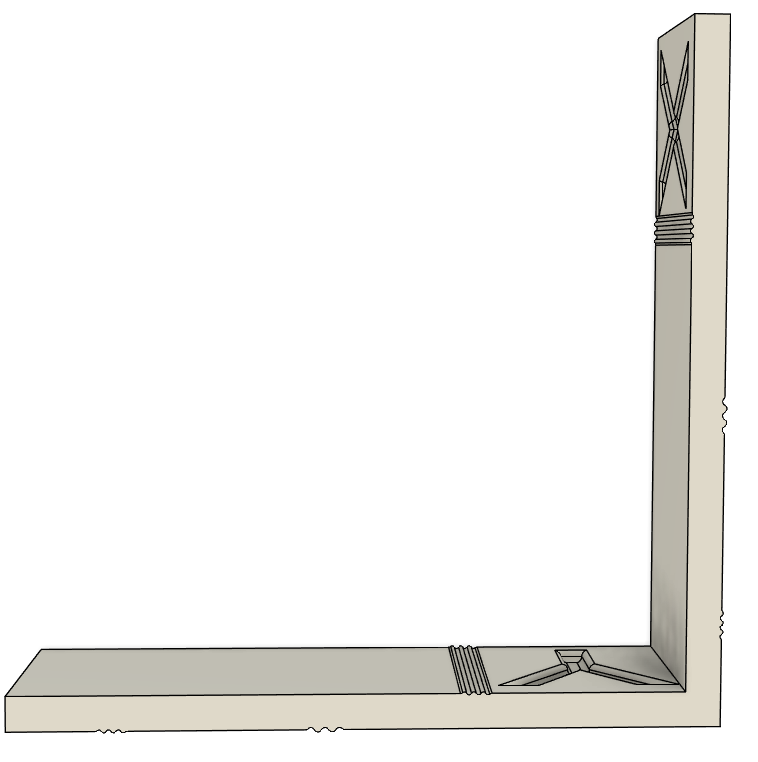
if so here it is v2
BlackStump
on 27 Feb 2020
Thank you for the feedback, Kevin!
1. The model shows significant ringing on the printer.
I take this part is good?
2. Unfortunately, the notches don't show a particularly clear result. Different notches are showing slightly different ringing periods and the higher accel bands seem to excite additional (higher) frequencies. My guess is that the carriage is still ringing when going into the next notch and that's causing other frequencies to be excited.
I suppose slightly different ringing periods are possible? E.g. because of different carriage/bed positions, so the frame or belts stiffness may vary a bit. I have seen this effect on my delta printer too, the variance was within a few Hz (like, 46-48 Hz). In principle, this is good that we can see different ringing periods across the bed (if that effect is real). BTW, would it help in your case if the distances between notches were larger, what do you think? I feel like right now the notches are a bit cramped.
I suppose at high accelerations the carriage may still be resonating from previous turns. Then if you add two cosines (or sines) with different phase offsets, you can get oscillations of 2x frequency. Maybe that's what you see. Maybe if resonances are visible before then, there is no need to look at high accel bands?
3. Interestingly, the X and Y lettering on the inside walls show a very clear and unambiguous resonance.
Yes, it seems they behave like other notches. Oh, do you mean they show more clear ringing than the notches themselves?
4. I'm curious why BAND was chosen for the tuning tower. I'd have thought the test would work just as well (or better) with continually changing accelerations.
First, the model has natural bands from the geometry (to make it easier to separate ringing from other printing defects). More importantly, in my opinion it is easier to mark waves on the test model and then measure the distances between marks when they ringing is constant within some reasonably wide band.
Separately, but less importantly, the test model is best printed in smooth spiral vase mode. But then all moves have different Z heights. So all moves will have changes of the test parameter. And then changing some parameters (e.g. smooth time) requires flushing stepper queues, which usually makes toolhead to stop; if this happens for every move it is not acceptable. OK, tuning tower for accel will not have this problem, but then having some tests with bands and some without may be confusing.
Separately, it occurred to me that using rounded corners might be a useful approach to measuring resonance. When using a "hard corner", the X, Y, and E all end up making changes at the same time. That complicates analysis of the results. I wonder if a test could be made with a rounded corner such that Y rapidly went to zero velocity while E stayed the same and X had mild acceleration. That might make it easier to isolate the impact of the dramatic Y velocity change.
I wonder? I will try to think about it, but my worry is that arcs would act symmetrically for X and Y axes (i.e. if one axis decelerates, the other one will have to accelerate over similar, e.g. mirrored profile). BTW, I saw some ringing at very high accels in Spline Hell test @BlackStump posted a while back on this thread. However that ringing wasn't very pronounced and easy to make out.
dmbutyugin
on 27 Feb 2020
@BlackStump I wonder what kind of resonances would that model with smooth notches excite.
dmbutyugin
on 27 Feb 2020
yeah not sure, have not tested it.
BlackStump
on 27 Feb 2020
@BlackStump
is this something like the model you had in mind?
FWIW, in that model, both the X carriage and Y carriage will reverse directions during the notch. The turns are also large enough to cause the E to slow down. I was more thinking of a test that would make significant Y changes without stopping/reversing the X nor E.
Also, separately, multiple notches on a side seems to complicate the results for me. Are they needed?
@dmbutyugin
I take this part is good?
Yes.
BTW, would it help in your case if the distances between notches were larger, what do you think?
I agree - or just have one notch (or perhaps just one elaborate corner instead).
you can get oscillations of 2x frequency. Maybe if resonances are visible before then, there is no need to look at high accel bands?
It did look like I started getting 2x frequency. I agree about finding the frequency - just wanted to provide my feedback on the test.
Oh, do you mean they show more clear ringing than the notches themselves?
Yes - it seems easier to measure the frequency from the letters than from the notches.
Thanks!
-Kevin
KevinOConnor
on 28 Feb 2020
Hi all, today I pushed some changes to the S-Curve branch. They contain some optimizations of the move planner code and the new implementation of the algorithm to find suitable flush points. The new algorithm resolves some quirks of the old one which did not accept certain points, thus potentially requiring to queue many more moves than was really necessary. The new algo, together with other optimizations, should eliminate the need for the forced partial queue flushes. But functionally it should produce the same plans as before - the same accelerations, max velocities, etc. So, let me know if something got broken by accident.
dmbutyugin
on 11 Mar 2020
@dmbutyugin, is that scurve-c-combine-smoothpa branch?
Do I need to set any params/values to enable it to work? I believe there is no documentation yet for this thus my question. Thanks
 Nandox7
on 11 Mar 2020
Nandox7
on 11 Mar 2020
@Nandox7 yes, it is that branch. There are actually some docs available here
dmbutyugin
on 11 Mar 2020
Hi @dmbutyugin , I've updated to the last commit of the branch (it was quite difficult, because git told me of some branch divergence between my previous update and today).
So I'm running through calibration steps again. I have a few remarks already :
1) ringing-frequency - step 11 (restore max accel) => nowhere is it specified WHEN we can restore accel_order 6. However, further in the docs (after setting min_jerk), we are suggested to print the model again and see if it has improved => I suppose that printing the model again (with tuning tower) requires to NOT restore max_accel in the config file, nor accel_order ... ? or does it ?
2) for some reason, I get layer shift that I didn't have before. on every test print. Maybe is it because of accel_order2, maybe is it because I updated to latest commit ? Or maybe because I get oozing quite high in the model (at 6500 accel), I'll do more tests about that
aschor
on 14 Mar 2020
@aschor thanks for the feedback! I will try to incorporate that feedback into the docs. To answer your questions:
If you have switched to the S-Curve branch already (and have
acceleration_orderin your config), you only need to changemax_accelvalue in the config, you can switch to ao=2 usingSET_VELOCITY_LIMIT ACCEL_ORDER=2command as stated in the docs. After you runRESTARTcommand the effect of that command is reverted.I only pulled some recent changes from the master branch with the last commit. There were other commits from me a few days ago, but I trust they also could not have caused layer shifts alone. Layer shifts could happen at very high accel (with AO=2 or higher), but the TUNING_TOWER command from the tuning process should make sure that you get reasonably low acceleration values in the beginning of you test print. Does it not happen? When do you get layer shifts exactly? Do you get layer shifts also when you restore a reasonable
max_accelvalue?
dmbutyugin
on 14 Mar 2020
HI, to be honnest, my last update was back late 2019 I think ("don't touch if it works ...") :
pi@octopiklipper:~/klipper $ git status
On branch scurve-c-combine-smoothpa
Your branch and 'dmbutyugin/scurve-c-combine-smoothpa' have diverged,
and have 5 and 277 different commits each, respectively.
  (use "git pull" to merge the remote branch into yours)
nothing to commit, working tree clean
for 1) => it's not clear to me If I should print the test model with AO=2 and max_accel=7000, after setting min_jerk_limit_time (end of https://github.com/dmbutyugin/klipper/blob/scurve-c-combine-smoothpa/docs/S-Curve.md#ringing-frequency ). or AO=2 and max_accel="nominal". or AO=6 and max_accel="nominal" .
for 2) I've used exactly the command in the docs (starting at 1250, then it jumps to 2000 because of the weirdness of tuning tower, then +500 up to 7000).
first test print : I get layer shift at 2000 mm/s/s, at height 9.9mm, then at 30.8mm (and 4500mm/s/s)
second test print : I lowered tmc run current on X and Y to 0.7 Amp (from 0.9) (spreadcycle) => layer shift at 52.11mm (6500 mm/s/s).
I'm on a coreXY.
running a third test print with min_jerk_limit_time and max_jerk set in config (@AO=2), and tuning tower engaged. I'll see what happens :)
edit : 3d test, no layer shift. but no improvement for ringing with only jerk settings added, maybe it should have been done with AO=6.
3) (new) It seems that ideal acceleration-compensation (in theory) does not rely on acceleration. So for tuning it, shouldn't we set a "desired acceleration" where ringing is actually visible ? When I read the tuning process, I'm enclined to set the "desired acceleration" to a value where I see no ringing ... but then what would I tune ? the "absence" of ringing that was already there ? Or maybe it's max_jerk high value that will make ringing appear ?
interestingly, I've got ringing @100mm/s print speed from 1250 to 3000, then no ringing from 3500 to 4000, then again ringing above that. maybe that is dependent from print speed (?)
aschor
on 14 Mar 2020
@aschor In my opinion it is better to update more frequently to avoid these painful updates when too many things change at once. On the other hand, you may see the tradeoffs differently.
More generally, if you experience problems with update, I would suggest you to run the first part (where you measure the ringing frequency) using the mainline Klipper branch. Then you can isolate the changes happened in the mainline Klipper from the changes in S-Curve branch. And see if you get layer shifts during the tuning or not.
After you finish with that, you can switch to S-Curve (scurve-c-combine-smoothpa) branch, add calculated min_jerk_limit_time, max_jerk, and acceleration_order = 6 to your printer.cfg and continue with tuning.
edit : 3d test, no layer shift. but no improvement for ringing with only jerk settings added, maybe it should have been done with AO=6.
If you are talking about the test print to check if the ringing has improved, then yes, you should do that with AO=6 if you want to see the improvements for ringing. So, for (1): after setting min_jerk_limit_time you should print the test model with AO=6 (or 4) and normal max_accel. However, this part about printing the model the second time is optional and the instructions may be confusing, I plan to update them. Maybe it would be best to run this test with max_accel=7000 and use the same TUNING_TOWER command as before. Now that I think about it, it should also help you choose the right acceleration value for acceleration compensation tuning.
It seems that ideal acceleration-compensation (in theory) does not rely on acceleration. So for tuning it, shouldn't we set a "desired acceleration" where ringing is actually visible ? When I read the tuning process, I'm enclined to set the "desired acceleration" to a value where I see no ringing ...
Yes, acceleration compensation should not depend on acceleration value. And generally you are right that you should better print it with the acceleration that makes the ringing most visible.
interestingly, I've got ringing @100mm/s print speed from 1250 to 3000, then no ringing from 3500 to 4000, then again ringing above that. maybe that is dependent from print speed (?)
Ringing depends on acceleration time. And that one depends on the distance, initial velocity and acceleration value. Now distances stay the same in the test model as Z increases, and initial velocities depend on square_corner_velocity and should also be constant. So when TUNING_TOWER changes acceleration, this changes acceleration times, and with some values you get larger ringing than with others. The idea behind TUNING_TOWER is exactly that - we cannot predict in advance which acceleration will induce ringing the most, so we try different values.
dmbutyugin
on 14 Mar 2020
Hi, @dmbutyugin
just got an mcu shutdown while testing accel_comp. Model was sliced in vase mode, accel was set @7000mm/s² and max_jerk @1000000 as specified. It happened on the first layer.
it's the first time in a while that I tried vase mode, my last attempt being a big failure on a test cube ... is it related to vase mode ?
dryrunning the file did not throw any error (~/klippy-env/bin/python ~/klipper/klippy/klippy.py ~/printer.cfg -i ~/.octoprint/uploads/ringing_tower_accel_comp_vase.gcode -o /dev/null -v -d ~/klipper/out/klipper.dict > /tmp/klippy-test.log 2>
&1 && tail /tmp/klippy-test.log)
(tuning tower command :
TUNING_TOWER COMMAND=SET_VELOCITY_LIMIT PARAMETER=ACCEL_COMPENSATION START=0.000006 FACTOR=0.0000004 BAND=5
)
klippy.log
klippy-test.log
ringing_tower_accel_comp_vase.gcode.txt
aschor
on 15 Mar 2020
Ok, I tried a 2nd time to print the file ==> mcu_shutdown at the exact same position (on the first layer).
I re-sliced the test model without vase mode => mcu_shutdown.
I don't know what happens here, but that's very unfortunate !
my next try : to NOT use tuning tower for accel_comp parameter...
aschor
on 15 Mar 2020
ok, @dmbutyugin , I rolled back to commit 986e9c884a28a6e67aa03ae168e199eec1e027c8 (before the update of March 11) and the file that was previously failing is not failing.
however, when firing "set_velocity_limit" command, I'm not getting data about accel_order, nor jerk, nor accel_comp, they are not there. What am I missing I don't know oO
edit : it's very unclear to me how to revert to a previous state of the branch, in fact. so for now this is what I have just done : git reset --hard 7f812ea642c22cf510e5c498d9ed2f4470518d91 (so now, I'm in a state of "march 5, 27 commits behind". because my previous checkout had made me leave smoothpa branch it seems. Back to test prints I suppose ... (but definitely, the print did not crash on kevin's master so there is a kwirk with smoothpa branch related to acceleration_compensation)
aschor
on 15 Mar 2020
@aschor Yes indeed, when you checkout 986e9c884a28a6e67aa03ae168e199eec1e027c8 commit, you switch back to the master branch. Commit 7f812ea642c22cf510e5c498d9ed2f4470518d91 should be good. I will also take a look at the logs you've posted, gcode, and see if I can find a problem. So, just to be clear: when you ran the TUNING_TOWER for ACCEL parameter, you did not have this issue, right? Only now that you are trying to tune acceleration compensation?
dmbutyugin
on 15 Mar 2020
@dmbutyugin exactly, I did not encounter this with tuning_tower for accel parameter
but NO, I already tried to print with 7f812ea642c22cf510e5c498d9ed2f4470518d91 (just now in fact) and I still get the mcu_shutdown, at the exact same place. without tuning tower (with manual set_velocity_limit ACCEL_COMPENSATION command).
I'm trying now with fb17a978a23ae8a7fe4a72ff8371dcb4af97eed2 .... (and I will double check that with tuning_tower accel parameter I get no issue)
edit : no way, fb17a978a23ae8a7fe4a72ff8371dcb4af97eed2 still crashes at the exact same place in the print. next step : exact same gcode without acceleration_compensation commands, and with manual conf of it at 0
edit again : with jerk=1000000 and changing in the gcode tuning tower line to "accel" parameter, the same gcode DOES NOT crash. so yes, this is double checked that the issue is in acceleration_compensation. But it does not appear in the dryrun, and that is strange.
aschor
on 15 Mar 2020
@aschor thanks for double-checking a few other commits! If it is not too much bother for you, could you also check c27fc02272b9a2f32f3ce908c70c968d833c0a3d commit with accel_compensation tuning tower? This commit is before any recent changes to the code of the S-Curves.
Separately, the reason why this issue does not appear in the dry-run is because the error is triggered by the part that run on the printer controller (MCU), and that one, unfortunately, is not executed as a part of dry-run simulation.
dmbutyugin
on 15 Mar 2020
@dmbutyugin tried just now : does not work either. I've modified my gcode and removed temperature requirements, removed the filament, so that I can test faster ... is there anything more I could do to provide more info ?
I'll try going back in time and see if any commit works (?).
edit : doesn't work either on the previous commit I was on before upgrading :
commit 912b3708e87c422e50088448fd14350573f90caf
Merge: fe1b57ed 72161d04
Author: NeT net@a.com
Date: Thu Dec 5 02:29:07 2019 +0100
I'll try with settings I had before re-tuning ringing, with lower max acceleration, and see what happens. because before re-tuning, that "no next step" did not happen (with this config :
min_jerk_limit_time: 0.027725966 + accel_compensation: 0.0000181 so accel_compensation was turned on)
fyi my mcu is an skr 1.3
aschor
on 15 Mar 2020
OK, I hope I have enough info to try to reproduce, however I do have a different MCU. I will ask more questions if needed, thanks! We should be able to find the root cause and fix it one way or another.
dmbutyugin
on 15 Mar 2020
Hi @dmbutyugin , I don't know if that will be of any help, and after that I'll wait for your specific tests requests. But here is what I tried :
with the following file (⚠️ do not print with filament in extruder, or edit it to add temperature gcode) :
ringing_NOTEMPERATURE_debug.gcode.txt
(tuning tower command for acceleration_compensation included in the gcode)
on a fresh klipper repo, up to date, no tuning on the printer after boot : prints just fine (at least the first few layers, I did cancel then because I was printing with no filament loaded)
change line 46 from set_velocity_limit jerk=500000 to set_velocity_limit jerk=1000000 and I get a crash on the first layer, repeatable, every time, at the same place => interaction between jerk and acceleration compensation ? or board (mcu) specific bug maybe ? I'll let you do your magic :)
relevant (?) config settings :
- acceleration_order: 6
- max_accel: 7000
- min_jerk_limit_time: 0.025641026
- from virtual sd
- bed mesh levelling activated
- lpc1768 board (skr 1.3)
aschor
on 16 Mar 2020
@aschor OK, it took me considerable amount of time to find the root cause, but it should be fixed now. The problem was related to the safety checks for the stepper motors, which I did not update at first to account for the fact that maximum _stepper_ acceleration can significantly exceed the configured max_accel value - and so they falsely triggered and halted the printer. This problem was more prominent during the tuning process, when aggressive max_accel and max_jerk values are used, and could manifest less (if at all) during the 'normal' prints. This should be fixed in 5dd643796f71a707dc1e816d7055767d844a5aef commit.
dmbutyugin
on 19 Mar 2020
@BlackStump Sorry, I actually did not notice that you've published a different model. Have you tried to print it? Does it show ringing? Separately, I had a couple of comments:
- The model design seems to assume that it will be printed in the counter-clockwise direction. This is my experience with Cura, that it seems to (usually?) slice the model in spiral vase mode that way. But it is probably not guaranteed, and can work differently in other slicers, can it not? I'm also not sure if there is a way to 'force' any given printing direction.
- The model has groups of several smooth notches following each other. While I did not print the model, I suspect that multiple consecutive notches can cause oscillations from previous notches to 'carry over' to the next ones, thus creating an interference picture of sorts, making measurements more difficult. I wonder if a single notch per group is sufficient.
dmbutyugin
on 19 Mar 2020
@dmbutyugin I did come to same conclusion that multiple smooth notches is not ideal, I did revise the model but have not tested it as one printer stepper driver failed and the other is waiting on the slow boat for a upgrade part. At the moment I think your model shows the ringing best.
BlackStump
on 19 Mar 2020
@dmbutyugin if you would like to test the model.
Accel_Test_V4.zip
I used S3D and it also prints counter-clockwise it that consistent across slicers, I do not know.
BlackStump
on 20 Mar 2020
Hi folks,
Recently I've been working on re-implementing acceleration compensation and integrating the smoothing from #2030 into S-Curve branch. This work is done now. The new acceleration compensation method supports different resonance frequencies for different axes now. It should also improve handling of centripetal acceleration. This also allowed to rework and, hopefully, streamline the tuning process. Now as the very minimum it is only necessary to measure the ringing frequencies for X and Y axes, put some values into the config - and that's it. You can always run fine-tuning later if you prefer. I encourage to give it a try and share your feedback. The branch is scurve-smoothing, the updated documentation is available here. However, note that it is a bit more computationally demanding than the previous branch. Raspberry Pi 3 should have no issues, and even a device up to ~10x slower should be fine, in principle.
If you have been using scurve-c-combine-smoothpa branch, you can give new branch a try without doing any extra tuning, but do note that you will need to update printer.cfg. To check a new branch in the existing installation, run on the Raspberry Pi
$ sudo service klipper stop
$ cd klipper
$ git fetch s-curve-exp
$ git checkout s-curve-exp/scurve-smoothing
$ sudo service klipper start
Then assuming you had the following values in your printer.cfg:
[printer]
acceleration_order: n
min_jerk_limit_time: a
max_jerk: b
accel_compensation: c
you will need to add the following two new sections with the values:
[smooth_axis]
smooth_x: a * 2 / 3
smooth_y: a * 2 / 3
accel_comp_x: c
accel_comp_y: c

[scurve]
acceleration_order: n
min_jerk_limit_time: a
max_jerk: b
So, essentially a new section [smooth_axis] is needed, and acceleration compensation parameter goes there (separately for X and Y axes), and acceleration_order, min_jerk_limit_time and max_jerk values were moved into a new [scurve] section. If you did not use any of the parameters above, you can simply not include them into the updated configuration. Also, if you have been using AO=6 before, please give AO=4 a try. Unlike the previous acceleration compensation implementation, the new one does not require AO=6 at all (AO=4 is enough) and if AO=4 works well, it might be possible to optimize the codepath for AO=4 case and reduce the 'calculation footprint'.
Also, if you have the results of the previous ringing frequency measurements at hand, you can fill the sections with the following suggested values (also see here):
[smooth_axis]
smooth_x: ... # 2 / (3 * f_X)
smooth_y: ... # 2 / (3 * f_Y)
accel_comp_x: ... # 1 / (2 * π * f_X)^2
accel_comp_y: ... # 1 / (2 * π * f_Y)^2

[scurve]
acceleration_order: 4
min_jerk_limit_time: ...  # 1.0 / max(f_X, f_Y)
where f_X and f_Y is the ringing frequency of X and Y axis respectively. But please take a special care to not mix X and Y frequency (X shows ringing _along_ Y axis and vice versa). If anything, re-printing a test model may be easier.
dmbutyugin
on 22 Mar 2020
Separately, note that improving quality does not always mean printing slower. Of course, YMMV, but I thought about sharing an example of 3D benchy printed on master Klipper branch and using this S-Curve branch. The model sliced at 100 mm/sec speed (50 mm/sec for external perimeters), 0.2 mm layer. I printed it on master Klipper branch with max_accel = 3000, and then exactly the same GCode on scurve-smoothing branch with parameters tuned for my printer, and specifically max_jerk = 775000 and max_accel = 7000 (essentially no limit). The print on scurve-smoothing branch finished a few seconds faster than on the master branch. The results are the following:
| master | scurve-smoothig |
|----------|------------------------|
|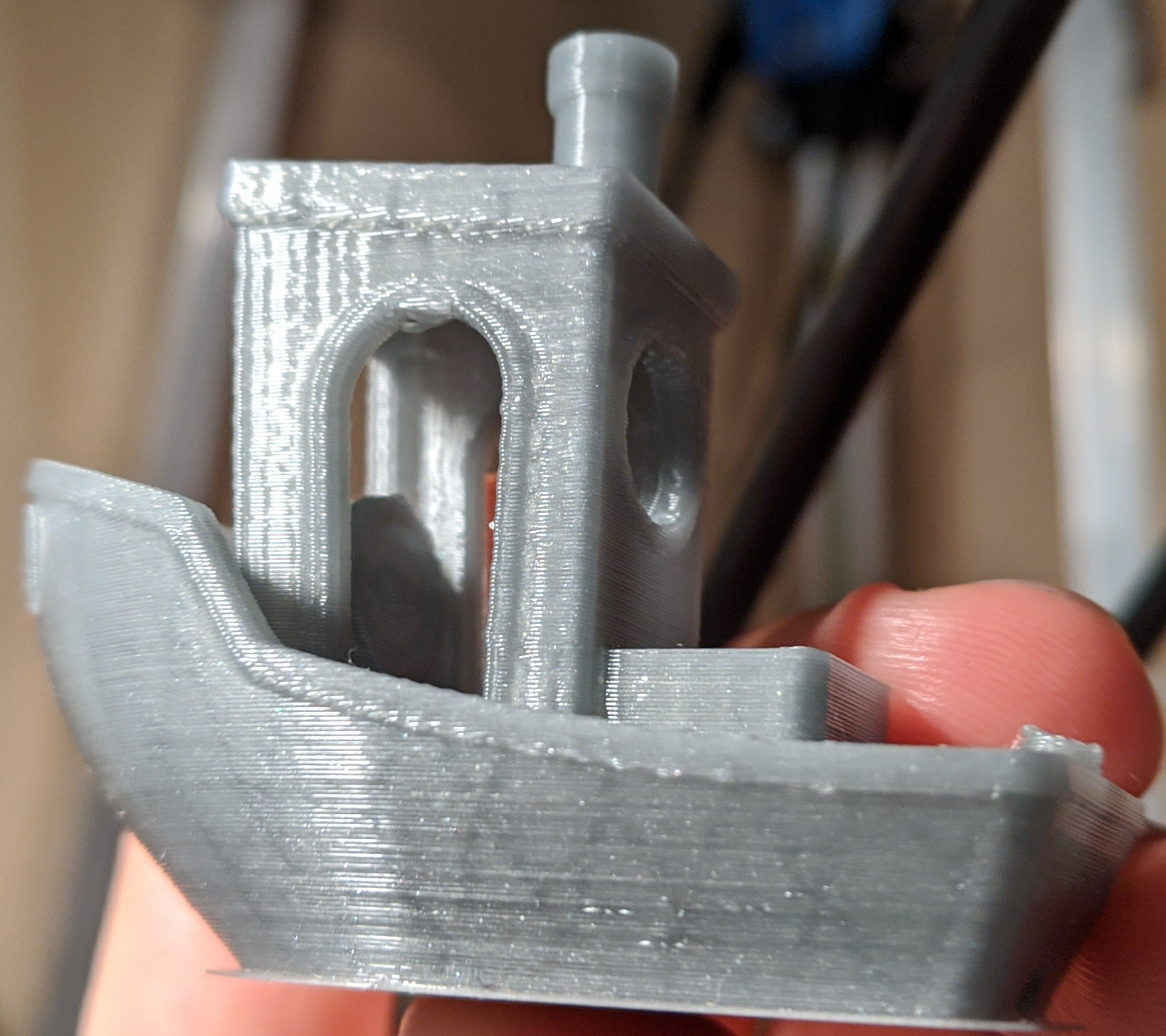 |
|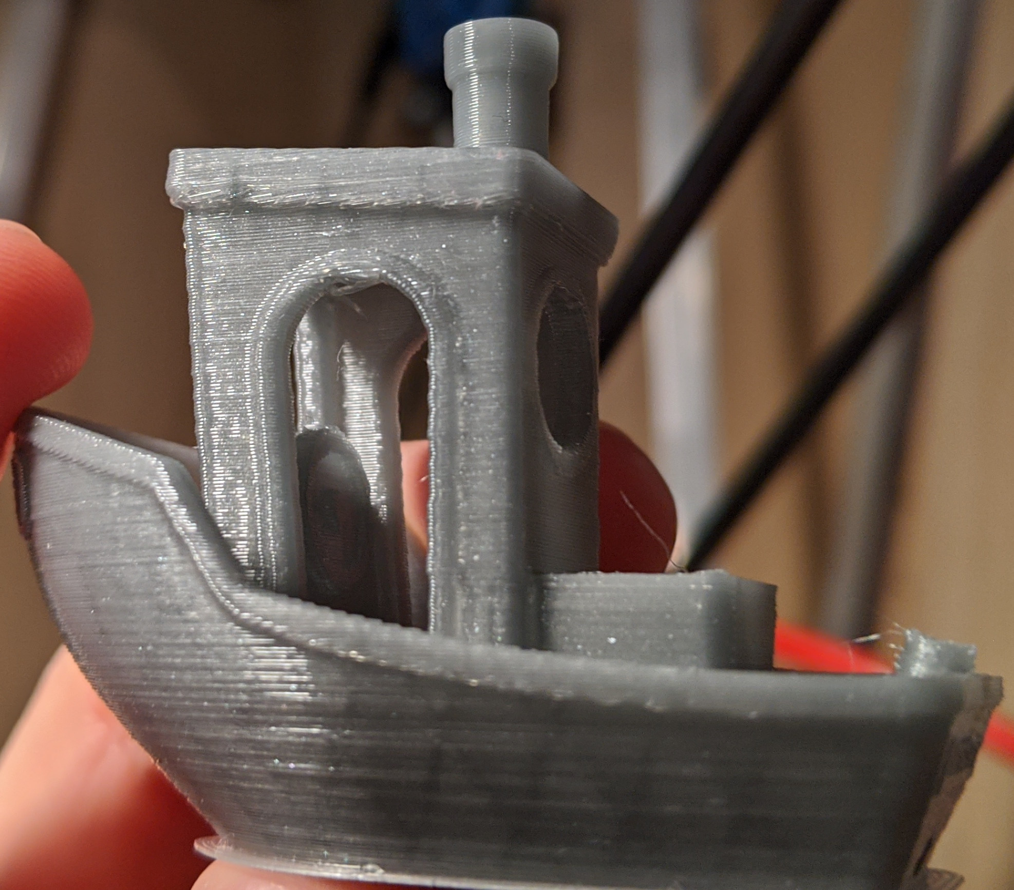 |
|
|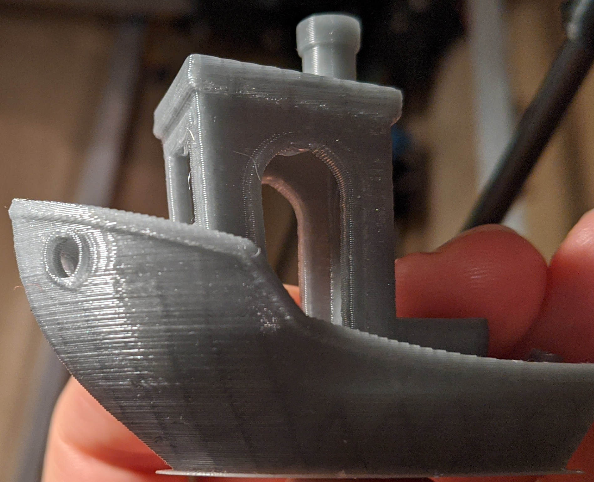 |
|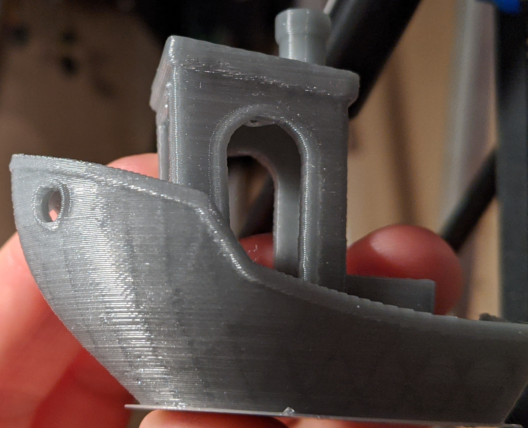 |
|
The quality on master branch is not bad at all. But one can clearly see some ringing around 90 degrees corners, e.g. on a cabin and the hole for the anchor chain. Scurve-smoothing branch print does not show ringing, and it printed the same amount of time (even a few seconds faster). Again, this does not mean that one can always achieve such results, but just to show that tuning the parameters can reduce the time penalty in general.
dmbutyugin
on 22 Mar 2020
hi @dmbutyugin
awesome work !
reading the docs,
Basic configuration -> You can print the ringing test model now following the steps (1)-(6) from above
does that mean that smooth_x/y and accel_comp_x/y DO work with acceleration order 2 ?
Fine Tuning -> Best tuning conditions
at what acceleration order should the test be performed ? I suppose "2" to see the ringing better ? same question for jerk tuning ?
(because the previous steps stipulate to add scurve section in printer.cfg with a.o=4, and then it is not changed for tests)
edit : 3d question) does this mean that branch "scurve-c-combine-smoothpa" is going to be replaced by "scurve-smoothing", or will both evolve in parallel ?
aschor
on 23 Mar 2020
Hi @aschor!
Basic configuration -> You can print the ringing test model now following the steps (1)-(6) from above
does that mean that smooth_x/y and accel_comp_x/y DO work with acceleration order 2 ?
Yes, it is possible to enable [smooth_axis] module without even enabling [scurve] module, and it will work. It will provide pretty much the same effect as the code from #2030 pull request by Kevin.
Fine Tuning -> Best tuning conditions
at what acceleration order should the test be performed ? I suppose "2" to see the ringing better ? same question for jerk tuning ?
(because the previous steps stipulate to add scurve section in printer.cfg with a.o=4, and then it is not changed for tests)
It is better to tune at the current config in printer.cfg (i.e. with ao=4). In order to increase the ringing JERK setting is increased as a part of testing process. However, it is possible to fine-tune acceleration compensation and PA with [scurve] disabled. But if you plan to use that module, I would suggest to keep it for tuning as well, and use ao=4.
edit : 3d question) does this mean that branch "scurve-c-combine-smoothpa" is going to be replaced by "scurve-smoothing", or will both evolve in parallel ?
I hope that if "scurve-smoothing" shows at least not worse results than the other branch and is well-received, we can continue with it, and the development of "scurve-c-combine-smoothpa" will cease. I think that acceleration compensation approach in "scurve-smoothing" is more robust and allows further experimentation. Also the new code in this branch is better isolated from the main Klipper code, which means that commenting out [scurve] and [smooth_axis] gives users _almost_ the same mainline Klipper branch with minimal exposure to modifications. I would need Kevin's opinion on this, but I have some hope that this will help to progress with integrating this code into the mainline Klipper codebase.
dmbutyugin
on 23 Mar 2020
Awesome,, !!! thx you and Kevin ... Nice work!
 CroveR99
on 24 Mar 2020
CroveR99
on 24 Mar 2020
Wow - just wow!!!
I just modified my printer to Core-XY and gave these instructions a try:
https://github.com/dmbutyugin/klipper/blob/scurve-smoothing/docs/S-Curve.md#switch-to-s-curve-acceleration-branch
The results were absolutely astounding, and even printing at 100mm/s with
7000 acceleration (while testing) - the ringing went down to near zero. I'm
going to keep this branch and report back if I see any issues.
Thanks a lot.
Dushyant Ahuja
On Tue, 24 Mar 2020 at 15:49, CroveR99 notifications@github.com wrote:
Awesome,, !!! thx you and Kevin ... Nice work!
—
You are receiving this because you were mentioned.
Reply to this email directly, view it on GitHub
https://github.com/KevinOConnor/klipper/issues/57#issuecomment-603321064,
or unsubscribe
https://github.com/notifications/unsubscribe-auth/ABQ6SCPXECWPQRJBQ64CVG3RJDJA5ANCNFSM4EIJ4S3Q
.
dushyantahuja
on 25 Mar 2020
@dmbutyugin
I get a menu error in your branch that I don't get in the master branch:
"Choice 'deck' for option 'type' in section 'menu __screen2004_static' is not a valid choice" I don't see anything wrong with the file, which works fine with the master branch.
Have you seen this before?
menu.cfg.txt
w1ebr
on 26 Mar 2020
@w1ebr you are probably at the old master branch. 'deck' support was removed recently from the master branch as well, see d39c4fe62853536b3cafd4129ef470b682194474 commit.
dmbutyugin
on 26 Mar 2020
Thank you!
w1ebr
on 27 Mar 2020
@dmbutyugin
I am getting a G28 internal error. I have attached the klippy.log file. It does not happen with Kevin's master.
G28error.klippy.log
I am looking forward to trying this!
w1ebr
on 30 Mar 2020
@w1ebr unfortunately, this is because you have dual_carriage enabled. I was under the impression that work-resonance-20190928 already supports dual carriages (smooth_axis in scurve-smoothing is branched from that one), but it seems that it only supports them on Z axis, but not on X and Y axes. I will take a look if it is an easy fix or not - otherwise I would have to ask if Kevin can add the support to that branch.
dmbutyugin
on 31 Mar 2020
Thank you. I hope you and your family are ok during this pandemic.
Gene (W1EBR)
w1ebr
on 31 Mar 2020
@dmbutyugin , I looked at cartesian.py in the work-resonance branch and dual_carriage code is in there (but you probably already know this...)
Gene
w1ebr
on 2 Apr 2020
@w1ebr Yes, I found it already, thanks :) Can you check the branch now? It should supposedly be fixed.
dmbutyugin
on 6 Apr 2020
Hi, @dmbutyugin , me again ... I have a new issue. I've installed a 1.2mm nozzle on a e3d volcano. Changed nothing else.
And on the first print (that happens to be a pressure advance test), I get a 'Internal error on command:"G1" '
the printer prints the 2 purge line, then stops :/
Can you take a look at the log please ? (I'm trying to ramp up my faceshield print capacity, so this is a bummer :/)
and the gcode :
aschor
on 11 Apr 2020
@aschor of course, I will take a look, thanks for reporting! I will let you know how it will go or if I will have more questions (I think I have all the info I need for now).
dmbutyugin
on 11 Apr 2020
@aschor I quickly checked your issue. It appears that you are running an older build of scurve-c-combine-smoothpa branch. Surprisingly, the latest branch works just fine and passes your test. I was even able to pin-point the exact change that fixes this behaviour - acd165cbea2f48812b7fd96c28b81622e5c13665. Supposedly, this commit by Kevin was meant to improve stealthchop mode on TMC2208, and not help this particular case. So I cannot 100% explain why it helps exactly - but it seems to be working (for now). It is possible that this change fixed some undesired behaviour in iterative solver that your test has triggered previously.
I will try to take closer look at the problem and identify the original problem. But given the current situation and some urgency with pandemic, I would suggest you to simply update to the latest branch and use it. And if you want to have some peace of mind (to not run many hours print only to learn it has failed mid- or at the end of the print, and waste some kilograms of filament) - I suggest you to run your long GCode through a dry-run mode explained here, I think you did that before. This particular issue can be spotted on in dry-run too.
dmbutyugin
on 11 Apr 2020
ok, I've switched to "s-curve-exp/scurve-smoothing" I suppose that's what you meant. by the way , adding a "--track" to the checkout command (in the docs) saves for futures headaches (prevents the "detached head state" that I kept getting).
(I could not use the volcano with 1.2mm nozzle, I kept getting temperature runaway. I'll postpone tests to after the pandemic, I have some face-shields to print ...)
edit : my filament sensor does NOT detect or trigger filament insertion with this (up to date) branch :/ (and it detects just fine filament runout). I'll do some more testings about that :/
aschor
on 12 Apr 2020
ok, I've switched to "s-curve-exp/scurve-smoothing" I suppose that's what you meant.
Not necessarily, just checking out the latest s-curve-exp/scurve-c-combine-smoothpa was sufficient. BTW, if you've switched to scurve-smoothing, be sure to follow the instructions to update the config I posted earlier in this thread.
by the way , adding a "--track" to the checkout command (in the docs) saves for futures headaches (prevents the "detached head state" that I kept getting).
Detached state is not an error. And it seems that having it the way it is in the docs is the easiest way, especially in rare cases I have to force-push changes to the branch. git fetch s-curve-exp && git checkout s-curve-exp/... worked reliably for me all the time, and you get no merge conflicts and whatnot. If you are a powerful user or an expert in git - feel free to use whatever you see fit, I'm fine either way.
edit : my filament sensor does NOT detect or trigger filament insertion with this (up to date) branch :/ (and it detects just fine filament runout). I'll do some more testings about that :/
Both scurve-smoothing and scurve-c-combine-smoothpa branches are up to date with the master Klipper branch. I did not make any changes to them regarding filament sensors. If you will have more data - feel free to share, I will take a look.
dmbutyugin
on 12 Apr 2020
hummm. First I had not updated, but then I had git fetch'ed (I was 51 commits late) and checkout the last updates. Anyways, I'm now on scurve-smoothing, I've added the relevant config sections.
(I'm no git expert, and in detached head, I could not find wether I was up to date or not)
So for the filament sensor, I have opened an issue on kevin's repo, since there were commits on the way they work :
941507148256d368ed23375158891a0504646715
b6368173cf12b5d3966239e41141af9bd65087c9
and most probably : 3ed081f2b500359d5aacff7ec262c8aa6b6691af
logs at the issue : #2714
aschor
on 12 Apr 2020
@dmbutyugin
@w1ebr Yes, I found it already, thanks :) Can you check the branch now? It should supposedly be fixed.
It is fixed, thank you! Does "smooth_x" apply to both x carriages, or should there be a "smooth_x1" also?
Gene
w1ebr
on 17 Apr 2020
It is fixed, thank you! Does "smooth_x" apply to both x carriages, or should there be a "smooth_x1" also?
@w1ebr Just add smooth_x and smooth_y (and accel_comp_*) values, they cover dual carriage setups as well.
dmbutyugin
on 18 Apr 2020
@dmbutyugin , the reason I ask about one value for each carriage is that the printer has 2 X-axis belts driven by 2 different x axis stepper motors: 1 motor/belt drives the Xa carriage and another motor/belt (with a different tension possibly and even could be a different setup) for the Xb carriage.
Gene
w1ebr
on 18 Apr 2020
@w1ebr Ah, I see the problem now. There is nothing special implemented for this usecase, but that does not mean it is not supported. I would suggest to run the full tuning twice with each of the carriages, calculate the ringing frequencies for X axis for each of the carriages independently (and for Y just to be sure), and tune other related parameters. Specifically, you can calculate min_jerk_limit_time = 1.0 / max(f_X1, f_X2, f_Y). Then you can change the parameters on the fly when switching the carriages (and put the values for 0 carriage into [smooth_axis] and [scurve] sections to be consistent with the default initialization):
SET_DUAL_CARRIAGE CARRIAGE=1
SET_SMOOTH_AXIS SMOOTH_X=... ACCEL_COMP_X=... SMOOTH_Y=... ACCEL_COMP_Y=...
SET_SCURVE JERK=...
You can put this, for example, into some macro (you probably already have one to switch carriages), and similarly when switching back to CARRIAGE=0. Hope that helps.
dmbutyugin
on 18 Apr 2020
@dmbutyugin Great idea - thanks!
Is there an issue using Octopi to supply the moves ( vs Klipper reading the file )?
Using "SD card read" and setting acceleration_order to 4, I don't get visible ringing even with the test conditions at 100 mm/s!
I hope this code gets integrated into @KevinOConnor 's master branch!
w1ebr
on 19 Apr 2020
Is there an issue using Octopi to supply the moves ( vs Klipper reading the file )?
Using "SD card read" and setting acceleration_order to 4, I don't get visible ringing even with the test conditions at 100 mm/s!
@w1ebr The reason why people use virtual SD card is because Octoprint sometimes cannot keep up with processing moves fast enough - and this results in small pauses during the print, with blemishes at the points where the hotend stopped. This typically happens if the model was exported and/or sliced with high resolution. If you do not run into such problem I guess it's OK to print from Octoprint. Just know the symptoms so you can switch to virtual SD card if the problem appears.
dmbutyugin
on 20 Apr 2020
In case anyone is curious whether s-curves are "better" than trapezoidal curves - I've found they are in some situations. They reduce high-frequency excitations, but can increase the low frequency ones. Here's a graph comparing the frequency components of an s-curve and equivalent trapezoidal profile:
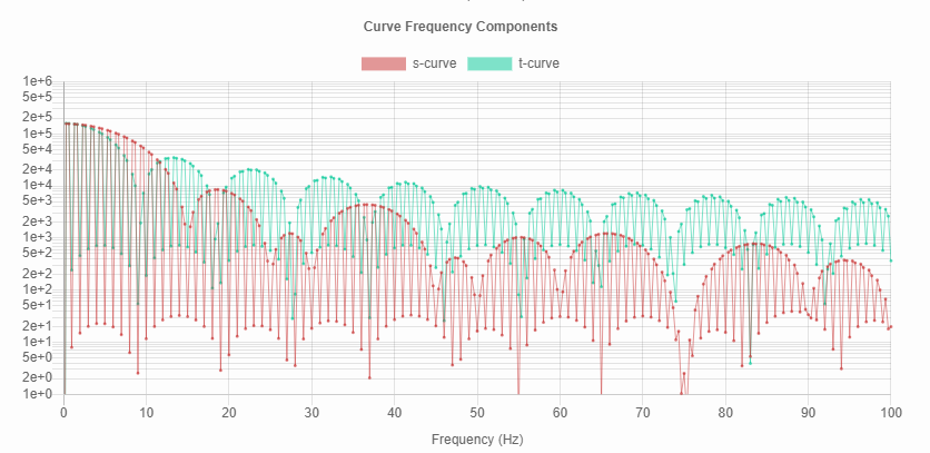
@dmbutyugin, speaking of parameter tuning, there's a tool here that lets you explore the effect of different velocity, acceleration, and jerk settings. Using J=775000, A=7000, and V=100 (your parameters from above), the frequency components are:
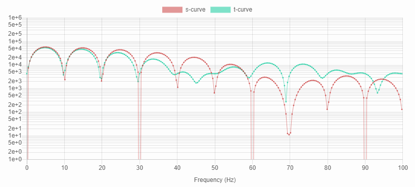
This shows that oscillations will be lower only for frequencies above 60Hz or so. But that seems reasonable for the mechanical resonant frequency of a rigid 3d printer.
 xenovacivus
on 27 Apr 2020
xenovacivus
on 27 Apr 2020
In case anyone is curious whether s-curves are "better" than trapezoidal curves - I've found they are in some situations. They reduce high-frequency excitations, but can increase the low frequency ones.
I'm sorry, but I am not sure what do your charts depict, frequency components of what? And why do they appear to have minima at frequencies of multiples of (1 / T_accel)?
However, your conclusion matches my previous analysis: naive S-Curve implementation works poorly when T_accel <= T_resonance and can excite more vibrations than trapezoid constant acceleration scheme. Typical 3D printers and 3D prints often operate in T_accel <= T_resonance case (as opposed to T_accel >> T_resonance case), so S-Curves show mixed results at best.
But a more advanced S-Curve planning might show better results. For example, 'scurve-smoothing' branch additionally has:
- jerk-limiting acceleration planning (this is really needed just to reduce the acceleration of the short moves)
- acceleration (spring) compensation, which, well, compensates for the springiness in the system during acceleration/deceleration.
All of the above combined together help to deal with the case when acceleration time is less than the resonance period.
Using J=775000, A=7000, and V=100 (your parameters from above), the frequency components are:
This shows that oscillations will be lower only for frequencies above 60Hz or so. But that seems reasonable for the mechanical resonant frequency of a rigid 3d printer.
I think your simulation does not account acceleration compensation (and smoothing, FWIW). I agree that this is a too high jerk value for 'pure' S-Curve acceleration profile. With a properly tuned acceleration compensation, it still works pretty well, as you can see from the pictures. And my printer has resonance frequencies around 47 Hz.
BTW, when acceleration compensation is enabled, the toolhead is commanded to follow the artificially constructed trajectory such that its _resulting_ trajectory should be of what it needs to be. So if you want to simulate acceleration compensation in your tool, instead of "position error between these blocks" you'd need to compare the position of the driven block vs the ideal position of that block, as opposed to the position of the driving block.
dmbutyugin
on 28 Apr 2020
The frequency plot is a Fourier-transform of the acceleration curve (which is representative of the forces on the system). It shows magnitudes of pure sine waves at the given frequencies necessary to reconstruct the acceleration curve. Using a curve with a trough at the resonant frequency of a system will minimize vibrations.
The periodicity in the frequency plot is characteristic of the transform of a rectangle function - a rectangle in the time domain becomes a sinc function in the frequency domain:
From Wikipedia:
Time Domain | Frequency Domain
:-------------------------:|:-------------------------:
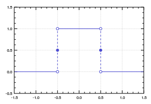 |
| 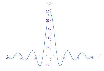
The frequency plots graph just the magnitude (absolute value), giving them that bouncing-ball appearance instead of the dampened sin wave appearance. The frequency of the sinc function depends on the width of the rectangle - the wider the rectangle, the more frequent the peaks/troughs become. Specifically, there will be minima at n/acceleration_time, where n is any integer.
That relationship is only strictly true for ideal trapezoidal profiles (and close to true for high-jerk s-curves). See the plots in my comment above - the first has lower jerk, and less alignment between the s-curve (red) and trapezoidal curve (green) excitation frequencies.
An yep, my simulation uses ideal S and T curves - it would be interesting to see the effect from incorporating smoothing and compensation. That might be a lot of work to match accurately though. Instead, I could feed in exact profiles captured from the step output of the controller (I've done this before with a logic analyzer & GRBL) - but I don't have the hardware to run klipper. Maybe there's someone out there with a cheap logic analyzer & klipper set up to run s-curves?
xenovacivus
on 28 Apr 2020
@xenovacivus thanks, since the chart was not described, I was not sure what was used to do a Fourier transform. This chart helps to get an idea of the acceleration qualitatively, but I am not 100% sure it is possible to use it for quantitative estimations (so the chart that shows the error between the two blocks is more informative for this purpose, in my opinion).
BTW
Instead, I could feed in exact profiles captured from the step output of the controller
Note that it is possible to run Klipper under Simulavr and dump pin changes with exact timing:
https://github.com/KevinOConnor/klipper/blob/master/docs/Debugging.md#using-simulavr-with-gtkwave
Maybe this can be of help?
dmbutyugin
on 28 Apr 2020
Alas, I still haven't had a chance to look at the recent enhancements and analysis done on s-curves. They do look really interesting.
Instead, I could feed in exact profiles captured from the step output of the controller
FYI, if you're interested in doing that type of analysis, you can get at the timing from a Klipper run in "batch mode". See docs/Debugging.md for information on generating a text file containing the micro-controller commands (ie, run klippy in batch mode and then translate the output to text). The schedule is encoded in the queue_step commands within the file (the format of the queue_step command is described briefly in docs/Code_Overview.md and docs/MCU_Commands.md).
-Kevin
KevinOConnor
on 29 Apr 2020
@dmbutyugin,
First, Nice work on top of @KevinOConnor. I've been struggling to get square corners since moving to Klipper, and this really helps.
For reference:
Piper2 CoreXY - (300mm x 300mm x 450mm) Fixed bed with a quad-gantry. Print head rises in Z-Axis
Z-Screws are T8*2
BMG dual gear clone Extruder (3:1 gear ratio)
850mm long Capricorn tubing.
At the BMG, I just started using compression fitting for the Bowden tube since the push-fittings have been getting destroyed due to high PA and retraction.
Klipper Main - PA=1.25 and it's still not enough. Retraction is between 7-9mm, depending on filament brand, print temp, and speed.
I ran the the ringing_tower.stl, prior to moving to your branch, 2x (model as provided then rotated at 45deg). I have ringing, although it is VERY hard to see since the bed is fixed to the frame. I was able measure the ringing, calculate the values, averaged the two X and Y values and just entered in the following:
[smooth_axis]
smooth_x: 0.0194
smooth_y: 0.0141
accel_comp_x: 0.000009
accel_comp_y: 0.000011
Printed the ringing_tower.stl again (just once) and WOW, no more rings.
Just re-ran the standard PA test and I'm able to FINALLY see a square corner with a PA = 0.88.
I have not added in my config yet:
[scurve]
acceleration_order: 4
min_jerk_limit_time: 0.02
In our opinion, would adding in the [scurve] options help to lower PA further?
Thanks, in advance, for your thoughts.
 jalanjarosz
on 9 May 2020
jalanjarosz
on 9 May 2020
Hello @dmbutyugin
Thank You very much for the hard work bringing us users closer to scurves.
After change to scurve-smoothing branch I have a problems with manual stepper movement.
Short moves (i think) are working ok but longer moves than ~20mm are not.
When i command a manual stepper to move=74 it moves for few mm and stop (and this isn't any over acceleration effect)
When got back to master branch the manual stepper i working ok again.
The log is from "before scurve-smoothing branch" to "after back to master"
klippy.log
 mwr666
on 11 May 2020
mwr666
on 11 May 2020
@mwr666 OK, thanks for reporting, I will take a look.
@jalanjarosz Glad that it worked for you. I suppose [scurve] will not likely to affect PA value much (though you can try, and if it does - please report back), but what it can do is put less stress on the extruder with the _same_ PA value. Worth a try, at least, and you can use max_jerk to further adjust this effect.
dmbutyugin
on 14 May 2020
@dmbutyugin
Has your code been integrated into Kevin's "master" branch? I don't get error messages about my config files now if I switch from "scurve-smoothing" to "master".
Gene
w1ebr
on 21 May 2020
@w1ebr no, it was not integrated. I think there was a regression (maybe intentional?) in Klipper a while ago already, which makes it silently ignore unknown options and sections, instead of throwing an error (you can check with a random gibberish option on master).
dmbutyugin
on 21 May 2020
I think there was a regression (maybe intentional?) in Klipper a while ago already, which makes it silently ignore unknown options and sections, instead of throwing an error
That was an error. Should be fixed now (commit 492cd3d9).
Thanks.
-Kevin
KevinOConnor
on 21 May 2020
Thank you, Kevin!
dmbutyugin
on 22 May 2020
@dmbutyugin
First of all - thanks for your work. It is FANTASTIC!
I've tried scurve-smoothing and scurve-c-combine-smoothpa branches. scurve-smoothing was not a success for me (probably due to wrong config). But scurve-c-combine-smoothpa was such a success!
I have a heavy (~ 3.5 kg) moving bed with resonance around 25 hz. And with s-curves i have NO SIGNS (!!!!!) of any vibrations even at speeds up to 150 with 6000 accelerations. I was impressed beyond belief. It was probably the most important upgrade of all. And I've upgraded almost everything.
What I find strange is that this super-important tool still has so little attention from the community.
Here are the things that I find significant obstacles for having a successful installation.
1) MAIN ONE. I can't find any main start-up document/overview. There are so many branches. Which is the right one to use?
2) Your master branch wasn't updated for too long. I believe it makes the impression that the project is dead for newcomers.
3) No issue tracking
4) All I've found for entrance is this thread. And it is very cluttered and unstructured.
5) I believe that some YouTube influencer would be glad to review your project and bring much attention/help/supporters here. I would especially recommend "CNC Kitchen" channel. His content is top quality and he already made some videos about vibrations https://www.youtube.com/watch?v=Ws1JfHl3Y0o.
I've done so many upgrades following his and others videos on youtube.
@KevinOConnor
Is it possible to integrate this work into main branch? I can firmly attest that quality improvement is BEYOND BELIEF (really!) and unmatched with any other firmware I used.
 vadsh
on 25 May 2020
vadsh
on 25 May 2020
@vadsh Thanks for your feedback! I am glad it worked in your case.
I've tried scurve-smoothing and scurve-c-combine-smoothpa branches. scurve-smoothing was not a success for me (probably due to wrong config). But scurve-c-combine-smoothpa was such a success!
That's pretty strange, I would expect that scurve-smoothing should work too. The problem is also that this one (or a variant of it) has more chances to be integrated into the mainline Klipper than scurve-c-combine-smoothpa branch, because it is less invasive and should be, at least theoretically, more robust. Now that you have this other branch configured and working, maybe you can try to follow the config conversion guide I posted earlier in this thread? If for whatever reason it will still not work, it would be great to understand in more details why.
What I find strange is that this super-important tool still has so little attention from the community.
I think it is being used by quite a few pioneers in the community. Others may not have apparent ringing, or be printing slowly for other reasons to improve the quality. An experimental nature of these branches may avert many folks as well, and I cannot blame them on this one (though I believe it should be pretty OK by now). However, I encourage everyone to share their success/failure stories, because it can give a general sense of how good or bad the feature is. I think it is also important to have some folks with a first-hand experience with this feature. Another reason to not push it too hard is the current perception of the feature (which, in all fairness, is not too far from the truth): it's a nice thing that may improve your prints, but it's a few days of fine-tuning down the drain (well, not completely down the drain if the tuning is successful in the end, and not a few days, but you get the idea).
Here are the things that I find significant obstacles for having a successful installation.
1. MAIN ONE. I can't find any main start-up document/overview. There are so many branches. Which is the right one to use?
There is one, though it is in a branch itself, which may defeat the purpose of it. Nonetheless, to re-iterate, scurve-smoothing is the currently suggested branch for general use.
2. Your master branch wasn't updated for too long. I believe it makes the impression that the project is dead for newcomers.
Yes, master branch isn't currently used for any real purpose. But the feature is not abandoned by any means.
3. No issue trackingTrue, though I sort of hijacked this issue tracker for issue reporting (and I encourage people to report issues here). Part of the problem is that my current schedule may not allow me to do everyday support continuously, especially if there will be issue reports that are not specific to S-Curves. Sorry. However, I do read issue reports here and try to fix bugs accordingly.
4. All I've found for entrance is this thread. And it is very cluttered and unstructured.
True. I am not sure if it can be somehow improved though (it is not designed for this kind of usecase).
5. I believe that some YouTube influencer would be glad to review your project and bring much attention/help/supporters here. I would especially recommend "CNC Kitchen" channel. His content is top quality and he already made some videos about vibrations https://www.youtube.com/watch?v=Ws1JfHl3Y0o.
   I've done so many upgrades following his and others videos on youtube.
That is an interesting idea. However, I am also not sure if I can pitch this feature to him or anybody else on YouTube, e.g. Thomas. I'm worried that the feature is not quite there yet, and if I approach them with 'hey, you know, there is this cool feature that lives in a fork of another somewhat experimental firmware, that may improve ringing on prints, would you like to test it and give it a review?', I would get a polite 'no, but thanks'. At the very least, this feature should become a part of the mainline Klipper, I suppose.
@KevinOConnor
Is it possible to integrate this work into main branch? I can firmly attest that quality improvement is BEYOND BELIEF (really!) and unmatched with any other firmware I used.
I am not Kevin, but let me try to shed some light into the current status of this feature and _my_ plans for future development. I think the current format gives a reasonable opportunity for early adopters to give it a try, share their experiences, and use it if they find it useful. Integrating the code into mainline signifies an important milestone and a certain commitment from the developers in the feature support and stability. Put it another way: once integrated and in use, it will be hard to remove/rework the offered feature set; even simple changes to the config parameters will be a hassle. There were some recent interesting discussions and developments in #2030, and I hope we will converge to a reasonable solution as a result that can be integrated into mainline Klipper. I actually think it will not be scurve-smoothing branch directly, but something along the lines, maybe still with S-Curves but different approach to acceleration compensation and smoothing, and hopefully more robust and easy to tune.
dmbutyugin
on 26 May 2020
@dmbutyugin Maybe you could put the recommended branch and a link to the proper getting started/calibration page in the master/Readme? That would be super helpful in terms of finding where to start, your calibration guide in this thread is somewhat difficult to find now that it has grown so large.
Thanks again for your work, I appreciate it a great deal.
slavedas
on 26 May 2020
@dmbutyugin I've been using the s-curve-exp/scurve-smoothing for some time now, and I love the results. Was able to increase acceleration to 7000 without any ringing. However, yesterday - I started to print a lithophane lamp - lots of small moves, curves, etc. - and the print got stuck at the same place twice.
I kept getting CommandError: Internal error on command:"G1"
Please see attached the log. Let me know if you need the gcode file as well. Or, if you want me to run some tests with the gcode file.
klippy.log.gz
I moved back to the master, and the printer printed the same gcode perfectly.
dushyantahuja
on 26 May 2020
Hello!
Writing just to give some feedback about the branch scurve-smoothing.
First some background:
I installed klipper on my printer at the start of this month, and I've been tweaking and experimenting with it in weekends.
I have a CR-10 v2, stock extruder, some issues in the X axis that can't fix right now and the stock board (2208 drivers in standalone mode). I found klipper because I was trying to make linear advance work in Marlin with these motor drivers and after finding it impossible I read that in Klipper worked without problem. And, indeed, it works like a charm.
So, I started to tweaking every aspect. After a lot of tests I reached the conclusion that in order to not have ringing in the X axis I had to print with accelerations below 1000. The Y axis wasn't that bad with ringing but because it's really heavy accelerations above 3000 made it to lose steps.
I found about S-curve in klipper repo seaching about ringing and acceleration. I had to read part of this issue to find the correct branch and the docs, not hard but not easy, I installed it and followed the basic configuration in the docs (one day down the drain)... and what a difference! I can print with accelerations of 3000 with no ringing and accelerations of 7000 are more than possible. Slow printing has also improved in quality and pressure advance seems to put less stress in the extruder and, somehow, to work better than before.
So yeah, @dmbutyugin this is marvellous, it works incredible well and I hope it gets added to base klipper at some time. From now on your branch will be the default in my printer. Thanks you very much for your work.
 Fenixin
on 26 May 2020
Fenixin
on 26 May 2020
Looks like the merge that brought in https://github.com/KevinOConnor/klipper/commit/492cd3d99fb40ef452c3ad50d07b14bc916d4548 fix broke the config detection.
I'm getting "Section 'smooth_axis' is not a valid config section" in the scurve-c-combine-smoothpa branch.
Update: Same goes for scurve-smoothing branch as well.
Nandox7
on 26 May 2020
@Nandox7 Actually, it is working as expected. smooth_axis is not a valid configuration section in scurve-c-combine-smoothpa branch. The two branches have different configuration format, and this section can be used on scurve-smoothing branch. You need to make sure you are using the right configuration on the right branch.
dmbutyugin
on 26 May 2020
@dmbutyugin I updterd my last comment as I went back here to read the past comments and moved to scurve-smoothing branch.
And was re-doing the tuning steps in: https://github.com/dmbutyugin/klipper/blob/scurve-smoothing/docs/S-Curve.md
Still I get the same error, even tried to reset my local repo and fetch all again.
 $ git branch -v
  master                       5afa5d3 docs: Fix typo in Contact.md
* s-curve-exp/scurve-smoothing 5afa5d3 docs: Fix typo in Contact.md
@Nandox7 I'm afraid you checked out the wrong revision. The commit 5afa5d3fbb2037f2c5ab1c93435bc9547de25894 is not part of scurve-smoothing branch (I did not merge it yet). It is possible that you merged some commits manually and are in the wrong repository state right now. To update, I suggest to use the following sequence:
$ git fetch s-curve-exp
$ git checkout -f s-curve-exp/scurve-smoothing
(not sure if it will recover your current repository state though).
dmbutyugin
on 26 May 2020
BTW, thanks everyone for their feedback! Additionally, if you successfully tuned and use scurve-smoothing branch, could you share which modules and options you've enabled and tuned? Did you enable [scurve] too, or just [smooth_axis] was sufficient? If you enabled [scurve], why? Did you tune accel_comp_x/y or just used the values suggested by default? If you've enabled [scurve], did you also tune max_jerk value?
Separately, as a heads-up, I reworked configuration options in scurve-smoothing branch a bit, and updated the tuning docs accordingly. In a nutshell, instead of having 2 separate sets of parameters smooth_x/y and accel_comp_x/y, there is now a single parameter for each axis: smoother_freq_x and smoother_freq_y (in Hz) in [smooth_axis] section. Additionally, now you do not have to provide min_jerk_limit_time parameter which has a default value of 0.02 (but you still can). The old configs still work (for now), but the code now computes smoother_freq_x/y from the old options as follows:
- if smoother_freq_? is set, it is used and smooth_? and accel_comp_? are ignored
- if smoother_freq_? is unset and accel_comp_? is set, smoother_freq_? is computed from accel_comp_? option
- otherwise, smoother_freq_? is computed from smooth_? option
In principle, you should not see any differences in prints in relation to this change (if you do notice, please let me know). In the future, smooth_x/y and accel_comp_x/y options will be disabled, so you can migrate your config now not waiting for that to happen (you can just put the results of your earlier measurements directly, or use one of the formulas):
- smoother_freq_x/y = 1 / (2 * pi * sqrt(accel_comp_x/y))
- smoother_freq_x/y = 2 / (3 * smooth_x/y)
The main motivation for these changes is to have simpler, more consistent API. These changes will also make it possible to use different smoothing functions with different smoothing times without you having to worry and recalculate the smoothing times when a change happens.
dmbutyugin
on 9 Jun 2020
CoreXY (corrected figures)
[printer]
max_accel: 4877
square_corner_velocity: 5.0
[extruder]
pressure_advance: 0.32
[smooth_axis]
smooth_x: 0.0084388
smooth_y: 0.0098039
accel_comp_x: 0.00000405869
accel_comp_y: 0.000005478
[scurve]
max_jerk: 317005
acceleration_order: 4
min_jerk_limit_time: 0.012658
Ender3
extruder]
pressure_advance: 0.24
[printer]
max_accel: 3000
max_accel_to_decel: 3000
[smooth_axis]
smooth_x: 0.0180
smooth_y: 0.0160
accel_comp_x: 0.00001857
accel_comp_y: 0.00001476
[scurve]
acceleration_order: 4
min_jerk_limit_time: 0.0241
BlackStump
on 9 Jun 2020
Hi!
After add
[smooth_axis]
smoother_freq_x: 85.1
smoother_freq_y: 69.8
in printer.cfg i have error:
Unhandled exception during connect
Traceback (most recent call last):
  File "/home/pi/klipper/klippy/klippy.py", line 136, in _connect
    self._read_config()
  File "/home/pi/klipper/klippy/klippy.py", line 129, in _read_config
    self.load_object(config, section_config.get_name(), None)
  File "/home/pi/klipper/klippy/klippy.py", line 118, in load_object
    self.objects[section] = init_func(config.getsection(section))
  File "/home/pi/klipper/klippy/extras/smooth_axis.py", line 116, in load_config
    return SmoothAxis(config)
  File "/home/pi/klipper/klippy/extras/smooth_axis.py", line 31, in __init__
    1. / (2. * math.pi * math.sqrt(accel_comp_x)),
ZeroDivisionError: float division by zero
 git branch -v
* (HEAD отделён на s-curve-exp/scurve-smoothing) f4f811f8 scurve: Use default value for min_jerk_limit_time when possible
  master                                         03fb7961 config: Use restart_method=cheetah in generic-fysetc-cheetah-v1.1.cfg
 mbgroot
on 11 Jun 2020
mbgroot
on 11 Jun 2020
@mbgroot Thanks for reporting! Should be fixed now.
dmbutyugin
on 11 Jun 2020
@mbgroot Thanks for reporting! Should be fixed now.
ок, ждёмс...
в основную ветку Кевин не планирует включать?
mbgroot
on 11 Jun 2020
@dushyantahuja Sorry, I only now got to look into the issue you ran into.
I kept getting CommandError: Internal error on command:"G1"
Please see attached the log. Let me know if you need the gcode file as well.
Could you please post your full GCode here? Unfortunately, a small excerpt from the logs was not sufficient to reproduce the issue.
dmbutyugin
on 11 Jun 2020
@mbgroot Thanks for reporting! Should be fixed now.
ок, ждёмс...
в основную ветку Кевин не планирует включать?
There are some discussions now to start with integration of some parts of it. It will either be smooth_axis or input_shaper from the other branch. I will also post a request here to give input_shaper combination a try.
dmbutyugin
on 11 Jun 2020
@dmbutyugin please find attached the gcode.
Avin-Lampshade1_LP_Model.gcode.gz
dushyantahuja
on 11 Jun 2020
Found a little bug.
I followed this guide: https://github.com/dmbutyugin/klipper/blob/scurve-smoothing/docs/S-Curve.md?fbclid=IwAR3HlG7fJ2nLGP7eoj_52ialOTVJDSPHicrUI_ewGF_9Qp-zajp0t2Ngd1w
 PerLangkjaer
on 11 Jun 2020
PerLangkjaer
on 11 Jun 2020
Found a little bug.
Already fixed:
https://github.com/dmbutyugin/klipper/commit/6b05bc28d39aed9f0d1fb373887ce0208cd8ec7c
mbgroot
on 12 Jun 2020
@dushyantahuja I managed to reproduce the bug, thanks. After some debugging, I reached a conclusion that the problem is insufficient precision of the current implementation of scurve integration with a smoother using doubles (with AO=6). I have not reached a point yet to either confidently fix the problem, or to conclude that the available precision of the doubles is insufficient for calculations in such a setup. As a good workaround, you can switch to acceleration_order = 4 for now, as this mode is significantly more numerically stable. Realistically, you should also not see any quality losses with this transition.
dmbutyugin
on 12 Jun 2020
Thanks - my printer has been off for that last few days. Hopefully, I'll be
able to get some experimentation done this weekend.
Dushyant Ahuja
On Fri, 12 Jun 2020 at 14:27, Dmitry Butyugin notifications@github.com
wrote:
@dushyantahuja https://github.com/dushyantahuja I managed to reproduce
the bug, thanks. After some debugging, I reached a conclusion that the
problem is insufficient precision of the current implementation of scurve
integration with a smoother using doubles (with AO=6). I have not reached a
point yet to either confidently fix the problem, or to conclude that the
available precision of the doubles is insufficient for calculations in such
a setup. As a good workaround, you can switch to acceleration_order = 4
for now, as this mode is significantly more numerically stable.
Realistically, you should also not see any quality losses with this
transition.—
You are receiving this because you were mentioned.
Reply to this email directly, view it on GitHub
https://github.com/KevinOConnor/klipper/issues/57#issuecomment-643270055,
or unsubscribe
https://github.com/notifications/unsubscribe-auth/ABQ6SCJJ4VKPC3WTZUTQLIDRWIUL3ANCNFSM4EIJ4S3Q
.
dushyantahuja
on 12 Jun 2020
Please note that I committed a change that drops the support of the old parameter options smooth_x, smooth_y, accel_comp_x and accel_comp_y. smoother_freq_x and smoother_freq_y (in Hz) should now be used. If you have frequencies available from the earlier measurements, you can just put the new values directly to printer.cfg config as is, for example,
[smooth_axis]
smoother_freq_x: 45
smoother_freq_y: 35
If you don't, or if you've specifically tuned acceleration compensation parameter, you can use one of the following formulae for conversion:
- smoother_freq_x/y = 1 / (2 * pi * sqrt(accel_comp_x/y))
- smoother_freq_x/y = 2 / (3 * smooth_x/y)
dmbutyugin
on 13 Jun 2020
Hi folks, if you have been successfully using scurve-smoothing branch, you could help further development by testing scurve-shaping branch. There is no tuning documentation for it available yet, but you can simply test a few configurations obtained from your current config. To check it out, run
$ git fetch s-curve-exp
$ git checkout s-curve-exp/scurve-shaping
Then convert your configuration for [smooth_axis] to
[input_shaper]
shaper_freq_x: ...
shaper_freq_y: ...
shaper_type: zv
where shaper_freq_x/y values are the same values as smoother_freq_x/y, and comment out [scurve] section if you have it. It would be great if you could print the ringing test with
TUNING_TOWER COMMAND=SET_VELOCITY_LIMIT PARAMETER=ACCEL START=1250 FACTOR=100 BAND=5 with the following shaper types:
- zv
- mzv
- zvd
- ei
and exactly the same shaper_freq_x/y parameters. If lacking time, just testing 'mzv' and 'ei' would be great. Then you could uncomment [scurve] section if you had it and repeat with the best shaper type. Please report your results here, which of the shapers work best, and if they are better or worse than the current [smooth_axis].
dmbutyugin
on 14 Jun 2020
BTW, thanks everyone for their feedback! Additionally, if you successfully tuned and use
scurve-smoothingbranch, could you share which modules and options you've enabled and tuned?
Modules and configs:
[smooth_axis]
smooth_x: 0.027777 # 2 / (3 * f_X)
smooth_y: 0.031595 # 2 / (3 * f_Y)
accel_comp_x: 0.000044 # 1 / (2 * π * f_X)^2
accel_comp_y: 0.000057 # 1 / (2 * π * f_Y)^2

# S-Curve acceleration and jerk-limiting motion planning.
[scurve]
acceleration_order: 4
min_jerk_limit_time: 0.042
Did you enable
[scurve]too, or just[smooth_axis]was sufficient? If you enabled[scurve], why? Did you tuneaccel_comp_x/yor just used the values suggested by default? If you've enabled[scurve], did you also tunemax_jerkvalue?
I did follow the tutorial and tuned accel_comp_x/y accordingly.
If I recall correcly smoothh_axis was more than enough quality-wise but I wanted to see how the printed moved with scurve, there was no quality issues just curiosity. After enabling it I left if on because it worked pretty well.
I did not tune max_jerk.
Fenixin
on 16 Jun 2020
Hi folks, if you have been successfully using
scurve-smoothingbranch, you could help further development by testingscurve-shapingbranch.
Hey!
I just tried this and printed the ringing tower with [scurve] commented out with my default configuration (I didn't change anyghing else) in: scurve-smoothing, scurve-shaping shaper: mzv and shaper: ei. I left [scurve] commented out in all the configs because it remove all the ringing from original scurve-smoothing and I wanted to compare with the new branches.
The print settings:
speed: 100mm/s
layer: 0.2mm
perimeters: 1
without top or bottom
I didn't know how to show you the results so I made some pictures and put it in a pdf. The ringing in all of them is very very subtle but I exaggerated it by changing the light angle:
Take into account that my X axis is kind of springy and really prone to ringing.
Some comments:
scuve-smoothingthe pictures lie a little bit here because this is the one with more ringing in all the axis.shaper: mzvthe ringing changes and a does funny things as acceleration increases in the x axis. In the Y there are a new high frequency ringing, I say high frequency because is quite a different from the scuve-smoothing one that you can see. This shaper provides very nice and squarish corners.
shaper: eithis is the shaper with less ringing. It's has a really nice finish but as acceleration increases the 90º corners get rounder and it's really obvious at the top of the ringing tower.
I think this branch gives more quality thatn scurve-smoothing at higher accelerations. And I personally prefere the mzv shaper because it seems to provide better corners. I hope that helps, if you need any more information just ask.
Fenixin
on 18 Jun 2020
@Fenixin Thanks, your feedback is really useful and helps a lot! For completeness, could you post your ringing frequencies for X ans Y axes? And do you remember, when did you update Git branches? The reason I'm asking is because yesterday I committed db7ecae330940a4aee1024b804fd29fd9ecfa1a0 to scurve-smoothing, and I'm just curious if that already made in your tests or not (though I do not expect this would change anything in quality really).
- shaper: ei this is the shaper with less ringing. It's has a really nice finish but as acceleration increases the 90º corners get rounder and it's really obvious at the top of the ringing tower.
FWIW, I've seen this effect too. The exact turnover point depends on the ringing frequency however - higher it is, the higher acceleration is tolerable/allowed. Technically, the same effect exists for mzv shaper and even for smooth-axis, but they use shorter windows than ei, and so they are susceptible to this effect much later at much higher accelerations.
In the Y there are a new high frequency ringing.
This is a really interesting effect. Would you be able to estimate its frequency using the same process, probably at higher accelerations where it is more visible? (I.e. measure the distance D between N high-frequency oscillations, and calculate the frequency as V * N / D) I want to try to understand if this is someting that mzv shaper creates (though it shouldn't), or if this is an existing resonance that it simply now left uncompensated.
dmbutyugin
on 18 Jun 2020
@Fenixin Thanks, your feedback is really useful and helps a lot! For completeness, could you post your ringing frequencies for X ans Y axes? And do you remember, when did you update Git branches? The reason I'm asking is because yesterday I committed db7ecae to
scurve-smoothing, and I'm just curious if that already made in your tests or not (though I do not expect this would change anything in quality really).
The test uses that commit. Just in case, the commits I used for the tests are:
commit 290b44267e0e16cbd44f13da1ea1db6f57630024 (HEAD, s-curve-exp/scurve-shapin g)
Author: Dmitry Butyugin
Date:   Mon Jun 15 20:19:37 2020 +0200

scurve-smoothing
commit db7ecae330940a4aee1024b804fd29fd9ecfa1a0 (HEAD -> scurve-smoothing, s-curve-exp/scurve-smoothing)
Author: Dmitry Butyugin
Date:   Wed Jun 17 01:05:56 2020 +0200
My frequencies are:
[input_shaper]
shaper_freq_x: 24
shaper_freq_y: 21.1
And, just in case it's useful, my configuration file (as used in the mzv test):
This is a really interesting effect. Would you be able to estimate its frequency using the same process, probably at higher accelerations where it is more visible? (I.e. measure the distance D between N high-frequency oscillations, and calculate the frequency as V * N / D) I want to try to understand if this is someting that
mzvshaper creates (though it shouldn't), or if this is an existing resonance that it simply now left uncompensated.
Sure! 3 oscillations have approximately 3.1mm and that gives us 97Hz.
Fenixin
on 18 Jun 2020
@Fenixin Thanks! And what about the remaining oscillations on Y axis with, say, scurve-smoothing (as it's probably easier to measure them)? Are they still ~21.1 Hz?
dmbutyugin
on 18 Jun 2020
@dmbutyugin it looks like the frequency has increased to around 30Hz but, honestly, It's quite hard to measure. I should probably adjust this again.
This change in frequency could be related to the change in temperture. The printer is in pretty bad insulated room and the weather has changed drastically around here. I think when I adjusted it it was like 15ºC and the same room is around 30ºC right now.
Or, another posibility, i messed up measuring it the first time.
Anyway, this weekend I want to spend some time updating some parts of the printer, after that I can tune and fine tune the frequencies and run this tests again.
Fenixin
on 18 Jun 2020
@Fenixin Yes, it would be good to double-check the frequencies, and test using the right ones.
Separately, I tend to think that MZV shaper does not create that high-frequency ringing itself: in that configuration it has pulses at ~0.021 sec distances, which corresponds to 64 Hz frequency. It is more likely that the printer has that resonance frequency too, and it just does not compensate well enough for it. But it is still strange, because EI shaper should compensate for such high-frequency oscillations not much better either. But please do try the test again with correct frequencies for X and Y axes.
dmbutyugin
on 19 Jun 2020
@dushyantahuja BTW, I think I've fixed a numerical stability issue in scurve-smoothing branch that manifested in your lithopane lamp - simulation using your config fully passes on it now. Thanks for reporting! It was indeed a bug.
dmbutyugin
on 19 Jun 2020
@dmbutyugin May I Ask; I would like to participate and give you feedback but for some reason I cant get your branch working. I use DWC2, can control the temp of the nozzle, but no Homing of any axes at all.
I guess DWC2 isn't yet supported? I have used another branch of you with it before. Any Idea?
I think I understand what might cause that error:
My printer.cfg contains
[input_shaper]
shaper_freq_x: ...
shaper_freq_y: ...
shaper_type: zv
This seems to output an error. Not sure whats wrong. If I have this section in my config the printer wont respond over DWC2.
 neophrema
on 19 Jun 2020
neophrema
on 19 Jun 2020
@neophrema Which branch did you try, scurve-smoothing or scurve-shaping? [input_shaper] is for the latter. Also, in the snippet of the config you have commented out shaper_freq_x and shaper_freq_y, but they are required parameters.
Separately, I have not tested the branch with DWC2 and cannot comment on how it does (not) work with it. Maybe there are other people who use one of the branches with DWC2?
dmbutyugin
on 19 Jun 2020
I used s-curve-shaping; Yes I had commented it out since I wanted to get the values due to testing; I thought it might be interesting that this doesn''t work, maybe others have the same braintwist, not sure, since it's late. I guess its not a DWC2 Issue, I mean you also confirmed the freqs are needed.
May I Ask, is there a possibility to debug, see an error thrown?
I didn't receive any error in the klipper log, maybe it's feasible to throw an error out there? Sorry, just a thought regarding new users like me ;)
neophrema
on 19 Jun 2020
@neophrema Logs, including errors, should be available in /tmp/klippy.log on RaspberryPi.
Edit: BTW, shaper_freq_x and shaper_freq_y are needed to enable shaping for the given axis. But if they are not provided, they default to 0, which disables input shaping for the corresponding axis. So it should not be a reason for errors per se. It is more likely that there is some compatibility issue with DWC2. This was never tested by me and may very well not work, especially since DWC2 patches modify Klipper code. I would suggest to try a clean scurve-shaping branch.
@w1ebr I haven't seen such effect. But note that the tuning tower command from the instructions uses BAND, so it will increase the acceleration every 5 mm. If that does not happen - that is very strange.
dmbutyugin
on 20 Jun 2020
I was using the wrong test STL. Accel_test_v4 has a couple of sine wave pulses in it so it printed perfectly every time.
w1ebr
on 20 Jun 2020
@dmbutyugin The issue was that nothing regarding this segment [input_shaper] was thrown out in the klippy.log. I was stuck and had to trial and error to find that it doesn't want the shaper_freq to be commented out.
It can indeed be that DWC2 has an Issue with this, but I personally don't think so. It was strange cause I could alter the Bed/Hotend temps but no movement, so it wasn't a complete crash.
But you might be right. Thanks for investigating.
My printer is in pieces right now, as soon as I get a delivery i'll be back on track and reporting regarding your questions (new branch)
neophrema
on 21 Jun 2020
@Fenixin Did you have a chance to double-check the resonance frequencies for your printer and re-run the tests, maybe?
dmbutyugin
on 22 Jun 2020
@dmbutyugin, just had enough time during the weekend to do almost all the updates but not to print any tests. I hope to be able to do the testing during this week because next weekend is going to be impossible.
If I find the time I'm going to start from scratch doing a scurve tuning using the documentation in scurve-smoothing. Is there any other documentation to follow? Do you want me to do anything special?
Fenixin
on 22 Jun 2020
@Fenixin Just running the basic measurements of ringing frequencies for X and Y axes would be sufficient, I think doing the full tuning is not necessary. I'd be curious to see if you measure the old 24 Hz and 21.1 Hz frequencies, or values closer to 30 Hz (or whichever it will be now). Then maybe you could print 2 test prints using scurve-smoothing and scurve-shaping branches as you did earlier, but with corrected frequencies and share your results. It's pretty much the same process as basic measurements, with pressure advance disabled and TUNING_TOWER COMMAND=SET_VELOCITY_LIMIT PARAMETER=ACCEL START=1250 FACTOR=100 BAND=5 commaned, but with [smooth_axis] or [input_shaper] sections added and no [scurve] section (comment it out). Thank you in advance!
dmbutyugin
on 23 Jun 2020
I thought I'd give S-curve a try so installed the scurve-c-combine-smoothpa branch with the current klipper master. After figuring out the acceleration_order and min_jerk_limit_time values things looked really good on the test print. I then set up PA and reran the print and it looked great. However any time I try to print something that doesn't have a large straight surface I get severe under extrusion - even if I expressly set PA back to 0.0. Printing the same STL using the normal branch prints fine, except for the ringing, so it's not a problem with the STL or extruder. I get the same under extrusion if I halve the size of the ringing test STL as well. The PA values are similar for both 'normal' and s-curve at 0.0551 vs. 0.0454 respectively.
I did a test print using the larger PA value from the 'normal' branch and the print was virtually unchanged.
Is there something else I can do to narrow down the problem as I'd really like to be able to hit the higher speeds along with improved print quality on my BLV mgn Cube. I'm using an SKR PRO V1.1 and TMC2225 drivers in case that somehow makes a difference.
 tgmorris99
on 23 Jun 2020
tgmorris99
on 23 Jun 2020
@tgmorris99 I would suggest you to use scurve-smoothing branch, which is a currently recommended branch, and is in general more robust than that one (though it is unlikely to fix this problem with underextrusion). Note that you don't really have to repeat the tuning process, you can simply use your already measured values and put in the config as described in the instructions, but make sure not to mix X and Y axis resonance frequencies (note that you should take the value from Y axis of the test print and put it as X axis parameter and vice versa, the updated test model has letter hints).
Separately, what may help is trying to tune max jerk value. Could you try following the instructions there, try to put hopefully increased max_jerk value into the config, and see if that helps?
dmbutyugin
on 23 Jun 2020
I've switched to the recommended branch and the ringing tower test prints great after adding in the new PA value (0.0488) but the smaller test print is still under extruded. I'll try some fine tuning a bit later but the print is currently using a max_jerk of 1500000 as I've seen that posted on the discord.
tgmorris99
on 23 Jun 2020
Hmm, if max_jerk is truly 1500000, it as the higher end of its values. I would suggest to try the following: completely comment out [scurve] section and try printing with just [smooth_axis] enabled. And another thing - re-enable [scurve] section, but put a smaller max_jerk value, for instance 300000. The thing is, your problem appears to be pretty rare (not sure if anybody else ran into this issue), but given that the master branch prints fine with the same settings, it is certainly related to [smooth_axis] or [scurve] kinematics. So I am trying to help debugging the problem by trying different combinations that hopefully will allow us to identify what is causing it.
Edit: you can also double-check your other printing parameters: that the printing temperature you are using is what is suggested for your filament, that you are not exceeding volumetric printing speed of your hotend (I wouldn't exceed 8-10 mm^3/sec on v6 and alike; BTW, which hotend do you use?), and that the thermistor didn't get loose or broken off. Honestly, it's not very likely, but if something like that happens, it can produce strange and surprising effects.
dmbutyugin
on 24 Jun 2020
After much more testing and totally reverting back to a clean install it turns out the issue was related to the temperature being too high. Doesn't really explain why it was working on larger, longer, runs though. I'm doing some more test prints and will likely redo the calibration but using the original numbers with acceleration of 5K looks promising. I tried 7K acceleration but it resulted in visible ringing.
The other thing I notice is that both 3K & 5K acceleration have what looks like salmon skin or wood grain pattern but this is on a corexy so I'll need to figure out what's going on there.
tgmorris99
on 24 Jun 2020
@tgmorris99 I see in your config you are using TMC2208 but you mention you are using TMC2225, I do not know if they are configured the same. btw TMC,s website makes no mention of TMC2225
You would need to check the TMC datasheet to check if the parameters are the same. I suspect that is where your problem lies as I use a SKR Pro V1.1 with TMC2208's without issue and I have done multiple test prints with most of @dmbutyugin branches
BlackStump
on 24 Jun 2020
The TMC2225 is a direct replacement for the TMC2208 according to the BigTreeTech TMC2225 User Manual
Firmware with TMC2208 settings
The TMC2225 UART mode can be used by directly replacing
TMC2225 on the motherboard using TMC2208 UART mode.
I've got some more testing to do but it appears that the problem was related to extrusion temperature - though I don't understand the mechanism where it only seemed to impact smaller prints.
tgmorris99
on 24 Jun 2020
The TMC2225 is a direct replacement for the TMC2208 according to the BigTreeTech TMC2225 User Manual
Firmware with TMC2208 settings
The TMC2225 UART mode can be used by directly replacing
TMC2225 on the motherboard using TMC2208 UART mode.I've got some more testing to do but it appears that the problem was related to extrusion temperature - though I don't understand the mechanism where it only seemed to impact smaller prints.
@tgmorris99 I've seen this before. More rapid retractions pulls molten filament up into the heatbreak because it's retracting more often with less of the molten filament being pushed out the hot end before it needs to retract again.
slavedas
on 24 Jun 2020
The TMC2225 is a direct replacement for the TMC2208 according to the BigTreeTech TMC2225 User Manual
Firmware with TMC2208 settings
The TMC2225 UART mode can be used by directly replacing
TMC2225 on the motherboard using TMC2208 UART mode.I've got some more testing to do but it appears that the problem was related to extrusion temperature - though I don't understand the mechanism where it only seemed to impact smaller prints.
I think @BlackStump meant the salmon skin problem; you should indeed double-check that. Note that Klipper may, modify more internal Trinamic registers than Marlin does (or modify them differently) - so even if TMC2225 works as a direct replacement of TMC2208 in Marlin, it may not be the case with Klipper.
The underextrusion problem could be related to what @slavedas said; and in general, short moves are slower because the toolhead has less space to accelerate and decelerate - so the filament has more time to "bake" in the too hot hotend, which may damage the filament's polymer structure after some amount of time.
dmbutyugin
on 24 Jun 2020
There's been a lot of great progress on this topic over the last 2.5 years. However, I think this github issue has become too unwieldy. I'm thinking of closing it in favor of opening new issues with updated topics.
@dmbutyugin - what would you think about opening up tickets for "input shaping", "input smoothing", "adaptive acceleration", along with tickets for any other development you feel is currently interesting?
At this point, I feel pretty confident that the initial software associated with this issue (simple "bezier s-curve" on unmodified trapezoid generator) does not provide a good solution. Similarly, I feel pretty confident that my early attempts at smoothing in PR #2030 is also not a good solution. So, I think it may be beneficial to close these github issues to better focus the conversation on the newer solutions.
-Kevin
KevinOConnor
on 25 Jun 2020
@KevinOConnor I do not really mind, if you prefer it that way
However, I think this github issue has become too unwieldy.
I guess that's largely true.
I think the only benefit of the current #57 issue is that it is a single place, and in the new setup people may get confused as to where to report problems. To be fair, right now there may be some confusion too.
@dmbutyugin - what would you think about opening up tickets for "input shaping", "input smoothing", "adaptive acceleration", along with tickets for any other development you feel is currently interesting?
I can do that. Ironically, it is likely that one of the new tickets will be about S-Curve acceleration :) But we'd need some comparative assessment whether it improves anything over, say, simpler input shaping or not - even if under certain conditions. Hopefully, if the latter gets integrated into the mainline, it will be easier to do that.
dmbutyugin
on 26 Jun 2020
@dmbutyugin, Hello again!
I don't really know the reason for the change but I measured the new resonance frequencies in my printer and they have changed. The new frequencies are:
X axis: 27,3986244182194
Y axis: 31,1828690076847
Old frequencies:
X axis: 24
Y axis: 21
In the attached pdf you can see the results of the test scurve-shaping-medidas-nuevas.pdf. I have included pictures of the measurement of the frequencies, the test didn't end because the Y axis started to skip steps.
Some observations:
- The ~100hz frequency in the Y axis is there from the start. So is not a problem with any of the branches. This brings a question, can these branches compensate two resonance frequencies in the same axis?
- Without doubt, the best branch reducing ringing is
scurve-shapingwithshaper: ie, at least from tested ones. The corners are rounder at very high accelerations but if you stay in the safe side the results are stunning. - All these test were made with this config file changing needed parameters when changing branch:
printer.cfg.txt - Without pressure advance (the first test I did and reported here was with pressure advance on) there is something funny going on in
scurve-smoothing, everytime there is a change in layer (a change in z coordinate) a small blob generates when the acceleration is high enough. There is a picture of this in the pdf file. It could be the object moving by itself from the high accelerations and the fact that is one shell thick. I could test and watch this next week.
I hope this helps. From now on I'm going to use scurve-shaping with shaper: ie with accelerations of 3000~4000. If you have any questions just ask.
Fenixin
on 26 Jun 2020
* The ~100hz frequency in the Y axis is there from the start. So is not a problem with any of the branches. This brings a question, can these branches compensate two resonance frequencies in the same axis?
Incidentally, yes. You can use 'EI' shaper tuned for 33 Hz for Y axis (note that it reduces vibrations in the wider range of frequencies; at shaper_freq_y = 33 it reduces vibrations from ~27 Hz to ~40 Hz and then around 100 Hz; different lines in the plot are for different damping ratios _of the printer_):

* Without doubt, the best branch reducing ringing is `scurve-shaping` with `shaper: ie`, at least from tested ones. The corners are rounder at very high accelerations but if you stay in the safe side the results are stunning.
With 31 Hz you were already close, so it makes sense. BTW, X axis seems to have some remaining vibrations at high accel even with EI shaper. You can try to measure the frequency of those using an existing print. If their frequency is the same ~27-28 Hz, there's nothing else you need to do.
* Without pressure advance (the first test I did and reported here was with pressure advance on) there is something funny going on in `scurve-smoothing`, everytime there is a change in layer (a change in z coordinate) a small blob generates when the acceleration is high enough. There is a picture of this in the pdf file. It could be the object moving by itself from the high accelerations and the fact that is one shell thick. I could test and watch this next week.
This is why it is recommended to print the test using smooth vase mode. Generally, I guess it's fine.
From now on I'm going to use
scurve-shapingwithshaper: iewith accelerations of 3000~4000.
It makes sense. The general direction where this is going is to recommend and use scurve-shaping branch. I just need to write some tuning docs. But you have already tuned it.
dmbutyugin
on 26 Jun 2020
With 31 Hz you were already close, so it makes sense. BTW, X axis seems to have some remaining vibrations at high accel even with EI shaper. You can try to measure the frequency of those using an existing print. If their frequency is the same ~27-28 Hz, there's nothing else you need to do.
My X axis is in pretty bad shape, it vibrates A LOT. AFAIK the problem is the belt tensioner, it's really springy and makes the whole axis act like spring. I want to change X belt tensioner for something that is more stable but, funny thing, if I change it the printer won't fit inside the current enclusure and right now there is no other place for it, so it's going to stay like that for some time until I find a new place for the printer or I build a new enclosure.
The frequency is more or less the same, around 27Hz, the fix has to come from hardware, there is no more to do in software.
Again, thanks for your work, I will follow this or any issue that you open to be up to date.
Fenixin
on 26 Jun 2020
@Fenixin
The frequency is more or less the same, around 27Hz, the fix has to come from hardware, there is no more to do in software.
OK, then it makes sense only to adjust the Y axis frequency to 33 Hz with EI shaper. Let me know if that reduces high-frequency vibrations (though AFAICT, high-frequency vibrations are already smaller with EI shaper at 31 Hz).
dmbutyugin
on 26 Jun 2020
OK, then it makes sense only to adjust the Y axis frequency to 33 Hz with EI shaper. Let me know if that reduces high-frequency vibrations (though AFAICT, high-frequency vibrations are already smaller with EI shaper at 31 Hz).
Just printed the test again with the Y axis to 33Hz. There seems to be a very subtle improvement in one of the ripples but is something so faint that I'm not sure it's really something or just my imagination.
This is going to be my default branch/config. Thanks again for your work
Fenixin
on 1 Jul 2020
@dmbutyugin is manual_stepper using scurve step generation. I seem to be getting timeout on slow manual_stepper moves.
 ehtnevets
on 5 Jul 2020
ehtnevets
on 5 Jul 2020
Small bug on @dmbutyugin s-curve fork manual_stepper.py,
self.trapq_append(self.trapq, self.next_cmd_time, 2,
accel_t, 0., accel_t, 0., accel_t, 0., accel_t,
cp, 0., 0., axis_r, 0., 0.,
0., cruise_v, accel, accel)
should be
self.trapq_append(self.trapq, self.next_cmd_time, 2,
accel_t, 0., accel_t,
cruise_t, # was 0
accel_t, 0., accel_t,
cp, 0., 0.,
axis_r, 0., 0.,
0., cruise_v,
accel, accel)
I need to check this because i had some issues with manual stepper also with this branch
mwr666
on 5 Jul 2020
@ehtnevets It uses some common parts, but sticks with AO=2. But yes, you are right, this seems indeed like a root cause of the bug. I pushed a fix to scurve-smoothing, could you check that it's working now?
dmbutyugin
on 6 Jul 2020
Separately, I have updated the tuning instructions in scurve-shaping branch, which is now a suggested branch for use. If you are using a different branch, please switch to this one. If you have been using scurve-smoothing branch, the transition can be as simple as switching the branch in git and converting the config
[smooth_axis]
shaper_freq_x: ...
shaper_freq_y: ...
instead to
[input_shaper]
shaper_freq_x: ...
shaper_freq_y: ...
which should give you similar results.
You can also try to follow the tuning guide at your convenience.
If you have issues with input shapers specifically, you can use #3025 ticket to report them.
dmbutyugin
on 6 Jul 2020
This comment/conversation came up regarding the tuning process for pressure advance but is wroth to ask here as well.
Does using the bed mesh after setting the tuning params will disable them? That seems to be the case for pressure advance and as the commands are the same I'm checking it here. Thanks
Nandox7
on 6 Jul 2020
@Nandox7, I guess it depends on how you try to enable the bed mesh. Could you post the entire list of commands that you are trying to execute? And the config you start with?
dmbutyugin
on 7 Jul 2020
So in the gcode that is generated for the tower from the slicer it will have
G28 W ; home all without mesh bed level
G80 ; mesh bed leveling
And this is what is defined in klipper for G80
[gcode_macro G80]
gcode:
 BED_MESH_CALIBRATE
 G1 X0 Y0 Z10 F3000
In terms of commands I simply use the ones mentioned in the tuning guide.
Nandox7
on 7 Jul 2020
@Nandox7 Generally speaking, no, AFAIK BED_MESH_CALIBRATE should not affect it, unless, of course, SAVE_CONFIG or RESTART is issued afterwards. What I'm not 100% sure about is how it will interact with TUNING_TOWER - but you can monitor the messages at the start of and throughout the print. Also for many commands you can run them without parameters and they will simply print the current state. So you can add them to your gcode after G80 (or as a part of that macro), e.g.:
G28
SET_PRESSURE_ADVANCE
SET_INPUT_SHAPER
SET_SCURVE
....
and check their output in the Octoprint console.
dmbutyugin
on 7 Jul 2020
Thanks everyone! The input_shaper module has been merged, and I think we've made a lot of great progress since this issue was originally created. I'm going to close this issue in order to focus the conversation on the newer issues #3025, #3026, and #3027.
-Kevin
KevinOConnor
on 20 Jul 2020
Related issues
KevinOConnor
·
5Comments
 jannoke
·
3Comments
jannoke
·
3Comments
 aegelsky
·
3Comments
aegelsky
·
3Comments
 amaximchuk
·
6Comments
amaximchuk
·
6Comments
 krpepe
·
5Comments
krpepe
·
5Comments
Most helpful comment
Separately, note that improving quality does not always mean printing slower. Of course, YMMV, but I thought about sharing an example of 3D benchy printed on master Klipper branch and using this S-Curve branch. The model sliced at 100 mm/sec speed (50 mm/sec for external perimeters), 0.2 mm layer. I printed it on master Klipper branch with max_accel = 3000, and then exactly the same GCode on scurve-smoothing branch with parameters tuned for my printer, and specifically max_jerk = 775000 and max_accel = 7000 (essentially no limit). The print on scurve-smoothing branch finished a few seconds faster than on the master branch. The results are the following: |
| |
| |
| |
|
| master | scurve-smoothig |
|----------|------------------------|
|
|
The quality on master branch is not bad at all. But one can clearly see some ringing around 90 degrees corners, e.g. on a cabin and the hole for the anchor chain. Scurve-smoothing branch print does not show ringing, and it printed the same amount of time (even a few seconds faster). Again, this does not mean that one can always achieve such results, but just to show that tuning the parameters can reduce the time penalty in general.