Do you plan to add support for LCD + encoder? Or will control always be done through octoprint?
 mhv-shared
All 256 comments
Do you plan to add support for LCD + encoder? Or will control always be done through octoprint?
My personal opinion is that new hardware designs would be better off talking directly to the host and use octoprint. For existing hardware, I think it would make sense for Klipper to support common lcd panels.
I don't have an immediate plan to add support. Contributions are welcome.
-Kevin
 KevinOConnor
on 17 Apr 2017
KevinOConnor
on 17 Apr 2017
Please, I would like to contribute with this - just to have very simple functions (like show status, homing, change filament commands, etc) and use the card reader. What do you recommend as a starting point? I do know the (very) basics but not sure where to start besides your documentation.
 brunofporto
on 31 Jul 2017
brunofporto
on 31 Jul 2017
On Mon, Jul 31, 2017 at 06:00:03PM +0000, brunofporto wrote:
Please, I would like to contribute with this - just to have very simple functions (like show status, homing, change filament commands, etc) and use the card reader. What do you recommend as a starting point? I do know the (very) basics but not sure where to start besides your documentation.
What hardware did you wish to support? If this is for basic lcd
support, then what I would do is add a pass-through mechanism in the
micro-controller code that would allow the host code to bit-burst out
data to the lcd controller. Then the python host code would need to
contain the logic necessary to draw the screen.
See the src/spicmds.c code for an example of how this was done to
communicate with the ad5206 chip.
-Kevin
KevinOConnor
on 1 Aug 2017
Thank you!
I have the http://reprap.org/wiki/RepRapDiscount_Full_Graphic_Smart_Controller connected to the RAMPS.
The src/spicmds.c example should solve the data sent to the LCD part witch is already nice.
What about the other way around? Reading the encoder and push button to execute simple commands like change filament, move axys, etc.?
Would be simpler to run this code directly from the MC or would be interesting the have MC sending messages back to the host and process the request there?
Other interesting enhancement would become able to read the SD card :D
brunofporto
on 2 Aug 2017
Wouldn't it be better to attach the LCD to the RPi?
Since the host benefits from running Octoprint + klipper,I added a cheap $9 ILI9340C lcd with TouchUI plugin enabled. https://learn.adafruit.com/3-dot-5-pitft-octoprint-rig/overview
Though I do understand that one of the primary goals of Klipper is drop-in replacement.
 ghost
on 2 Aug 2017
ghost
on 2 Aug 2017
TunaLatte... I can't argue with that.... Even the 3.5" LCD TFT is no more than US$ 16....
brunofporto
on 2 Aug 2017
On Tue, Aug 01, 2017 at 03:18:40PM -0700, Bruno Porto wrote:
Thank you!
I have the http://reprap.org/wiki/RepRapDiscount_Full_Graphic_Smart_Controller connected to the RAMPS.
This should solve the data sent to the LCD part witch is already nice. What about the encoder and simpler commands (change filament, move axys, etc.)? Would be simpler to run them directly from the MC?
Klipper is designed so that all the kinematics and timing is done in
the host software. So, it would not work well to attempt to process
general user commands solely in the micro-controller. However, it
should not be a problem for the micro-controller to pass them back to
the host for processing - the comms are fast enough that a button
press could be sent and a full screen draw returned faster than a
human eye could detect.
-Kevin
KevinOConnor
on 4 Aug 2017
On Wed, Aug 02, 2017 at 03:51:52AM -0700, TunaLatte wrote:
Wouldn't it be better to attach the LCD to the RPi?
I'd certainly recommend that for new hardware designs. I don't have
any objections should someone wish to get existing hardware
functioning, however.
-Kevin
KevinOConnor
on 4 Aug 2017
I see now, it made sense to me at first since in my case I had to add a host (rpi) to my existing setup due to the nature of how klipper works, same story with LCD.
Would be also good to have MCU stats/debug info (like klippy log info) running in realtime on LCD (without host communication) as preliminary support for MCU LCD.
ghost
on 4 Aug 2017
is there any CPU concern to run Klipper, a browser with octoprint and driver for one of those : https://www.waveshare.com/3.2inch-rpi-lcd-b.htm ?
Edit :
Scratch that SPI screen, might be better off using an HDMI one. Should add less stress on the CPU.
 andreq
on 21 Nov 2017
andreq
on 21 Nov 2017
On Tue, Nov 21, 2017 at 09:05:32PM +0000, Andre Q. wrote:
is there any CPU concern to run Klipper, a browser with octoprint and driver for one of those : https://www.waveshare.com/3.2inch-rpi-lcd-b.htm ?
An RPi3 has a ton of available CPU power. I'm not familiar with that
particular hardware, but I doubt it would be an issue.
-Kevin
KevinOConnor
on 21 Nov 2017
I have been looking at using a Nextion display recently with Marlin and just came across your firmware. I like what you have done a lot and think i will give it a try but was wondering if you think a Nextion display would be difficult to integrate? as even though i do use octoprint i still like to have local control of my machines.
 Bobblejot
on 2 Dec 2017
Bobblejot
on 2 Dec 2017
I dont think for the nextion any integration is needed at all, it just works as a display for the pi and thereby should work with octoprint just fine.
 lenne0815
on 3 Dec 2017
lenne0815
on 3 Dec 2017
The Nextions are small HMI panels so you need to upload your own interface designs to them. I have plenty of displays i could just use with Octoprint and the Pi directly but i do like the idea of just a custom solution for my own machine, Plus i have a 4.3" Nextion sitting doing nothing that i want to play with :-)
Bobblejot
on 3 Dec 2017
RepRap Full Graphic Controller is the worst option due to slow communication. Now Marlin 2 32bit has trouble with it.
 rafaljot
on 4 Dec 2017
rafaljot
on 4 Dec 2017
I think we should more concentrate on getting UI connected to Rassberry Pi, on it even a slow LCD won't be any problem (just run the UI in separate thread).
 dragonnn
on 4 Dec 2017
dragonnn
on 4 Dec 2017
Exactly
rafaljot
on 4 Dec 2017
Hi, I'm new to Klipper and it seems to fit ideal to my own plans. In fact, from what I read in the forum, most things are already solved by you, even problems I didn't think of, really nice, Kevin...
now on the topic:
I don't really get why everyone wants some LCD. I bet everyone here has a Smartphone?
Simply take the touch UI plugin of octoprint and use it. It couldn't get better.
Touch UI is a lot faster and much more convenient than scrolling through menus and clicking.
This also has the advantage to be able to take it with you, say when cooking coffee or on the toilet (or use another device). And you can see the printers webcam...
Full control everywhere.
Additionally, many people have older smartphones laying around and doing nothing.
Just install one of them on the printer. In fact I do this since I have octoprint on my printer.
You can even use a big tablet.
Additionally an old monitor and any kind of keyboard or mouse can be used.
On linux you may find solutions to run a web browser fullscreen (easiest will be using F11).
Do you need any more?
I do not think it is worth to invest time in simple LCD screens. I have two laying around and didn't have any need for them for years.
 hg42
on 10 Dec 2017
hg42
on 10 Dec 2017
^This, so much!
I plan on using this over the RPI https://shop.pimoroni.com/products/hyperpixel and from my initial test, it's gonna work great as a replacement from my old Graphical LCD running Marlin. One could use a cheaper screen sold in many size from China.
I'm not sure there should be much time invested in getting those old graphical/character LCD running on the arduino anymore. It will take a good chunk of the processing power for sub-part user experience.
The only thing I'll be missing (for now) is a physical rotary encoder/buttons with some macro, but it might be from many years of using the graphical LCD ;)
Edit : Btw, there's a script to launch TouchUI at boot time : https://github.com/BillyBlaze/OctoPrint-TouchUI-autostart
andreq
on 11 Dec 2017
If this is for basic lcd support, then what I would do is add a pass-through mechanism in the micro-controller code that would allow the host code to bit-burst out data to the lcd controller. See the src/spicmds.c code for an example of how this was done to communicate with the ad5206 chip.
Not all displays use a SPI protocol. A lot of printers use the RepRapDiscountFullGraphicsSmartController, for example, which uses a pain-in-the-ass non-SPI protocol that is extremely sensitive to timing.
Perhaps this could be solved by defining a command called "send x bytes to LCD" and the firmware would know how how to send bytes to the specific type of LCD that was configured, either using SPI, or something else, as in the case of the RepRapDiscountFullGraphicsSmartController.
 marcio-ao
on 8 Jan 2018
marcio-ao
on 8 Jan 2018
The biggest downside I see in having host send raw bytes is that the graphics protocol would need to be re-implemented on the host side, which is Python. I can see two disadvantages to that:
1) It may be slow. Python would be a poor language to implement graphics code.
2) It would not be possible to make use of Arduino code that was already written to support the various LCD modules out there -- everything would have to be ported to Python, which would make adding support for different displays a very laborious process.
An alternative would be to have the FW be compiled for specific displays, like in Marlin. The FW would generate all the screens, but the host software would simply tell it what values to draw on the screen. For example, it may say "show the temperature as 220C", or "show a status message of Print Failed", or even, "show a menu with the following items and notify me when the user made a selection". This would have the advantage that the FW could pretty much borrow graphics code from Marlin and use Arduino graphics libraries such as U2G as is, but it would require the definition of a higher level API and add hardware dependencies to the FW. I can see why this would go against the spirit of Klipper.
marcio-ao
on 8 Jan 2018
I've been using Printoid for a couple years now. I have the Pro version, but they also offer a free version. It's actively developed, and offers an attractive, touch screen optimized experience for OctoPrint. It gives me full remote control of my printer on my phone from anywhere in my house (or the world if I wanted to set up WAN access, but not worth the hassle for me). It also streams my webcam so I can monitor my prints from the couch. In other words I'm not sure it's worth the effort to develop a new interface unless someone really wants to use one of the crappy RepRap LCD screens from RAMPS and their ilk. If you really want to attach a screen to your printer, get a 7" Nook tablet for $50 and install Printoid. That's a million times better than a RepRap LCD, and not very expensive either.
 jakep82
on 9 Jan 2018
jakep82
on 9 Jan 2018
On Mon, Jan 08, 2018 at 10:34:04PM +0000, Marcio Teixeira wrote:
If this is for basic lcd support, then what I would do is add a pass-through mechanism in the micro-controller code that would allow the host code to bit-burst out data to the lcd controller. See the src/spicmds.c code for an example of how this was done to communicate with the ad5206 chip.
Not all displays use a SPI protocol. A lot of printers use the RepRapDiscountFullGraphicsSmartController, for example, which uses a pain-in-the-ass non-SPI protocol that is extremely sensitive to timing.
Perhaps this could be solved by defining a command called "send x bytes to LCD" and the firmware would know how how to send bytes to the specific type of LCD that was configured, either using SPI, or something else, as in the case of the RepRapDiscountFullGraphicsSmartController.
Exactly. Send a burst of bytes to the firmware and have it transmit
it to the LCD using whatever goofy protocol the LCD supports. Add in
simple run length encoding and I suspect most screen draws could be
done in a couple hundred bytes. That's something that can be
transmitted in a few milliseconds.
On Mon, Jan 08, 2018 at 10:49:42PM +0000, Marcio Teixeira wrote:
The biggest downside I see in having host send raw bytes is that the graphics protocol would need to be re-implemented on the host side, which is Python. I can see two disadvantages to that:
1) It may be slow. Python would be a poor language to implement graphics code.
Python on an RPi is going to be faster than C on a micro-controller.
Python on an RPi is going to be dramatically faster than C on an 8 bit
micro-controller.
2) It would not be possible to make use of Arduino code that was already written to support the various LCD modules out there -- everything would have to be ported to Python, which would make adding support for different displays a very laborious process.
The last time I looked, most of the Arduino libraries helped get
around the limitations of the AVR platform (little ram, small flash
space, slow math ops, etc.). I suspect a simple implementation in
Python wouldn't be too bad (eg, use a simple framebuffer and burst out
the framebuffer on every change). It certainly wouldn't work well on
a large lcd screen, but anything like that should be wired directly to
the RPi (or whatever the host is) anyway. I suspect the only
interesting "LCDs on an MCU" are those old RepRap style LCDs that many
existing printers already have wired up.
-Kevin
KevinOConnor
on 9 Jan 2018
What I expect from LCD is:
- preheat
- manual bed leveling, move x,y,z
- Z offset
- interrupt with halt button
during printing "printing..." is enough, so it is not a problem for uC.
Next idea I like is LCD connected to rPi with simple text interface and dialer. or left/right/up/down/enter keypad. For instance on ncurses
With normal options, wifi status, etc.
I have Printoid Premium but for me it is not professional solution for everyday printing.
rafaljot
on 9 Jan 2018
@KevinOConnor : Just to clarify, the reason I am pushing for a RepRap LCD is that I am running Klipper on an TAZ USB printer that is hooked up to PC - there is no Raspberry Pi in the loop. While in your documentation, you stress that Klipper is to be run on a Raspberry Pi or a BeagleBone Black, I would be happy with an arrangement where Klippy.py could be made into a Cura module and be made to talk directly to the Klipper FW from the PC -- no need for a single board computer or OctoPrint. This is one of the reasons I like Klipper better than Redeem: Redeem is tied directly to the BeagleBone Black, while Klipper can be used on hundreds of PC connected printers (although I fully realize that is not your intent!).
Of course, at that point a good question might be why I need an LCD if I have a PC hooked up to my printer. Well, I suppose that it a good question, though I tend to use the LCD quite a lot even though I could do the same by hitting buttons on Cura -- old habits die hard :)
-- Marcio
marcio-ao
on 9 Jan 2018
Python on an RPi is going to be faster than C on a micro-controller.
Python on an RPi is going to be dramatically faster than C on an 8 bit
micro-controller.
I suppose you're right. I'm suffering from flashbacks from the days in which 14kbps modems were a thing, nevermind the fact that 250000 baud is 17x faster and 124x64 pixels is way less than even the smallest animated GIF from the 90s.
marcio-ao
on 9 Jan 2018
On Tue, Jan 09, 2018 at 06:31:07AM -0800, Marcio Teixeira wrote:
@KevinOConnor : Just to clarify, the reason I am pushing for a RepRap LCD is that I am running Klipper on an TAZ USB printer
Of course - there's no better reason! A number of people have these
LCDs and it would be good to have some basic support for them. I
think new hardware would be better off not wiring the LCD directly to
the micro-controller, but that's just my opinion.
[...]
that is hooked up to PC - there is no Raspberry Pi in the loop. While in your documentation, you stress that Klipper is to be run on a Raspberry Pi or a BeagleBone Black, I would be happy with an arrangement where Klippy.py could be made into a Cura module and be made to talk directly to the Klipper FW from the PC -- no need for a single board computer or OctoPrint. This is one of the reasons I like Klipper better than Redeem: Redeem is tied directly to the BeagleBone Black, while Klipper can be used on hundreds of PC connected printers (although I fully realize that is not your intent!).
The reason I don't recommend this, is that people tend to use their
PCs for all sorts of tasks - playing video games, doing large
downloads, playing music, copying files, defragmenting their disks,
etc. The Klipper host software does have some real-time requirements
- they're pretty lenient - generally no better than a couple of
hundred milliseconds - but things don't work well if the code isn't
scheduled regularly. On a dedicated machine, this isn't difficult to
have confidence in, but it's much harder to be confident about on a
general purpose machine doing general purpose tasks.
Also, the RPi3 isn't expensive and it adds some nice benefits to the
printer (eg, wifi, ethernet, web cam). There is a large active market
for these types of single board computers, so I expect we will
continue to see them get cheaper and more powerful over time.
-Kevin
KevinOConnor
on 9 Jan 2018
@KevinOConnor : Good point about real-time requirements, this is something I had not considered.
Is there any possibility of having Klipper FW run using data from an SD card? I understand from some of your previous posts that you explained that some of the functionality, such as the PID loop, required involvement from the host, so I realize this would not be possible currently, but assuming the control loop could be added to the FW, is there anything else standing in the way of an unattended print?
I understand that what I am proposing is midway between what Klipper currently does and what Marlin does. I guess I am thinking of using your existing serial protocol as a much more low-level alternative to GCODE that could be written to the card by the host and interpreted by the microcontroller, and still be used offline, but free the FW from having to compute kinematics. Aside the point you've already made about a SBC being cheap (which is true), are there any other reasons you chose not to have the FW do enough work on the microcontroller to support an unattended print?
marcio-ao
on 9 Jan 2018
On Tue, Jan 09, 2018 at 08:23:54AM -0800, Marcio Teixeira wrote:
@KevinOConnor : Good point about real-time requirements, this is something I had not considered.
Is there any possibility of having Klipper FW run using data from an SD card? I understand from some of your previous posts that you explained that some of the functionality, such as the PID loop, required involvement from the host, so I realize this would not be possible currently, but assuming the control loop could be added to the FW, is there anything else standing in the way of an unattended print?
Yes, there is buffer management, error handling, and status reporting.
The kinematics is a trivial amount of code in the host - the bulk of
the code is elsewhere. The more logic that is added to the
micro-controller code, the more effort is needed when porting to a new
micro-controller. Certain tasks (like buffer management) are trivial
on a general purpose machine (with 100s of megabytes of ram), but can
be quite complex when done on an MCU (with ram measured in kilobytes).
I understand that what I am proposing is midway between what Klipper currently does and what Marlin does. I guess I am thinking of using your existing serial protocol as a much more low-level alternative to GCODE that could be written to the card by the host and interpreted by the microcontroller, and still be used offline, but free the FW from having to compute kinematics. Aside point you've already made about SBC being cheap (which is true), are there any other reasons you chose not to have the FW do enoughwork on the microcontroller to support an unattended print?
I think that is your answer though - single board computers are not
expensive and there is every indicator they will continue to get more
powerful with even less cost. So, I wouldn't spend a huge amount of
engineering time to build a solution that doesn't work well - the user
wouldn't have wifi, wouldn't have a fancy web page, wouldn't have a
web cam, wouldn't have the live gcode viewer, etc.
-Kevin
KevinOConnor
on 9 Jan 2018
@KevinOConnor : Right now having two boards in a printer seems a bit odd. But I imagine in the future it will be more common to combine an ARM processor with a microcontroller on one PCB -- the BeagleBone already does that on the same die. Certain boards, such as the Prusa Einsy, support an ARM daughter board. I suppose you're just planning for the future -- it just feels a bit peculiar today :)
marcio-ao
on 9 Jan 2018
@marcio-ao I see a LOT of folks who already have a Pi connected and wired into their printer all the time. Usually running Octoprint ;-)
 theopensourcerer
on 9 Jan 2018
theopensourcerer
on 9 Jan 2018
@theopensourcerer : I do fear the day we have to apply security patches to our printers, however, because they would be running an OS.
marcio-ao
on 9 Jan 2018
On Tue, Jan 09, 2018 at 05:15:17PM +0000, Marcio Teixeira wrote:
@theopensourcerer : I do fear the day we have to apply security patches to our printers, however, because they would be running an OS.
Hah! I fear the day we can't apply a security update to our
printers because they're doing networking using some obscure
microcontroller code instead of using a general purpose operating
system.
In my opinion, wifi and ethernet on 3d printers is definitely going to
happen. Going into the market with a $500+ printer and then telling
their users they need another $500 computer just to do something with
it.. I don't think that will be competitive.
-Kevin
KevinOConnor
on 9 Jan 2018
@KevinOConnor ; Brave new world! Anyhow, thank you for answering my questions. I think I have a better idea of what your objectives are and what Klipper is aiming for! Keep up the good work!
marcio-ao
on 9 Jan 2018
With Klipper, is the current X Y Z position available anywhere in the host, or can OctoPrint display it somewhere? The reason I asked is because currently that's the only parameter not available in OctoPrint, and only available on microcontroller board LCD.
 ismangil
on 14 Jan 2018
ismangil
on 14 Jan 2018
Octoprint has a plugin for displaying Z (extracted from the gcode sent, I guess).
I guess, you cannot follow X Y anyways, because it's changing too fast...
hg42
on 15 Jan 2018
I have made a mockup of a simple UI that could easily be integrated in Klipper:

Marlin currently uses U8G for graphics, but rewriting all that in Python would be tricky. My UI proposal uses the built-in character generator in the ST7920 driver chip, so it only requires a few SPI commands to work. The only graphical element is the progress bar rectangle and shaded portion, the rest is done using the text buffer which is conveniently XORed together with the graphics buffer by the chip. The nozzle, bed and rotating fans also use the built-in character generator, so animating the fan requires a SPI transmission of only about six bytes.
Integrating this into Klipper would be easy. The function "void lcd_cmd(bool rs, bool rw, uint8_t data)" would be the only thing in the Klipper FW, and the rest of the code could be trivially ported into Python. The Arduino sketch is here and I also made a goofy video this weekend showing some animation capabilities (I plan to make it into an Instructable as AFAIK, nobody is really using these displays in this way).
I may try porting some of this into Klipper, but I'm not entirely sure I know how to do it quite yet!
- Marcio
marcio-ao
on 15 Jan 2018
On Mon, Jan 15, 2018 at 03:23:05PM +0000, Marcio Teixeira wrote:
I have made a mockup of a simple UI that could easily be integrated in Klipper:
Very interesting!
I think the biggest challenge will be the 72us delay - that's a bit
long to pause (even for Klipper's low-priority background tasks).
It's interesting that a standard serial port is actually faster than
lcd writes (250000 baud is 40us per byte).
To account for this, the mcu code could have a buffer that pushes out
writes to the lcd (with appropriate rescheduling between each byte)
and the host software could fill the buffer as needed. I could
probably create some test code for this if you're interested.
and I also made a goofy video showing some animation capabilities.
Hah!
-Kevin
KevinOConnor
on 15 Jan 2018
@KevinOConnor: The pause does not need to be part of the lcd_cmd(...), as long as each command could be scheduled in the future when the LCD would be ready for the next command. The FW would have a function like schedule_lcd_command(time, rs, bool) and the Python code would do repeated calls like this:
schedule_lcd_command(current_time + 72 * 1, 0, 0, 0x00);
schedule_lcd_command(current_time + 72 * 2, 0, 0, 0x00);
schedule_lcd_command(current_time + 72 * 3, 0, 0, 0x00);
The only delays that would be necessary inside "schedule_lcd_command" are to honor the 600ns minimum period of the SCLK signal; there are 24 bits in each command, so "schedule_lcd_command" would take 14.4us to execute per command.
Does this fit into the required granularity of Klipper?
marcio-ao
on 15 Jan 2018
Of course, all this timing stuff is sort of a pain in the ass to handle from Python. Your idea of simply having a buffer I can write commands to is much more convenient. Each command consists of two bits, rs and rw, and a data byte... these could all be packed in a uint16_t, if that is convenient. If you could provide me with a function like that, I could rewrite the rest of the Arduino code as a .py file and take it for a test run.
marcio-ao
on 15 Jan 2018
On second thought, something that takes an unsigned char* and a int8_t size argument would work just as well. I can pack the sync, rw, rs and data bits into a 3 byte buffer and Klipper can deliver them to the LCD on my behalf. This would make the function a bit more generic since it would not need to be specific to the ST7920.
marcio-ao
on 15 Jan 2018
To summarize all this, this could be the Python routine for sending bytes:
send_lcd_spi_command([0x00, 0x00, 0x00])
There would need to be a way to specify the minimum SCLK period (600ns for this display), either as an argument to the function, or in the config file. There would also need to be a way to either schedule commands at specific times in the future, or to configure the minimum time between the end of one command and the next (72us for this display). So the config file for a ST7920 might look like this:
LCD_PIN_CS = G4
LCD_PIN_MOSI = G3
LCD_PIN_SCLK = J2
LCD_PIN_MIN_SCLK_PERIOD = 600ns
LCD_PIN_MIN_CMD_INTERVAL = 72us
LCD_LCD_DRIVER = "lcd_st7920.py" # Tell Klipper which LCD module to initialize
marcio-ao
on 15 Jan 2018
This particular display does not ever send data back, but I have worked with a color touch LCD that does require that. I'm not sure how to expand the above interface to contain the reply to SPI commands. That could become trickier if it is done asynchronously via a queue. Fortunately, at least the RepRapDiscount display does not require that.
marcio-ao
on 15 Jan 2018
On Mon, Jan 15, 2018 at 10:38:28AM -0800, Marcio Teixeira wrote:
@KevinOConnor: The pause does not need to be part of the lcd_cmd(...), as long as each command could be scheduled in the future when the LCD would be ready for the next command. The FW would have a function like schedule_lcd_command(time, rs, bool) and the Python code would do repeated calls like this:
schedule_lcd_command(current_time + 72 * 1, 0, 0, 0x00);
schedule_lcd_command(current_time + 72 * 2, 0, 0, 0x00);
schedule_lcd_command(current_time + 72 * 3, 0, 0, 0x00);The only delays that would be necessary inside "schedule_lcd_command" are to honor the 600ns minimum period of the SCLK signal; there are 24 bits in each command, so "schedule_lcd_command" would take 14.4us to execute per command.
Does this fit into the required granularity of Klipper?
It's difficult to make that work well, because we don't want the lcd
updates to be run at a high priority - if a stepper is going off at a
specific schedule, then we want the stepper events to occur and any
lcd events to be delayed. That means, we don't really know the time
that the lcd writes will occur. (Or, more precisely, we really don't
want to attempt to calculate a good update time given all the other
things going on in the system.)
On Mon, Jan 15, 2018 at 10:44:51AM -0800, Marcio Teixeira wrote:
Of course, all this timing stuff is sort of a pain in the ass to handle from Python. Your idea of simply having a buffer I can write commands to is much more convenient. Each command consists of two bits, rs and rw, and a data byte... these could all be packed in a uint16_t, if that is convenient. If you could provide me with a function like that, I could rewrite the rest of the Arduino code as a .py file and take it for a test run.
I've put together a test branch (work-lcd-20180115) with some rough
code with a simple buffering system. It's based on the comms protocol
you outlined earlier. I don't have the equipment, so it is not tested
(other than some simple unit tests). However, maybe it can be
expanded to your needs?
The basic idea is that klippy/lcd_st7920.py has two high level
functions - send_command() and send_data(). The first is used to
write a command byte (RS=0) to the lcd. The second is used to write a
data byte (RS=1) to a particular DDRAM / CGRAM address.
-Kevin
KevinOConnor
on 16 Jan 2018
@KevinOConnor :
The first is used to write a command byte (RS=0) to the lcd. The second is used to write a data byte (RS=1) to a particular DDRAM / CGRAM address.
I'm not entirely sure whether "rs" is supposed to mean "write data", but looking through the ST7920 datasheet, it seems like it is only used in "write_ram" and "read_ram" opcodes and reading cannot happen in serial mode, so it seems like a good call to condense it down to two functions with a single byte of data.
That means, we don't really know the time that the lcd writes will occur. (Or, more precisely, we really don't want to attempt to calculate a good update time given all the other things going on in the system.)
Okay, this makes sense. Since the LCD commands have a clock signal, they can be sent out as fast or as slowly as needed. You could even do work in between sending individual bits, if that would be convenient.
I've put together a test branch (work-lcd-20180115)
Okay, I'll see if I can get to this week. The Marlin folks have also expressed an interest in this lightweight UI, so I have my work cut out for me. I'm now trying to rough out a menu system to go with the status screen.
marcio-ao
on 16 Jan 2018
@KevinOConnor : I build the "work-lcd-20180115" branch, installed the new FW, and then added the following to "config/lulzbot-taz6-2017.cfg":
[lcd_st7920]
cs_pin: PG4
sclk_pin: PJ2
sid_pin: PG3
However, when I run Klippy I now get:
INFO:root:Sending MCU 'mcu' printer configuration...
ERROR:root:MCU error during connect
Traceback (most recent call last):
  File "./klippy.py", line 196, in _connect
    m.connect()
  File "/home/aleph/git-repos/klipper/klippy/mcu.py", line 604, in connect
    self._send_config()
  File "/home/aleph/git-repos/klipper/klippy/mcu.py", line 558, in _send_config
    self._name, self._shutdown_msg))
error: MCU 'mcu' error during config: st7920 not configured
Any ideas?
marcio-ao
on 17 Jan 2018
On Wed, Jan 17, 2018 at 03:44:35PM +0000, Marcio Teixeira wrote:
@KevinOConnor : I build the "work-lcd-20180115" branch, installed the new FW, and then added the following to "config/lulzbot-taz6-2017.cfg":
[lcd_st7920]
cs_pin: PG4
sclk_pin: PJ2
sid_pin: PG3
However, when I run Klippy I now get:
INFO:root:Sending MCU 'mcu' printer configuration...
ERROR:root:MCU error during connect
Traceback (most recent call last):
  File "./klippy.py", line 196, in _connect
    m.connect()
  File "/home/aleph/git-repos/klipper/klippy/mcu.py", line 604, in connect
    self._send_config()
  File "/home/aleph/git-repos/klipper/klippy/mcu.py", line 558, in _send_config
    self._name, self._shutdown_msg))
error: MCU 'mcu' error during config: st7920 not configured
Any ideas?
I'd need to see the full log (attach /tmp/klippy.log to this issue).
Also, try a FIRMWARE_RESTART, and after getting the failure, issue an
M112. (The M112 will add more debugging to the log.)
-Kevin
KevinOConnor
on 17 Jan 2018
@KevinOConnor : Here is the log file:
marcio-ao
on 17 Jan 2018
On Wed, Jan 17, 2018 at 08:29:32AM -0800, Marcio Teixeira wrote:
@KevinOConnor : Here is the log file:
Oops - a timing race with configuration vs starting off the background
demo code. Can you "git pull" and try again?
-Kevin
KevinOConnor
on 17 Jan 2018
@KevinOConnor : That worked! I modified "lcd_st7920.py" to turn on the blinking text cursor. You can see it on the upper left. There probably still are a few timing issues as I am also getting some garbage Chinese characters. But hey, it's a first step! Where would I go to alter the timing from 72u to something longer?

marcio-ao
on 17 Jan 2018
Anyone know Chinese? I'm curious what Klipper's first words were...
marcio-ao
on 17 Jan 2018
On Wed, Jan 17, 2018 at 08:50:35AM -0800, Marcio Teixeira wrote:
@KevinOConnor : That worked! I modified "lcd_st7920.py" to turn on the blinking text cursor. You can see it on the upper left. There probably still are a few timing issues as I am also getting some garbage Chinese characters. But hey, it's a first step! Where would I go to alter the timing from 72u to something longer?
That's in src/lcd_st7920.c:st7920_xmit() - change the
timer_from_us(72) to something else. I doubt that's the issue
though - I've probably messed up the protocol somewhere.
The demo "work_event" code was supposed to move hash marks around the
display - I guess that's not happening?
-Kevin
KevinOConnor
on 17 Jan 2018
On Wed, Jan 17, 2018 at 12:00:33PM -0500, Kevin O'Connor wrote:
On Wed, Jan 17, 2018 at 08:50:35AM -0800, Marcio Teixeira wrote:
@KevinOConnor : That worked! I modified "lcd_st7920.py" to turn on the blinking text cursor. You can see it on the upper left. There probably still are a few timing issues as I am also getting some garbage Chinese characters. But hey, it's a first step! Where would I go to alter the timing from 72u to something longer?
That's in src/lcd_st7920.c:st7920_xmit() - change the
timer_from_us(72) to something else. I doubt that's the issue
though - I've probably messed up the protocol somewhere.
Indeed - the SYNC_DATA bits were not correct. I pushed a change to
the branch - it requires a reflash of the mcu code.
-Kevin
KevinOConnor
on 17 Jan 2018
@KevinOConnor: I wasn't getting anything when I tried your code.
I believe you may have misunderstood the protocol a bit. Writing data to the ST7920 is independent of setting the address. There is an address register on the chip and you use special commands to populate that address register. Once this is done, you can write one or more bytes using a separate write_data command and the chip automatically updates the address counter.
The only difference between a regular command and the "write_data" command is the "rs" bit. There is no sense in having the two being very different in implementation. At minimum, "send_data" should be just like "send_command" with the exception of the rs bit being set. Alternatively, you could have "send_data" take multiple bytes. This is the one-byte-at-a-time version:
send_command(self, cmd)    % Sends a command:  11111000xxxx0000xxxx0000
send_data(self, data)             % Sends a byte:           11111010xxxx0000xxxx0000
Writing multiple bytes at an address would look like this:
   send_command(self, 0b10000000 | (addr & 0b00111111))   # set ddram address
   send_data(self, 0xFF);                                                          # write a data byte
   send_data(self, 0x00);                                                          # write a data byte
   send_data(self, 0xFF);                                                          # write a data byte
   send_data(self, 0x00);                                                          # write a data byte
Alternatively, if send_data could take multiple bytes, then it could look like this:
   send_command(self, 0b10000000 | (addr & 0b00111111))   # set ddram address
   send_data(self, [0xFF,0x00,0xFF,0x00]);                               # write multiple bytes
I think it is important that the writing of the address be independent of writing of the bytes because the graphics mode uses a peculiar syntax where you have to write the y and x addresses in sequence. It looks like this:
    def lcd_set_gdram_address(self, x, y):
        self.send_command(0b10000000 | (y    & 0b01111111))
        self.send_command(0b10000000 | (x    & 0b00001111))
@KevinOConnor: Ahhh! Nice! I just discovered something that is not in the datasheet at all. It is possible to send multiple bytes in a row without the sync bits. The sync, rs and rw bits are only needed at the start of the transmission. So, if we want to send a collection of bytes aaaaaaaa, bbbbbbbb and cccccccc as data, it looks like this:
11111010aaaa0000aaaa0000[delay 72u]bbbb0000bbbb0000[delay 72u]cccc0000cccc0000...
I'm thinking it may also be possible to do it for commands as well. This will increase the max throughput by a little bit.
marcio-ao
on 17 Jan 2018
On Wed, Jan 17, 2018 at 09:20:29AM -0800, Marcio Teixeira wrote:
@KevinOConnor: I wasn't getting anything when I tried your code.
Okay, thanks. It still doesn't work with the SYNC_DATA fix?
[...]
Alternatively, if send_data could take multiple bytes, then it could look like this:
   send_command(self, 0b10000000 | (addr & 0b00111111))   # set ddram address
   send_data(self, [0xFF,0x00,0xFF,0x00]);                               # write multiple bytes
That's what send_data() tries to do now - if multiple send_data()
commands are sent in succession with incremental addresses, then
send_data() will automatically combine them into a single burst of
data. The idea was to try and reduce the amount of serial bandwidth
for the common case where multiple character cells are written at
once.
I think it is important that the writing of the address be independent of writing of the bytes because the graphics mode uses a peculiar syntax where you have to write the y and x addresses in sequence. It looks like this:
    def lcd_set_gdram_address(self, x, y):
        self.send_command(0b10000000 | (y    & 0b01111111))
        self.send_command(0b10000000 | (x    & 0b00001111))
I was thinking that could be done with something like:
def send_graphics_data(self, x, y, data):
if y == self.last_gfx_y and x == self.last_gfx_x + len(self.pending_data)//2:
self.pending_data.extend([(data >> 8) & 0xff, data & 0xff])
return
self.flush_data()
# Send gfx position update
self.send_command(... extended mode ...)
self.send_command(... y position ...)
self.send_command(... x position ...)
self.send_command(... basic mode ...)
self.pending_data.extend([(data >> 8) & 0xff, data & 0xff])
That is, instead of having the drawing code try to batch up writes,
just have it write out to arbitrary locations and have the
send_x_code() batch it up on transmit.
Granted, the current st7920_burst mcu command likely needs more work
before it will work well with the above.
-Kevin
KevinOConnor
on 17 Jan 2018
On Wed, Jan 17, 2018 at 09:38:34AM -0800, Marcio Teixeira wrote:
@KevinOConnor: Ahhh! Nice! I just discovered something that is not in the datasheet at all. It is possible to send multiple bytes in a row without the sync bits. The sync, rs and rw bits are only needed at the start of the transmission. So, if we want to send a collection of bytes aaaaaaaa, bbbbbbbb and cccccccc as data, it looks like this:
11111010aaaa0000aaaa0000[delay 72u]bbbb0000bbbb0000[delay 72u]cccc0000cccc0000...
I'm thinking it may also be possible to do it for commands as well. This will increase the max throughput by a little bit.
Interesting.
Two other questions I'd have:
The chip needs 72us to run the command, but since the command takes
over 14us to get to the chip (or 9 if no sync), could the
transmission start earlier - thus making the delay 58us (or 63us)?Does the chip really need to go back to "basic instruction set"
before writing to the graphics ram? Or, could we just do:
set_gfx_address(y), set_gfx_address(x), write_data(data)?
-Kevin
KevinOConnor
on 17 Jan 2018
@KevinOConnor: At this point, I'm not sure. I think I have to do more experimentation. The datasheet is quite poor and leaves out some vital information.
It appears as if the 72u delay is necessary in some cases (the datasheet implies it is needed after all commands), but it appears to be possible to write multiple bytes following a single sync and this isn't mentioned in the datasheet at all. I think I need to do more experimentation with this to get a better handle on what is really necessary before I ask you to make any more changes :)
marcio-ao
on 17 Jan 2018
@KevinOConnor: Okay, I seem to have wrapped my head around this. It looks like commands need to be separated by 72u, but memory writes do not. It is best to think of the sync and the data as two separate actions:
void lcd_sync(bool rs, bool rw) {
  LCD_SEND(1); // Sync 1
  LCD_SEND(1); // Sync 2
  LCD_SEND(1); // Sync 3
  LCD_SEND(1); // Sync 4
  LCD_SEND(1); // Sync 5
  LCD_SEND(rw);
  LCD_SEND(rs);
  LCD_SEND(0);
}

void lcd_data(uint8_t data) {
  LCD_SEND(data & 0b10000000);
  LCD_SEND(data & 0b01000000);
  LCD_SEND(data & 0b00100000);
  LCD_SEND(data & 0b00010000);
  LCD_SEND(0);
  LCD_SEND(0);
  LCD_SEND(0);
  LCD_SEND(0);
  LCD_SEND(data & 0b00001000);
  LCD_SEND(data & 0b00000100);
  LCD_SEND(data & 0b00000010);
  LCD_SEND(data & 0b00000001);
  LCD_SEND(0);
  LCD_SEND(0);
  LCD_SEND(0);
  LCD_SEND(0);
}
A command is sync(rs=0)+data and they must be separated by 72u:
void lcd_cmd(uint8_t data) {
  static unsigned long last_command = 0;
  while(micros() - last_command < 72);
  lcd_sync(0, 0);
  lcd_data(data);
  last_command = micros();
}
A write consists of a sync(rs=1)+data+data+...+data and there is no 72u waiting requirement. I chose to implement it in my Arduino code as a "write_begin", followed by "write_byte" or "write_word":
void lcd_write_begin() {
  lcd_sync(1,0);
}

void lcd_write_byte(uint8_t w) {
  lcd_data(w & 0xFF);
}

void lcd_write_word(uint16_t w) {
  lcd_data((w >> 8) & 0xFF);
  lcd_data((w >> 0) & 0xFF);
}
This seems to work quite well. Now, I just need to see if I can understand how to implement this using the primitives you placed in Klipper.
marcio-ao
on 17 Jan 2018
@KevinOConnor: I tried your original example code again and it's not working. I'm still not sure what is up.
I'm trying to understand how "st7920_task" works. As far as I can tell, you are always sending the first byte as a command, then subsequent bytes as data? Is this correct?
marcio-ao
on 17 Jan 2018
As far as I can tell, the first byte, the command byte is being correctly delivered. But subsequent data bytes are not.
marcio-ao
on 17 Jan 2018
On Wed, Jan 17, 2018 at 07:49:38PM +0000, Marcio Teixeira wrote:
As far as I can tell, the first byte, the command byte is being correctly delivered. But subsequent data bytes are not.
Can you confirm you did a "git pull" and reflashed with the SYNC_DATA
fix?
-Kevin
KevinOConnor
on 17 Jan 2018
@KevinOConnor : Yes
marcio-ao
on 17 Jan 2018
@KevinOConnor: In "void st7920_task(void)", the following line seems weird to me:
s->next_pos = s->buffer[0] + 1;
It seems like you are adding the value of a character in the buffer to the index, this does not seem right.
marcio-ao
on 17 Jan 2018
Nevermind, I think you are embedding length bytes in the buffer, in addition to characters. Makes a little more sense to me now.
marcio-ao
on 17 Jan 2018
On Wed, Jan 17, 2018 at 12:45:04PM -0800, Marcio Teixeira wrote:
@KevinOConnor: In "void st7920_task(void)", the following line seems weird to me:
s->next_pos = s->buffer[0] + 1;It seems like you are adding the value of a character in the buffer to the index, this does not seem right.
That was intentional - the idea was to be able to store multiple
st7920_burst commands in the local buffer. So, we need to know how
many bytes is in the next burst.
I think I found the problem - I messed up with the C integer promotion
rules (bleh). Can you do a "git pull" and retry?
FYI, the console.py tool may help with these types of unit tests. You
can reset the mcu and run:
~/klippy-env/bin/python ~/klipper/klippy/console.py /dev/ttyACM0 250000
and then enter commands like the following:
allocate_oids count=1
config_st7920 oid=0 sclk_pin=PJ2 sid_pin=PG3
set_digital_out pin=PG4 value=1
finalize_config crc=0
st7920_burst cmd_then_data=802323
st7920_burst cmd_then_data=8123232323
The format of cmd_then_data is a hex string (two characters per byte).
The first byte should go out as a command and any subsequent bytes
should go out as data.
-Kevin
KevinOConnor
on 17 Jan 2018
@KevinOConnor: The console was helpful. Things are behaving weird, though. Sometimes I am able to write an address and a few characters to the display; but at other times, the whole command has no effect. Sometimes a lot less than I requested actually gets written.
Anyhow, I do feel we are getting close.
marcio-ao
on 17 Jan 2018
Here's a thought: Is having the ability to enqueue multiple commands really necessary? That is adding a lot of complexity to the "lcd_st7920.c" code. My thoughts are if the Python code is running fast enough that it is sending a new command before the last one is done being sent to the LCD, then it's going to chew right through the 32 byte buffer in no time. I would suggest just buffering one command. That will simplify the code since you won't have to have the end_pos, cur_pos, next_pos indices.
marcio-ao
on 17 Jan 2018
Also, if you do want to queue up multiple commands, a circular buffer might be a better idea. You wouldn't need to do "memcpy" to move data from the end of the buffer to the head of the buffer to free up space.
marcio-ao
on 17 Jan 2018
On Wed, Jan 17, 2018 at 09:41:42PM +0000, Marcio Teixeira wrote:
@KevinOConnor: The console was helpful. Things are behaving weird, though. Sometimes I am able to write an address and a few characters to the display; but at other times, the whole command has no effect. Sometimes a lot less than I requested actually gets written.
There was another error in the C code - I was setting the SID after
setting SCLK high when it should be done before. I've updated the
work-lcd-20180115 branch.
On Wed, Jan 17, 2018 at 09:53:44PM +0000, Marcio Teixeira wrote:
Here's a thought: Is having the ability to enqueue multiple commands really necessary? That is adding a lot of complexity to the "lcd_st7920.c" code. My thoughts are if the Python code is running fast enough that it is sending a new command before the last one is done being sent to the LCD, then it's going to chew right through the 32 byte buffer in no time. I would suggest just buffering one command. That will simplify the code since you won't have to have the end_pos, cur_pos, next_pos indices.
Yeah, I'd do things diffently now that I have a different
understanding of the protocol. In particular..
On Wed, Jan 17, 2018 at 10:46:32AM -0800, Marcio Teixeira wrote:
@KevinOConnor: Okay, I seem to have wrapped my head around this. It looks like commands need to be separated by 72u, but memory writes do not. It is best to think of the sync and the write as two separate actions:
[...]
A write consists of a sync(rs=1)+data+data+...+data and there is no 72u waiting requirement. I chose to implement it in my Arduino code as a "write_begin", followed by "write_byte" or "write_word":
That's interesting as it means that data writes are very fast.
Instead of a byte taking ~87us it only takes ~10us. That also means
that it's probably not necessary to buffer pure data writes, as the
command handler can probably just directly write them out (assuming
there are no commands pending). It also means that the python code
should probably do more bulk writing than pointer moving. (For
example, if 3 bytes are updated on line 1 col 4 and 5 bytes are
updated on line 1 col 10, then it's probably faster to send the whole
line than to try and update just what's changed.)
It might make sense for the python code to create a "framebuffer",
have the drawing code update the framebuffer, and then on each update
check what's changed in the framebuffer and send those differences to
the mcu. We could keep a framebuffer for both the text memory and for
the graphics memory.
-Kevin
KevinOConnor
on 18 Jan 2018
@KevinOConnor : I think I now understand the code well enough that I might be able to try some things on my end. Maybe I'll try implementing the faster memory write.
I did run into one thing I wanted to ask you about:
static void
st7920_xmit(struct st7920 *s, uint32_t data)
{
    struct gpio_out sclk = s->sclk, sid = s->sid;
    uint8_t i, last_b = 0;
    for (i=0; i<3; i++) {
        uint8_t b = data >> 16, j;
        data <<= 8;
        for (j=0; j<8; j++) {
            gpio_out_toggle(sclk);
            if ((b ^ last_b) & 0x80)
                gpio_out_toggle(sid);
            gpio_out_toggle(sclk);
            last_b = b;
            b <<= 1;
        }
    }
    s->nexttime = timer_read_time() + timer_from_us(100);
    if (last_b & 0x80)
        gpio_out_toggle(sid);
}
I kind of did a double-take once I noticed you were going to the trouble of tracking of "last_b" and toggling the state of "sid" when needed, rather than simply setting the state to "on" or "off". On the Arduino, setting an output bit uses only one instruction (sbi/cbi) and from my experience the compiler does a fine job of optimizing something like PORTD = PORTD | 0b00000100 down to that instruction. What you have involves several comparisons and branches and thus is way more than one instruction. Digging down further, I found that in "gpio.c", "gpio_out_write" saves the IRQ state, once again, I am perplexed as to why this is needed. I think the code could be made a lot more readable if it was not necessary to use a toggle -- and it would be faster to boot!
marcio-ao
on 18 Jan 2018
@KevinOConnor: There was another error in the C code - I was setting the SID after
setting SCLK high when it should be done before.
Ah, yes. I see that now. Also, according to the datasheet, the transition period of SCLK can be no less than 312ns. This is roughly 5 Arduino instructions. Since you are doing a function call to toggle, it's probably meeting that requirement, but if that function were to be inlined, it may be necessary to insert NOPs. This is what I am using in my Arduino test code:
define DELAY_312ns __asm__("nop\n\tnop\n\tnop\n\tnop\n\tnop\n\t");
marcio-ao
on 18 Jan 2018
@KevinOConnor : I think I have it working now. There was yet another undocumented behavior that was tripping me up (and which was tripping up your original test code). It turns out that you can write bytes to DRAM all you want, but the display will only refresh when you issue a non-write command (i.e. something with rs=0). Since my original demo all had an animation loop which intermixed RAM data writes and non-write commands, I was forcing refreshes all the time and I never noticed this issue.
Anyhow, now that I got the basics down, I'll try optimizing things a bit and adding a more interesting interface.
marcio-ao
on 18 Jan 2018
Just wanna say : Great freaking work guys. I didn't think it was worth it at first, but this was figured out quite nicely reading this thread :)
andreq
on 18 Jan 2018
On Thu, Jan 18, 2018 at 06:40:11AM -0800, Marcio Teixeira wrote:
I did run into one thing I wanted to ask you about:
[...]
I kind of did a double-take once I noticed you were going to the trouble of tracking of "last_b" and toggling the state of "sid" when needed, rather than simply setting the state to "on" or "off". On the Arduino, setting an output bit uses only one instruction (sbi/cbi) and from my experience the compiler does a fine job of optimizing something like PORTD = PORTD | 0b00000100 down to that instruction. What you have involves several comparisons and branches and thus is way more than one instruction. Digging down further, I found that in "gpio.c", "gpio_out_write" saves the IRQ state, once again, I am perplexed as to why this is needed. I think the code could be made a lot more readable if it was not necessary to use a toggle -- and it would be faster to boot!
The sbi/cbi instruction only works if the pin is known at compile time
and it only works for some pins. It's 1 cpu cycle in this case,
otherwise it's a minimum of 5 cycles (but in practice likely 8+ to
make it atomic).
Some AVR printer firmwares go to great lengths to compile in the pin
definitions to get this 1 cycle optimization. In practice, though,
doing so leads to a significant pessimization as the complexity of
supporting it tends to eliminate significant high-level optimizations.
(It's also a major pain for end-users as they then have to recompile
the flash on any pin change.) Not bothering with this minor
optimization is one way that Klipper is able to achieve much higher
real-world performance.
On the AVR, a pin toggle is a minimum of 2 cycles. It's actually
faster than doing a basic gpio_out_write() in the generic case. Note
that gcc does an excellent job of inlining (with -fwhole-program), so
gpio_out_toggle() is not a function call. I organized the
st7920_xmit() code, so that in practice, the gcc generated code is at
least 6 cycles per clock toggle. That is, as a trick, I'm updating
the last_b in the time that would otherwise be nops.
-Kevin
KevinOConnor
on 18 Jan 2018
@KevinOConnor: Sounds like you've thought this through well from a performance standpoint. From a readability standpoint, however, it seems like it could be improved. Since there is 300ns available between the the SCLK, wouldn't gpio_out_write() be an option be a decent candidate? It doesn't seem to me like disabling interrupts is strictly necessary in this case, so maybe even a version of gpio_out_write() that allowed interrupts?
On another topic, on an earlier comment you said you didn't have hardware to test the LCD display. If it would save both of us time in the back-and-forth, my company would be able to provide with some hardware for testing. If you are interested, please write me at [email protected] and we can work out the details.
marcio-ao
on 18 Jan 2018
On Thu, Jan 18, 2018 at 05:29:52PM +0000, Marcio Teixeira wrote:
@KevinOConnor: Sounds like you've thought this through well from a performance standpoint. From a readability standpoint, however, it seems like it could be improved. Since there is 300ns available between the the SCLK, wouldn't gpio_out_write() be an option be a decent candidate? It doesn't seem to me like disabling interrupts is strictly necessary in this case, so maybe even a version of gpio_out_write() that allowed interrupts?
FYI, you definitely need to disable irqs for the generic AVR gpio
write - the write involves a read, update, write process - for example
to set PA5 would be: reg=PORTA; reg|=0x20; PORTA=reg;
If interrupts are not disabled, then there is a possibility that an
interrupt could occur after the register read (eg, reg=PORTA) and
change an unrelated pin (eg, PA3) which would cause the register write
(eg, PORTA=reg) to incorrectly alter this other pin.
That aside, I agree the st7920 code could be improved. It's just demo
code.
-Kevin
KevinOConnor
on 18 Jan 2018
That aside, I agree the st7920 code could be improved. It's just demo
code.
Ah. Good point. I'm sorry for being overly critical. I do appreciate your help with this and your willingness to explain your choices.
marcio-ao
on 18 Jan 2018
@KevinOConnor : Just a small update. I got the basic graphics display to show up. I made a few modifications to "lcd_st7920.c" so that up to 15 data bytes are streamed at a time after a single SYNC_DATA byte. I also modified things so it is possible to send data bytes without an associated command byte by setting the command to zero. This is useful since now the Python code no longer needs to keep and update a shadow address counter. This simplifies things a lot.
I would like to add encoder support so I can make a basic menu interface. The way it would work is the FW would poll three input lines (two for the two encoder gray-code bits, one for the push button), count pulses and keep track of the encoder position in an uint8_t variable. For an encoder of 32 steps per rotation, assuming a maximum rotation of 60 RPM, this would be 1920 pulses per second, so the FW task would need to run every ~500us.
Could you add an "lcd_encoder_gray_code.c" to the FW and set it up with the following additional configuration block:
[encoder_gray_code]
lcd_en_gray_code_1 = J1
lcd_en_gray_code_2 = J2
lcd_en_btn = H6
I would also need to have the ability to call a C function from python to retrieve the current value of the uint8_t, such as "encoder_get_position".
Now, I could do all this in the existing "lcd_st7920.c", but I think it may make sense to have it separate "encoder" FW entity since not all LCD modules have an encoder. And there may be other LCD modules out there which are not the ST7920 which may need an encoder.
As for the Python code, I think "lcd_st7920" could initialize the encoder if it was configured, so I think there is no need for a corresponding "encoder.py"
Thoughts?
-- Marcio
marcio-ao
on 19 Jan 2018
On Fri, Jan 19, 2018 at 06:36:38AM -0800, Marcio Teixeira wrote:
@KevinOConnor : Just a small update. I got the basic graphics display to show up. I made a few modifications to "lcd_st7920.c" so that up to 15 data bytes are streamed at a time after a single SYNC_DATA byte. I also modified things so it is possible to send data bytes without an associated command byte by setting the command to zero. This is useful since now the Python code no longer needs to keep and update a shadow address counter. This simplifies things a lot.
Great!
I would like to add encoder support so I can make a basic menu interface. The way it would work is the FW would poll three input lines (two for the two encoder gray-code bits, one for the push button), count pulses and keep track of the encoder position in an uint8_t variable. For an encoder of 32 steps per rotation, assuming a maximum rotation of 60 RPM, this would be 1920 pulses per second, so the FW task would need to run every ~500us.
Is it necessary to do button de-bouncing in the software?
Does Marlin (and similar) regularly poll the gpios like the above, or
is some other mechanism (like irqs) used?
Could you add an "lcd_encoder.c" to the FW and set it up with the following additional configuration block:
Sure. I don't think I'll be able to look at it until the end of next
week though.
-Kevin
KevinOConnor
on 20 Jan 2018
@KevinOConnor: I wanted to send over to you what I have. It already draws the full LCD status screen. Could you maybe look into merging this in and populating the following fields with live data?
        self.extruder_count      = 1   # Can be 1 or 2
        self.extruder_1_temp     = 100
        self.extruder_1_target   = 210
        self.extruder_2_temp     = 178
        self.extruder_2_target   = 205
        self.feedrate_percentage = 100
        self.bed_temp            = 0
        self.bed_target          = 110
        self.print_progress      = 0
        self.print_time_hrs      = 0
        self.print_time_min      = 0
        self.fan_percentage      = 90
        self.position_x          = 0
        self.position_y          = 0
        self.position_z          = 0
Attached are all the files I modified.
lcd_st7920.c.txt
lcd_st7920.py.txt
lulzbot-taz6-2017.cfg.txt
Also, for the moment, if you look "lcd_st7920.c", you will see I have a variable called QUEUE_MULTIPLE_COMMANDS. This was something I was working on, but so far it was causing Klipper to crash (with a "shutdown" message), so right now I am only sending one command at a time. This works well and I am able to draw the entire interface.
marcio-ao
on 20 Jan 2018
Sure. I don't think I'll be able to look at it until the end of next
week though.
Okay. I need to take a break from Klipper anyway, as I've been asked to get the new interface integrated into Marlin so we can have it for our next project launch. For now, the code above does work, if anyone else wants to play with it.
marcio-ao
on 20 Jan 2018
@KevinOConnor : Pardon me jumping in after-hours here (from a different account), but I was thinking about what you said earlier about how in Klipper setting IO pins is a non-atomic operation. If I understood correctly your explanation, this was because Klipper uses run-time configuration of pins, whereas other FW achieve atomic pin setting by using C macros and compile-time configuration.
Well, I just had an idea that may combine the best of both worlds. I wanted to run it by you before I forget. What if I/O operations in Klipper were done like this:
void set_io_pin(uint8_t pin) {
   switch (pin) {
      case 0: PORTA |= PORTA & (0b000000001); break;
      case 1: PORTA |= PORTA & (0b000000010); break;
      case 2: PORTA |= PORTA & (0b000000100); break;
         ...
      case 8: PORTB |= PORTB & (0b000000001); break;
      case 9: PORTB |= PORTB & (0b000000010); break;
         ...
      case 16: PORTC |= PORTC & (0b000000001); break;
      case 17: PORTC |= PORTC & (0b000000010); break;
      ...
   }
}
The idea here is you can still have run-time configuration of pins and yet have atomic access to the GPIO pins. The downside, of course, is that this function is enormous and is thus non-inlineable, but even with the function call overhead, I suspect it may be quite efficient. I don't know enough Atmel assembly to actually count instructions, but here are some assumptions:
- 4-7 instructions cycles for function call, mainly pushing address onto stack, jumping to routine and doing the reverse on exit.
- 1-2 instructions for the switch statement, which would simply be a jump table.
- 1 instruction for setting the pin.
So, maybe 10 instructions to set a pin in a run-time configurable, atomic fashion. Not bad. And the cost is just a few hundred instructions in Flash, but Flash is quite plentiful and Klipper uses very little of it.
Thoughts?
-- Marcio
 marciot
on 20 Jan 2018
marciot
on 20 Jan 2018
On Fri, Jan 19, 2018 at 08:17:57PM -0800, Marcio T. wrote:
@KevinOConnor : Pardon me jumping in after-hours here (from a different account), but I was thinking about what you said earlier about how in Klipper setting IO pins is a non-atomic operation. If I understand correctly your explanation, this was because Klipper uses run-time configuration of pins, whereas other FW achieve atomic pin setting by using C macros and compile-time configuration.
Well, I just had an idea that may combine the best of both worlds and I wanted to run it by you before I forget. What if I/O operations in Klipper were done like this:
[...]
The idea here is you can still have run-time configuration of pins and yet have atomic access to the GPIO pins. The downside, of course, is that this function is enormous and is thus non-inlineable, but even with the function call overhead, I suspect it may be quite efficient. I don't know enough Atmel assembly to actually count instructions, but here are some assumptions:
- 4-7 instructions cycles for function call, mainly pushing address onto stack, jumping to routine and doing the reverse on exit.
- 1-2 instructions for the switch statement, which would simply be a jump table.
The switch statement is going to be significantly higher on the AVR -
the AVR is really slow at these types of things. I'd guess around 20
instructions for it. Also, keep in mind that the sbi/cbi trick only
works for some pins - in particular, there is no way to atomically
update PORTH-PORTL on the atmega2560.
If you look at the generated code (avr-objdump -d out/klipper.elf |
less) and find the code for gpio_out_write() you can count the clock
cycles and see it uses 12 instructions (not including call/ret
overhead).
One thing to keep in mind, is that the only performance sensitive part
of the micro-controller code is stepper_event() (and the timer code
paths that lead to it). Everything else is largely irrelevant. So,
for the gpio writing case, the only thing that really matters for
performance is the cost of the step pulse. In that case, the
gpio_out_toggle() is actually more convenient than gpio_out_write(),
because using the toggle avoids having to code for whether or not the
step pin is trigger on rising edge or falling edge.
Cheers,
-Kevin
KevinOConnor
on 20 Jan 2018
@KevinOConnor : Fascinating! It does appear that the switch statement is far less efficient than I had presumed. I found a document online that gave the following code:
clr r0
ldi ZL, low(jumpTable)
ldi ZH, high(jumpTable) // Z now points at jumpTable
add ZL, r16
adc ZH, r0 // add value of r16 to Z
ijmp ; 2 cycles
. . .
jumpTable:
rjmp isZero ; 2 cycles
rjmp isOne
rjmp isTwo
There is presumably one additional rjmp to get out of the isOne, isTwo... cases, so that brings the count up to 11 cycles for the switch statement. It looks then that this would be exactly a break even with "gpio_out_write" for the I/O registers that allowed a single-cycle sbi/cbi -- and a big penalty for the ones that did not. Doh!
So the problem with the Atmel instruction set is that they provide an indirect jump with a 16-bit absolute base address which exactly the opposite of the indirect jump with an 8-bit relative offset which would have made the switch hyper-efficient. Add to this the fact that all JMP instructions are two cycles and it's pretty much a bust.
the gpio_out_toggle() is actually more convenient than gpio_out_write(), because using the toggle avoids having to code for whether or not the step pin is trigger on rising edge or falling edge.
That's clever, I concur that for SCLK or steps, gpio_out_toggle() is the best solution. The only place I was really troubled by it was in "st7920_xmit" for "sid" where it is necessary to keep track of the last state of the bit. But I now understand there are good reasons why gpio_write_out() is slower and why switching to it would wipe out the small benefit of not having to keep track of the last state. This is certainly one of this cases where a local optimization becomes a global pessimisation.
-- Marcio
marciot
on 20 Jan 2018
@KevinOConnor:
Is it necessary to do button de-bouncing in the software?
Yes, it will be necessary.
Does Marlin (and similar) regularly poll the gpios like the above, or is some other mechanism (like irqs) used?
It polls. Apparently not all controller boards put the encoder on pins that are interrupt capable.
This week I will be focusing on other tasks, so no rush to get this integrated into Klipper. I'll pick up again once you have had a chance to integrate the changes I made to the lcd code.
Thanks!
-- Marcio
marcio-ao
on 22 Jan 2018
On Fri, Jan 19, 2018 at 11:20:43PM +0000, Marcio Teixeira wrote:
@KevinOConnor: I wanted to send over to you what I have. It already draws the full LCD status screen. Could you maybe look into merging this is and populating the following fields with live data?
Hi Marcio. I got a chance to look through the code you posted. Some
comments below.
        self.extruder_count      = 1   # Can be 1 or 2
        self.extruder_1_temp     = 100
        self.extruder_1_target   = 210
        self.extruder_2_temp     = 178
        self.extruder_2_target   = 205
        self.feedrate_percentage = 100
        self.bed_temp            = 0
        self.bed_target          = 110
        self.print_progress      = 0
        self.print_time_hrs      = 0
        self.print_time_min      = 0
        self.fan_percentage      = 90
        self.position_x          = 0
        self.position_y          = 0
        self.position_z          = 0
Most of these are pretty easy to access from the python code. Each
module is initialized with a "printer" parameter. This variable
stores references to all the other modules. So, for example, to get
the extruder temp it would look something like:
self.printer.lookup_module('extruder0').get_heater().get_temp()
(Technically, the above would be on the work-probe-20170609 branch,
which I hope to merge soon.)
One difficulty, though, is the print_progress/print_time variables.
Klipper doesn't have this info - it's only in OctoPrint (or whatever
else feeds g-code to Klipper).
Attached are all the files I modified.
Some comments:
the host code can't implement hardware delays. One could think of
the mcu as a separate thread with a large queue between it and the
main processing thread in the host code. A delay in the host thread
likely wont translate to a delay in the mcu thread.if one really wanted to sleep in the host code (for reasons other
than a hardware delay) then the reactor.pause() method is the way to
do that.thinking about it a bit further, I think it's probably best for the
lcd command code to just dispatch each lcd cmd and data request
directly (no handoff to the task code). With data bursts being the
norm and being relatively fast (~10us per byte) the simplicity is
likely a bigger win than a minor delay to other tasks. For the
occasional command that is received before the previous one
finishes, the command handler can just spin until it's ready.given that commands aren't always tied to data, I'd consider
replacing "st7920_burst cmd_then_data=%s" with two commands:
"st7920_send_commands cmds=%s" and "st7920_send_data data=%*s".have you given any thought to an implementation of a "framebuffer"
in the python code that checks for differences between two screens
and sends the differences to the hardware? Could make the drawing
code simpler and easier to reuse with other displays.
Cheers,
-Kevin
KevinOConnor
on 24 Jan 2018
One difficulty, though, is the print_progress/print_time variables.
Those can certainly be removed. I just put them in to match what Marlin had.
the host code can't implement hardware delays.
Yes, I know. The only reason I put delays in host is to make sure the Python code does not get ahead of the FW and send too much data for the buffers.
thinking about it a bit further, I think it's probably best for the
lcd command code to just dispatch each lcd cmd and data request
directly
The command bytes still need to be separated by 72u. This is why I was trying to have the task handle it. It appears as if Python can only delay with a granularity of 1ms or so, so my idea is that Python would queue up multiple commands that added up to roughly 1ms, then wait 1ms for them to complete.
have you given any thought to an implementation of a "framebuffer"
Well, I taking heavy advantage of the built-in character generator in the ST7920, so it already fairly optimized. The only thing I draw as bits is the progress bar outline. Everything else is text.
But one problem with the current implementation is that it won't support the other 128x64 displays out there which are bitmap-only displays and don't have the character generation capabilities of the ST7920. However, I was thinking that it would be fairly straightforward to write some Python code to emulate the ST7920 and present bitmap data to devices that require it. This would be the opposite approach that Marlin uses -- they use U8G to treat all devices as bitmap devices, then ignore the special character generation capabilities present in the ST7920.
marcio-ao
on 24 Jan 2018
On Wed, Jan 24, 2018 at 10:26:35PM +0000, Marcio Teixeira wrote:
One difficulty, though, is the print_progress/print_time variables.
Those can certainly be removed. I just put them in to match what Marlin had.
the host code can't implement hardware delays.
Yes, I know. The only reason I put delays in host is to make sure the Python code does not get ahead of the FW send too much data for the buffers.
That wont work. There's a big queue between the mcu thread and the
host thread (potentially with retransmits and other large dynamic
latency). Timing has to be done in the mcu, or extreme measures have
to be done in the host (like querying the mcu for when its done and
then implementing the delay only after the query response is
received).
thinking about it a bit further, I think it's probably best for the
lcd command code to just dispatch each lcd cmd and data request
directlyThe command bytes still need to be separated by 72u. This is why I was trying to have the task handle it. It appears as if Python can only delay with a granularity of 1ms or so, so my idea is that Python would queue up multiple commands that added up to roughly 1ms, then wait 1ms for them to complete.
I was thinking just wait the 72us in the command dispatch code. I'll
try to prototype it (but probably not until next week).
have you given any thought to an implementation of a "framebuffer"
Well, I taking heavy advantage of the built-in character generator in the ST7920, so it already fairly optimized. The only thing I draw as bits is the progress bar outline. Everything else is text.
Oh, I was thinking use a framebuffer for the text too. That is, a
python bytearray(64) could store all text, and updates could be done
with something like:
def write_str(x, y, s):
pos = y*16 + x
self.text_framebuffer[pos:pos+len(s)] = s
and then periodically the code could walk through each position to
find the changes - something like:
for i in range(64):
    if self.previous_text_framebuffer[i] != self.text_framebuffer[i]:
        self.send_ddram(i, self.text_framebuffer[i])
self.previous_text_framebuffer = bytearray(self.text_framebuffer)
-Kevin
KevinOConnor
on 25 Jan 2018
@marcio-ao It looks like you are using the reprap discount full graphic smart display. Is PSB pull high by default to be in 8/4 bit mode and did you mod your board so it uses serial instead?
 wizhippo
on 25 Jan 2018
wizhippo
on 25 Jan 2018
@wizhippo: Our printers drive the display in serial mode and this is how the Mini Rambo and Rambo are configued. I'm not sure if there are other printers out there that drive it in parallel mode. My code currently only works in serial mode, but could probably be modified for parallel mode if that's what you need.
marcio-ao
on 25 Jan 2018
FYI, I updated the work-lcd-20180115 branch:
cd ~/klipper ; get fetch ; git checkout origin/work-lcd-20180115
This has demo code for reading button presses from the mcu (see the example-extras.cfg file for an example buttons section). I've also pulled in Marcio's python code and tried to merge it with some updated mcu xmit code. The branch is now on top of the probe-20170609 branch, which has some improvements to how the python modules are structured.
Separately, it looks like the "2004" display I bought a few months ago has a similar interface to the "12864" display. I might try to see if I can get some basic output from the 2004 display.
KevinOConnor
on 27 Jan 2018
FYI, I was able to bring up the "2004" display. Demo code available on the work-lcd-20180115 branch.
KevinOConnor
on 28 Jan 2018
testing 2004 display, Demo has to be running "#" symbol ?
 petriska
on 29 Jan 2018
petriska
on 29 Jan 2018
On Mon, Jan 29, 2018 at 12:05:32PM -0800, petriska wrote:
testing 2004 display, Demo has to be running "#" symbol ?
Yes - the demo just writes '#' to the screen. The demo code shows
that it is possible to write to the screen, it does not write anything
useful.
-Kevin
KevinOConnor
on 30 Jan 2018
@KevinOConnor: Is the 2004 a character-only display?
I notice one screenshot that shows a graphical element, although it is not clear whether they are using custom character glyphs for this (i.e. CGRAM):

marcio-ao
on 30 Jan 2018
The data sheets for the 2004 are universally bad. Here are a few I found:
https://www.beta-estore.com/download/rk/RK-10290_410.pdf
https://cdn-shop.adafruit.com/datasheets/TC2004A-01.pdf
It looks like the best way to decode this display might be to start with the relatively more in-depth ST7920 datasheet (https://www.crystalfontz.com/controllers/Sitronix/ST7920/323/) and try figuring out what happens when you write to the various memory areas.
marcio-ao
on 30 Jan 2018
Ah, I think this might be it. It looks like the controller is SPLC780D1 which is similar to the ST7920, but not exactly:
https://www.crystalfontz.com/controllers/OriseTech/SPLC780D1/417/
marcio-ao
on 30 Jan 2018
On Tue, Jan 30, 2018 at 05:04:06PM +0000, Marcio Teixeira wrote:
@KevinOConnor: Is the 2004 a character-only display?
I notice one screenshot that shows a graphical element, although it is not clear whether they are using custom character glyphs for this (i.e. CGRAM):
As far as I know, it is text only. But up to 8 characters may be user
defined via the CGRAM mechanism.
My display has 5x8 lcd cells that are separated by some blank space on
each side, so I don't believe the picture you posted could be done on
my display.
On Tue, Jan 30, 2018 at 05:16:01PM +0000, Marcio Teixeira wrote:
The data sheets for the 2004 are universally bad. Here are a few I found:
https://www.beta-estore.com/download/rk/RK-10290_410.pdf
https://cdn-shop.adafruit.com/datasheets/TC2004A-01.pdfIt looks like the best way to decode this display might be to start with the relatively more in-depth ST7920 datasheet (https://www.crystalfontz.com/controllers/Sitronix/ST7920/323/) and try figuring out what happens when you write to the various memory areas.
On Tue, Jan 30, 2018 at 09:20:20AM -0800, Marcio Teixeira wrote:
Ah, I think this might be it. It looks like the controller is SPLC780D1 which is similar to the ST7920, but not exactly:
https://www.crystalfontz.com/controllers/OriseTech/SPLC780D1/417/
I used this datasheet when writing the code:
https://www.sparkfun.com/datasheets/LCD/HD44780.pdf
I don't really know if this is the chip or not - I get the impression
this is the chip that a bunch of other chips emulate.
A delay on each data write was necessary on my display (only delaying
on command writes was not sufficient). I am now able to write
arbitrary text to each visible data cell.
-Kevin
KevinOConnor
on 30 Jan 2018
Nice, but now I think Arduino Uno with LCD like this is smart $20 solution
https://botland.com.pl/arduino-shield-klawiatury-i-wyswietlacze/2729-dfrobot-lcd-keypad-shield-wyswietlacz-dla-arduino.html
I ordered one to check what can I do with it and additional UART or i2c.
rafaljot
on 31 Jan 2018
@rafaljot The point for LCD support is for existing ex-firmware users, if you are going to spend on anything, then for less than $20 you should get LCD for RPI instead.
ghost
on 1 Feb 2018
True but there is no $20 TFT open source LCD's.
- HDMI TFTs with touch - nearly $100.
- Adafruit, Waveshare with additional no open-source drivers and poor support. ($20-$30). You have to use Lightdm it could by too much for rPi Zero wifi
- 20x2 text LCD controller with dialer for raspberryPi (like https://www.adafruit.com/product/1110) -actually it is just Atmega or similar with LCD.
so why not do the same using standard open-sopurce components.
additional Arduino or any other Atmel board Could by solution for existing printers as well. Just install it at the back of RepRapDiscount Smart of Full graphic without worry about u8glib and 12864 communication speed.
rafaljot
on 3 Feb 2018
@rafaljot: At LulzBot I have been developing code for these color LCD touchscreens that start at $25:
http://www.hotmcu.com/43-graphical-lcd-touchscreen-480x272-spi-ft800-p-111.html?cPath=6_16
They could be easily made to work with Klipper and they also require very little SPI traffic due to the FTDI co-processor.
marciot
on 3 Feb 2018
@rafaljot Sorry but thats misleading. ILI9341 and many other derivatives with all sizes are sold everywhere from 5 to 10 bux, whats wrong with using SPI again? As I'm using one right now. Would only worry if you are using it to watch videos on it while printing :rofl:
Also, Reprap discount uses SPI aswell, you can connect it directly to Rpi and use python easily (wiringpi). It even works on my CHIP by just using spidev, so its universal to any SBC with gpio.
Working on python based UI for 12864 and 20x2 with direct SPI would be better, as new Marlin users would not have to spend a dime, and allows easy switching.
ghost
on 3 Feb 2018
@TunaLatte: I just looked up the data sheet for the ILI9341 and as far as I can tell it is a bitmap-only driver. Is this correct?
There seems to be two classes of display drivers out there. Some are bitmap only, which require quite a bit of SPI bandwidth and a raster graphics library implemented on the host, while others pack a lot more brains on the controller chip, allowing for very little SPI traffic. The ST7920/2004 for example has a character generator, while the FTDI 8x0 has a complete UI widget API.
I guess the level of on-chip API has a huge influence on the final cost of the controller.
marciot
on 3 Feb 2018
@marciot Yes it is, and yeah the two popular are ST7920 and KS0108, but afaik u8glib which is used on repetier and marlin does not use the integrated character set.
I wonder how important this is considering that its connected to SBC, onboard UI API can limit flexibility if you already have the power. (animations, custom font for readability etc are one of the few examples)
On a slightly unrelated note, I find 12864 with encoders more forgiving to use compared to a small touch screen display unless its a tablet. And readability is simple aswell. Loved babystepping the Z axis while printing using the knob.
ghost
on 3 Feb 2018
@TunaLatte: Yes, Marlin presently drives the ST7920 in graphics mode using U8Glib, but there has been some interest from them in the work I am doing on a hybrid character/graphics based UI. I’ve already incorporated a hybrid status screen in the LulzBot branch of Marlin and it will be part of an upcoming product release of ours.
The Python prototype I made for Klipper is based on that work, essentially a straight port of the Arduino code to Python. The downside of relying on the ST7920 character generator is that it will not work on Marlin-compatible bitmap-only 128x64 displays. There seems to be a few of those out there. I suppose it would not be difficult to write some Python code to emulate the ST7920 and generate raw bitmaps for displays that need it, however. This would be easier than porting u8glib to Python.
High resolution touch screens are a whole new ballgame though. Marlin doesn’t support that yet, but I’m working on that at LulzBot. We have a working prototype.
marciot
on 3 Feb 2018
On Sat, Feb 03, 2018 at 04:03:42PM +0000, Marcio T. wrote:
@TunaLatte: I just looked up the data sheet for the ILI9341 and as far as I can tell it is a bitmap-only driver. Is this correct?
There seems to be two classes of display drivers out there. Some are bitmap only, which require quite a bit of SPI bandwidth and a raster graphics library implemented on the host, while others pack a lot more brains on the controller chip, allowing for very little SPI traffic. The ST7920/2004 for example has a character generator, while the FTDI 8x0 has a complete UI widget API.
I guess the level of on-chip API has a huge influence on the final cost of the controller.
An ILI9341 can be wired directly to an RPi (or similar) and then you
can use the Linux kernel driver for it, use a fully DMA'd 16Mbit SPI
rate, and likely utilize the RPi's GPU for rendering. That's going to
be dramatically faster than anything wired to an MCU.
http://marcosgildavid.blogspot.gr/2014/02/getting-ili9341-spi-screen-working-on.html
-Kevin
KevinOConnor
on 3 Feb 2018
Could also bitbang SPI (the way i'm doing it right now) on GPIO pins, so you can use it on any SBC. (My NextThingCO CHIP board doesn't have SPI enabled by default for example) Its working fine for static elements like control buttons and even graphs, but horrible for scrolling like octoprint web based touch ui. I'm fan of Repetier-Server touch ui and its working well:
https://www.repetier-server.com/en/wp-content/uploads/2016/10/touch.gif
ghost
on 3 Feb 2018
also lcd2004 can be drived by raspberry
https://arduinogeek.wordpress.com/2014/04/23/raspberry-pi-with-i2c-2004-lcd/
 filippor
on 4 Feb 2018
filippor
on 4 Feb 2018
I tried to use RaspberryPi Zero Wifi + Waveshare SPI TFT 3'2 with a touch yesterday. That was horrible experience. 5 minutes to go. Some seconds lag after each single click.
I tried Octoprint + TouchUI
BTW: I was impressed by how fast Repetier Server installed on the same Raspberry works through the web browser on PC/smartphone. Booting time is much faster then Octoprint as well. Repetier Tuochpanel is faster then Octo but unfortunately still not for daily use.
So, rPi + SPI TFT - only text interface or pure GTK+ or sth.
rafaljot
on 5 Feb 2018
@TunaLatte what Raspberry version do you have?
What is the time between switching on and TouchUI ready for work?
rafaljot
on 5 Feb 2018
Scrolling on tiny LCD screen is useless objectively in a human ergonomic way, unless you intend to use a stylus?
Yes it has to be page and buttons like industrial machines do. TouchUI is
optimized for mobile use not panel use.
Edit: to answer your second post I use repetier as indeed its faster, more stable, boots up magnitudes faster than octopi to the point i don't have to worry about cycle powering the printer multiple times. Also Octoprint still suffers when printing complex part even on a desktop quadcore, but VirtualSD branch solves it.
On Feb 5, 2018 7:09 PM, "rafaljot" notifications@github.com wrote:
I tried to use RaspberryPi Zero Wifi + Waveshare SPI TFT 3'2 with a touch
yesterday. That was horrible experience. 5 minutes to go. Some seconds lag
after each single click.
I tried Octoprint + TouchUI
BTW: I was impressed by how fast Repetier Server installed on the same
Raspberry works through the web browser on PC/smartphone. Booting time is
much faster then Octoprint as well. Repetier Tuochpanel is faster then Octo
but unfortunately still not for daily use.So, rPi + SPI TFT maybe but only text interface or pure GTK+ or sth.
—
You are receiving this because you were mentioned.
Reply to this email directly, view it on GitHub
https://github.com/KevinOConnor/klipper/issues/2#issuecomment-363131956,
or mute the thread
https://github.com/notifications/unsubscribe-auth/AiMQ8sjOXxezfRcYXeVqsgVNwQmrxMI-ks5tRyejgaJpZM4M-xCQ
.
ghost
on 5 Feb 2018
for octoprint you can try octoprint-tft https://github.com/mcuadros/OctoPrint-TFT, for 480x320 panel use older version v0.1.1 (https://github.com/mcuadros/OctoPrint-TFT/releases), or if you had only 320x240 LCD, then octopipanel https://github.com/jonaslorander/OctoPiPanel, which works ok
petriska
on 5 Feb 2018
@KevinOConnor could you add the links in @petriska 's last comment to the FAQ, they seem very useful.
 cmock
on 6 Feb 2018
cmock
on 6 Feb 2018
@marcio-ao have you been able to confirm if the code merge I did on work-lcd-20180115 works on your st7920 display?
KevinOConnor
on 8 Feb 2018
@KevinOConnor
Edit oops I realized I didn't update firmware, sorry! Will post asap for results. Klipper sure made me forget about flashing for a long time :D
Works! (edit had weird wiring issue, doesn't like long cables)
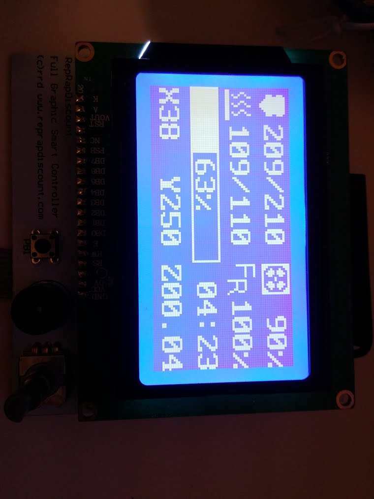
printer.cfg mod:
[lcd_st7920]
cs_pin: ar52
sclk_pin: ar50
sid_pin: ar51
small question but could rather have large answer: How does this affect max step rate on avr platforms? I will run tests anyways but its nice to hear an input to avoid missing out extra things when testing. Repetier firmware stutters on high facets gcode when using rotary encoder for example. I would worry if the encoder uses and affects interrupts significantly.
ghost
on 8 Feb 2018
@TunaLatte - Great! Was this with my merged code on branch work-lcd-20180115?
small question but could rather have large answer: How does this affect max step rate on avr platforms? I will run tests anyways but its nice to hear an input to avoid missing out extra things when testing. Repetier firmware stutters on high facets gcode when using rotary encoder for example. I would worry if the encoder uses and affects interrupts significantly.
I don't think it will significantly impact performance. The lcd code doesn't disable interrupts at all, and the button detection code only has a very small amount of code that runs with interrupts disabled. It could slow command processing (queuing of moves), but it's not difficult to prioritize regular commands over lcd commands so that doesn't seem like an issue either. Only testing will tell though.
KevinOConnor
on 9 Feb 2018
@KevinOConnor yes this was fresh clone branch work-lcd-20180115 on a VM snapshot.
Good to know thanks for now I will mess with return eventtime + 0.1 while printing smooth facets just to imagine what kind of misbehavior would happen.
Edit (0.02) for science :D :
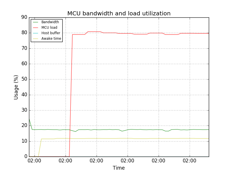
Heh I get a happy face icon at 0.01:
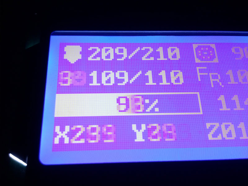
EDIT: FYI this is on Reprapdiscount GLCD without any hardware modification.
ghost
on 9 Feb 2018
@KevinOConnor I can confirm the lcd_hd44780 code also works on my RAMPS/reprapdiscount display combo.
cmock
on 11 Feb 2018
Good to know thanks for now I will mess with return eventtime + 0.1 while printing smooth facets just to imagine what kind of misbehavior would happen.
Interesting - can you grab the latest code and retry? Note the new config section as described in config/example-extras.cfg.
cd ~/klipper ; get fetch ; git checkout origin/work-lcd-20180115 ; sudo service klipper restart
This branch adds command prioritization for the lcd commands, it merges the hd44780 and st7920 code into a single module, and it uses "framebuffers" to reduce redundant screen updates. There's a good chance I totally messed up the st7920 code though.
KevinOConnor
on 12 Feb 2018
I'm really intrigued by your fast work on this. Kudos to everyone involved!
I haven't been able to gather from this thread, but would the LCD branch also add basic support to the RepRap Full Discount Displays running through a RAMPS 1.4 shield on an Mega 2560?
 jonathanlundstrom
on 12 Feb 2018
jonathanlundstrom
on 12 Feb 2018
Did I see a post somewhere that someone was combining this with the sd card version and adding a menu? Guess my real question is, is there an implementation uses this yet to get more then just demo functionality?
wizhippo
on 12 Feb 2018
@KevinOConnor : Sorry I've been out of the loop for a while, we're kind of in crunch mode trying to get a new product ready. It looks like things have been progressing here, however, and I am happy to see @TunaLatte's screenshot :)
marcio-ao
on 12 Feb 2018
@jonathanlundstrom : The RepRap Discount Full Graphic Smart Controller is what our LulzBot printers use, so if that is what you mean, then yes, it should work.
I'm not sure if anyone has done any work on a menu, but my original Arduino code shows how it could be accomplished. There is no way to highlight individual lines on the 128x64 using native commands (the "reverse line" command won't work as expected), but it is possible to fake it by writing the highlight to the graphics buffer, while printing the menu text to the text buffer. Perhaps a "highlight-line" could be implemented in the FW, as otherwise changing the highlight involves sending a 1K buffer of rows of 0xFFs and 0x00s -- alternatively, if the FW implemented run-length encoding, that could also be used to implement an efficient text highlight command for a menu.
marcio-ao
on 12 Feb 2018
Is there anyway to reset the lcd st7920 after power cycling the mcu? I have reset the mcu and on a number occasions I would have to power cycle the lcd too as restarting klipper I get an error that the st7920 isn't ready.
wizhippo
on 13 Feb 2018
@wizhippo : If you are using a bare LCD, there is a RST pin that can be brought low to reset the ST7920, but on the RepRap Discount Full Graphic Smart Controller this pin is tied high so there is no way to reset it from software. Marlin has some code to periodically clear the GDRAM, which may be the closest we could do to actually resetting the chip. What are the symptoms you are trying to solve? Are you seeing snow or corruption on the display? In Klipper, maybe the trick would be to fully-repaint the display (i.e. blast out the full contents of GDRAM and DDRAM) every few seconds to clear out any glitches that may arise.
marcio-ao
on 13 Feb 2018
@wizhippo : Actually, on rereading you comments, the error you are getting is something else. The ST7920 has no way to indicate readiness and in fact the communication is unidirectional so the LCD cannot report any status at all. I think the error message you are seeing about the LCD not being ready is something Klipper is generating during initialization, not something that the hardware is generating.
marcio-ao
on 13 Feb 2018
To reproduce:
Press reset button on mcu. Restart in octo print. Check status.
I get:
MCU 'mcu' error during config: st7920 not configured
wizhippo
on 13 Feb 2018
On Tue, Feb 13, 2018 at 05:49:55PM +0000, Douglas Hammond wrote:
To reproduce:
Press reset button on mcu. Restart in octo print. Check status.
I get:
MCU 'mcu' error during config: st7920 not configured
That sounds like a bug, but I'd need the fully klippy.log file to
diagnose it.
-Kevin
KevinOConnor
on 13 Feb 2018
@KevinOConnor as requested
klippy.log
wizhippo
on 13 Feb 2018
On Tue, Feb 13, 2018 at 05:49:55PM +0000, Douglas Hammond wrote:
To reproduce:
Press reset button on mcu. Restart in octo print. Check status.
I get:
MCU 'mcu' error during config: st7920 not configured
Conceptually Klipper treats the micro-controller code and host code as
a single "firmware". It's not expecting one to externally reset "half
the firmware". What happened here is that the micro-controller code
came back up after its reset and saw the pending requests to update
the lcd. But it didn't have the configuration for the lcd (because it
was reset). So, it correctly transitioned into an error state.
To clear the error state, don't use the RESTART command - instead use
the FIRMWARE_RESTART command (which clears errors from both the host
and the micro-controller).
-Kevin
KevinOConnor
on 13 Feb 2018
Hi,
I need help because I connected the reprap discount full graphic controller with the adaptor for the ramps, after I did "cd ~/klipper ; get fetch ; git checkout origin/work-lcd-20180115 ", after I did a make and flashed the arduino, changed the config file with this:
Reprap "128x64" graphics display
[lcd]
lcd_type: st7920
cs_pin: ar52
sclk_pin: ar50
sid_pin: ar51
and finally switched off and on all the things to be sure but nothing is displayed :-(
In octoprint terminal I can read :
"Recv: ok FIRMWARE_VERSION:v0.5.0-170-g5e8824d FIRMWARE_NAME:Klipper"
Can someone help me?
Thank you.
 andrea7376
on 14 Feb 2018
andrea7376
on 14 Feb 2018
On Wed, Feb 14, 2018 at 10:19:12PM +0000, andrea7376 wrote:
Hi,
I need help because I connected the reprap discount full graphic controller with the adaptor for the ramps, after I did "cd ~/klipper ; get fetch ; git checkout origin/work-lcd-20180115 ", after I did a make and flashed the arduino, changed the config file with this:Reprap "128x64" graphics display
[lcd]
lcd_type: st7920
cs_pin: ar52
sclk_pin: ar50
sid_pin: ar51and finally switched off and on all the things to be sure but nothing is displayed :-(
Can someone help me?
In the future, if you encouter difficulties, please attach your
klipper log file as described at:
https://github.com/KevinOConnor/klipper/blob/master/docs/Contact.md
Your pins are likely not correct - It's probably:
cs_pin: ar16
sclk_pin: ar23
sid_pin: ar17
Note that the lcd doesn't show anything useful at the moment - it's
just demo code.
-Kevin
KevinOConnor
on 15 Feb 2018
Sorry I forgot it, and thak you for your support.
Andrea
2018-02-15 8:03 GMT+01:00 KevinOConnor notifications@github.com:
On Wed, Feb 14, 2018 at 10:19:12PM +0000, andrea7376 wrote:
Hi,
I need help because I connected the reprap discount full graphic
controller with the adaptor for the ramps, after I did "cd ~/klipper ; get
fetch ; git checkout origin/work-lcd-20180115 ", after I did a make and
flashed the arduino, changed the config file with this:Reprap "128x64" graphics display
[lcd]
lcd_type: st7920
cs_pin: ar52
sclk_pin: ar50
sid_pin: ar51and finally switched off and on all the things to be sure but nothing is
displayed :-(
Can someone help me?In the future, if you encouter difficulties, please attach your
klipper log file as described at:
https://github.com/KevinOConnor/klipper/blob/master/docs/Contact.mdYour pins are likely not correct - It's probably:
cs_pin: ar16
sclk_pin: ar23
sid_pin: ar17Note that the lcd doesn't show anything useful at the moment - it's
just demo code.-Kevin
—
You are receiving this because you commented.
Reply to this email directly, view it on GitHub
https://github.com/KevinOConnor/klipper/issues/2#issuecomment-365841811,
or mute the thread
https://github.com/notifications/unsubscribe-auth/Afrdcol-g9lo1gQ6itxWrElukZ7yVdQzks5tU9axgaJpZM4M-xCQ
.
andrea7376
on 15 Feb 2018
Ok I got it working:
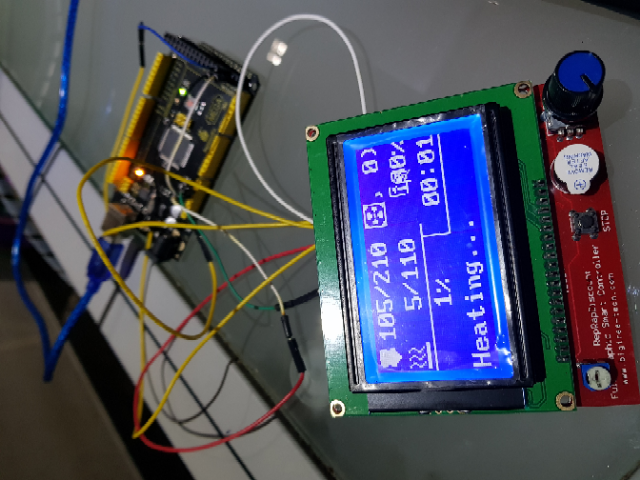
and the config for arduino mega:
[lcd]
lcd_type: st7920
cs_pin: ar50
sclk_pin: ar52
sid_pin: ar51
"cs_pin" is inverted respect the" sclk_pin" in the example config file...
Regards
Andrea
andrea7376
on 16 Feb 2018
On Fri, Feb 16, 2018 at 10:13:54PM +0000, andrea7376 wrote:
Ok I got it working:
Okay, thanks. Looks like I messed up the feedrate icon location. Is
the progress bar still messed up with the latest code?
cd ~/klipper ; git fetch ; git checkout origin/work-lcd-20180115 ; sudo service klipper restart
If so, where on the screen is the progress bar filled in?
-Kevin
KevinOConnor
on 17 Feb 2018
The progress bar have some problem.
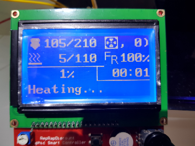
andrea7376
on 17 Feb 2018
On Sat, Feb 17, 2018 at 07:19:48AM +0000, andrea7376 wrote:
The progress bar have some problem.
Okay. I think it should be fixed now.
-Kevin
KevinOConnor
on 18 Feb 2018
@KevinOConnor
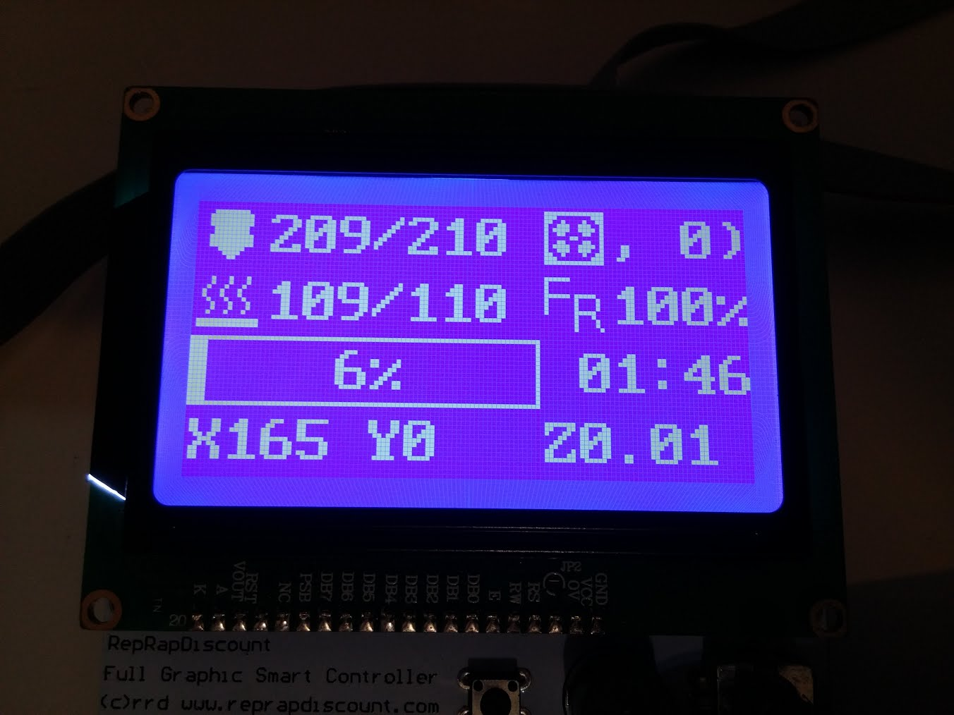
ghost
on 18 Feb 2018
Okay - thanks. I fixed the fan display. I also removed the demo code and hooked it up to display some actual printer status.
cd ~/klipper ; git fetch ; git checkout origin/work-lcd-20180115 ; sudo service klipper restart
-Kevin
KevinOConnor
on 18 Feb 2018
@KevinOConnor
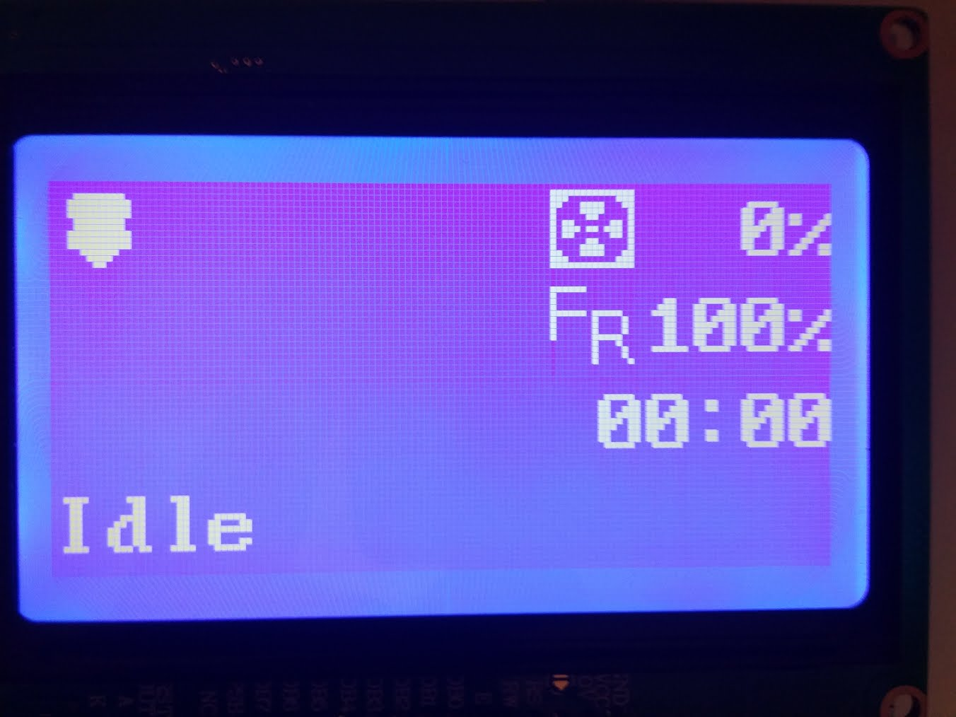
ghost
on 18 Feb 2018
I'm glad its done this way rather than sharing and using the regular SPI pins, as these are used for my tmc2130 drivers now, its difficult to modify a ramps to work concurrently due to limited space.
ghost
on 18 Feb 2018
@TunaLatte that picture looks a bit odd - do you not have an extruder, nor heater_bed, nor virtual_sdcard defined in your config?
KevinOConnor
on 18 Feb 2018
Apologies, misspressed vim recovery file menu, yes they were disabled*
virtual_sd wasn't enabled, just did:
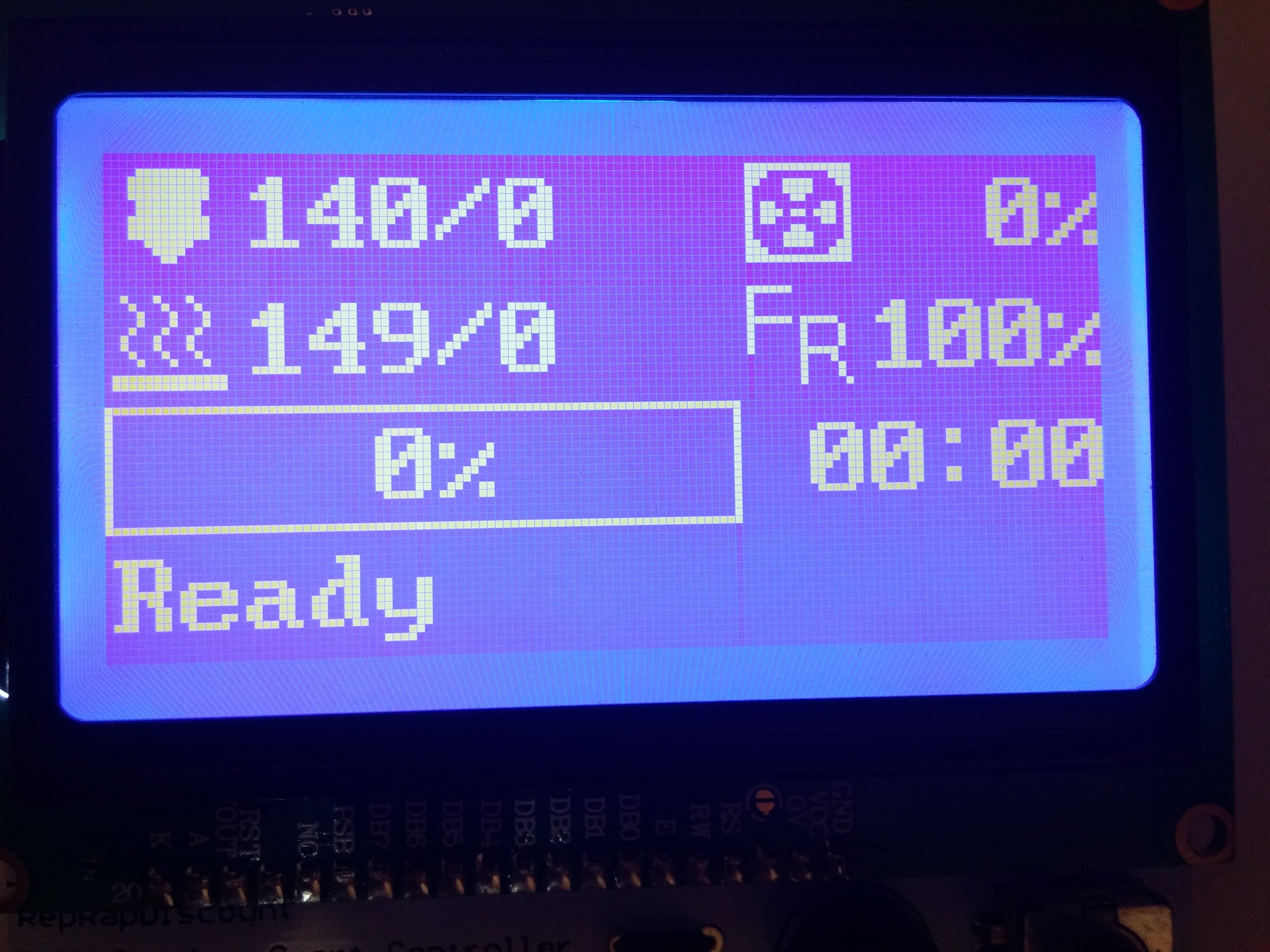
Nothing is connected to analog (no sensors) so its floating.
Edit: I'll try merging the code (and update mcu from this branch) with cruwaller's branch to test it on my main printer.
ghost
on 18 Feb 2018
Why mine is different?
I fetch last commit, the only difference is the pin mapping.
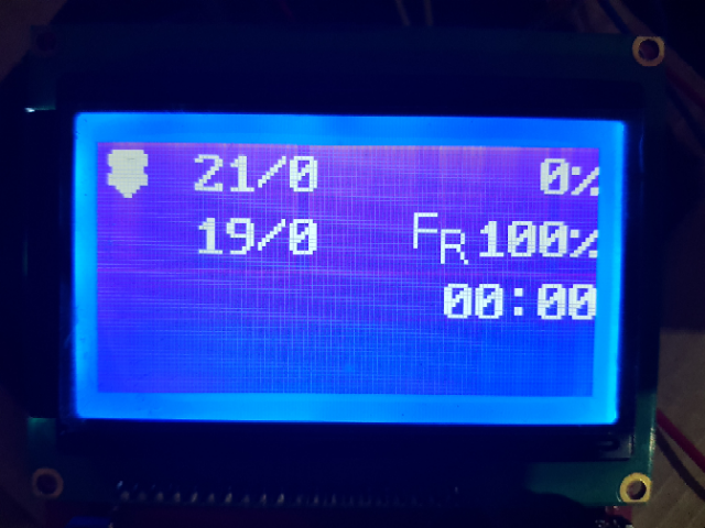
andrea7376
on 18 Feb 2018
On Sun, Feb 18, 2018 at 01:54:38PM -0800, andrea7376 wrote:
Why mine is different?
I fetch last commit, the only difference is the pin mapping.
I made additional changes that had an error in the glyph setup. Is it
still broken on the latest code? Note that you wont see the progress
bar unless you define a virtual_sdcard section in the config.
-Kevin
KevinOConnor
on 19 Feb 2018
@KevinOConnor : I finally had a chance to revisit this code. Using the latest code, I am getting a garbled display, but some elements are visible, so I believe it is just timing issues. I'll look at the code a bit and see if I can figure out what is going on.
marcio-ao
on 20 Feb 2018
On Tue, Feb 20, 2018 at 03:18:57PM +0000, Marcio Teixeira wrote:
@KevinOConnor : I finally had a chance to revisit this code. Using the latest code, I am getting a garbled display, but some elements are visible, so I believe it is just timing issues. I'll look at the code a bit and see if I can figure out what is going on.
Thanks. I made some recent changes that probably broke something.
I'm pretty sure that commit 1c4955a works. But, if not that then
e21a1bd was tested by @TunaLatte.
-Kevin
KevinOConnor
on 20 Feb 2018
@KevinOConnor : My guess is that there are manufacturing variances among the different displays and we are cutting it close. The following two delays solve it for me:
#define DELAY_62ns    __asm__("nop\n\t");

// Write eight bits to the st7920 via the serial interface.  The code
// is arranged to encourage avr-gcc to layout the code such that each
// sclk toggle is at least 200ns (4 clock cycles).
static __always_inline void
st7920_xmit_byte(struct gpio_out sclk, struct gpio_out sid, uint8_t data)
{
    uint8_t bits = 8;
    for (;;) {
        if (data & 0x80) {
            data = ~data;
            gpio_out_toggle(sid);
        }
        DELAY_62ns
        gpio_out_toggle(sclk);
        data <<= 1;
        if (!--bits)
            break;
        DELAY_62ns
        gpio_out_toggle(sclk);
    }
    gpio_out_toggle(sclk);
}
The most important delay seems to be the first one, but the second one clears up occasional glitches.
marcio-ao
on 20 Feb 2018
Hi,
I tested your last commit and they works, I didn't post a photo but I did a print and they show correctly the coordinate and all other things.
Can I suggest to write permanently the actual coordinate? They are very useful.
andrea7376
on 20 Feb 2018
It should be noted that this display is very common to have issues with wiring noise. I had glitches with dupoint cables, works ok with IDE cables, both work ok on short distances.
ghost
on 20 Feb 2018
@TunaLatte : Yes, the Marlin developers have chimed in that the ST7920 is one of the worst controllers out there. I would recommend adding those two delays as a safety margin, as this will probably help make it work for more users. Cable length and/or poor quality probably adds capacitance to the lines which increases the switching time. Boards which use lower voltages will also need longer delays, as capacitance and noise will be more of an issue. Marlin actually makes the various delays compile-time configurations since apparently there is so much variance.
@andrea7376 : The display code I contributed to Klipper was an early revision, the later version I pushed into Marlin added a timer that made it so the position would show up in place of the status message after a timeout.
That said, it looks like Kevin might have removed the progress bar, so there may be more room to put in the coordinates without having to hide the status.
marcio-ao
on 20 Feb 2018
On Tue, Feb 20, 2018 at 08:03:50AM -0800, Marcio Teixeira wrote:
@TunaLatte : Yes, the Marlin developers have chimed in that the ST7920 is one of the worst controllers out there. I would recommend adding those two delays as a safety margin, as this will probably help make it work for more users. Cable length and/or poor quality probably adds capacitance to the lines which increases the switching time. Boards which use lower voltages will also need longer delays, as capacitance and noise will be more of an issue. Marlin actually makes the various delays compile-time configurations since apparently there is so much variance.
Okay, adding a larger delay makes sense. With the delay, it works
with the latest (commit c76eecb9)?
If it does, could you try a quick test on branch work-lcd-20180219 - a
brief experiment in changing how the command delay timing is done.
The equivalent does not work on the HD44780, but maybe it will work on
the ST7920..
@andrea7376 : The display code I contributed to Klipper was an early revision, the later version I pushed into Marlin added a timer that made it so the position would show up in place of the status message after a timeout.
That said, it looks like Kevin might have removed the progress bar, so there may be more room to put in the coordinates without having to hide the status.
The progress bar only shows up if a virtual_sdcard section is present
in the config (without a virtual sdcard, there is no SD card printing
and no way to know how much progress there is).
-Kevin
KevinOConnor
on 20 Feb 2018
@KevinOConnor : I'm not sure I understand what a virtual SD card is -- is it documented anywhere? Anyhow, Marlin implements a M73 for setting the progress bar value from the host. Could Klipper make use of that as well?
marcio-ao
on 20 Feb 2018
On Tue, Feb 20, 2018 at 08:22:25AM -0800, Marcio Teixeira wrote:
@KevinOConnor : I'm not sure I understand what a virtual SD card is -- is it documented anywhere? Anyhow, Marlin implements a M73 for setting the progress bar value from the host. Could Klipper make use of that as well?
The virtual_sdcard adds the g-code sdcard commands - see
config/example-extras.cfg for the details. I'd add M73 if OctoPrint
generated it by default - otherwise it doesn't seem worth it.
-Kevin
KevinOConnor
on 20 Feb 2018
@KevinOConnor : The two delays work after commit c76eecb on work-lcd-20180219 and I double-checked that they are absolutely necessary for a clear display (without them I get a garbled display)
I'll give work-lcd-20180219 a try now.
marcio-ao
on 20 Feb 2018
@KevinOConnor : work-lcd-20180219 works fine for me.
marcio-ao
on 20 Feb 2018
@KevinOConnor : In fact, I suggest one simple optimization to work-lcd-20180219. I learned by examining the Marlin code that you can send multiple commands after a single sync, so this will work just as well and cuts down on having to send SYNC bytes.
static void
st7920_xmit_cmds(struct st7920 *s, uint8_t count, uint8_t *cmds)
{
    struct gpio_out sclk = s->sclk, sid = s->sid;
    st7920_xmit_byte(sclk, sid, SYNC_CMD);
    while (count--) {
        uint8_t cmd = *cmds++;
        st7920_xmit_byte(sclk, sid, cmd & 0xf0);
        _st7920_xmit_byte(sclk, sid, cmd << 4);
        // Last SCLK toggle must wait until 72us from last command
        while (timer_read_time() - s->last_cmd_time < CMD_WAIT_TICKS)
            ;
        gpio_out_toggle(sclk);
        s->last_cmd_time = timer_read_time();
    }
}
On Tue, Feb 20, 2018 at 08:47:40AM -0800, Marcio Teixeira wrote:
@KevinOConnor : In fact, I suggest one simple optimization to work-lcd-20180219. I learned by examining the Marlin code that you can send multiple commands after a single sync, so this will work just as well and cuts down on having to send SYNC bytes.
Makes sense. Thanks. I pushed everything back onto the
work-lcd-20180115 branch. It also has a slightly updated init
sequence for the st7920.
cd ~/klipper ; git fetch ; git checkout origin/work-lcd-20180115 ; sudo service klipper stop ; make flash ... ; sudo service klipper start
One other test that would be interesting is if we can write to the
graphics framebuffer without having to leave "extended mode". I'll
put together the test code for that.
-Kevin
KevinOConnor
on 20 Feb 2018
@KevinOConnor: I believe I tried that in my Marlin branch; leaving extended mode is necessary.
I am making a few improvements to "lcd.py" and will have a push request for you in a bit.
marcio-ao
on 20 Feb 2018
On Tue, Feb 20, 2018 at 05:35:52PM +0000, Marcio Teixeira wrote:
@KevinOConnor: I believe I tried that in my Marlin branch; leaving extended mode is necessary.
I am making a few improvements to "lcd.py" and will have a push request for you in a bit.
Okay, I wont bother with the test then. My latest code is commit
0598fbeb.
-Kevin
KevinOConnor
on 20 Feb 2018
I did some cleanup on the patches on the work-lcd-20180115 branch in preparation for merging into the master branch. If basic functionality looks okay on this code, I'll merge it into the master branch. We can then add improvements to the display as patches on top of that.
One change I did in this cleanup is to rename lcd.py to display.py so that the config name is now "[display]" instead of lcd. This will break patches on top of the previous code and require a change to the config files for those that have been testing. I wanted to do this before merging as I think "display" is a better config name.
cd ~/klipper ; git fetch ; git checkout origin/work-lcd-20180115 ; sudo service klipper stop ; make flash ... ; sudo service klipper start
KevinOConnor
on 21 Feb 2018
@KevinOConnor : Aside from the garbled row of characters at the end of the display, which I mentioned before, the new branch with cleanups work fine. I've reformatted two existing patches you hadn't yet incorporated and created two new pull requests on the cleaned up branch:
https://github.com/KevinOConnor/klipper/pull/186
https://github.com/KevinOConnor/klipper/pull/187
marcio-ao
on 21 Feb 2018
@KevinOConnor: I did some more investigation on the garbled end of lines and I learned two things. First, you were correct in that you were not violating the 0x0F wrap-around rule. I had initially written a check for writes over that boundary, but my check was incorrect and was generating false positives. Once I fixed that, I no longer see any warnings.
I have however managed to get rid of the garbled line endings by commenting out the following lines:
   def flush(self):
        # Find all differences in the framebuffers and send them to the chip
        for new_data, old_data, fb_id in self.framebuffers:
            if new_data == old_data:
                continue
            diffs = [[i, 1] for i, (nd, od) in enumerate(zip(new_data, old_data))
                     if nd != od]
            #for i in range(len(diffs)-2, -1, -1):
            #    if diffs[i][0] + 5 >= diffs[i+1][0] and diffs[i+1][1] < 16:
            #        diffs[i][1] = diffs[i+1][1] + diffs[i+1][0] - diffs[i][0]
            #        del diffs[i+1]
            for pos, count in diffs:
                count += pos & 0x01
                count += count & 0x01
                pos = pos & ~0x01
                chip_pos = pos >> 1
                if fb_id < 0x40:
                    # Graphics framebuffer update
                    self.send(self.send_cmds_cmd,
                              [0x26, 0x80 + fb_id, 0x80 + chip_pos, 0x22])
                    if int(pos / 32) != int((pos+count-1) / 32):
                        print("Write to graphics framebuffer spans line boundary. This will not work")
                else:
                    self.send(self.send_cmds_cmd, [fb_id + chip_pos])
                self.send(self.send_data_cmd, new_data[pos:pos+count])
            old_data[:] = new_data
It appears as if this code compacts differences into runs. There is something wrong here, because when I remove it, the display updates correctly, but at a much slower pace (because it is individually addressing each changed byte). BTW, perhaps I ought to clarify that at startup the graphics buffer contains all garbage. What is really happening here is that the Python code is failing to clear some of the bytes towards the end of the lines, and this is being caused by the run encoding code.
marcio-ao
on 21 Feb 2018
@KevinOConnor : This bit of code is really hard to understand, but it looks like you may be walking backwards through the list and combining adjacent difference records.
I presume the condition "diffs[i+1][1] < 16" means there is a limit of having each run be at most 16 bytes. Why is this check necessary, is there a buffer size limitation somewhere?
As for the condition "diffs[i][0] + 5 >= diffs[i+1][0]", I have no idea what it is for. Could you clarify?
marcio-ao
on 21 Feb 2018
On Wed, Feb 21, 2018 at 03:45:42PM +0000, Marcio Teixeira wrote:
@KevinOConnor: I did some more investigation on the garbled end of lines and I learned two things. First, you were correct in that you were not violating the 0x0F wrap-around rule. I had initially written a check for writes over that boundary, but my check was incorrect and was generating false positives. Once I fixed that, I no longer see any warnings.
I have however managed to get rid of the garbled line endings by commenting out the following lines:
[...]
It appears as if this code compacts differences into runs. There is something wrong here, because when I remove it, the display updates correctly, but at a much slower pace (because it is individually addressing each changed byte). BTW, perhaps I ought to clarify that at startup the graphics buffer contains all garbage. What is really happening here is that the Python code is failing to clear some of the bytes towards the end of the lines, and this is being caused by the run encoding code.
Thanks. That sounds like a timing issue then. Just to eliminate the
obvious timing issues, could you pull down again (and get commit
3e50f3d4), reflash and retest?
I'm wondering if 15 to 16 data bytes in a row is tickling some timing
issue. I don't think it's the encoding itself or the difference
tracking. Perhaps a delay is needed between writing a data byte and
writing the next command byte (which is covered in most cases because
lots of data bytes can go out in 72us).
-Kevin
KevinOConnor
on 21 Feb 2018
On Wed, Feb 21, 2018 at 04:05:28PM +0000, Marcio Teixeira wrote:
@KevinOConnor : This bit of code is really hard to understand, but it looks like you may be walking backwards through the list and combining adjacent difference records. I presume the condition "diffs[i+1][1] < 16" means there is a limit of having each run be at most 16 bytes. Why is this check necessary, is there a buffer size limitation somewhere? But as for the condition "diffs[i][0] + 5 >= diffs[i+1][0]", I have no idea what it is for. Could you clarify?
Yeah - it's hard for me to read too, and I wrote it.. I'll have to
redo it.
Here it is with less tuples and some comments:
Walk the list of positions that have changes in reverse order
for i in range(len(diffs)-2, -1, -1):
pos, count = diffs[i]
nextpos, nextcount = diffs[i+1]
# Check if this position is close to the next position and the next
# change isn't already very big.
if pos + 5 >= nextpos and nextcount < 16:
# Merge the next change into this change
diffs[i][1] = nextcount + (nextpos - pos)
# Delete the next change (which is now covered by this change)
del diffs[i+1]
The reason to limit to 16 (which doesn't actually limit to 16 as it
could go up to as high as 22 or so) is simply to avoid really huge
messages that may not interact well with the 64 byte block message
size.
-Kevin
KevinOConnor
on 21 Feb 2018
Thanks. That sounds like a timing issue then. Just to eliminate the
obvious timing issues, could you pull down again (and get commit
3e50f3d), reflash and retest?
@KevinOConnor : Success! It works!
The code you offered in an improvement, but one part which is confusing is the 0 and 1 indices on the tuples for position and size. How about using python named tuples to make it more clear?
            Diff = namedtuple('Diff', 'pos size')
            diffs = [Diff(i, 1) for i, (nd, od) in enumerate(zip(new_data, old_data))
                     if nd != od]
           # Walk the list of positions that have changes in reverse order
            for i in range(len(diffs)-2, -1, -1):
                # Check if this position is close to the next position and the next
                # change isn't already very big.
                if diffs[i].pos + 5 >= diffs[i+1].pos and diffs[i+1].size < 16:
                    # Merge the next change into this change
                    diffs[i] = Diff(diffs[i].pos, diffs[i+1].size + diffs[i+1].pos - diffs[i].pos)
                    # Delete the next change (which is now covered by this change)
                    del diffs[i+1]
@KevinOConnor : The display is rock solid now! I've restarted the printer several times and there are no glitches whatsoever! Thank you for all your work on this!
marcio-ao
on 21 Feb 2018
On Wed, Feb 21, 2018 at 04:29:04PM +0000, Marcio Teixeira wrote:
Thanks. That sounds like a timing issue then. Just to eliminate the
obvious timing issues, could you pull down again (and get commit
3e50f3d), reflash and retest?@KevinOConnor : Success! It works!
Interesting. Was it the nops or the change to st7920_xmit_cmds(). (I
think the "optimization" I had in st7920_xmit_cmds isn't worth it
anyway, but I'm curious if that was the cause or not.)
If the root cause was more nops, how many nops are needed?
The code you offered in an improvement, but one part which is confusing is the 0 and 1 indices on the tuples for position and size. How about using python named tuples to make it more clear?
I'll take a look. It's the inner loop of an inner loop, so I wrote it
to try and be compact, but that was probably not a good idea.
-Kevin
KevinOConnor
on 21 Feb 2018
@KevinOConnor : The changes to st7920_xmit_cmds don't matter. It seems to work fine like this:
// Delay between SCLK pulses while bit banging to the lcd chip
static void
st7920_bitbang_delay(void)
{
    if (CONFIG_MACH_AVR) {
        // On the AVR, a single NOP should be sufficient
        asm("nop\n");
        return;
    }
    uint32_t end = timer_read_time() + timer_from_us(1);
    while (!timer_is_before(end, timer_read_time()))
        irq_poll();
}
But not:
// Delay between SCLK pulses while bit banging to the lcd chip
static void
st7920_bitbang_delay(void)
{
    if (CONFIG_MACH_AVR) {
        // On the AVR, a single NOP should be sufficient
        asm("nop");
        return;
    }
    uint32_t end = timer_read_time() + timer_from_us(1);
    while (!timer_is_before(end, timer_read_time()))
        irq_poll();
}
I went back several times because I did not believe it was the "\n" making a difference, but it was.
marcio-ao
on 21 Feb 2018
On Wed, Feb 21, 2018 at 10:08:16AM -0800, Marcio Teixeira wrote:
I went back several times because I did not believe it was the "\n" making a difference, but it was.
Bleh.  If you put a newline there, then gcc thinks it is two assembler
instructions and then your version of gcc doesn't inline the
st7920_bitbang_delay() function.  Which then turns into a delay of 11
cycles instead of one cycle.  :-(
For testing, we can force st7920_bitbang_delay() to be inlined (I just
pushed that as commit b6a629ed).
-Kevin
KevinOConnor
on 21 Feb 2018
On Wed, Feb 21, 2018 at 04:34:36PM +0000, Marcio Teixeira wrote:
@KevinOConnor : The display is rock solid now! I've restarted the printer several times and there are no glitches whatsoever! Thank you for all your work on this!
FYI, I don't think the timing is right. Looking at the Marlin code,
it appears that the st7920 code is in ultralcd_st7920_u8glib_rrd.h.
(Though, as with much of Marlin, it's incredibly hard to figure out
what code is actually used.)
Some things I see there:
the delay between SCLK can very widely depending on config and
depending on whether or not the SCLK / SID pins can be accessed
atomically or not. It looks like almost all boards use a
ST7920_DELAY_x of 2 cycles. So, I'd guess a bit bang of a single
bit takes anywhere from 16 to 34 cycles depending on pin choice.there is a 10us delay after every byte written (data or command)
there isn't a delay between commands sent (but that may just be
because there are so many delays between data being sent)they do not go back to basic mode before writing frame buffer data.
(Indeed, it would seem they stay in extended mode forever.)
I'm wondering if the troubles you are seeing with the Klipper code
isn't the bit banging delay, but a delay needed between data write
commands. And, if the delay in the bitbanging code is helping because
it adds up to a delay big enough to meet the data write delay. That
is, are you seeing: 16 * bitbang_delay == datawrite_delay?
-Kevin
KevinOConnor
on 21 Feb 2018
Bleh. If you put a newline there, then gcc thinks it is two assembler
instructions and then your version of gcc doesn't inline the
st7920_bitbang_delay() function. Which then turns into a delay of 11
cycles instead of one cycle. :-(
You are correct. With the force inline, here are my results:
- One "nop" : garbled
- Two "nop" : works!
they do not go back to basic mode before writing frame buffer data.
(Indeed, it would seem they stay in extended mode forever.)
Ah, you just jogged my memory. I gave you incorrect information when I said it couldn't be done all in extended mode. I had thought that to be the case for the longest time, but looking at the Marlin code taught me otherwise, but I guess by the time you asked me, I had forgotten. Anyhow, I just tried some Arduino code that verifies that you can write to GDRAM entirely in extended mode.
- there is a 10us delay after every byte written (data or command)
Yes. I'm not sure why that is there -- it does not really seem to be necessary. I've found a couple mistakes in Marlin related to the ST7920, so I wouldn't assume all that is there is necessary.
- there isn't a delay between commands sent (but that may just be
because there are so many delays between data being sent)
Well, I just modified my Arduino test code to remove that delay and everything still works. The delay is stated as necessary in the datasheet, but right now I seem to be able to remove it. I'd be a little weary about removing that delay in production code, however. I feel like in the past I've had situations where it proved to be important. I wonder whether there are different versions of the ST7920?
marcio-ao
on 21 Feb 2018
@KevinOConnor: I just deleted the following lines in "lcd_st7920.c" and the display still works. So looks like the 72us is a datasheet myth:
        // Can't complete transfer until 72us from last command
        //while (timer_read_time() - s->last_cmd_time < CMD_WAIT_TICKS)
        //    irq_poll();
I guess I'll leave it up to you if you want to chance removing it in production code!
marcio-ao
on 21 Feb 2018
@KevinOConnor: Also just confirmed that the following change (to stay in extended function mode while updating the display), also works in conjunction with the removal of the 72us delay:
     def flush(self):
        # Find all differences in the framebuffers and send them to the chip
        for new_data, old_data, fb_id in self.framebuffers:
            if new_data == old_data:
                continue
            diffs = [[i, 1] for i, (nd, od) in enumerate(zip(new_data, old_data))
                     if nd != od]
            for i in range(len(diffs)-2, -1, -1):
                if diffs[i][0] + 5 >= diffs[i+1][0] and diffs[i+1][1] < 16:
                    diffs[i][1] = diffs[i+1][1] + diffs[i+1][0] - diffs[i][0]
                    del diffs[i+1]
            if fb_id < 0x40:
                # Enter extended mode
                self.send(self.send_cmds_cmd, [0x26])
            for pos, count in diffs:
                count += pos & 0x01
                count += count & 0x01
                pos = pos & ~0x01
                chip_pos = pos >> 1
                if fb_id < 0x40:
                    # Graphics framebuffer update
                    self.send(self.send_cmds_cmd,
                              [0x80 + fb_id, 0x80 + chip_pos])
                else:
                    self.send(self.send_cmds_cmd, [fb_id + chip_pos])
                self.send(self.send_data_cmd, new_data[pos:pos+count])
            if fb_id < 0x40:
                # Leave extended mode
                self.send(self.send_cmds_cmd, [0x22])
            old_data[:] = new_data
On Wed, Feb 21, 2018 at 09:11:46PM +0000, Marcio Teixeira wrote:
@KevinOConnor: I just deleted the following lines in "lcd_st7920.c" and the display still works. So looks like the 72us is a datasheet myth:
Interesting. I'm curious - could you pull the work-lcd-20180115
branch again, reflash, and see if it works? If it does work, could
you see how many nops you can remove from st7920_xmit_byte()?
I'm guessing it will work and you can remove all three nops.
-Kevin
KevinOConnor
on 22 Feb 2018
@KevinOConnor : You were correct. I was able to remove all the nops from "lcd_st7920.c"
I had expected that after all the tests we had done, that the one constant was that the nops in st7920_xmit_byte were necessary. But now, it seems they aren't. Apparently I don't understand this as well as I thought as I don't really understand what was changed from the time in which it was not working. I guess what counts is that it works now...
marcio-ao
on 22 Feb 2018
On Thu, Feb 22, 2018 at 06:23:08AM -0800, Marcio Teixeira wrote:
@KevinOConnor : You were correct. I was able to remove all the nops from "lcd_st7920.c"
I had expected that after all the tests we had done, that the one constant was that the nops in st7920_xmit_byte were necessary. But now, it seems they aren't. Apparently I don't understand this as well as I thought as I don't really understand what was changed from the time in which it was not working. I guess what counts is that it works now...
Thanks. The change is that I put the 72us delay back into the data
write path. We were working on the assumption that commands required
delays and data writes did not, but that appears to not be the case -
they both require a delay. This makes things more clear for me, and
it is very similar to the way my hd44780 display works.
My suspicion was that the reason you used to need the nops was because
there needed to be a larger data write command delay - 4 nops in the
bit transmit code is equivalent to a 4us command delay.
The code is quite a bit simpler when we only have to calibrate
commands delay. Could you run another test? The new code allows the
python code to specify the command delay. Assuming everything still
works, could you then try reducing the ST7920_DELAY parameter in
display.py. I suspect you need around a 25us delay. (Be sure to run
"sudo service klipper restart" on each change to the python code.)
-Kevin
KevinOConnor
on 22 Feb 2018
@KevinOConnor : I don't know what changed. But this no longer works at all. I get a mostly blank screen with a few rows of random pixels.
marcio-ao
on 22 Feb 2018
Even when I set ST7920_DELAY to .00072, I only get garbage.
marcio-ao
on 22 Feb 2018
On Thu, Feb 22, 2018 at 04:26:07PM +0000, Marcio Teixeira wrote:
Even when I set ST7920_DELAY to .00072, I only get garbage.
Okay, thanks. Does the latest code (commit 7c73117a) work?
The code tries to account for how long it takes to bit bang out a byte
- but it probably should always transmit at least two bytes.
-Kevin
KevinOConnor
on 22 Feb 2018
Nope. Just garbage.
marcio-ao
on 22 Feb 2018
On Thu, Feb 22, 2018 at 08:40:20AM -0800, Marcio Teixeira wrote:
Nope. Just garbage.
Hrmm. I guess I messed something up. Does commit a59e4489 work?
-Kevin
KevinOConnor
on 22 Feb 2018
Not at all. I feel like we're reached a point of diminishing return here and this is not very efficient use of our time. Why don't you revert to commit b6a629e, since we knew that was working. If you feel further optimizations are necessary, we can see whether my company is still willing to send you a display for testing.
marcio-ao
on 22 Feb 2018
On Thu, Feb 22, 2018 at 08:53:53AM -0800, Marcio Teixeira wrote:
Not at all. I feel like we're reached a point of diminishing return here and this is not very efficient use of our time. Why don't you revert to commit b6a629e, since we knew that was working. If you feel further optimizations are necessary, we can see whether my company is still willing to send you a display for testing.
Understood. Just to confirm, earlier today you ran commit f0dbc897
without the three nops and it did work, right?
Thanks,
-Kevin
KevinOConnor
on 22 Feb 2018
Well, geez. It's no longer working with that code either. I feel we just stepped into the Twilight Zone. Let me load up Marlin and see if I can revive the display.
marcio-ao
on 22 Feb 2018
If I load up Marlin, the display restores itself. But f0dbc89 is still not working with Klipper. I am trying to get back to commit b6a629e, but git doesn't recognize that as a hash. Did some history get erased?
marcio-ao
on 22 Feb 2018
On Thu, Feb 22, 2018 at 05:22:21PM +0000, Marcio Teixeira wrote:
If I load up Marlin, the display restores itself. But f0dbc89 is still not working with Klipper. I am trying to get back to commit b6a629e, but git doesn't recognize that as a hash. Did some history get erased?
The latest code is from a rebase, which would have removed the
intermediate commits I guess.
My local repo had that commit - I pushed it up as branch
work-lcd-20180220a.
-Kevin
KevinOConnor
on 22 Feb 2018
Well, at least I am back to getting something legible with work-lcd-20180220a rather than garbage. But it is something I've never seen before:
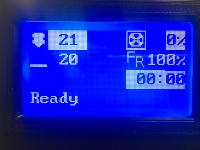
I think I now know why the Marlin developers have no love for the ST7920. It's a pretty unpredictable little beast.
marcio-ao
on 22 Feb 2018
And now after power cycling a couple times, the weird highlighting is gone.
marcio-ao
on 22 Feb 2018
It's fairly reproducible. Loading up 7c73117 puts the chip in a bad state that seems to survive a brief power cycle. From that point on, f0dbc89 fails too. Loading up work-lcd-20180220a is the only one that seems to fully initialize the chip to a known good state.
marcio-ao
on 22 Feb 2018
I got the weird highlighting issue again, once I had repeated the process of loading 7c73117 and trying to fix it with work-lcd-20180220a. Power cycling with work-lcd-20180220a loaded cleared up the remaining issue.
So for what it is worth, work-lcd-20180220a is the only one that can recover the chip to a legible state, even though it sometimes needs to run twice to do the job.
marcio-ao
on 22 Feb 2018
On Thu, Feb 22, 2018 at 06:13:26PM +0000, Marcio Teixeira wrote:
I got the weird highlighting issue again, once I had repeated the process of loading 7c73117 and trying to fix it with work-lcd-20180220a. Power cycling with work-lcd-20180220a loaded cleared up the remaining issue.
Well - that seems to indicate the st7920 has a usable reverse text
feature! Just need to figure out how to use it. :-)
So for what it is worth, work-lcd-20180220a is the only one that can recover the chip to a legible state, even though it sometimes needs to run twice to do the job.
Thanks. Lets take a break. At some point I'd like to know if
a59e4489 works okay. I also think the klipper code needs to set the
CS pin on each transmission (it currently just sets it high on startup
and leaves it that way). That's my guess why Marlin was able to reset
the display, but Klipper couldn't.
-Kevin
KevinOConnor
on 22 Feb 2018
At some point I'd like to know if a59e448 works okay.
It doesn't. Seems to behave like 7c73117.
Well - that seems to indicate the st7920 has a usable reverse text
feature! Just need to figure out how to use it. :-)
It has is a reverse line feature, but it's not very useful on a 128x64 display. The ST7920 behaves as if it is driving a 256x32 display, but this is "folded over" to cover 128x64 pixels. So highlighting line 1 causes lines 1 and 3 to be highlighted, while highlighting line 2 causes lines 2 and 4 to be highlighted. Not particularly useful. If there is a character highlight feature, as the glitch seems to indicate, it's definitely not documented anywhere!
marcio-ao
on 22 Feb 2018
On Thu, Feb 22, 2018 at 10:43:55AM -0800, Marcio Teixeira wrote:
At some point I'd like to know if a59e448 works okay.
It doesn't. Seems to behave like 7c73117.
Thanks. That was surprising, but I think I understand why. The minor
python changes inadvertently reordered the CS pin initialization wrt
the config_st7920 command, and I think that may have messed up the bit
sequencing.
FYI, I changed the code to do CS toggling on each transmission (commit
6387d628). I think the lcd_st7920.c code will have to be aware of CS
in order to ensure proper pin setup. I don't have much faith that the
timing is right in commit 6387d628 - it's my best guess as to what it
should be, but the chip timing is a bit of a mystery.
-Kevin
KevinOConnor
on 23 Feb 2018
That is embarrassing - it turns out that the reason my recent changes didn't work is that I messed up the bit-banging loop iterator. (It had "--bits" when it should have had "bits--".)
I've cleaned up the code on the work-lcd-20180115 branch and it has been confirmed on at least one st7920 and one hd44780. If there are no further problems, I'll look to commit basic display support into the master branch.
cd ~/klipper ; git fetch ; git checkout origin/work-lcd-20180115 ; sudo service klipper stop ; make flash ... ; sudo service klipper start
KevinOConnor
on 6 Mar 2018
@KevinOConnor : Works for me!
BTW, I made some improvements in upstream Marlin that I could back-port into Klipper -- basically adding a degree sign to the screen. However, I'll let you merge this branch into master before submitting a pull request for that change.
marcio-ao
on 6 Mar 2018
On Tue, Mar 06, 2018 at 02:33:58PM +0000, Marcio Teixeira wrote:
@KevinOConnor : Works for me!
Great! I committed the basic support to the master branch.
I also tried out some code for a separate layout on the hd44780
display (which is on the work-lcd-20180115 branch). I agree there
needs to be a balance between sharing code between hd44780/st7920 and
code complexity. Let me know what you think.
BTW, I made some improvements in upstream Marlin that I could back-port into Klipper -- basically adding a degree sign to the screen. However, I'll let you merge this branch into master before submitting a pull request for that change.
That would be great! I also need to get your other commits in. Can
you add a "signed-off-by" for them?
-Kevin
KevinOConnor
on 6 Mar 2018
How do I add a signed-off-by to my existing commits? Can I simply send you an e-mail as I have done before?
marcio-ao
on 6 Mar 2018
@KevinOConnor Am I being dumb? I did a git pull, rebuilt everything, flashed my MCU, copied the [display] config section into my printer config file but on start-up I get this message at the end of klippy.log...
[display]
lcd_type = hd47780
rs_pin = ar16
e_pin = ar17
d4_pin = ar23
d5_pin = ar25
d6_pin = ar27
d7_pin = ar29

=======================
Config error
Traceback (most recent call last):
  File "/home/pi/klipper/klippy/klippy.py", line 235, in _connect
    self._read_config()
  File "/home/pi/klipper/klippy/klippy.py", line 211, in _read_config
    self._try_load_module(config, section)
  File "/home/pi/klipper/klippy/klippy.py", line 196, in _try_load_module
    self.objects[section] = init_func(config.getsection(section))
  File "/home/pi/klipper/klippy/extras/display.py", line 496, in load_config
    return PrinterLCD(config)
  File "/home/pi/klipper/klippy/extras/display.py", line 374, in __init__
    self.lcd_chip = config.getchoice('lcd_type', LCD_chips)(config)
  File "/home/pi/klipper/klippy/klippy.py", line 108, in getchoice
    option, self.section))
Error: Option 'lcd_type' in section 'display' is not a valid choice
On Tue, Mar 06, 2018 at 06:11:32PM +0000, Alan Lord wrote:
@KevinOConnor Am I being dumb? I did a git pull, rebuilt everything, flashed my MCU, copied the [display] config section into my printer config file but on start-up I get this message at the end of klippy.log...
[display]
lcd_type = hd47780
Oops. The config example had a typo - it was supposed to be hd44780.
I've updated the example configs.
-Kevin
KevinOConnor
on 6 Mar 2018
On Tue, Mar 06, 2018 at 05:59:02PM +0000, Marcio Teixeira wrote:
How do I add a signed-off-by to my existing commits? Can I simply send you an e-mail as I have done before?
I find using "git rebase -i" to be the easiest way to revise things.
That said, for the past patches you can just add it to the github
comment and I'll update the commit message.
Thanks,
-Kevin
KevinOConnor
on 6 Mar 2018
:-D
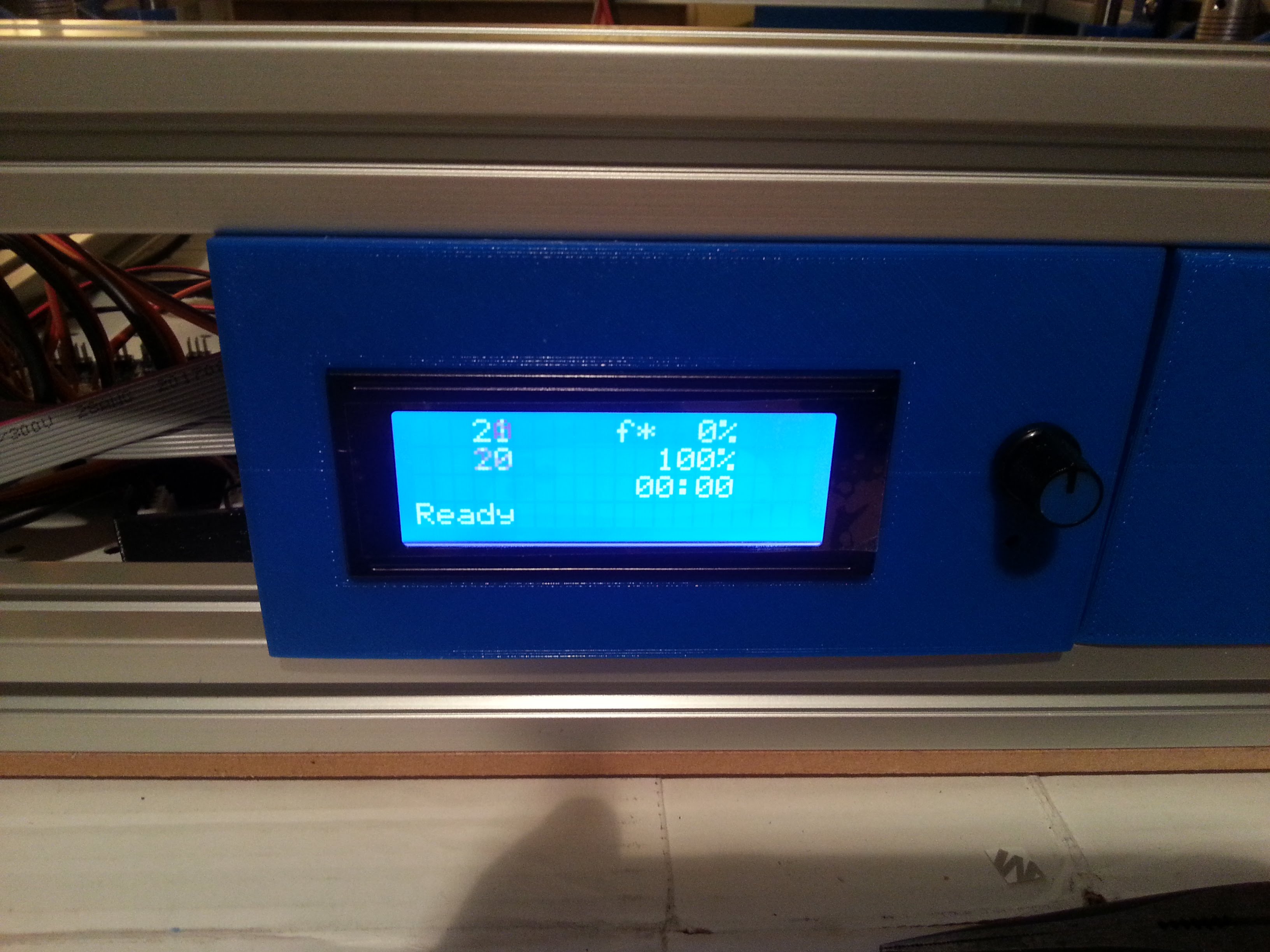
theopensourcerer
on 6 Mar 2018
What does that "f* 0%" actually mean?
theopensourcerer
on 6 Mar 2018
I think it's feedrate, but that's just a guess.
marcio-ao
on 6 Mar 2018
@theopensourcerer : Oh, I know. That is "fan" speed. The 100% below it is feedrate. @KevinOConnor code is basically identical to my graphical code, except that he substitutes in two characters in place of the icons.
marcio-ao
on 6 Mar 2018
I would think the strings ought to be "n1", "n2", "bt", "fs", "fr" for nozzle 1, nozzle 2, bed temp, fan speed and feedrate. "F*" is probably open to misinterpretation!
marcio-ao
on 6 Mar 2018
Thanks. Yes, I can confirm f* is for fan rate. I tried sending M106 Sxx and it shows the percentage.
theopensourcerer
on 6 Mar 2018

theopensourcerer
on 6 Mar 2018
One minor thing I noticed just now. When I used the Shutdown button in Octoprint to turn off my RPi, the display just froze. It would probably make more sense to either blank it or have some indication that the system is no longer active; if this is possible.
theopensourcerer
on 6 Mar 2018
I was thinking of just copying the picture you sent earlier @marcio-ao : https://user-images.githubusercontent.com/698003/36394228-df948318-1578-11e8-81f2-06d5c406bed1.png
The work-lcd-20180115 branch has the layout for that in place (but I didn't load the custom fonts yet). It's not a big deal to load them.
-Kevin
KevinOConnor
on 6 Mar 2018
FYI - I updated the work-lcd-20180115 with some custom fonts for the hd44780:
cd ~/klipper ; git fetch ; git checkout origin/work-lcd-20180115 ; sudo service klipper restart
KevinOConnor
on 6 Mar 2018
Someone please upload pics for those of us without a HD44780!
marcio-ao
on 6 Mar 2018
With the very latest code on work-lcd-20180115:
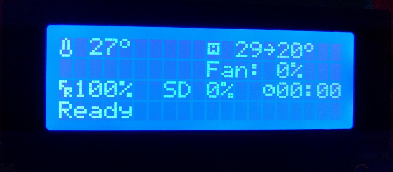
KevinOConnor
on 6 Mar 2018
FYI, ST7920 support works great in the changes that just got pushed to master. Here's the LCD output on latest code from master running on a Wanhao Duplicator i3 clone (Monoprice Maker Select v2.1).
Fan is set to 40%, extruder is heating to 240, bed to 75.
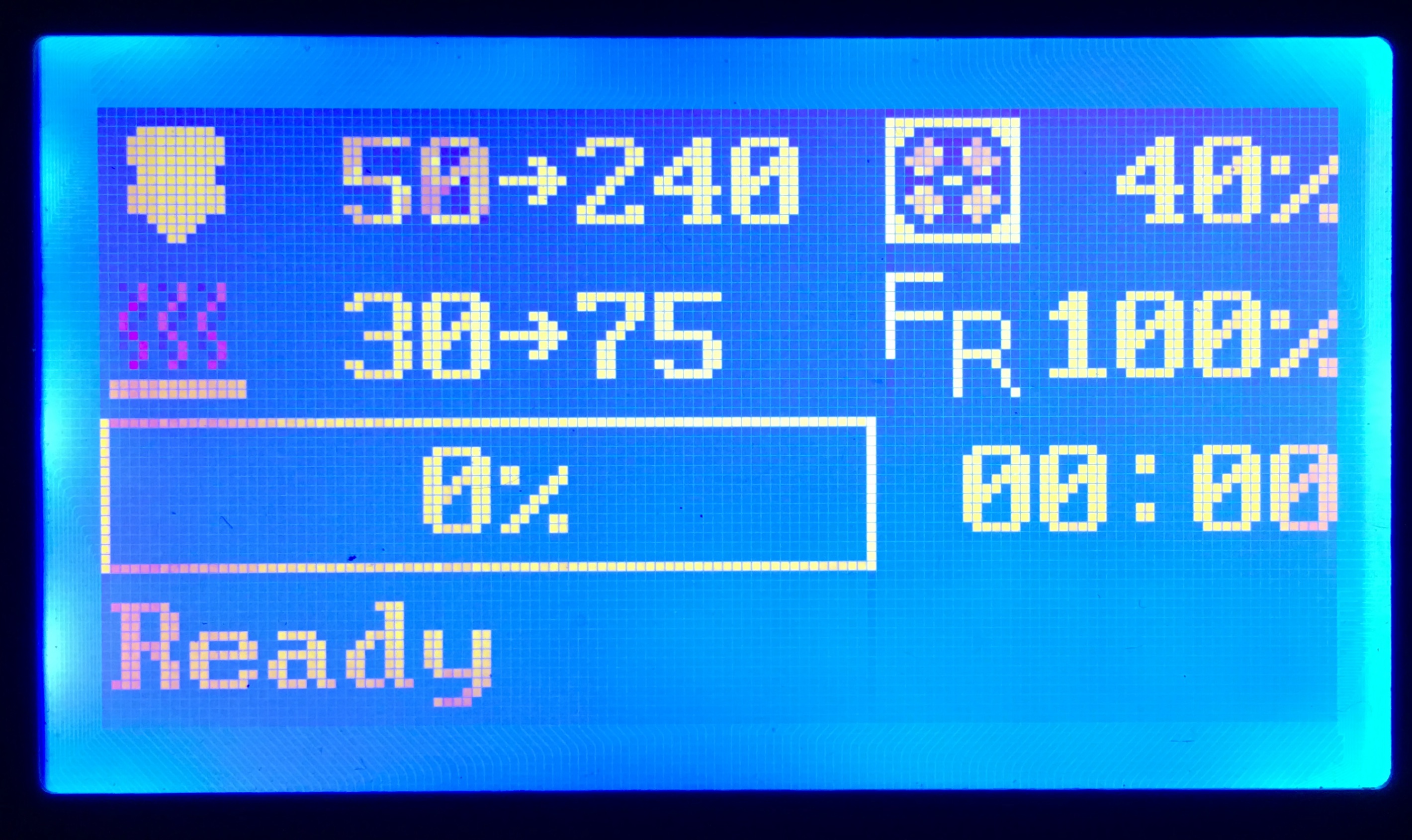
The printer basically runs a Melzi board talking to a ST7920-based clone of a ReprapDiscount Full Graphic Smart Controller (128 x 64), so anyone with a similar LCD should be in business now.
 ghandye
on 7 Mar 2018
ghandye
on 7 Mar 2018
How do I get the right pins for the CR-10 Display?
I checked the ATmega1284P Pinout and tried to get it runnning with the following settings:
[display]
lcd_type: st7920
cs_pin: (CS or RS) <= I have no real idea and tried some values, but nothing worked :(
sid_pin: PB5 (SID=R/W=MOSI ?!)
sclk_pin: PB7 (SCLK=E=SCK ?!)
How can I identify the right Pins? Is the st7920 the right LCD_type at all?
I'm stuck at the moment.
 burn2k
on 7 Mar 2018
burn2k
on 7 Mar 2018
@burn2k: According to Marlin developer thinkyhead, the following displays are ST7920 based:
- REPRAPWORLD_GRAPHICAL_LCD
- REPRAP_DISCOUNT_FULL_GRAPHIC_SMART_CONTROLLER
- LCD_FOR_MELZI
- SILVER_GATE_GLCD_CONTROLLER
- CR10_STOCKDISPLAY
So your CR10 should work, if you can find the correct pins.
One trick that I often use is using the Marlin code as a reference. If you know how to configure Marlin for the CR10, then you could see which ["pins_*.h"]
(https://github.com/MarlinFirmware/Marlin/tree/1.1.x/Marlin) file it is using for the CR10. Then, the trick is to convert Marlin pin numbers into Atmel pin names. It turns out you can do this by looking at the "fastio_1280.h" file. Look up the Marlin pin number in the line labeled "1280" (ignore the line labeled Marlin), and then the corresponding Atmel pin name is under "Port".
marcio-ao
on 7 Mar 2018
@burn2k: It looks like the CR10 uses the BOARD_MELZI_CREALITY, so, this corresponding pins file is this. There you can see the following:
#define LCD_SDSS           31 // Smart Controller SD card reader (rather than the Melzi)
#define LCD_PINS_RS        28 // st9720 CS
#define LCD_PINS_ENABLE    17 // st9720 DAT
#define LCD_PINS_D4        30 // st9720 CLK
#define FIL_RUNOUT_PIN     -1 // Uses Beeper/LED Pin Pulled to GND
So, the last step is to go to "fastio_1280.h" and convert those numbers to Atmel pin names:
- LCD_SDSS 31 -> PC6
- LCD_PINS_RS 28 -> PA6 // st9720 CS
- LCD_PINS_ENABLE 17 -> PH0 // st9720 DAT
- LCD_PINS_D4 30 -> PC7 // st9720 CLK
Assuming my trick works (it hasn't failed me yet), those should be the ports you need.
marcio-ao
on 7 Mar 2018
Ah, it looks like you need to use the "fastio_644.h" instead for the ATmega1284P (says right in the comments what chips it corresponds to). In that case:
- LCD_SDSS 31 -> PA0
- LCD_PINS_RS 28 -> PA3 // st9720 CS
- LCD_PINS_ENABLE 17 -> PC1 // st9720 DAT
- LCD_PINS_D4 30 -> PA1 // st9720 CLK
marcio-ao
on 7 Mar 2018
@marcio-ao Wow! Thank you, that did the trick.
Working config settings for the CR-10 stock display are:
[display]
lcd_type: st7920
cs_pin: PA3
sid_pin: PC1
sclk_pin: PA1
burn2k
on 7 Mar 2018
@burn2k : Let the source be with you!
marcio-ao
on 7 Mar 2018
On Wed, Mar 07, 2018 at 10:03:50AM -0800, burn2k wrote:
@marcio-ao Wow! Thank you, that did the trick.
Working config settings for the CR-10 stock display are:
[display]
lcd_type: st7920
cs_pin: PA3
sid_pin: PC1
sclk_pin: PA1
Great! I updated the cr-10 config (commit 385e6b67).
-Kevin
KevinOConnor
on 7 Mar 2018
Someone please upload pics for those of us without a HD44780!
Work fine work-lcd-20180115
[mcu]
serial: /dev/ttyACM0
pin_map: arduino
# "RepRapDiscount 2004 Smart Controller" type displays
[display]
lcd_type: hd44780
rs_pin: ar16
e_pin: ar17
d4_pin: ar23
d5_pin: ar25
d6_pin: ar27
d7_pin: ar29
Chinese ATMega2560 + Ramps.
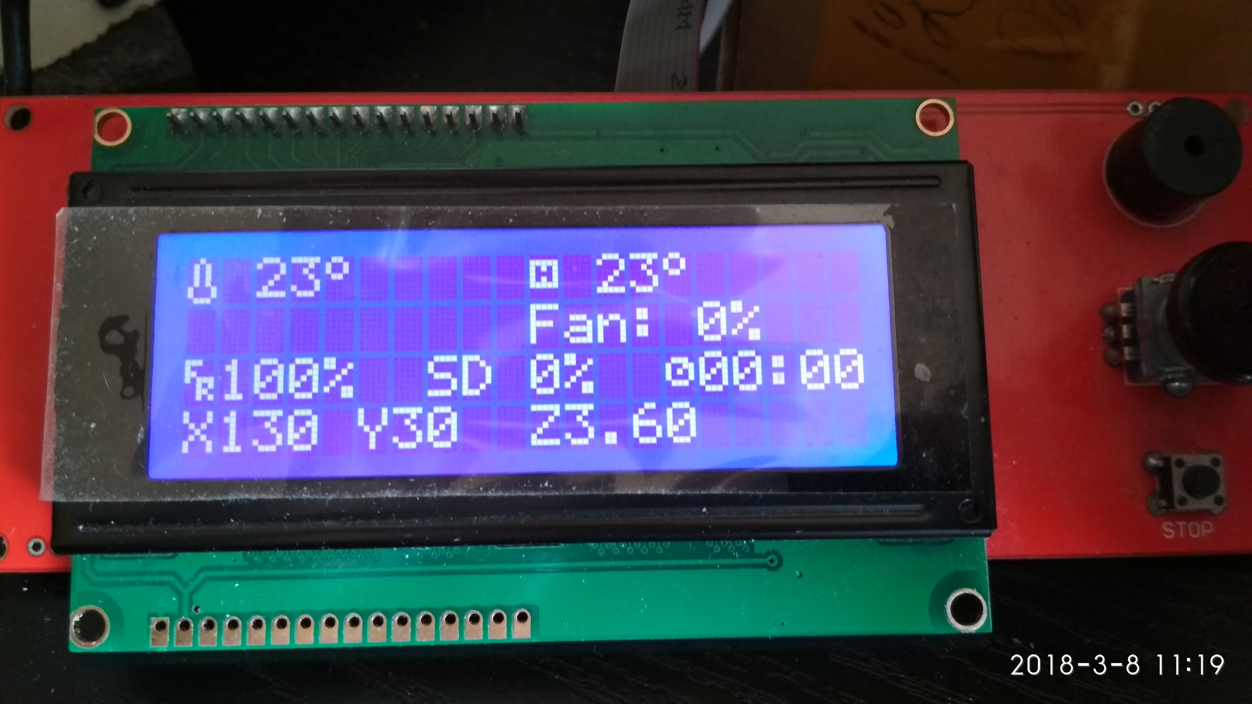
P.S.
Tip: To see the current coordinates without moving the head - press the "Fan on" / "Fan off" buttons in Octoprint.
 Alexdad76
on 8 Mar 2018
Alexdad76
on 8 Mar 2018
@KevinOConnor : I'd like to make a few enhancements to the LCD screen. Should I do it on the work-lcd-20180115 branch or wait until you merge into master?
marcio-ao
on 8 Mar 2018
On Thu, Mar 08, 2018 at 08:27:23PM +0000, Marcio Teixeira wrote:
@KevinOConnor : I'd like to make a few enhancements to the LCD screen. Should I do it on the work-lcd-20180115 branch?
That's probably a good idea.
I'm open to other ways of organizing the code, but that branch does
make the hd44780 display much nicer.
-Kevin
KevinOConnor
on 8 Mar 2018
It looks like my PRs, pr-lcd-enhancements, pr-lcd-status-scrolling, pr-lcd-status-scrolling were never merged in. I guess I don't want to make additional modifications if it's just going to cause conflicts with those.
marcio-ao
on 8 Mar 2018
@KevinOConnor : I am very confused as to what the state of the code and the various patches are right now. I would think it would make sense for you to either merge what you can back into master, or create a new LCD branch with what you think is the most up-to-date code. Once that is done, I can make a new PR on that branch with whatever was still left out. At this point, I feel like if I make any more PRs I will just be adding to the confusion.
marcio-ao
on 8 Mar 2018
On Thu, Mar 08, 2018 at 09:22:29PM +0000, Marcio Teixeira wrote:
It looks like my PRs, pr-lcd-enhancements, pr-lcd-status-scrolling, pr-lcd-status-scrolling were never merged in. I guess I don't want to make additional modifications if it's just going to cause conflicts with those.
Hi Marcio,
As far as I know, I've pulled everything besides the scrolling status
patch.
On Thu, Mar 08, 2018 at 01:44:43PM -0800, Marcio Teixeira wrote:
@KevinOConnor : I am very confused as to what the state of the code and the various patches are right now. I would think it would make sense for you to either merge what you can back into master, or create a new LCD branch with what you think is the most up-to-date code. Once that is done, I can make a new PR on that branch with whatever was still left out. At this point, I feel like if I make any more PRs I will just be adding to the confusion.
Okay, I cleaned up the hd44780 layout change and merged it to the
master branch. The only thing on the work-lcd-20180115 branch beyond
the master branch right now is the demo button reading code. (Should
someone want to take on adding menu support.)
I'll pull in the scrolling status patch if you wish. The reason I
haven't is that there is a big TODO in that patch and no code uses
scrolling yet. My general preference is to commit code when there is
a use case for it. That said, if this is in your way, I'll pull it
in.
Separately, I find git merges to be very confusing. So, I almost
always avoid them. When I pull in a change, I use "git rebase -i" and
"git cherry-pick". This makes the commit history more clear and that
helps quite a bit when tracking down regressions with "git bisect".
I'm guessing this is why github shows your PRs as not merged - it
didn't detect that I pulled them in via a rebase?
If you're strugging with the branches, my suggestion would be to avoid
git merges. Use "git fetch" to download new changes, and then do
something like "git rebase -i origin/work-lcd-20180115" to apply your
local commits on top of the upstream repo. That avoids the git merge
chaos.
Cheers,
-Kevin
KevinOConnor
on 9 Mar 2018
Thinking about this further, it's probably simplest to just base your work off of master going forward. The master branch will be stable, while the "work" branches that I use to test code are going to be under constant change.
-Kevin
KevinOConnor
on 9 Mar 2018
What will the code path look like for button pushes and encoder turns? I am thinking about what a user like myself will need to do to create a menu environment.
Thanks for all of this great work!
Gene
 w1ebr
on 9 Mar 2018
w1ebr
on 9 Mar 2018
@w1ebr: I've done some prototype Arduino code for a menu, so it certainly could be done in Klipper with a bit of work:
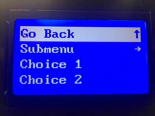
However, one question to consider is what will this menu be used for in Klipper? Since ordinarily the print is controlled by Octoprint, there is the question of what actions would a user want to initiate from the LCD panel that could not be initiated from Octoprint.
marcio-ao
on 9 Mar 2018
My use case: my printers are not directly next to a computer with a display, I have to get up and move a few steps, or to another room. That makes some things bothersome, and a few things are pretty impossible that way without a local user interface.
It has been suggested, I think in this issue, to use one of the octoprint apps on the smartphone. I do find that bothersome, because I have to put down and pick up the phone, unlock it etc.
Since it has also been suggested here to just drop a TFT touchscreen on the raspberry, I went that route, and of course I didn't like the two existing software solutions, so I wrote my own user interface.
What that does now, and what seems the bare minimum for my use case, is this (and all this can be done via octoprint and actually is implemented by calling the octoprint API):
start a print (from a file that's pre-selected in the octoprint web interface) -- so I can walk up to the printer, make sure the bed is clean etc, and then start and watch
stop and pause prints
set hotend and bed temperatures
home
move the head to the points for bed leveling
lift Z by 25mm for access to bed/print
load/unload filament (with a bowden setup, 500mm or more of movement is needed)
extrude/retract filament in steps of 5mm
shutdown, reboot octopi
instruct octoprint to connect to the printer
In the week I've been running this, I found it to be sufficient, I'm not missing all the other menu items of your typical printer firmware.
cmock
on 9 Mar 2018
I have a Melzi v2 displaying on a hd44780 now, with the following configuration:
[display]
lcd_type: hd44780
e_pin: PA2
rs_pin: PA3
d4_pin: PD2
d5_pin: PD3
d6_pin: PC0
d7_pin: PC1
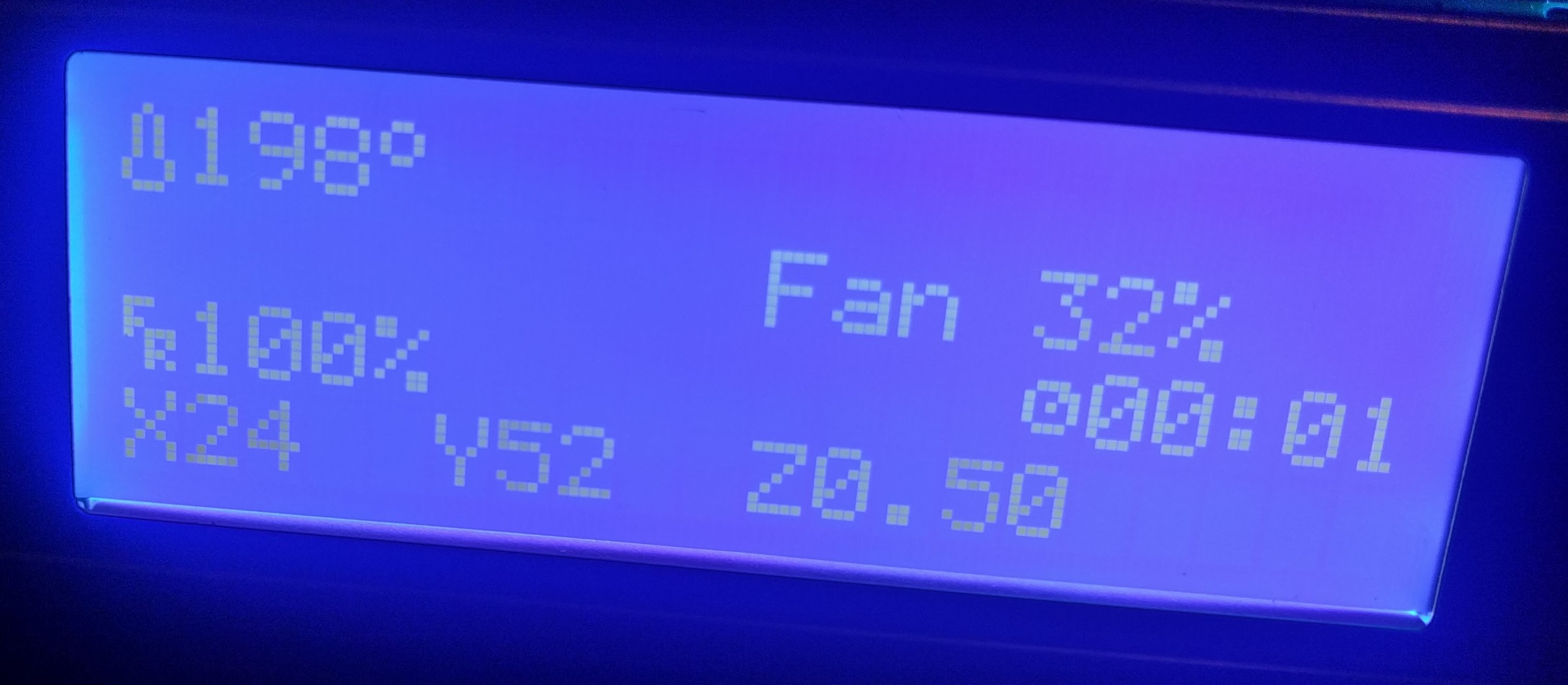
 davidjericho
on 10 Mar 2018
davidjericho
on 10 Mar 2018
The reason I asked about the code path for button and encoder detection is because there are several ways to implement anything. I am thinking about a low mcu priority extension to this work that would not compromise either the mcu base code performance or the klipper firmware performance (i.e. if you want to let people like me mess with an interface, let's protect them/us from messing up what's critical when what's needed doesn't require critical timing).
Could we have isolated code that is event driven on the input side and could make calls to the firmware interface (as Kevin already has for servos, for example) with commands that would allow one to compose an mcu attached display with either constant strings or formatted references to printer variables (i.e a frame buffer descriptor data structure). The input interface would still need to be event driven (perhaps invoking user code that could crash without messing up the core code.
This would limit the mcu code to low priority read/writes (maybe 50 msec resolution with debounce done with the mcu), require klipper firmware to call user code based on predefined conditions (like a button press) and accept firmware commands from a second source (unless you want everything routed through octoprint's input interface). This approach could handle most mcu attached misc. user hardware like buttons, filament sensors, etc.
Thoughts?
Gene
w1ebr
on 10 Mar 2018
On Sat, Mar 10, 2018 at 02:46:49PM +0000, w1ebr wrote:
The reason I asked about the code path for button and encoder detection is because there are several ways to implement anything. I am thinking about a non-performance critical extension to this work that would not compromise either the mcu base code performance or the klipper firmware performance (i.e. if you want to let people like me mess with an interface, let's protect them/us from messing up what's critical when what's needed doesn't require critical timing).
Could we have isolated code that is event driven on the input side and could make calls to the firmware interface (as Kevin already has for servos, for example) with commands that would allow one to compose an mcu attached display with either constant strings or formatted references to printer variables (i.e a frame buffer descriptor data structure). The input interface would still need to be event driven (perhaps invoking user code that could crash without messing up the core code.
This would limit the mcu code to non-performance critical read/writes (maybe 50 msec resolution with debounce done with the mcu), require klipper firmware to call user code based on predefined conditions (like a button press) and accept firmware commands from a second source (unless you want everything routed through octoprint's input interface). This approach could handle most mcu attached misc. user hardware.
Thoughts?
Well, I think most of that is basically done. Take a look at
klippy/extras/display.py:screen_update_st7920() - that python code
issues a handful of write_text() calls to update the screen. All the
low-level comms, prioritization, compression, and bit-banging are
handled automatically. I'm not sure if you are suggesting adding
g-code commands to do the above, but I don't think the extra half step
up to writing python code from writing esoteric g-code is
unreasonable.
Button presses aren't as well abstracted (see klippy/extras/buttons.py
on the work-lcd-20180115 branch for the demo code), but it's not that
far away either. Debouncing and comms are implemented in that demo
code.
-Kevin
KevinOConnor
on 11 Mar 2018
Wow! OK, I'll check this out!
I am not suggesting that adding esoteric G codes provides any added functionality. I am learning python and willing to go to work. However, I was suggesting that crashing klipper with my initially buggy python is a little less 'safe' than my initial badly formed g-code that would be rejected without crashing klipper.
BTW, allowing Z to go negative works beautifully. I see what gets displayed as the z offset as perspective. Marlin's display hid the real z coordinate during printing and only showed the g-code requested z coordinates. Klippy shows the actual z coordinates.
One last point. I am not going back to Marlin. I just finished printing out a toy dog in TPU (for my niece) and the difference in quality of the result is mind-blowing! I wish I had taken pictures of what Marlin did with the g-code so I could post them vs what klipper is doing! The Marlin results were drippy and retraction was a huge problem. The klipper results look like I printed the figure in PLA!!!
w1ebr
on 11 Mar 2018
No luck here getting reprap full graphic working. Ramps1.4/mega2560. Blank display.
[display]
lcd_type: st7920
cs_pin: ar49
sclk_pin: ar52
sid_pin: ar51
It's the standard type with rotary dial on bottom right, kill button and beeper.
 ml0w
on 19 Mar 2018
ml0w
on 19 Mar 2018
@ml0w:
From pins_RAMPS.h:
    #define LCD_PINS_RS         49 // CS chip select /SS chip slave select
    #define LCD_PINS_ENABLE     51 // SID (MOSI)
    #define LCD_PINS_D4         52 // SCK (CLK) clock
Then, use the pin mapping from fastio_1280.h, reading from the 1280 line to the Port line:
- 49 -> L0 // CS chip select /SS chip slave select
- 51 -> B2 // SID (MOSI)
- 52 -> B1 // SCK (CLK) clock
I bet this is what you want:
[display]
lcd_type: st7920
cs_pin: pl0
sclk_pin: pb1
sid_pin: pb2
@KevinOConnor : Humm, what does the notation "ar__" mean? It looks like @ml0w was using Marlin pin numbers in there? Is that supported?
marcio-ao
on 19 Mar 2018
On Mon, Mar 19, 2018 at 12:09:17AM -0700, mlow wrote:
No luck here getting reprap full graphic working. Ramps1.4/mega2560. Blank display.
[display]
lcd_type: st7920
cs_pin: ar49
sclk_pin: ar52
sid_pin: ar51It's the standard type with rotary dial on bottom right, kill button and beeper.
Can you attach the klippy.log file as described at:
https://github.com/KevinOConnor/klipper/blob/master/docs/Contact.md
It's the "full graphic 12864" style display (and not the 2004 style
display)?
-Kevin
KevinOConnor
on 19 Mar 2018
On Mon, Mar 19, 2018 at 04:15:07PM +0000, Marcio Teixeira wrote:
@KevinOConnor : Humm, what does the notation "ar__" mean? It looks like @ml0w was using Marlin pin numbers in there? Is that supported?
Klipper supports using the arduino pin numbers if the "pin_map:
arduino" setting is enabled (see config/example.cfg for the details).
This feature is intended for those using an arduino (like the ramps
boards do).
-Kevin
KevinOConnor
on 19 Mar 2018
@KevinOConnor : Ah. Thanks for the clarification. Looks like @ml0w had the correct pins then. Must be something else.
marcio-ao
on 19 Mar 2018
@KevinOConnor so do you want me to just turn off system, boot up and issue a m112 for that log file?
ml0w
on 20 Mar 2018
klippy_lcd.log
All I did was restart service, connect with octo, issue m112. Blank lcd with just backlight.
ml0w
on 20 Mar 2018
On Mon, Mar 19, 2018 at 12:09:17AM -0700, mlow wrote:
No luck here getting reprap full graphic working. Ramps1.4/mega2560. Blank display.
[display]
lcd_type: st7920
cs_pin: ar49
sclk_pin: ar52
sid_pin: ar51It's the standard type with rotary dial on bottom right, kill button and beeper.
Why did you use those three pins? My notes show ramps uses the
following pins (as found in config/generic-ramps.h):
"RepRapDiscount 128x64 Full Graphic Smart Controller" type displays
[display]
lcd_type: st7920
cs_pin: ar16
sclk_pin: ar23
sid_pin: ar17
-Kevin
KevinOConnor
on 21 Mar 2018
I really appreciate the amazing work done so far! However I don't understand the pin translation to get the display setup correctly on the CR-10s. Anyone know what the correct configuration is to get the graphics working?
 mikedahlgren
on 26 Mar 2018
mikedahlgren
on 26 Mar 2018
On Sun, Mar 25, 2018 at 11:12:00PM -0700, Mike Dahlgren wrote:
I really appreciate the amazing work done so far! However I don't understand the pin translation to get the display setup correctly on the CR-10s. Anyone know what the correct configuration is to get the graphics working?
The CR-10s uses a config similar to the RAMPS boards - so I'd try
using one of the lcd examples at the bottom of
config/generic-ramps.cfg .
-Kevin
KevinOConnor
on 26 Mar 2018
I can confirm what @KevinOConnor said to @mikedahlgren --
these settings worked (first try) on my CR-10s:
# "RepRapDiscount 128x64 Full Graphic Smart Controller" type displays
[display]
lcd_type: st7920
cs_pin: ar16
sclk_pin: ar23
sid_pin: ar17
 jm493
on 7 Apr 2018
jm493
on 7 Apr 2018
how can I connect MKS MINI 12864? Ramps1.4/mega2560
 #elif ENABLED(MINIPANEL)

  #define BEEPER_PIN 37
  // Pins for DOGM SPI LCD Support
  #define DOGLCD_A0  27
  #define DOGLCD_CS  25
  #define LCD_BACKLIGHT_PIN 65 // backlight LED on A11/D65
  #define SDSS   53
  #define KILL_PIN 64
  // The encoder and click button
  #define BTN_EN1 31
  #define BTN_EN2 33
  #define BTN_ENC 35
  // not connected to a pin
  #define SD_DETECT_PIN 49
Thank you
 danilovdorin
on 8 Apr 2018
danilovdorin
on 8 Apr 2018
On Sat, Apr 07, 2018 at 01:32:41AM +0000, John Mann wrote:
I can confirm what @KevinOConnor said to @mikedahlgren --
these settings worked (first try) on my CR-10s:# "RepRapDiscount 128x64 Full Graphic Smart Controller" type displays [display] lcd_type: st7920 cs_pin: ar16 sclk_pin: ar23 sid_pin: ar17
Thanks. I updated the default CR10s config file (commit 7c5f9ee4).
-Kevin
KevinOConnor
on 8 Apr 2018
@danilovdorin - if the board follows the RAMPS pin convention, then you'd also use the pins found in the config/generic-ramps.cfg file:
[display]
lcd_type: st7920
cs_pin: ar16
sclk_pin: ar23
sid_pin: ar17
KevinOConnor
on 8 Apr 2018
@danilovdorin - if the board follows the RAMPS pin convention, then you'd also use the pins found in the config/generic-ramps.cfg file:
[display]
lcd_type: st7920
cs_pin: ar16
sclk_pin: ar23
sid_pin: ar17
it's not work for me, because MKS MINI 12864 has some changes to the pin definitions.
http://reprap.org/mediawiki/images/f/ff/MKS_MINI12864_LCD_controller_pin_out_-_signal_names.jpg
I do not understand how to make an analogy between the pins that are in the marlin config file and ramps.
danilovdorin
on 9 Apr 2018
On Mon, Apr 09, 2018 at 09:56:46AM +0000, dn wrote:
@danilovdorin - if the board follows the RAMPS pin convention, then you'd also use the pins found in the config/generic-ramps.cfg file:
[display]
lcd_type: st7920
cs_pin: ar16
sclk_pin: ar23
sid_pin: ar17it's not work for me, because MKS MINI 12864 has some changes to the pin definitions.
If I understand it correctly, the "MKS MINI 12864" display is based on
the UC1701 lcd chip. Software would need to be written to support
that lcd chip in Klipper.
-Kevin
KevinOConnor
on 9 Apr 2018
We have basic UI support now. I'm going to close this issue. I understand more work could be done (in particular, menu support), but I don't think it makes sense to leave this issue open.
KevinOConnor
on 19 Apr 2018
Related issues
 ChiliApple
·
4Comments
ChiliApple
·
4Comments
 SergeyKrutyko
·
6Comments
SergeyKrutyko
·
6Comments
 Hywelmartin
·
6Comments
Hywelmartin
·
6Comments
 Michael-Bell
·
5Comments
Michael-Bell
·
5Comments
 sapell
·
3Comments
sapell
·
3Comments
Most helpful comment
@KevinOConnor : I think I have it working now. There was yet another undocumented behavior that was tripping me up (and which was tripping up your original test code). It turns out that you can write bytes to DRAM all you want, but the display will only refresh when you issue a non-write command (i.e. something with rs=0). Since my original demo all had an animation loop which intermixed RAM data writes and non-write commands, I was forcing refreshes all the time and I never noticed this issue.
Anyhow, now that I got the basics down, I'll try optimizing things a bit and adding a more interesting interface.