Irremoteesp8266: Voltas AC Remote IR Mapping
Hola @crankyoldgit et al.
I have put in a day's work to try and reverse engineer my AC's IR Remote mapping and after necessary following the steps given in the two wiki articles explaining how to do so, I've come up with the following results:
Voltas AC map (Model no: 122LZF 4011252 Window AC)
(MSBF)
byte 0
b0 = Horizontal Swing(1 = On, 0 = Off) (Works with all Basic Modes) (not compatible with my AC)
b7-1 = UNKNOWN, typically 0b1111100
(Becomes Don't Care with value 0b00110011(0x33) if any other parameter is changed, reason unknown)
byte 1
b3-0 = Basic Modes
1000 (8) = Chill
0100 (4) = Dry (fixed Fan speed(Low), fixed Temperature(24C))
0010 (2) = Cool
0001 (1) = Fan (Fixed fan speed(Hi), Temperature = Cool mode temperature)
b4 = UNKNOWN, typically 0
b7-5 = Fan speed
100 (1) = Low
010 (2) = Mid
001 (4) = Hi
111 (7) = Auto
byte 2
b2-0 = Vertical Swing (Works with all Basic Modes)
000 (1) = Off
111 (7) = On
b3 = WiFi bit(Toggles between 0 and 1 upon pressing the button labelled 'WiFi') (not compatible with my AC)
b4 = UNKNOWN, typically 0
b5 = Turbo mode(1 = On, 0 = Off) (Works only with Chill mode)
b6 = Sleep mode(1 = On, 0 = Off) (Works only with Chill mode)
b7 = Power Status(1 = On, 0 = Off)
byte 3
b3-0 = Temperature
0000 (0) = 16C
0001 (1) = 17C
0010 (2) = 18C
...
1101 (13) = 29C
1110 (14) = 30C
b5-4 = UNKNOWN, typically 0b01
b6 = Energy Saver mode (1 = On, 0 = Off) (Works only with Chill mode)
b7 = TEMP bit, goes HIGH for a few seconds upon pressing TEMP button, then changes back to LOW automatically and remote sends the message(not compatible with my AC)
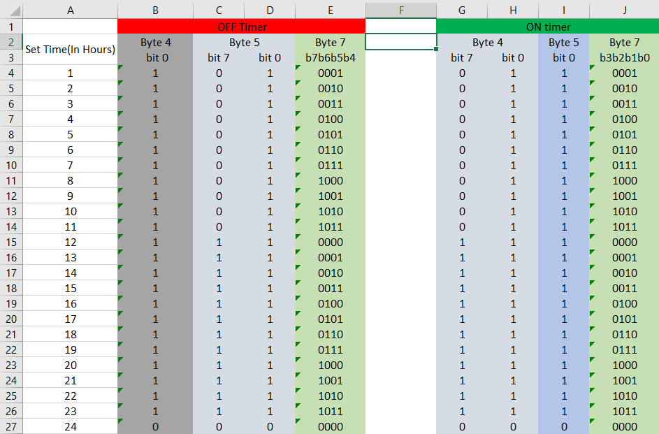
byte 4
b0 = Timer 24 Hr. bit (Works for both On and Off timer)
0 = Time is 24 Hr.
1 = Otherwise
b6-1 = UNKNOWN, typically 0b011101
b7 = On Timer 12+(byte 7 lower nibble) bit (works in conjuction with byte 7)
0 = On Time is 24 Hr or Time < 12 Hrs.
1 = On Time =>12 Hr.
byte 5
b0 = Timer 24 Hr. bit (Works for both On and Off timer)
0 = Time is 24 Hr.
1 = Otherwise
b6-1 = UNKNOWN, typically 0b011101
b7 = Off timer 12+(byte 7 upper nibble) bit (works in conjuction with byte 7)
0 = Off Time is 24 Hr or Off Time < 12 Hrs.
1 = Off Time =>12 Hr.
byte 6 = UNKNOWN, typically 0b00111011(0x3B)
byte 7
b3-0 = On Timer bits (works in conjuction with byte 4)
0000 (0) = 12 Hr. / 24Hr.
0001 (1) = 1 Hr. / 13Hr.
0010 (2) = 2 Hr. / 14Hr.
...
1010 (10) = 10 Hr. / 22Hr.
1011 (11) = 11 Hr. / 23Hr.
b7-4 = Off Timer bits (works in conjuction with byte 5)
0000 (0) = 12 Hr. / 24Hr.
0001 (1) = 1 Hr. / 13Hr.
0010 (2) = 2 Hr. / 14Hr.
...
1010 (10) = 10 Hr. / 22Hr.
1011 (11) = 11 Hr. / 23Hr.
byte 8
b4-0 = UNKNOWN, typically 0b00000
b5 = Lamp bit(1 = On, 0 = Off) (not compatible with my AC)
b6 = Off Timer status (1 = Activated, 0 = Deactivated)
b7 = On Timer status (1 = Activated, 0 = Deactivated)
(On Timer can only be activated when the AC has been powered OFF from the remote, Off Timer can only be activated when the AC has been powered ON from the remote,)
byte 9 = Check byte
Calcuted using the following formula:
checksum = ~(Sum of all preceding bytes)&0xFF
My setup is a NodeMCU connected to an IR receiver I salvaged from a digital photo frame.

A few of the IRrecvDumpV3 outputs after modifying the library are given below:
- Dry Mode, No Swing, No Lamp, No Timer
Library   : v2.7.9

Protocol  : VOLTAS
Code      : 0x338488183B3B3B1100E6 (80 Bits)
uint16_t rawData[161] = {1002, 584,  1000, 586,  1000, 2568,  1002, 2570,  1002, 586,  998, 588,  1000, 2568,  1002, 2570,  1002, 2572,  1002, 584,  1002, 586,  1000, 584,  1000, 586,  1002, 2568,  1004, 584,  1000, 586,  1002, 2568,  1002, 584,  1002, 584,  1004, 584,  1000, 2568,  1002, 586,  1000, 586,  998, 590,  998, 584,  1002, 584,  1000, 586,  1000, 2570,  1002, 2568,  1004, 584,  1000, 584,  1002, 584,  1002, 582,  1004, 584,  1002, 2568,  1002, 2570,  1004, 2570,  1000, 586,  1002, 2568,  1004, 2568,  1006, 584,  1000, 584,  1002, 2568,  1002, 2570,  1002, 2568,  1002, 586,  1002, 2570,  1000, 2570,  1002, 588,  998, 586,  1000, 2568,  1004, 2568,  1004, 2568,  1002, 588,  998, 2570,  1002, 2568,  1004, 586,  1002, 584,  1000, 586,  1000, 2570,  1000, 586,  1000, 584,  1002, 586,  1000, 2568,  1004, 584,  1000, 586,  1000, 586,  1002, 584,  1002, 586,  1000, 586,  1000, 586,  1000, 586,  1000, 2568,  1002, 2568,  1002, 2568,  1004, 586,  1000, 584,  1000, 2570,  1004, 2568,  1004, 584,  1002};  // VOLTAS
uint8_t state[10] = {0x33, 0x84, 0x88, 0x18, 0x3B, 0x3B, 0x3B, 0x11, 0x00, 0xE6};
- Chill mode(24C), no swing, Fan Auto, Turbo ON, No Timer, No lamp
Library   : v2.7.9

Protocol  : VOLTAS
Code      : 0x33E8A8183B3B3B110062 (80 Bits)
uint16_t rawData[161] = {1014, 574,  1012, 574,  1012, 2558,  1014, 2558,  1014, 574,  1014, 574,  1012, 2558,  1014, 2558,  1014, 2558,  1014, 2558,  1014, 2556,  1014, 574,  1012, 2558,  1014, 574,  1012, 574,  1012, 574,  1012, 2558,  1014, 572,  1014, 2558,  1014, 574,  1010, 2558,  1014, 574,  1012, 574,  1012, 574,  1012, 574,  1012, 572,  1014, 572,  1012, 2558,  1014, 2556,  1014, 572,  1036, 550,  1036, 550,  1012, 574,  1012, 576,  1010, 2556,  1038, 2534,  1038, 2534,  1016, 572,  1038, 2530,  1014, 2558,  1038, 548,  1012, 574,  1034, 2534,  1016, 2556,  1038, 2534,  1014, 574,  1012, 2558,  1014, 2558,  1014, 574,  1012, 572,  1012, 2558,  1014, 2556,  1014, 2558,  1014, 574,  1012, 2556,  1038, 2534,  1014, 572,  1012, 574,  1012, 574,  1036, 2534,  1012, 574,  1012, 574,  1012, 574,  1036, 2532,  1016, 572,  1014, 572,  1012, 574,  1012, 574,  1012, 572,  1014, 572,  1012, 574,  1012, 572,  1012, 574,  1012, 2556,  1014, 2556,  1014, 574,  1010, 574,  1012, 574,  1012, 2558,  1014, 572,  1014};  // VOLTAS
uint8_t state[10] = {0x33, 0xE8, 0xA8, 0x18, 0x3B, 0x3B, 0x3B, 0x11, 0x00, 0x62};
Also I've built an IR sender circuit and can confirm that the AC is responding to the change in parameters, with the correct checksum only.
Can you please confirm if I'm on the right path, so I can proceed towards the coding part, which admittedly, doesn't happen to be my strongest suit.
Voltas Remote pic:

 manj9501
All 111 comments
Can you please confirm if I'm on the right path, so I can proceed towards the coding part, which admittedly, doesn't happen to be my strongest suit.
Yes, it looks like you're on the correct path. Given you've got a steadily increasing value for the temp in Byte 3, I'd say you've got the bit ordering correct. So, congrats! You're well on the way to having this all figured out, or already have enough to make it completely usable.
Feel free to submit a PR with what you've got so far and we can work on getting it as supported as we can.
As I say in the wiki/faq etc, if you do the decoding/reverse engineering of the protocol, I'll typically do the coding for you.
It looks like you've worked out enough of the protocol (inc the all-important checksum) that we can add support for it fairly simply. However, if you want to do the coding, feel free, I won't stop you. ;-)
Things I'll ask in advance:
1) What is the model number of the remote (if any)?
2) Is there a heat mode on the remote? (if so, what code does it produce)
3) Re: Byte[0], does _"any other parameter is changed"_ apply to the entire IR message, or just Byte[0]?
4) In your notation/description, is b0 the LEAST significant bit, or the MOST?
5) Re: Byte[3] b7, does the unit still change the temp if a message has a different temp & b7 is 0? i.e. do we have to have this flagged if we change the temp? And how does the unit behave if it was always 1?
6) Re: Byte[4 & 5], b0, Can you elaborate on what you mean here? It isn't immediately obvious.
 crankyoldgit
on 14 Aug 2020
crankyoldgit
on 14 Aug 2020
- What is the model number of the remote (if any)?
I've probably misplaced the manual for this AC, so I can't really help you with the model number of the remote right now.
- Is there a heat mode on the remote? (if so, what code does it produce)
No, there is no such mode on the remote.
- Re: Byte[0], does "any other parameter is changed" apply to the entire IR message, or just Byte[0]?
It applies to the entire IR message. Peculiar behavior!
- In your notation/description, is b0 the LEAST significant bit, or the MOST?
b0 is the LSB.
- Re: Byte[3] b7, does the unit still change the temp if a message has a different temp & b7 is 0? i.e. do we have to have this flagged if we change the temp? And how does the unit behave if it was always 1?
If we press the TEMP button, Byte[3] b7 is SET but when we change the temperature on the remote, before letting Byte[3] b7 return to RESET, the remote sends Byte[3] with this flag RESET.
Also I did some research on this TEMP function. It has to do with temperature display on the AC unit showing the ambient temperature for 5 secs before coming back to showing the temperature set using the remote. But as I mentioned, my AC is a rather dumb one and it doesn't show ambient temperature.
So, I suppose it'll take some more research for me to properly answer this question.
- Re: Byte[4 & 5], b0, Can you elaborate on what you mean here? It isn't immediately obvious.
Following table may make it clear:

Also, there's something I wanna add w.r.t. the OFF Timer functionality. The time bits will always be according to the time that was there on the remote before the OFF Timer is deactivated.
Say, the OFF Timer was previously activated and was set to 13 hours. After a while, we deactivated the OFF Timer with the remote still showing 13 hours. Now the time signature that will be sent with each command will be of 13 hours, even though the OFF Timer bit is RESET.
manj9501
on 14 Aug 2020
Coming back to Byte[3] b7, I did some testing by modifying the IRsendDemo.
I hard coded this bit to SET and played around with the temperature bits.
What I noticed was that the temperature was definitely being updated on my AC unit, despite the bit being SET all the time.
manj9501
on 14 Aug 2020
I've probably misplaced the manual for this AC, so I can't really help you with the model number of the remote right now.
No worries. If there isn't one printed on the remote (sometimes in the battery compartment) then we will just do without. ;-)
crankyoldgit
on 15 Aug 2020
I've looked in the battery compartment too, though without any breakthroughs.
Once I lay my hands on the manual and the remote model no. does happen to be there, I'll definitely revert back.
Plus, I hope I was able to clear your previous doubts with regards to the state mapping.
manj9501
on 15 Aug 2020
I've looked in the battery compartment too, though without any breakthroughs.
Once I lay my hands on the manual and the remote model no. does happen to be there, I'll definitely revert back.
No rush & not urgent.
Plus, I hope I was able to clear your previous doubts with regards to the state mapping.
Yep. All good. I won't know more till I start coding. Speaking of which, can you please send what you've got working so far? Preferably in the form of a Pull Request (PR). Once I have it I'll start working on it.
crankyoldgit
on 16 Aug 2020
Now I've cleaned up & merged your PR, I'll start on the detailed support for the protocol.
crankyoldgit
on 16 Aug 2020
@manj9501 I'm adding detailed support in branch: https://github.com/crankyoldgit/IRremoteESP8266/tree/detailed_voltas
Feel free to follow along & download + test while I add to it. It's far from finished at the moment, so don't expect much.
crankyoldgit
on 16 Aug 2020
Feel free to follow along & download + test while I add to it.
Yes, doing it now!
manj9501
on 16 Aug 2020
No sooner did I upload the IRrecvDumpV3 example from _detailed_voltas_ branch on to my NodeMCU setup than I discovered the significance of the 'don't expect much' part of your statement.
I encountered a rapidly, repeatedly crashing NodeMCU with the following Serial Log:
ets Jan  8 2013,rst cause:2, boot mode:(3,6)

load 0x4010f000, len 3584, room 16
tail 0
chksum 0xb0
csum 0xb0
v2843a5ac
~ld

User exception (panic/abort/assert)
--------------- CUT HERE FOR EXCEPTION DECODER ---------------

Panic IRrecvDumpV3.ino:131 void setup(): Assertion 'irutils::lowLevelSanityCheck()' failed.

>>>stack>>>

ctx: cont
sp: 3fffff30 end: 3fffffc0 offset: 0000
3fffff30:  0000001c 0001c200 00000000 00000000
3fffff40:  000000fe 00000000 00000000 00000000
3fffff50:  00000000 00000000 00000000 4024fa30
3fffff60:  3ffeee94 00000000 3ffeed38 3ffeee54
3fffff70:  3fffdad0 00000000 3ffeed38 40216f36
3fffff80:  0001c200 0000001c 00000002 40216f6a
3fffff90:  12345678 00000000 3ffeed38 40201070
3fffffa0:  feefeffe feefeffe 3ffeee14 40216af0
3fffffb0:  feefeffe feefeffe 3ffe84e4 40100f79
<<<stack<<<
Bugger. Please comment out the assert line at IRrecvDumpV3.ino:131 and try again.
crankyoldgit
on 16 Aug 2020
Commenting that line out definitely helped and I can confirm that the basic functionality is working as expected.
Attaching some samples of the decoded signals below:
Protocol : VOLTAS
Code : 0x3328A01C08083B41005C (80 Bits)
Mesg Desc.: Power: On, Turbo: On, WiFi: Off, Light: Off
uint16_t rawData[161] = {1014, 574, 1012, 574, 1012, 2556, 1036, 2534, 1038, 548, 1012, 574, 1012, 2558, 1014, 2556, 1014, 574, 1012, 574, 1012, 2558, 1014, 574, 1012, 2558, 1014, 574, 1012, 574, 1012, 572, 1012, 2556, 1014, 574, 1036, 2534, 1014, 574, 1012, 574, 1012, 574, 1012, 574, 1012, 574, 1012, 574, 1012, 574, 1012, 574, 1012, 2558, 1014, 2556, 1038, 2534, 1014, 574, 1012, 574, 1012, 574, 1012, 574, 1012, 574, 1012, 574, 1012, 2558, 1014, 574, 1012, 574, 1010, 574, 1012, 574, 1012, 574, 1012, 574, 1012, 574, 1012, 2558, 1014, 574, 1012, 574, 1012, 572, 1012, 574, 1012, 574, 1012, 2558, 1012, 2558, 1014, 2558, 1014, 572, 1012, 2558, 1014, 2558, 1012, 574, 1012, 2558, 1014, 574, 1012, 574, 1012, 574, 1012, 574, 1012, 574, 1012, 2556, 1014, 574, 1012, 574, 1012, 574, 1012, 574, 1012, 574, 1014, 572, 1012, 574, 1012, 574, 1012, 574, 1012, 2558, 1012, 574, 1012, 2558, 1012, 2558, 1012, 2558, 1014, 574, 1038, 550, 1010}; // VOLTAS
uint8_t state[10] = {0x33, 0x28, 0xA0, 0x1C, 0x08, 0x08, 0x3B, 0x41, 0x00, 0x5C};Timestamp : 000066.157
Library : v2.7.9Protocol : VOLTAS
Code : 0x3328A81C08083B410054 (80 Bits)
Mesg Desc.: Power: On, Turbo: On, WiFi: On, Light: Off
uint16_t rawData[161] = {1012, 576, 1012, 572, 1014, 2558, 1012, 2558, 1014, 574, 1012, 576, 1010, 2558, 1014, 2558, 1012, 576, 1010, 574, 1012, 2558, 1014, 574, 1012, 2558, 1014, 574, 1010, 574, 1012, 574, 1010, 2558, 1014, 574, 1012, 2558, 1038, 550, 1010, 2558, 1014, 574, 1012, 574, 1012, 574, 1010, 574, 1012, 574, 1012, 574, 1036, 2534, 1014, 2558, 1012, 2558, 1014, 574, 1010, 574, 1012, 574, 1010, 574, 1010, 576, 1012, 574, 1010, 2558, 1014, 574, 1012, 576, 1012, 574, 1012, 574, 1012, 574, 1012, 574, 1010, 574, 1012, 2558, 1036, 550, 1012, 574, 1012, 574, 1012, 574, 1012, 574, 1012, 2558, 1012, 2558, 1014, 2560, 1036, 550, 1036, 2534, 1012, 2558, 1012, 576, 1010, 2558, 1036, 552, 1012, 574, 1010, 574, 1012, 574, 1012, 574, 1012, 2558, 1012, 574, 1010, 574, 1010, 574, 1010, 576, 1010, 574, 1010, 574, 1036, 550, 1012, 574, 1010, 574, 1012, 2558, 1012, 574, 1012, 2556, 1012, 576, 1010, 2558, 1012, 576, 1010, 574, 1012}; // VOLTAS
uint8_t state[10] = {0x33, 0x28, 0xA8, 0x1C, 0x08, 0x08, 0x3B, 0x41, 0x00, 0x54};Timestamp : 000067.093
Library : v2.7.9Protocol : VOLTAS
Code : 0x3328881C08083B410074 (80 Bits)
Mesg Desc.: Power: On, Turbo: Off, WiFi: On, Light: Off
uint16_t rawData[161] = {1012, 576, 1010, 574, 1012, 2558, 1012, 2558, 1034, 552, 1010, 574, 1012, 2558, 1012, 2558, 1012, 574, 1012, 574, 1036, 2534, 1014, 574, 1010, 2558, 1012, 574, 1012, 574, 1012, 574, 1012, 2558, 1036, 550, 1010, 574, 1010, 574, 1034, 2534, 1014, 574, 1010, 574, 1010, 574, 1012, 574, 1010, 574, 1012, 574, 1010, 2558, 1014, 2558, 1012, 2558, 1012, 574, 1010, 574, 1012, 574, 1012, 574, 1012, 574, 1012, 574, 1010, 2558, 1014, 574, 1010, 576, 1010, 574, 1010, 574, 1010, 574, 1010, 576, 1010, 574, 1012, 2558, 1014, 574, 1012, 574, 1010, 574, 1010, 574, 1012, 574, 1010, 2558, 1012, 2558, 1012, 2558, 1014, 574, 1012, 2558, 1012, 2558, 1012, 574, 1012, 2558, 1014, 574, 1012, 574, 1012, 574, 1012, 574, 1012, 574, 1012, 2558, 1012, 574, 1012, 574, 1012, 574, 1012, 572, 1012, 574, 1012, 574, 1010, 574, 1012, 574, 1010, 574, 1012, 2558, 1012, 2558, 1012, 2556, 1014, 574, 1010, 2560, 1012, 574, 1012, 574, 1012}; // VOLTAS
uint8_t state[10] = {0x33, 0x28, 0x88, 0x1C, 0x08, 0x08, 0x3B, 0x41, 0x00, 0x74};Timestamp : 000075.465
Library : v2.7.9Protocol : VOLTAS
Code : 0x3328801C08083B41007C (80 Bits)
Mesg Desc.: Power: On, Turbo: Off, WiFi: Off, Light: Off
uint16_t rawData[161] = {1014, 574, 1012, 574, 1012, 2556, 1014, 2556, 1014, 574, 1036, 548, 1012, 2558, 1038, 2534, 1014, 572, 1034, 552, 1010, 2558, 1014, 574, 1014, 2556, 1014, 574, 1012, 574, 1012, 572, 1012, 2558, 1014, 572, 1014, 572, 1012, 574, 1012, 574, 1012, 572, 1012, 574, 1010, 574, 1036, 550, 1012, 572, 1012, 574, 1012, 2556, 1014, 2556, 1038, 2532, 1012, 574, 1012, 572, 1038, 550, 1010, 574, 1012, 574, 1012, 574, 1012, 2556, 1012, 574, 1012, 574, 1034, 552, 1010, 574, 1038, 548, 1012, 574, 1036, 550, 1036, 2534, 1012, 574, 1036, 550, 1012, 574, 1012, 574, 1012, 574, 1010, 2558, 1038, 2534, 1012, 2556, 1040, 548, 1038, 2532, 1014, 2558, 1014, 574, 1012, 2558, 1014, 572, 1012, 574, 1038, 550, 1012, 572, 1012, 574, 1012, 2556, 1040, 548, 1038, 548, 1014, 572, 1014, 574, 1012, 574, 1012, 574, 1012, 574, 1036, 550, 1010, 574, 1038, 2532, 1038, 2532, 1016, 2556, 1014, 2558, 1014, 2558, 1014, 572, 1014, 572, 1012}; // VOLTAS
uint8_t state[10] = {0x33, 0x28, 0x80, 0x1C, 0x08, 0x08, 0x3B, 0x41, 0x00, 0x7C};Timestamp : 000080.964
Library : v2.7.9Protocol : VOLTAS
Code : 0x3328001C08083B4100FC (80 Bits)
Mesg Desc.: Power: Off, Turbo: Off, WiFi: Off, Light: Off
uint16_t rawData[161] = {1012, 574, 1012, 574, 1012, 2558, 1036, 2534, 1014, 572, 1012, 574, 1010, 2556, 1038, 2534, 1014, 574, 1012, 572, 1012, 2558, 1038, 548, 1012, 2556, 1016, 572, 1012, 574, 1012, 574, 1012, 572, 1012, 574, 1012, 574, 1036, 548, 1038, 550, 1036, 550, 1034, 550, 1012, 574, 1036, 550, 1012, 574, 1012, 574, 1012, 2556, 1014, 2558, 1038, 2534, 1014, 574, 1010, 574, 1012, 572, 1012, 574, 1012, 574, 1012, 574, 1012, 2558, 1014, 574, 1012, 574, 1012, 574, 1012, 574, 1012, 574, 1012, 574, 1012, 574, 1012, 2556, 1014, 572, 1012, 574, 1012, 574, 1038, 550, 1012, 572, 1012, 2558, 1038, 2532, 1014, 2558, 1014, 574, 1012, 2556, 1038, 2532, 1014, 572, 1012, 2558, 1038, 550, 1012, 574, 1012, 574, 1012, 574, 1038, 548, 1038, 2530, 1014, 574, 1012, 574, 1036, 550, 1012, 574, 1012, 572, 1012, 574, 1012, 574, 1012, 574, 1012, 2558, 1014, 2558, 1012, 2558, 1014, 2556, 1014, 2558, 1014, 2558, 1014, 572, 1012, 574, 1010}; // VOLTAS
uint8_t state[10] = {0x33, 0x28, 0x00, 0x1C, 0x08, 0x08, 0x3B, 0x41, 0x00, 0xFC};
manj9501
on 16 Aug 2020
Let me know if the descriptions don't match at any time.
Thanks for confirming.
Sorry about the bug.
crankyoldgit
on 16 Aug 2020
Sure, I'll keep you updated!
Also, I tested the bugfix of PR #1245, it makes things hunky-dory again!
manj9501
on 16 Aug 2020
Also, I tested the bugfix of PR #1245, it makes things hunky-dory again!
Thanks for confirming!
crankyoldgit
on 17 Aug 2020
@manj9501 What's the difference between "Chill" and "Cool" operation modes?
Normally we have Auto, Cool, Heat, Dry, & Fan as the typical modes.
crankyoldgit
on 17 Aug 2020
Turns out I was wrong! I did some research and well, the mode I've mistaken for 'Cool' all this while is actually the Heat mode. My bad!
Guess I should have looked for the manual before embarking on this journey.
Also, since my place gets plenty hot every summer season, it was kind of hard for me to see why anybody here would need a Heat mode.
I made this mistake even though Heat mode has a Sun as its icon, how so parochial of me!
I wanna reiterate that Heat mode is just the Chill mode without the Turbo, Energy Saver and Sleep functionalities.
manj9501
on 17 Aug 2020
So, are these values correct then for the modes?
const uint8_t kVoltasFan   = 0b0001;  ///< 1
const uint8_t kVoltasHeat  = 0b0010;  ///< 2
const uint8_t kVoltasDry   = 0b0100;  ///< 4
const uint8_t kVoltasCool  = 0b1000;  ///< 8
Yes, these are the right values.
manj9501
on 17 Aug 2020
Thanks, your reward is a new update to the branch with more things to test/confirm working etc.
e.g. temp, mode, fan, ...
crankyoldgit
on 17 Aug 2020
On it, mate!
manj9501
on 17 Aug 2020
Apart from the fact that the IRrecvDumpV3 is calling Hi fan speed Low and vice versa, everything looks good!
Additionally, I just noticed that the Eco option in the Chill mode makes the temperature fixed at 24C and the fan speed fixed at Mid, until Eco is turned off.
Also, if the A/C was turned off from the remote with the Eco ON, Eco will still be ON, the next time A/C is switched on from the remote.
manj9501
on 17 Aug 2020
Re: Fan.
That's interesting, I'm using the same values as your initial analysis.
i.e.
const uint8_t kVoltasFanLow =  0b001;  ///< 1
const uint8_t kVoltasFanMed =  0b010;  ///< 2
const uint8_t kVoltasFanHigh = 0b100;  ///< 4
const uint8_t kVoltasFanAuto = 0b111;  ///< 7
Is your initial analysis incorrect (and my values), or are the numeric numbers being displayed correct, but the text is wrong?
crankyoldgit
on 17 Aug 2020
Eco option in the Chill mode
That's Cool mode, right?
crankyoldgit
on 17 Aug 2020
There's a flaw in my initial analysis, I just realized.
Following is the correct mapping:
const uint8_t kVoltasFanHigh = 0b001; ///< 1
const uint8_t kVoltasFanMed = 0b010; ///< 2
const uint8_t kVoltasFanLow = 0b100; ///< 4
const uint8_t kVoltasFanAuto = 0b111; ///< 7
That's Cool mode, right?
Yes, it's the Cool mode
manj9501
on 17 Aug 2020
Oh, and can you please supply me with the hex code (i.e. 20 hex digits) for a message that has everything off?
I want it for the _base_ / initial state of the remote when it's reset.
crankyoldgit
on 17 Aug 2020
I want it for the base / initial state of the remote when it's reset.
You mean after the batteries have been removed for a sufficiently long time, right?
manj9501
on 17 Aug 2020
Well, if that's what you meant, here are the 20 hex digits: 332880173B3B3B11004B
Desc: Power: On, Mode: 8 (Cool), Temp: 23C, Fan: 1 (High), Turbo: Off, Econo: Off, WiFi: Off, Light: Off
manj9501
on 17 Aug 2020
I want it for the base / initial state of the remote when it's reset.
You mean after the batteries have been removed for a sufficiently long time, right?
No. This is for when the library resets the state/creates it's own initial state.
Desc: Power: On, Mode: 8 (Cool), Temp: 23C, Fan: 1 (High), Turbo: Off, Econo: Off, WiFi: Off, Light: Off
Power off too please.
crankyoldgit
on 17 Aug 2020
I want it for the base / initial state of the remote when it's reset.
I just re-read that .. yeah, I wrote that line rather badly. :-(
crankyoldgit
on 17 Aug 2020
Power off too please.
0x332800173B3B3B1100CB
Power: Off, Mode: 8 (Cool), Temp: 23C, Fan: 1 (High), Turbo: Off, Econo: Off, WiFi: Off, Light: Off
manj9501
on 17 Aug 2020
There ya go. Some of the issues fixed and more support (swings).
Download and test away.
crankyoldgit
on 17 Aug 2020
I haven't tested the sending capabilities of this branch. Was I supposed to test it along with the receive part?
manj9501
on 17 Aug 2020
With the latest update, sending via the class(es) (and IRMQTTServer etc) might work now, but I wouldn't hold your breath.
i.e. Feed back welcome etc.
crankyoldgit
on 17 Aug 2020
Something is amiss with the logic of Swing(H).
It was switched OFF in the first message given below (byte0=F8). But in the second message, it's status is changed to ON, even though it was the fan mode, that was changed from High to Auto.
Timestamp : 000099.092
Library : v2.7.9Protocol : VOLTAS
Code : 0xF828801A3B3B3B110083 (80 Bits)
Mesg Desc.: Power: On, Mode: 8 (Cool), Temp: 26C, Fan: 1 (High), Swing(V): Off, Swing(H): Off, Turbo: Off, Econo: Off, WiFi: Off, Light: Off
uint8_t state[10] = {0xF8, 0x28, 0x80, 0x1A, 0x3B, 0x3B, 0x3B, 0x11, 0x00, 0x83};Timestamp : 000107.755
Library : v2.7.9Protocol : VOLTAS
Code : 0x33E8801A3B3B3B110088 (80 Bits)
Mesg Desc.: Power: On, Mode: 8 (Cool), Temp: 26C, Fan: 7 (Auto), Swing(V): Off, Swing(H): On, Turbo: Off, Econo: Off, WiFi: Off, Light: Off
uint8_t state[10] = {0x33, 0xE8, 0x80, 0x1A, 0x3B, 0x3B, 0x3B, 0x11, 0x00, 0x88};
This behavior is shown every time we change any parameter after switching the Swing(H) OFF
manj9501
on 17 Aug 2020
Yep, something's definitely not right with Swing(H).
I modified _TurnOnArgoAc.ino_ to check if correct values are being sent via the library:
Below are the settings I coded:
  ac.setPower(true);
  ac.setMode(kVoltasDry);
  ac.setSwingH(false);
Now since I use the setSwingH(false) option, the expected data in byte0 should be 0x78, but here's the actual data I received on my receiver setup:
Timestamp : 001217.563
Library : v2.7.9Protocol : VOLTAS
Code : 0x328480183B3B3B1100EF (80 Bits)
Mesg Desc.: Power: On, Mode: 4 (Dry), Temp: 24C, Fan: 4 (Low), Swing(V): Off, Swing(H): Off, Turbo: Off, Econo: Off, WiFi: Off, Light: Off
uint8_t state[10] = {0x32, 0x84, 0x80, 0x18, 0x3B, 0x3B, 0x3B, 0x11, 0x00, 0xEF};
As you can see, byte0 is 0x32, which is anomalous.
This probably has to do something with the initial state hex code I suspect.
manj9501
on 17 Aug 2020
byte 0
b0 = Horizontal Swing(1 = On, 0 = Off) (Works with all Basic Modes) (not compatible with my AC)
b7-1 = UNKNOWN, typically 0b1111100
(Becomes Don't Care with value 0b00110011(0x33) if any other parameter is changed, reason unknown)
Implemented as:
    // Byte 0
    uint8_t SwingH         :1;
    uint8_t Unknown0       :7;
i.e. the LSB of Byte[0] is the state of the SwingH.
Or have I gotten this understanding wrong?
e.g. Or is it that if and only if the "top" 7 bits are 0b1111100, then b0 sets the SwingH value on or off.
Otherwise it's normally 0x33 in Byte[0]. (We have no idea what the state of SwingH is)
Confused.
crankyoldgit
on 17 Aug 2020
Or is it that if and only if the "top" 7 bits are 0b1111100, then b0 sets the SwingH value on or off.
Otherwise it's normally 0x33 in Byte[0]. (We have no idea what the state of SwingH is)
I feel this describes it better. This would mean introduction of a third 'Unknown' state for SwingH. Or not, if we code it to only change from ON to OFF, and vice verse if it detects 0b1111100 to be the bits 7-1.
Other simpler solution would be to send only either ON(0xF9) or OFF(0xF8) values for SwingH as byte[0], omitting 0x33 altogether.
manj9501
on 17 Aug 2020
Thanks for the confirmation. Yes, that would work for sending but for receiving ... Gah! I hate A/C vendors some times. ;-)
I'll have to ponder this for a while to think of how to implement this best.
crankyoldgit
on 17 Aug 2020
@manj9501 Sorry for the delay. I think I've updated the branch with a solution for the Swing H bits.
Please try it out etc.
crankyoldgit
on 23 Aug 2020
Introduction of a third state definitely improved the decoding of SwingH.
But the option ac.setLight(true) is breaking something while sending via this branch while ac.setLight(false) is working just fine.
Serial log with ac.setLight(true):
Timestamp : 003076.864
Library : v2.7.9Protocol : UNKNOWN
Code : 0xA050579C (81 Bits)
uint16_t rawData[161] = {1024, 2552, 1042, 2492, 1036, 2600, 984, 2600, 984, 2600, 1052, 536, 982, 600, 986, 604, 982, 2600, 984, 602, 984, 602, 984, 604, 1052, 2532, 984, 604, 984, 604, 982, 604, 984, 2602, 984, 602, 984, 2558, 1028, 604, 984, 2600, 986, 2600, 984, 2600, 986, 2602, 984, 602, 984, 2600, 984, 602, 1050, 2536, 984, 604, 1056, 2526, 984, 2512, 1074, 2602, 986, 602, 982, 604, 1050, 2532, 1052, 2512, 1078, 2530, 984, 604, 984, 2600, 986, 2602, 984, 608, 1052, 528, 984, 2540, 1112, 2534, 984, 2602, 986, 604, 982, 2600, 984, 2580, 1006, 602, 984, 602, 984, 2600, 1054, 2532, 1050, 2536, 986, 602, 982, 2600, 984, 2602, 984, 604, 982, 604, 1056, 530, 1048, 2460, 1114, 544, 984, 602, 982, 604, 984, 2600, 986, 600, 1052, 536, 1052, 2532, 1052, 536, 984, 602, 984, 604, 1060, 524, 1054, 534, 1052, 2532, 984, 604, 982, 2600, 1056, 2530, 984, 604, 982, 2600, 984, 2602, 984, 2606, 986}; // UNKNOWN A050579C
Serial log with ac.setLight(false):
Timestamp : 003050.788
Library : v2.7.9Protocol : VOLTAS
Code : 0xF888AF573B3B3B1100B7 (80 Bits)
Mesg Desc.: Power: On, Mode: 8 (Cool), Temp: 23C, Fan: 4 (Low), Swing(V): On, Swing(H): Off, Turbo: On, Econo: On, WiFi: On, Light: Off
uint16_t rawData[161] = {1026, 2552, 984, 2602, 1058, 2526, 984, 2542, 1042, 2600, 984, 604, 982, 604, 984, 604, 982, 2574, 1012, 604, 984, 602, 982, 604, 982, 2600, 984, 606, 1056, 530, 982, 604, 984, 2600, 984, 604, 982, 2602, 984, 602, 1052, 2524, 1058, 2536, 986, 2600, 1050, 2536, 984, 602, 984, 2598, 988, 602, 984, 2580, 1006, 602, 982, 2602, 984, 2602, 984, 2600, 1056, 532, 984, 604, 982, 2600, 984, 2600, 1050, 2536, 1054, 534, 984, 2600, 986, 2600, 1050, 540, 982, 602, 984, 2600, 1060, 2526, 984, 2598, 988, 604, 982, 2600, 984, 2602, 994, 596, 982, 600, 986, 2600, 986, 2600, 984, 2602, 1052, 536, 1050, 2516, 1004, 2602, 984, 604, 982, 602, 984, 604, 982, 2600, 1052, 536, 984, 604, 984, 602, 982, 2602, 986, 604, 982, 602, 982, 602, 984, 604, 984, 604, 982, 602, 984, 602, 1046, 538, 986, 2600, 984, 604, 982, 2602, 984, 2600, 984, 604, 1056, 2526, 986, 2524, 1060, 2604, 986}; // VOLTAS
uint8_t state[10] = {0xF8, 0x88, 0xAF, 0x57, 0x3B, 0x3B, 0x3B, 0x11, 0x00, 0xB7};
Rest of the options that I use are same for both of these cases:
  ac.setPower(true);
  ac.setTurbo(true);
  ac.setMode(kVoltasCool);
  ac.setEcono(true);
  ac.setTemp(23);
  ac.setSwingV(true);
  ac.setFan(kVoltasFanLow);
  ac.setSwingH(false);
  ac.setWifi(true);
manj9501
on 23 Aug 2020
There's one more observation I made.
If use either ac.setSwingH(false) or ac.setSwingH(true) alongwith other options like I showed in my last comment, and send the command to the AC unit, it doesn't respond to the command at all.
It starts responding once we comment out the ac.setSwingH(true/false) line
manj9501
on 23 Aug 2020
Can you please capture (from the real remote) the following:
- A message with the LED/Light/Lamp on.
- Then with the LED/Light/Lamp off.
- Then press the H.Swing button.
- Then press the H.Swing button (again).
- Then some other thing like change the temp. (so we get a "no change" etc in the first byte)
Full serial captures (inc raw) from the dump prog for each one. (please label what each one was)
There is something "broken" the message construction or decoding and I'm not sure what it is, hopefully the above data will help me isolate it.
crankyoldgit
on 23 Aug 2020
Mutter mutter ... I think I found my bug. Please download and try it again.
crankyoldgit
on 23 Aug 2020
I can confirm that the problem related to ac.setLight(true) has been resolved, but the non-responsiveness of the A/C upon using the H.Swing option still persists.
manj9501
on 23 Aug 2020
Then lets collect the data for steps 3-5 I outlined earlier, I'll then compare the real output to what the library produces and see if I can make it behave correctly.
crankyoldgit
on 23 Aug 2020
Oh, and please label which one _should_ be swingh on & off etc. I know the unit doesn't do it/support it.
Hmmm, as your unit doesn't support it. If you use setSwingH() at all, it will put it into the "change" mode for SwingH. You may need to clear that with setSwingHChange(false);
crankyoldgit
on 23 Aug 2020
(The A/C is initially powered OFF)
- Pressed the Power button on the remote
Timestamp : 000014.449
Library : v2.7.9Protocol : VOLTAS
Code : 0x3328801A18183B31006E (80 Bits)
Mesg Desc.: Power: On, Mode: 8 (Cool), Temp: 26C, Fan: 1 (High), Swing(V): Off, Swing(H): N/A, Turbo: Off, Econo: Off, WiFi: Off, Light: Off
uint16_t rawData[161] = {1052, 536, 1050, 536, 1048, 2522, 1050, 2456, 1118, 536, 1048, 538, 1046, 2524, 1052, 2520, 1052, 536, 1046, 538, 1050, 2520, 1050, 536, 1050, 2522, 1048, 540, 976, 610, 1050, 536, 1050, 2520, 1052, 536, 1048, 538, 1048, 536, 1050, 538, 1048, 538, 1048, 538, 1048, 540, 1050, 534, 1050, 536, 1044, 540, 1048, 2430, 1144, 2520, 1048, 538, 1048, 2524, 1052, 536, 1048, 540, 1046, 536, 1050, 536, 1050, 2520, 1048, 2522, 1052, 536, 976, 608, 1046, 540, 1052, 534, 1050, 536, 1052, 534, 1046, 2524, 1052, 2520, 1050, 536, 1048, 538, 1050, 536, 1046, 542, 1048, 538, 1042, 2528, 1050, 2518, 1050, 2524, 1048, 540, 1046, 2524, 1048, 2524, 1046, 540, 1050, 536, 1046, 2490, 1080, 2526, 1042, 544, 976, 610, 976, 610, 976, 2570, 1002, 610, 976, 610, 976, 610, 976, 610, 976, 610, 1050, 534, 976, 610, 976, 610, 976, 610, 976, 2594, 978, 2594, 976, 610, 976, 2594, 978, 2594, 978, 2594, 978, 610, 976}; // VOLTAS
uint8_t state[10] = {0x33, 0x28, 0x80, 0x1A, 0x18, 0x18, 0x3B, 0x31, 0x00, 0x6E};
- Pressed the SwingH button(SwingH should get turned ON)
Timestamp : 000028.110
Library : v2.7.9Protocol : VOLTAS
Code : 0xF928801A18183B3100A8 (80 Bits)
Mesg Desc.: Power: On, Mode: 8 (Cool), Temp: 26C, Fan: 1 (High), Swing(V): Off, Swing(H): On, Turbo: Off, Econo: Off, WiFi: Off, Light: Off
uint16_t rawData[161] = {978, 2562, 1010, 2594, 978, 2594, 978, 2594, 978, 2594, 1044, 544, 976, 610, 1044, 2516, 1058, 540, 1050, 534, 1050, 2520, 1050, 536, 1050, 2520, 978, 610, 1052, 534, 1050, 534, 1052, 2518, 1052, 536, 976, 610, 974, 608, 978, 610, 976, 610, 976, 610, 976, 610, 976, 610, 976, 608, 976, 610, 976, 2594, 976, 2594, 978, 610, 1048, 2520, 978, 608, 978, 610, 976, 610, 976, 610, 976, 2594, 978, 2594, 1052, 536, 1044, 540, 976, 610, 1048, 538, 976, 610, 1046, 538, 976, 2554, 1018, 2594, 1046, 540, 976, 610, 1042, 544, 1042, 544, 1044, 540, 976, 2554, 1084, 2528, 976, 2596, 976, 610, 976, 2594, 978, 2592, 1050, 540, 976, 610, 976, 2594, 1050, 2522, 1052, 536, 976, 610, 1052, 534, 1052, 2518, 1050, 536, 1050, 538, 1050, 536, 1048, 536, 1046, 540, 1048, 538, 1044, 542, 1044, 540, 1044, 2526, 1050, 536, 976, 2512, 1060, 610, 976, 2594, 978, 610, 976, 610, 976, 608, 978}; // VOLTAS
uint8_t state[10] = {0xF9, 0x28, 0x80, 0x1A, 0x18, 0x18, 0x3B, 0x31, 0x00, 0xA8};
- Pressed the SwingH button again(SwingH should get turned OFF)
Timestamp : 000031.064
Library : v2.7.9Protocol : VOLTAS
Code : 0xF828801A18183B3100A9 (80 Bits)
Mesg Desc.: Power: On, Mode: 8 (Cool), Temp: 26C, Fan: 1 (High), Swing(V): Off, Swing(H): Off, Turbo: Off, Econo: Off, WiFi: Off, Light: Off
uint16_t rawData[161] = {1052, 2594, 978, 2594, 976, 2594, 978, 2594, 976, 2596, 1044, 540, 976, 610, 1032, 554, 976, 610, 1032, 554, 976, 2594, 978, 608, 1034, 2536, 1034, 552, 1034, 554, 1032, 554, 1032, 2538, 978, 608, 1030, 556, 1032, 552, 1034, 552, 1032, 554, 1030, 554, 1034, 552, 1036, 550, 1032, 554, 1032, 552, 1034, 2536, 1034, 2538, 976, 610, 1032, 2502, 1070, 554, 1030, 556, 1032, 554, 1034, 552, 1032, 2500, 1070, 2538, 1034, 554, 1032, 554, 1034, 552, 1032, 554, 976, 608, 1032, 554, 1030, 2540, 1034, 2538, 1032, 554, 1034, 552, 1032, 554, 1030, 554, 1032, 554, 1030, 2540, 1034, 2538, 1032, 2540, 978, 608, 1032, 2468, 1102, 2540, 1034, 552, 1032, 554, 1032, 2538, 1034, 2538, 978, 610, 1030, 556, 1030, 556, 1034, 2536, 1034, 554, 1034, 552, 1034, 552, 1032, 554, 1032, 554, 1030, 556, 1034, 552, 1032, 554, 1030, 2540, 1034, 552, 1034, 2536, 1034, 554, 1032, 2538, 1032, 556, 1030, 556, 1030, 2538, 1036}; // VOLTAS
uint8_t state[10] = {0xF8, 0x28, 0x80, 0x1A, 0x18, 0x18, 0x3B, 0x31, 0x00, 0xA9};
- Pressed the Temperature+(Temperature Increase) button
Timestamp : 000037.955
Library : v2.7.9Protocol : VOLTAS
Code : 0x3328801B18183B31006D (80 Bits)
Mesg Desc.: Power: On, Mode: 8 (Cool), Temp: 27C, Fan: 1 (High), Swing(V): Off, Swing(H): N/A, Turbo: Off, Econo: Off, WiFi: Off, Light: Off
uint16_t rawData[161] = {1034, 554, 978, 608, 1032, 2484, 1086, 2538, 1032, 554, 1032, 554, 1032, 2538, 1032, 2538, 980, 606, 1032, 554, 1032, 2538, 1032, 554, 1032, 2538, 1034, 554, 1030, 554, 1032, 554, 1034, 2536, 1032, 554, 1032, 552, 1032, 554, 978, 608, 1030, 554, 1032, 554, 1030, 556, 1030, 556, 1030, 554, 1032, 554, 1036, 2534, 1032, 2538, 1034, 554, 1030, 2540, 1034, 2538, 980, 608, 1030, 554, 1032, 554, 1034, 2536, 1034, 2538, 1034, 554, 1032, 552, 980, 606, 1032, 554, 1032, 554, 1030, 556, 1030, 2540, 978, 2592, 1032, 556, 1030, 554, 1030, 554, 1032, 554, 1032, 552, 1032, 2538, 1030, 2540, 1034, 2530, 1040, 554, 1032, 2538, 1034, 2538, 1034, 552, 1030, 554, 1036, 2536, 1032, 2538, 1034, 554, 1032, 554, 1032, 554, 978, 2592, 1032, 554, 1032, 554, 1030, 554, 1032, 554, 1032, 552, 1032, 554, 1036, 550, 1032, 554, 1030, 554, 1032, 2538, 1034, 2538, 980, 608, 1030, 2498, 1074, 2538, 1032, 556, 1032, 2538, 1034}; // VOLTAS
uint8_t state[10] = {0x33, 0x28, 0x80, 0x1B, 0x18, 0x18, 0x3B, 0x31, 0x00, 0x6D};
manj9501
on 23 Aug 2020
Hmmm, as your unit doesn't support it. If you use setSwingH() at all, it will put it into the "change" mode for SwingH. You may need to clear that with setSwingHChange(false);
Could you please explain that again?
manj9501
on 23 Aug 2020
First off, thanks for the data. I'll have a proper look at that tomorrow.
Hmmm, as your unit doesn't support it. If you use setSwingH() at all, it will put it into the "change" mode for SwingH. You may need to clear that with setSwingHChange(false);
Could you please explain that again?
You originally stated:
byte 0
        b0 = Horizontal Swing(1 = On, 0 = Off) (Works with all Basic Modes) (not compatible with my AC)
    b7-1 = UNKNOWN, typically 0b1111100
    (Becomes Don't Care with value 0b00110011(0x33) if any other parameter is changed, reason unknown)
So, I assume your unit DOES NOT support changing of the SwingH mode. i.e. on or off.
If you call ac.setSwingH() with either true or false it will change out of the "Don't Care" mode/value, to your "UNKNOWN"/change value above.
The current way to get it back to the "Don't Care" mode/value is to:
- call
setSwingHChange(false); - call
stateReset();
or - call
setRaw()with a known state that has the correct value etc.
i.e. The IRVoltas class does NOT operate exactly like the remote in that if you change SwingH, then change temp/mode/etc it doesn't reset the "Don't Care" bits/value/etc.
I'm thinking that is what the problem might/could be, that if you've called setSwingH(), because it's setting it to "change", your a/c might not be recognising it because it doesn't understand the SwingH settings.
Oh, also, you did update your sending ESP with the latest version of the branch didn't you?
That clearer?
crankyoldgit
on 23 Aug 2020
Well, I reckon I haven't been thorough enough at several places during the reverse engineering phase and I guess that's where I've come a gutser ;-)
First off, it was testing whether my AC unit responds to all the buttons on its remote.
Normally, whenever a button is pressed on the remote, the AC responds by beeping.
As it turns out, the AC unit doesn't respond to the Horizontal Swing button at all, even though it responds to several other incompatible functions/buttons such as 'Light', 'Temp', 'WiFi'.
Now to validate the behaviour I've been observing, i.e. the non-responsiveness of the AC unit upon using setSwingH(true/false), I edited the _IRsendDemo.ino_ example and sent the following array of states:
{0xF9, 0x28, 0x80, 0x1A, 0x18, 0x18, 0x3B, 0x31, 0x00, 0xA8}
Lo and behold, my AC unit turned a blind eye to this command and didn't respond, even as my receiver setup recognized it.
I then sent the following array of states:
{0xF8, 0x28, 0x80, 0x1A, 0x18, 0x18, 0x3B, 0x31, 0x00, 0xA9}
As was the case previously, there was no response.
Finally, to piece together this puzzle completely, I sent the following array
{0x33, 0x28, 0x80, 0x1A, 0x18, 0x18, 0x3B, 0x31, 0x00, 0x6E}
and the AC responded.
So, I suppose that's sorted and the code may be working fine too.
My second mistake was not realizing that ON timer would only work when the AC has been turned OFF from the remote.
Yes, you read that right, there's also ON timer functionality.
I've been pressing the ON timer button when the AC was turned ON from the remote, all this while. What a bummer :-/
I'll update its bit mapping soon.
My sincere apologies for having wasted your precious time, owing to my silly mistakes!
Oh, also, you did update your sending ESP with the latest version of the branch didn't you?
Yes, I did. That's what solved the issue with setLight(true).
manj9501
on 23 Aug 2020
I've updated the original mapping to include the ON Timer bit mapping.
Also following image may help:
That clearer?
Your explanation is what made me retrace the steps I had followed till then to see what's wrong, so thanks a ton!
manj9501
on 23 Aug 2020
As it turns out, the AC unit doesn't respond to the Horizontal Swing button at all, even though it responds to several other incompatible functions/buttons such as 'Light', 'Temp', 'WiFi'.
Okay. Given that info/feedback, what I might do is implement a state_t::model for the class, similar to other protocols/remotes.
That will mean we can lock the swingh functionality behind a different model (or disabled via a specific model) so the class can/can't produce those messages by accident.
e.g.
https://github.com/crankyoldgit/IRremoteESP8266/blob/2c6f814b494683ff81cbce6e4e1abae60bc13847/src/IRsend.h#L119-L126
Re: Timer stuff
I'll get to it soon, but Timers are at the low end of the priority list.
crankyoldgit
on 24 Aug 2020
Given that info/feedback, what I might do is implement a
state_t::modelfor the class, similar to other protocols/remotes.
That sounds just about right! Plus I think it'll save you some work if in the future, somebody else reverse engineers some different Voltas model with a similar bit mapping.
I'll get to it soon, but Timers are at the low end of the priority list.
I went through the reasons you listed for this, and I couldn't agree more. I myself was thinking along the same lines after I first read this part of your comment.
manj9501
on 24 Aug 2020
Okay, model support should now be added/working.
basically, you need to:
ac.setModel(voltas_ac_remote_model_t::kVoltas122LZF); // 1
and it should disable control of SwingH/prevent it from producing a bad (not recognised) code on your A/C.
ac.setModel(voltas_ac_remote_model_t::kVoltasUnknown); // 0
should _enable_ SwingH support.
kVoltas122LZF/1 is the default model.
It should also detect (when it can) if SwingH is being changed on a real remote, and report it as the unknown/0 model.
Let me know how that goes for you.
crankyoldgit
on 24 Aug 2020
After testing both the sending and the receiving aspects, I must say that the latest commit is pretty close to what we can call a real success. The model is being decoded correctly, and setSwingH() is not sending undesired values without explicitly setting the model to kVoltasUnknown first.
Also, there's two more things I missed out on earlier:
- A constraint related to the Econo option in the Cool mode, which fixes the temperature to 24C and the fan speed to Mid., until the Econo option is deactivated
- Fan speeds in the Fan mode. Fan mode actually has 3 fan speed settings: Hi, Mid, Lo.
manj9501
on 24 Aug 2020
- A constraint related to the Econo option in the Cool mode, which fixes the temperature to 24C and the fan speed to Mid., until the Econo option is deactivated
Just confirming, if you're in econo option on etc, you can't choose any other mode? Or if you chose another mode, it turns off econo? (I may implement it as the latter for coding convenience, i.e. econo is only allowed if you're in cool mode, otherwise it's off.)
- Fan speeds in the Fan mode. Fan mode actually has 3 fan speed settings: Hi, Mid, Lo.
So no Auto fan speed mode. Correct?
crankyoldgit
on 25 Aug 2020
Fan speeds in the Fan mode. Fan mode actually has 3 fan speed settings: Hi, Mid, Lo.
&
  b3-0 = Basic Modes
                1000 (8) = Chill
                0100 (4) = Dry (fixed Fan speed(Low), fixed Temperature(24C))
                0010 (2) = Cool
      0001 (1) = Fan  (Fixed fan speed(Hi), Temperature = Cool mode temperature)
Seem at odds with each other. Please clarify which is correct.
crankyoldgit
on 25 Aug 2020
My second mistake was not realizing that ON timer would only work when the AC has been turned OFF from the remote.
Yes, you read that right, there's also ON timer functionality.
I've been pressing the ON timer button when the AC was turned ON from the remote, all this while. What a bummer :-/
I'll update its bit mapping soon.
&
I've updated the original mapping to include the ON Timer bit mapping.
Also following image may help:
I'm confused.
How do you tell which timer is active in a message? i.e. the On or the Off timer? Is it "It's an On timer if the Power bit is 0, and an Off timer if the Power bit is 1?
Byte[4] b0 & Byte[5] b0 seem to both track/mean "The timer is enabled", that's fine. Also if Byte[7] b3-0 is 0b0000 then it's disabled too.
Byte[4] b7 tracks the >=12h for the On Timer, and similarly Byte[5] b7 for the Off Timer.
[Q] If the On timer is engaged, what is _Byte[5] b7_'s value during all this? 0?
Similarly, if the Off timer is is engaged, what is _Byte[4] b7_'s value during all this? 0?
crankyoldgit
on 25 Aug 2020
Ah ... I just noticed the Byte[7] bit ranges are different. D'oh!
crankyoldgit
on 25 Aug 2020
I have a theory about Byte[4] b0 & Byte[5] b0. I think as there are two of them, one is "Off Timer is enabled" & the other "On Timer is enabled".
With your new knowledge, can you please contrive a remote state where _one & only one_ of the timers is active with the remote, to see if those bits are particular to a specific timer? i.e. to confirm / disprove my theory
crankyoldgit
on 25 Aug 2020
First draft of timer support added. Please test.
After implementing it, I'd wager that Byte[4] b0 will be "on timer enabled" & Byte[5] b0 will be "off timer enabled".
crankyoldgit
on 25 Aug 2020
As I originally stated:
b6 = Energy Saver mode (1 = On, 0 = Off) (Works only with Chill mode)
So
i.e. econo is only allowed if you're in cool mode, otherwise it's off.
is definitely the correct implementation.
Or if you chose another mode, it turns off econo?
Obviously, yes!
manj9501
on 25 Aug 2020
Seem at odds with each other. Please clarify which is correct.
As I mentioned, this happens to be something I didn't notice until yesterday. So
Fan speeds in the Fan mode. Fan mode actually has 3 fan speed settings: Hi, Mid, Lo.
is the correct one.
manj9501
on 25 Aug 2020
Fan speeds in the Fan mode. Fan mode actually has 3 fan speed settings: Hi, Mid, Lo.
is the correct one.
Thanks, I'll implement that now.
crankyoldgit
on 25 Aug 2020
It's an On timer if the Power bit is 0, and an Off timer if the Power bit is 1?
That may actually be the case. Plus, I had also updated Byte8 to include ON Timer activation status in the mapping, please take a look.
manj9501
on 25 Aug 2020
Fan speed limitation in Fan mode added.
crankyoldgit
on 25 Aug 2020
It's an On timer if the Power bit is 0, and an Off timer if the Power bit is 1?
That may actually be the case. Plus, I had also updated
Byte8to include ON Timer activation status in the mapping, please take a look.
Done/updated accordingly.
crankyoldgit
on 25 Aug 2020
With your new knowledge, can you please contrive a remote state where one & only one of the timers is active with the remote, to see if those bits are particular to a specific timer? i.e. to confirm / disprove my theory
Do I still need to supply this information?
manj9501
on 25 Aug 2020
With your new knowledge, can you please contrive a remote state where one & only one of the timers is active with the remote, to see if those bits are particular to a specific timer? i.e. to confirm / disprove my theory
Do I still need to supply this information?
If you can find proof those two bits can be different from each other, yes please.
crankyoldgit
on 25 Aug 2020
If you can find proof those two bits can be different from each other, yes please.
I'll keep an eye out while testing.
manj9501
on 25 Aug 2020
Okay so here's my observations while testing the decoding of the timers, using the latest commit:
- If we set ON Timer to 24 hrs., its status is shown as deactivated. Same was true for OFF Timer, its status is also shown as deactivated upon setting it to 24 hrs.
- If any Timer was set to 24 hrs. initially and deactivated after that from the remote, the status of the other timer is always shown as deactivated.
e.g. Suppose we set the OFF Timer to 24 hrs. and then deactivate it from the remote, then we switch OFF the AC and set the ON Timer to say 5 hrs.. The library in this case always shows the ON Timer to be deactivated, no matter what time we set on it.
I think the second observation has something to do with the following:
Also, there's something I wanna add w.r.t. the OFF Timer functionality. The time bits will always be according to the time that was there on the remote before the OFF Timer is deactivated.
Say, the OFF Timer was previously activated and was set to 13 hours. After a while, we deactivated the OFF Timer with the remote still showing 13 hours. Now the time signature that will be sent with each command will be of 13 hours, even though the OFF Timer bit is RESET.
manj9501
on 25 Aug 2020
- If we set ON Timer to 24 hrs., its status is shown as deactivated. Same was true for OFF Timer, its status is also shown as deactivated upon setting it to 24 hrs.
This seems consistent with the data you provided in https://github.com/crankyoldgit/IRremoteESP8266/issues/1238#issuecomment-679457913 thus I don't understand the issue.
The data seems to indicate you can't have a timer of larger than 23 hours.
- If any Timer was set to 24 hrs. initially and deactivated after that from the remote, the status of the other timer is always shown as deactivated.
e.g. Suppose we set the OFF Timer to 24 hrs. and then deactivate it from the remote, then we switch OFF the AC and set the ON Timer to say 5 hrs.. The library in this case always shows the ON Timer to be deactivated, no matter what time we set on it.
Can you please supply an annotated sequence of hex/state codes for that please?
crankyoldgit
on 25 Aug 2020
Well, I've just discovered that some kind of a down counting business is going on in Byte[4] and Byte[5].
manj9501
on 25 Aug 2020
There are 6 "unaccounted for" bits in Byte[4] & [5]. 2^6 = 64, so you could fit 60 _minutes_ in there.
crankyoldgit
on 25 Aug 2020
There are 6 "unaccounted for" bits in Byte[4] & [5]. 2^6 = 64, so you could fit 60 minutes in there.
Yeah, just figured that.
And I'm actually surprised, since my assumption all along was that the counting goes on the AC unit's microcontroller, but it's the remote that's counting. Or probably both?
manj9501
on 25 Aug 2020
Or probably both?
My experience is it is often _both_. IR communication is notoriously unreliable.
For example:
Scenario A) User points the remote at the A/C & sets the Off timer for 1 hour. Remote successfully sends "Turn off in 1 hour" message to the A/C unit. User then puts the remote in a draw. The user expects the A/C to still turn off in an hour. Hence the A/C unit will start counting down from the last "timer" time it saw.
Scenario B) User points the remote at the A/C & sets the Off timer for 1 hour. The remote's signal is blocked by a low-passing UFO or cat etc. Remote (also) starts counting down till the Off time. 20 mins later, the user changes the temp up one degree. The remote sends the _entire_ new state to the A/C, which includes an Off timer for "40 mins". A/C starts counting down from 40 mins etc. User gets what they expect ultimately. i.e. Unit increases one degree and the A/C will still turn off 1 hour after requested.
Timers/uControllers are cheap, and already exist in both devices. Might as well keep the user happy with some precautionary redundancy/over engineering that costs nothing.
crankyoldgit
on 25 Aug 2020
I could listen to such insights all day long :-D
Coming to what I've noted after setting the OFF Timer to 1 hr. is that Byte[4] and Byte[5] count down in one minute intervals.
Both Byte[4] and Byte[5] are set to 0x3B which translates to 59 in decimal, when OFF Timer is set to 1 hr.
They go from 0x3B to 0x3A to 0x39 and so on.
After the counting is over, i.e. when both Bytes reach 0x00, the remote sends a command to the AC to Power OFF, but I covered the IR sensor of the AC to see if it would turn itself off, and it did, confirming what you said up there 💯
manj9501
on 25 Aug 2020
Just to confirm, are you saying that Byte[4] b6-1 is the nr of minutes (of the hour. ie. 0-59) for the On Timer. e.g. 0x3B for 59 mins. Similarly Byte[5] b6-1 is the same for the Off Timer?
Or are you saying _all_ of Byte[4] (b7-0) is 0x3B?
crankyoldgit
on 25 Aug 2020
Oh, and can I have some state[] capture lines for some of these, to add to the unit tests.
crankyoldgit
on 25 Aug 2020
are you saying that Byte[4] b6-1 is the nr of minutes (of the hour. ie. 0-59)
No, it's the Byte[4] b5-0 & Byte[5] b5-0 that happen to be the number of minutes for both the ON Timer and the OFF Timer.
Byte[4] b7 & Byte[5] b7 behave differently for both the timers.
This leaves only one bit from both the Bytes as UNKNOWN, b6
manj9501
on 25 Aug 2020
Okay, minute resolution added to the timers, and "old"/odd timer enable bits removed (which really were just the LSB of the minute value). That's made the timer logic/code a little simpler at least.
Have a go.
crankyoldgit
on 25 Aug 2020
Minute resolution is working okay for both ON and OFF Timers.
The only thing that was not right was the HH part in the HH:MM shown. It was one more than what it should have been (1 hr was shown as 1:59, 2 hrs. as 2:59, and so on, with 24 hrs. as 00:59).
manj9501
on 25 Aug 2020
Again, can you please supply me with an annotated/personally described state[] line for one of these timer messages?
I suspect you're systemically "off-by-one" for your table in https://github.com/crankyoldgit/IRremoteESP8266/issues/1238#issuecomment-678825548
e.g. 1hr is probably not 0b0001
crankyoldgit
on 25 Aug 2020
e.g. give me two state[] codes at least. One with the hrs < 12 and one > 12. etc.
crankyoldgit
on 25 Aug 2020
- OFF Timer at 7 hrs.:
Timestamp : 000048.386
Library : v2.7.9Protocol : VOLTAS
Code : 0x3328801B3B3B3B7140A7 (80 Bits)
Mesg Desc.: Model: 1 (122LZF), Power: On, Mode: 8 (Cool), Temp: 27C, Fan: 1 (High), Swing(V): Off, Swing(H): N/A, Turbo: Off, Econo: Off, WiFi: Off, Light: Off, Sleep: Off, On Timer: Off, Off Timer: 07:59
uint16_t rawData[161] = {1088, 498, 1008, 578, 1008, 2560, 1010, 2562, 1010, 578, 1008, 576, 1010, 2524, 1074, 2532, 1010, 576, 1008, 580, 1008, 2560, 1008, 580, 1038, 2530, 1010, 576, 1008, 578, 1008, 578, 1008, 2560, 1010, 578, 1008, 578, 1010, 574, 1008, 576, 1008, 578, 1008, 578, 1034, 552, 1032, 554, 1006, 580, 1008, 580, 1006, 2560, 1010, 2562, 1010, 576, 1010, 2558, 1014, 2560, 1010, 576, 1008, 580, 1008, 2562, 1012, 2558, 1010, 2562, 1012, 574, 1008, 2562, 1010, 2560, 1012, 576, 1008, 578, 1008, 2564, 1032, 2538, 1012, 2492, 1080, 576, 1008, 2560, 1010, 2560, 1012, 578, 1006, 578, 1040, 2528, 1010, 2562, 1010, 2562, 1008, 578, 1008, 2562, 1008, 2562, 1010, 576, 1046, 2526, 1010, 2560, 1010, 2560, 1010, 578, 1006, 580, 1056, 530, 1006, 2518, 1050, 580, 1008, 2560, 1012, 576, 1008, 578, 1008, 578, 1038, 548, 1006, 578, 1008, 578, 1006, 2562, 1010, 578, 1060, 2510, 1010, 578, 1004, 580, 1008, 2562, 1008, 2562, 1012, 2560, 1010}; // VOLTAS
uint8_t state[10] = {0x33, 0x28, 0x80, 0x1B, 0x3B, 0x3B, 0x3B, 0x71, 0x40, 0xA7};
- OFF Timer at 16 hrs.:
Timestamp : 000118.109
Library : v2.7.9Protocol : VOLTAS
Code : 0x3328801B3BBB3B414057 (80 Bits)
Mesg Desc.: Model: 1 (122LZF), Power: On, Mode: 8 (Cool), Temp: 27C, Fan: 1 (High), Swing(V): Off, Swing(H): N/A, Turbo: Off, Econo: Off, WiFi: Off, Light: Off, Sleep: Off, On Timer: Off, Off Timer: 16:59
uint16_t rawData[161] = {1092, 554, 1032, 554, 1030, 2538, 1034, 2538, 1034, 552, 1032, 554, 1032, 2538, 1036, 2536, 1036, 552, 1032, 554, 978, 2590, 1036, 550, 1034, 2538, 1036, 552, 1034, 552, 1034, 552, 1032, 2536, 982, 606, 1032, 554, 1034, 552, 1034, 550, 1034, 552, 980, 606, 1034, 552, 1034, 552, 1032, 554, 1032, 554, 1034, 2534, 1036, 2536, 1038, 548, 1034, 2536, 1036, 2536, 1036, 552, 1034, 552, 1034, 2534, 1036, 2494, 1074, 2536, 1036, 550, 1034, 2536, 1036, 2534, 1036, 2536, 1034, 552, 1036, 2486, 1082, 2536, 1036, 2534, 1036, 552, 1034, 2534, 1038, 2536, 980, 606, 1034, 552, 1034, 2536, 1036, 2534, 1036, 2536, 1036, 552, 1034, 2534, 1040, 2532, 1036, 552, 1034, 2534, 1036, 552, 1034, 552, 1034, 552, 1034, 550, 1034, 554, 1032, 2536, 1036, 550, 1036, 2534, 1034, 552, 980, 606, 1032, 554, 1034, 550, 1032, 552, 1034, 552, 1034, 552, 1034, 2526, 1044, 550, 1034, 2536, 1036, 552, 1036, 2534, 1036, 2536, 980, 2590, 1034}; // VOLTAS
uint8_t state[10] = {0x33, 0x28, 0x80, 0x1B, 0x3B, 0xBB, 0x3B, 0x41, 0x40, 0x57};
manj9501
on 25 Aug 2020
Thanks!
crankyoldgit
on 25 Aug 2020
I suspect you're systemically "off-by-one" for your table
I can say this with fair conviction that I got at least the concerned part in the table right.
manj9501
on 25 Aug 2020
While working on Corona I saw the hours on timer press, but later while having timer active and testing other things I noticed how it was not hours.
Therefore I would recommend setting a one hour timer and then changing temperature, make sure to change temp after 10 sec, one minute, 5 minutes, 30 etc. That should avoid any misunderstanding. Try to do similar for on timer as well to verify which bits are the correct ones.
 NiKiZe
on 25 Aug 2020
NiKiZe
on 25 Aug 2020
I suspect you're systemically "off-by-one" for your table
I can say this with fair conviction that I got at least the table right.
I think you'll find you table is incorrect.
You've got:
1 hr = 0b0001
where in reality it's really _0h59m_ = 0b0001 because the mins nibble has 59 in it.
i.e.
0b0001 is nr of hours + 1 == 0 + 1
0b0002 is nr of hours + 1 == 1 + 1
See latest update of https://github.com/crankyoldgit/IRremoteESP8266/commit/60193d3ca3d594fc1ff6b3798b1da5622bfb6ba5#diff-e43df9f346c52b8a8df205cc9266334aR426
Just to make sure I've got this nailed down in the Unit Tests. Can you please provide me with the state code for an Off timer of 24h (i.e. 23:59)?
crankyoldgit
on 25 Aug 2020
The remote doesn't produce a signal saying 23:59 at all, be it for the OFF Timer or for the ON Timer.
Here's the state code when I set OFF Timer to 24 hrs.:
Timestamp : 000019.049
Library : v2.7.9Protocol : VOLTAS
Code : 0x3328801B3A3A3B014019 (80 Bits)
Mesg Desc.: Model: 1 (122LZF), Power: On, Mode: 8 (Cool), Temp: 27C, Fan: 1 (High), Swing(V): Off, Swing(H): N/A, Turbo: Off, Econo: Off, WiFi: Off, Light: Off, Sleep: Off, On Timer: Off, Off Timer: 23:58
uint16_t rawData[161] = {1066, 576, 1008, 576, 1008, 2560, 1012, 2560, 1010, 580, 1010, 574, 1010, 2558, 1012, 2560, 1010, 578, 1010, 578, 1008, 2560, 1010, 578, 1008, 2560, 1012, 576, 1008, 578, 1008, 578, 1008, 2560, 1058, 528, 1008, 576, 1010, 576, 1010, 576, 1008, 578, 1010, 574, 1008, 578, 1006, 580, 1010, 574, 1010, 576, 1008, 2562, 1010, 2560, 1012, 574, 1008, 2558, 1012, 2562, 1010, 576, 1010, 576, 1008, 2560, 1012, 2530, 1104, 2496, 1010, 578, 1010, 2560, 1010, 578, 1010, 576, 1036, 550, 1008, 2562, 1012, 2560, 1012, 2560, 1012, 574, 1008, 2562, 1012, 576, 1010, 574, 1010, 578, 1006, 2562, 1012, 2558, 1012, 2560, 1012, 574, 1010, 2532, 1072, 2526, 1012, 576, 1008, 578, 1010, 576, 1010, 576, 1032, 554, 1008, 576, 1010, 574, 1012, 2558, 1012, 576, 1010, 2560, 1010, 576, 1014, 574, 1010, 574, 1010, 576, 1008, 576, 1008, 578, 1006, 578, 1008, 578, 1008, 578, 1010, 2560, 1012, 2560, 1010, 578, 1008, 574, 1042, 2530, 1012}; // VOLTAS
uint8_t state[10] = {0x33, 0x28, 0x80, 0x1B, 0x3A, 0x3A, 0x3B, 0x01, 0x40, 0x19};
manj9501
on 25 Aug 2020
I think you'll find you table is incorrect.
You've got:
1 hr = 0b0001
where in reality it's really 0h59m = 0b0001 because the mins nibble has 59 in it.
So I was comparing the values of the nibble against the time set on the remote, rather than comparing it to what it meant logically.
manj9501
on 25 Aug 2020
So I was comparing the values of the nibble against the time set on the remote, rather than comparing it to the number of minutes.
In short, 0b0001 in the hrs location actually means 0 hours (and then add what ever mins there are.
Bizarre system, but hey, we've worked it out together. That's all that matters.
Thanks for that extra data. It pretty much confirmed I've got that edge case (24h) working.
So, with that I think that's everything working/done. Correct?
crankyoldgit
on 25 Aug 2020
Bizarre system, but hey, we've worked it out together. That's all that matters.
Yes, thanks for keeping me busy with the investigation ;-)
So, with that I think that's everything working/done. Correct?
Correct!
Just last few rounds of testing and I think it'll be good to go hopefully!
manj9501
on 25 Aug 2020
I don't know if it's worth mentioning or not, but I've noticed that Turbo mode disables the Fan Speed option, i.e. whatever fan speed was set when Turbo mode was activated, it'll remain so until and unless the Turbo mode is deactivated.
I've tested the setOnTime() and setOffTime() functions using various time values and the AC behaved as expected.
I've one question though. There is the Dry mode with constraints(24C, Low Fan) and the Econo option in the Cool mode with constraints(24C, Med Fan).
Can we associate their respective constraints as default values of Temperature and Fan Speed, which override the reset state Temperature and Fan Speed values and even the Temperature and Fan Speed values that may have been explicitly specified in the code using setTemp() and setFan()?
e.g. if setEcono(true) is used, the Temperature sent must always be 24C and Fan Speed sent must always be Med.
manj9501
on 25 Aug 2020
I don't know if it's worth mentioning or not, but I've noticed that Turbo mode disables the Fan Speed option, i.e. whatever fan speed was set when Turbo mode was activated, it'll remain so until and unless the Turbo mode is deactivated.
I've tested the
setOnTime()andsetOffTime()functions using various time values and the AC behaved as expected.I've one question though. There is the Dry mode with constraints(24C, Low Fan) and the Econo option in the Cool mode with constraints(24C, Med Fan).
Can we associate their respective constraints as default values of Temperature and Fan Speed, which override the reset state Temperature and Fan Speed values and even the Temperature and Fan Speed values that may have been explicitly specified in the code usingsetTemp()andsetFan()?
e.g. ifsetEcono(true)is used, the Temperature sent must always be 24C and Fan Speed sent must always be Med.
Do we have to constrain it?
The goal should be to be able to control the unit, not to exactly emulate the remote.
As long as it works to send different values, why should we implement the same limits?
The user of the library can always add additional limits.
NiKiZe
on 25 Aug 2020
Do we have to constrain it?
Yes and No.
The goal should be to be able to control the unit, not to exactly emulate the remote.
Correct.
As long as it works to send different values, why should we implement the same limits?
Here is the crux of it. In my opinion, we should not let a user trivially create/construct a message that the unit won't recognise or respond to. If the A/C silently ignores an entire command because it has econo set whilst in heat mode, then I think we should not allow it. However, if the A/C just ignores the econo part, and sets everything else in the message because "heat and econo mode are incompatible" then I'm fine with the library sending it.
For example, the SwingH mode in this very protocol & a/c. The A/C didn't recognise a command with SwingH set because it doesn't support it, so allowing a user to send that sort of message is not great. However, the A/C doesn't support WiFi, but it happily accepts messages with the WiFi setting turn on. So, allowing it to be sent is fine.
Basically, I'm all for maximal functionality & possibility w.r.t. to the library. i.e. We don't have to be bound by the remote's or manufacturer's limitations thus unlocking extra functionality. However, making messages that won't even be partially recognised is something we should avoid if we can trivially do it.
crankyoldgit
on 26 Aug 2020
Basically, I'm all for maximal functionality & possibility w.r.t. to the library. i.e. We don't have to be bound by the remote's or manufacturer's limitations thus unlocking extra functionality. However, making messages that won't even be partially recognised is something we should avoid if we can trivially do it.
@crankyoldgit I second you!
manj9501
on 26 Aug 2020
e.g. if
setEcono(true)is used, the Temperature sent must always be 24C and Fan Speed sent must always be Med.
That may be what the remote does/sends, but will the A/C unit accept the econo & dry mode that deviate from those restrictions/limitations?
e.g. Does the A/C remote respond (mostly correctly) if you send a Dry mode with Fan High message? etc
crankyoldgit
on 26 Aug 2020
Does the A/C remote respond (mostly correctly) if you send a Dry mode with Fan High message? etc
Yes, it responds correctly, with the fan speed remaining LOW, as expected.
manj9501
on 26 Aug 2020
Hmm. Then I'm tempted to not enforce it in the library if the similar restrictions behave similarly.
crankyoldgit
on 26 Aug 2020
Yes, the AC automatically know what to do when the Econo option is activated.
So I suppose my question has been answered!
manj9501
on 26 Aug 2020
Thanks a lot @crankyoldgit for making this journey worth embarking on!
I really appreciate your prompt responses and I probably can't even imagine all the hard work that you must have put in. So here's your🥇
Cheers!
manj9501
on 29 Aug 2020
The code changes mention have now been included in the newly released v2.7.10 of the library.
crankyoldgit
on 31 Aug 2020
Thanks for the information! I'll update it right away
manj9501
on 31 Aug 2020
Note: It may take up to 24 hours for the standard Arduino library manager(s) to get the updated version of the library. but it's available now from github if you want to do it manually.
crankyoldgit
on 31 Aug 2020
Yeah, I took the manual route. Thanks!
manj9501
on 31 Aug 2020
Hello, I've been trying to make a voltas remote decoding using gpio interrupts and timers. I've analysed the remote burst and noticed that there wasn't any start bit. I'm almost near to the end and all I miss now is the integrity. Since because I don't see a start bit, IR receiver easily gets pulled to other signals. It would of great help if some one can guide me to the finish line. Also please correct me if I was wrong at any point.
 gokul12051997
on 23 Sep 2020
gokul12051997
on 23 Sep 2020
Hello, I've been trying to make a voltas remote decoding using gpio interrupts and timers. I've analysed the remote burst and noticed that there wasn't any start bit. I'm almost near to the end and all I miss now is the integrity. Since because I don't see a start bit, IR receiver easily gets pulled to other signals. It would of great help if some one can guide me to the finish line. Also please correct me if I was wrong at any point.
@gokul12051997 Please create a new issue and include all the data & code you've worked out thus far.
e.g. Have you followed the two wiki pages on how to add new protocols etc?
https://github.com/crankyoldgit/IRremoteESP8266/wiki/Adding-support-for-a-new-IR-protocol
https://github.com/crankyoldgit/IRremoteESP8266/wiki/Adding-support-for-a-new-AC-protocol
With out data & code etc, how can we help you?
crankyoldgit
on 23 Sep 2020
Hello, I've been trying to make a voltas remote decoding using gpio interrupts and timers. I've analysed the remote burst and noticed that there wasn't any start bit. I'm almost near to the end and all I miss now is the integrity. Since because I don't see a start bit, IR receiver easily gets pulled to other signals. It would of great help if some one can guide me to the finish line. Also please correct me if I was wrong at any point.
Are you maybe trying to write your own decoder, and not using this library and want help with understanding the raw or signal?
NiKiZe
on 23 Sep 2020
@crankyoldgit Sorry and I'll create a new issue with the data's.
@NiKiZe yes I'm trying to write my own decoder. When I observed the Ir burst I found only 2 pulses one with 1.6ms and another with 3.5ms which kept of repeating a unique way to form a 195ms burst. So I started writing by recoding the occurrence of those two pulses and there by formed the 10byte hex data which matched @crankyoldgit decoded results.
The issue I'm facing right now is that, if don't disturb the system for like 10mins and then send the Ir burst, the decoded data is completely wrong.
Another senenario which I faced is like if I bring a mobile phone in between the remote and the receiver, the decoded result is completely wrong again, which I thought was because of interference and not having a start bit in the voltas ir burst.
gokul12051997
on 23 Sep 2020
Related issues
 ilyasrois
·
3Comments
ilyasrois
·
3Comments
 C0rn3j
·
5Comments
C0rn3j
·
5Comments
 saikhurana
·
5Comments
saikhurana
·
5Comments
 andreimos
·
3Comments
andreimos
·
3Comments
 jlhavens
·
7Comments
jlhavens
·
7Comments
Most helpful comment
My experience is it is often _both_. IR communication is notoriously unreliable.
For example:
Scenario A) User points the remote at the A/C & sets the Off timer for 1 hour. Remote successfully sends "Turn off in 1 hour" message to the A/C unit. User then puts the remote in a draw. The user expects the A/C to still turn off in an hour. Hence the A/C unit will start counting down from the last "timer" time it saw.
Scenario B) User points the remote at the A/C & sets the Off timer for 1 hour. The remote's signal is blocked by a low-passing UFO or cat etc. Remote (also) starts counting down till the Off time. 20 mins later, the user changes the temp up one degree. The remote sends the _entire_ new state to the A/C, which includes an Off timer for "40 mins". A/C starts counting down from 40 mins etc. User gets what they expect ultimately. i.e. Unit increases one degree and the A/C will still turn off 1 hour after requested.
Timers/uControllers are cheap, and already exist in both devices. Might as well keep the user happy with some precautionary redundancy/over engineering that costs nothing.