Ifcopenshell: Proof of concept of structural analysis integration with code_aster
Develop a way to convert IFC data into a structural analysis model which can be analysed with code_aster. @Jesusbill
Step 1. Create an example file of a single cantilevering beam which code aster can read.
Step 2. Analyze how this data can be extracted from an IFC file
Step 3. Ensure BlenderBIM can author / create this IFC file.
Step 4. Write an IFC to Code_Aster converter
Step 5. Make sure Code_Aster can read the JSON result from the IFC file and successfully perform a simulation.
Step 6. Choose a slightly more complex scenario, and see if we can simulate it :)
Step 7. ...?
 Moult
Moult
All 27 comments
Attaching a json file with the information needed for this example and a markdown document with some explanations
 Jesusbill
on 8 Jan 2020
Jesusbill
on 8 Jan 2020
wow ...
Would you like to make solid, shell or beam analysis?
 berndhahnebach
on 10 Jan 2020
berndhahnebach
on 10 Jan 2020
Would you like to make solid, shell or beam analysis?
Beam elements for Beams/Columns and shell elements for Walls/Slabs
Jesusbill
on 11 Jan 2020
Some of the basics are now in place (axis of beam geometry, material metadata) - next step is to write a whole bunch of code related to the IFC structural analysis view ...
This is not something which has been widely implemented so it will be a little foray into new territory for me - stay tuned for the commits :)
Moult
on 12 Jan 2020
Commit 71f836d now allows the cross sectional profile to be stored. I still have to build support for restraints in IFC, and ensure that units are stored correctly, but almost there!
A few questions:
I could not find where IFC stores
"materialType": "isotropic". This is a material property, so can you please check this page for all property sets with the name prefix ofPset_Material*and let me know if there is any way to know if the material is isotropic from any of those properties? Or perhaps it is always isotopic unless it is wood, which specifies multiple Youngs Moduluses?I could not see where IFC stores data related to
"elementType": "EulerBeam". My current best guess is that it corresponds to the analysis theory type. If the analysis theory type is set toFIRST_ORDER_THEORYthen it is anEulerBeam. But I'm not sure. If you want, you can see all other options here.I am not sure where IFC stores data related to
"meshSize": 0.2.
Moult
on 14 Jan 2020
Looks great @Moult! I am following your commits and started looking into the code in general.
Regarding the questions:
- Yes you are correct; the general/default type of materials is
isotropicassociated with theMaterialMechanicalPset. In theory, one needs to specifyYoundModulusandPoissonRatio, theShearModulusbeing directly derived as G=E/(2(1+v)). Fororthotropicmaterials like wood, one needs to specify more properties for each direction and depending on the element (Beam or Plate) one would look atMaterialWoodBasedBeam/PanelPsets. I believe we can considerisotropicas default with the associatedPset_MaterialMechanical. - The analysis theory type has been implicitly considered as
FIRST_ORDER_THEORYin the example, as it was not considered as user input.EulerBeamrefers to the type of beam element used in the finite element model. I have the feeling thatIfcAnalysisTheoryTypeEnumwould be more applicable as a property for a type of analysis that you do on the whole structure and not a property defined for each element in the structure, but may be I am wrong. We need to look better on this but in any case it is not a vital information, we can use a default value. - I do not see any applicable field but from the last link you sent, it says that finite element topology is not currently in scope, so perhaps it is a property that is not considered. I will be studying as much as possible the ifc resources to get more acquainted with what properties are predisposed for structural analysis and how we can consider them.
Jesusbill
on 14 Jan 2020
A brief note about (2.) - the IfcAnalysisTheoryTypeEnum is indeed applied to the entire "analysis group" and not per element. The way it seems to work is that you input in an IfcStructuralAnalysisModel, and then you do your analysis using however you like, and then you can record the results in an IfcStructuralResultGroup - and that is where you record the IfcAnalysisTheoryTypeEnum ... it is _after_ the analysis is performed as an output, not an input.
Moult
on 15 Jan 2020
How do you guys view StructuralAnalysisView? Ifc++, BIMCollabZoom and FreeCAD are capable of viewing some but none of them does view all the data of StructuralAnalysisView.
How about connections? In an structural analysis it is very important that member axis meets at the joints. In most cases this is not given in architectural modells. That is the main problem people like me facing for years in this regard.
bernd
berndhahnebach
on 15 Jan 2020
At the moment I don't know what's the best way to view it. Hopefully in the future blenderbim will become a very good viewer for all IFC data :)
At the moment point connections are their own object, as are structural curve members. They are completely independent from regular architectural elements like IFC beam. In IFC, you dont actually need elements like IFC beam for a structural model. Because they are independent, they can be modeled accurately for the purposes of analysis.
This is the same issue when IfcSpace is used as a base for gbXML spaces for energy analysis...
At the end of the day experimentation is required to know how to make the authoring process as seamless as possible.
Moult
on 15 Jan 2020
In FreeCAD we have Structural nodes inside the Architectural objects. The user can move them if the Architectural axes do not fit the structural analysis axis. Means the structural model is saved inside the architectural objects. The idea is to convert them into a real analysis model or in a structural ifc. But the coding for this has never happened. At the moment I go the same way as you guys do. Import or modell the architectural model and model the structural model separately. But since this is very cumbersome I started to use solid elements where ever possible. Thus all this cumbersome axis stuff is not needed. It is really a pitty IFC structural analysis view does not support solid stuctural analysis.
BTW there is no IFC4 for structural analysis. It seams it is no longer developed.
cheers bernd
berndhahnebach
on 15 Jan 2020
Hi.
I'm very interested in this development. I'll take a look to the documents above. Thanks for the notice @berndhahnebach!
 lcpt
on 15 Jan 2020
lcpt
on 15 Jan 2020
Agree that it is cumbersome to model separately - there needs to be easy ways to convert from one to another and link the two together.
It is really a pitty IFC structural analysis view does not support solid stuctural analysis.
Just asked @jmirtsch about this and he says "Solid FEA seems to be out of scope of IFC at present. It's not that common, and when used is often only local connections etc" Perhaps FreeCAD and BlenderBIM can agree on an unofficial standard to support this.
BTW there is no IFC4 for structural analysis. It seams it is no longer developed.
I haven't seen an IFC4 MVD for this yet, but the entities are still there so ... we can still use them? :)
Moult
on 15 Jan 2020
Hi all,
I am really enjoying the conversation and the great work done by @Moult!
... it is after the analysis is performed as an output, not an input.
- Agreed,
IfcAnalysisTheoryTypeEnumcan be used potentially in Code_Aster for the type of geometric nonlinearity. - Does this mean we will have to author the IFC file (in BlenderBIM?) after the analysis with CA?
How about connections? In an structural analysis it is very important that member axis meets at the joints. In most cases this is not given in architectural modells.
It would be great to link this data in architectural models once they have been defined by the structural engineer / FE user.
I believe a good identification of the analytical line passing from the geometrical center of the cross section for beams and columns can be a good start. Certainly we will need then to do some geometry checking and establish connectivity between elements
At the moment point connections are their own object, as are structural curve members. They are completely independent from regular architectural elements like IFC beam.
Sounds a great way to go. I think it is important to have independent structural members.
In FreeCAD we have Structural nodes inside the Architectural objects.
Sounds like the most practical approach, but often there is the need to create structural elements as sub- or super-sets of architectural elements, especially if the architectural are created beforehand, without this aspect in mind.
It is really a pitty IFC structural analysis view does not support solid stuctural analysis.
What type of data are you referring to? The 3D solid geometry (coordinates and face/volume connectivity) of all the finite elements of the mesh?
Agree that it is cumbersome to model separately - there needs to be easy ways to convert from one to another and link the two together.
This :)
Jesusbill
on 16 Jan 2020
I have finished a first quick and dirty implementation of the Code_Aster pipeline for this example.
Everything is in this repository: https://github.com/Jesusbill/ifc2ca
@Moult: I have added name attributes to the elements and the restraints that I need as labels to define the entities in the mesh. You can see the new version of the data file here; in any case nothing has changed other than that.
Jesusbill
on 16 Jan 2020
I have finished a first quick and dirty implementation of the Code_Aster pipeline for this example.
Everything is in this repository: https://github.com/Jesusbill/ifc2ca
How about writing a converter for structural ifc (FreeCAD supports its geometry import allready) to FreeCAD FEM objects and add code aster to the FreeCAD FEM solver (ATM CalculiX, Elmer, Z88 and OOFEM are supported.) I am aware this is one more step, but with this we could use a wide range of solver. I would for sure help with this.
I started to use solid FEM in steel constructions. It is much simpler because I have some steel companys who sends geometry as ifc or step. Just meshing loads and run analysis.
I would like to give it a try for concrete too, but I have never ever seen this. But meshing would be much more simpler than with shell and beams.
Thus it would be cool to save the data.
berndhahnebach
on 16 Jan 2020
It is really a pitty IFC structural analysis view does not support solid stuctural analysis.
What type of data are you referring to? The 3D solid geometry (coordinates and face/volume connectivity) of all the finite elements of the mesh?
the same data which is saved for the analysis ATM for beam and shell analysis but for solid meshes and geometry. It means the geometry, the mesh, the loads, the constraints etc.
If structural analysis would support solid analysis it would be even possible to mix a architectural view and analysis view.
bernd
berndhahnebach
on 16 Jan 2020
How about writing a converter for structural ifc (FreeCAD supports its geometry import allready) to FreeCAD FEM objects and add code aster to the FreeCAD FEM solver (ATM CalculiX, Elmer, Z88 and OOFEM are supported.) I am aware this is one more step, but with this we could use a wide range of solver. I would for sure help with this.
I think that the important part of this proof of concept lies in the IFC exploration to accommodate the structural engineering domain information and to understand at which level this integration can be established. I believe also FreeCAD can benefit from it.
I started to use solid FEM in steel constructions. It is much simpler because I have some steel companys who sends geometry as ifc or step. Just meshing loads and run analysis.
For monolithic components solid FEM can be a good choice, but for practical building applications it is not sustainable and in many cases even not recommended (for example a thin plate). I believe beam and shell elements as of 1D and 2D elements will always be relevant, as will be also springs, masses and other domain-specific elements. I believe more in the analytical representation but I strongly support taking into account the actual 3D geometry, for example with offsets and rigid links.
In any case I feel that a domain-specific environment will be needed to define and manage a more advanced building model, which perhaps is beyond the current IFC scope or can be information to write in the analysis results.
Jesusbill
on 19 Jan 2020
@Jesusbill I think the implementation is basically done except for declaring units - but for now we can just hardcode the unit assumption.
Please check this sample IFC file, as well as the Blender file used to generate it. Everything begins from a structural analysis model (step definition #104), which has some group members (#152), which are a single structural curve member #133 which represents the beam and the fixed point connection #148, which is connected #151 to the beam. The point connection has some boundary conditions #147 and the beam has a material #150 / #149 / #103 / #95, which has properties #98, #100 and a rectangular cross section #102. I hope all the relationships make sense.
Do you think you can make use of the file and convert the IFC into Code_Aster input?
Moult
on 20 Jan 2020
Great! I can work on the IFC file; essentially I will need to populate the json file.
I have limited experience in ifcOpenShell but I will try to do it.
Do you have in mind any useful snippets or part of existing code for the parser?
Jesusbill
on 20 Jan 2020
@Jesusbill I have written a little script which generates the JSON (see commit above). Can you please try it out and see if it works? If it does, it would be awesome to see a screenshot of it in action with Code_Aster :) Also I hope the script makes sense to you - if it does, perhaps you can help maintain it and improve it over time. I'd be happy to walk through the code via online call if you'd like.
Then we can move on to more complex structural scenarios perhaps and slowly refine the capabilities?
Moult
on 20 Jan 2020
Fantastic work man! The script you wrote certainly did the job but it has been also useful for me to write a simple parser as it helped to get more acquainted with ifc and ifcOpenShell.
It is definitely a script that I can help maintain and improve over time.
I will run code_aster and provide some screenshots within the day.
Thanks for the availability, I am gathering some questions and studying the code and in general ifcOpenShell. It would be useful for me to have an online call; I will write to you over the next days so we can arrange it if possible.
Jesusbill
on 22 Jan 2020
Great! Looking forward to seeing screenshots! Do you mind if I use your screenshots in an upcoming release notes for the next release? You will of course be credited.
Moult
on 22 Jan 2020
Here they are... :) Yes you can use them no problem.
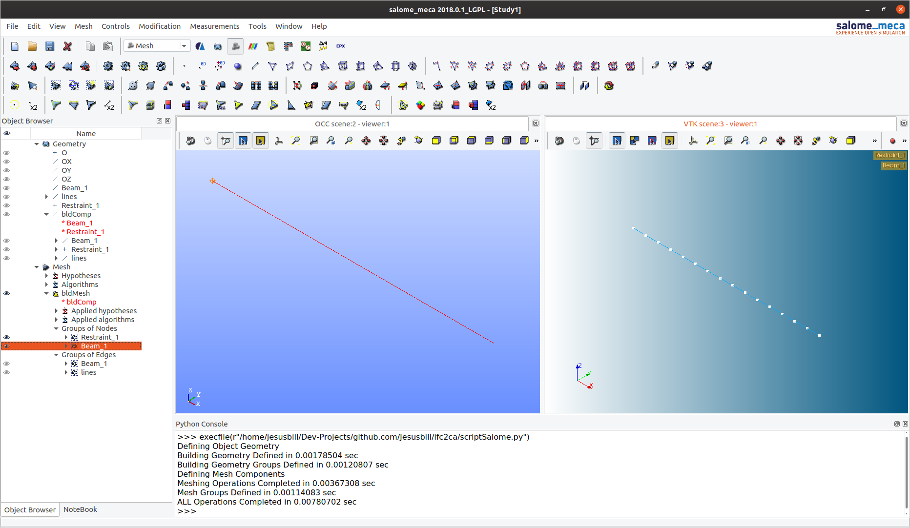
Running scriptSalome.py in _salome_meca_. View of Geometry and Mesh
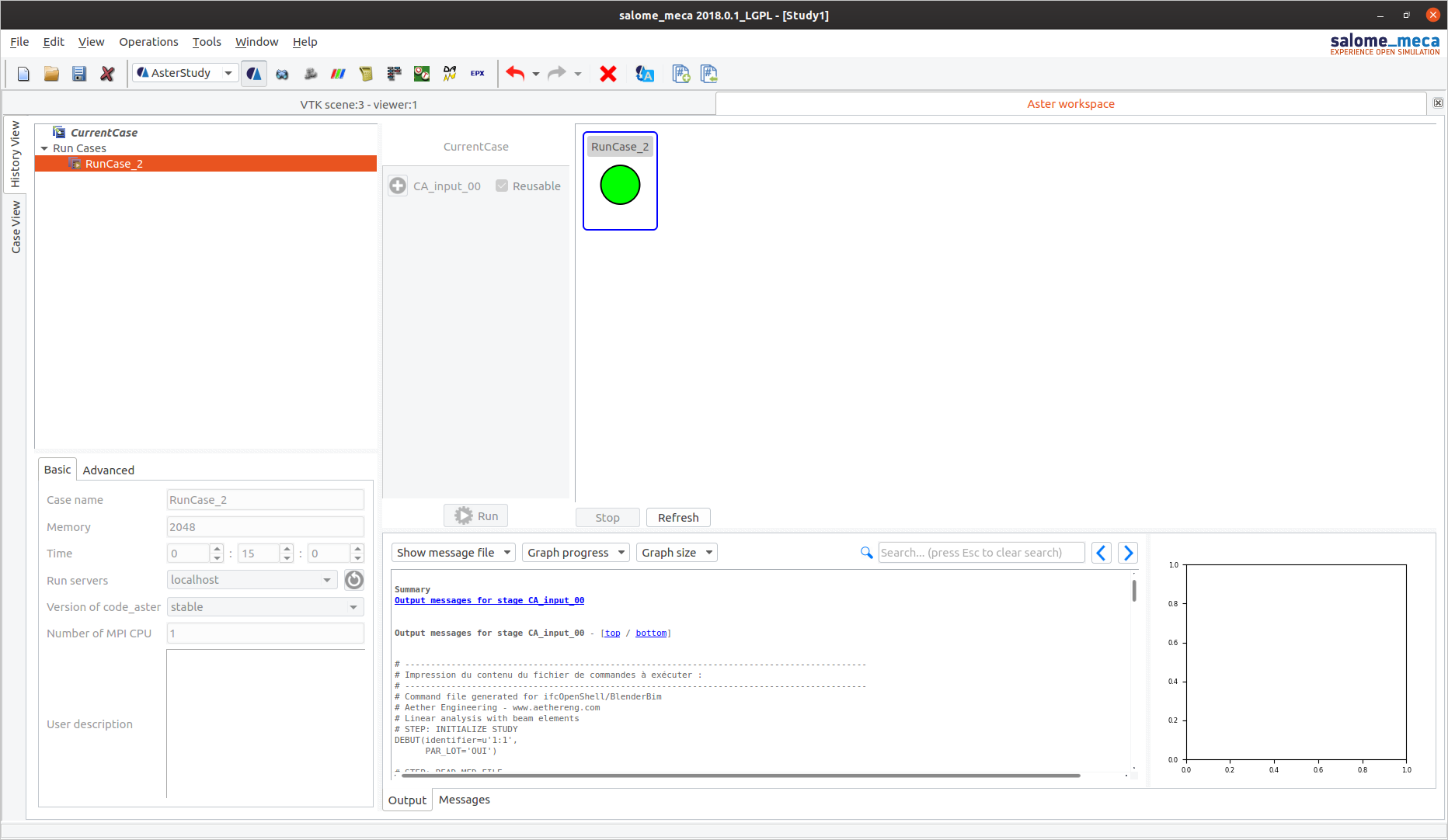
Importing the command file in _asterStudy_, the module with the UI to configure and run analyses with Code_Aster

Running the analysis always in _asterStudy_. Green light designates a successful execution
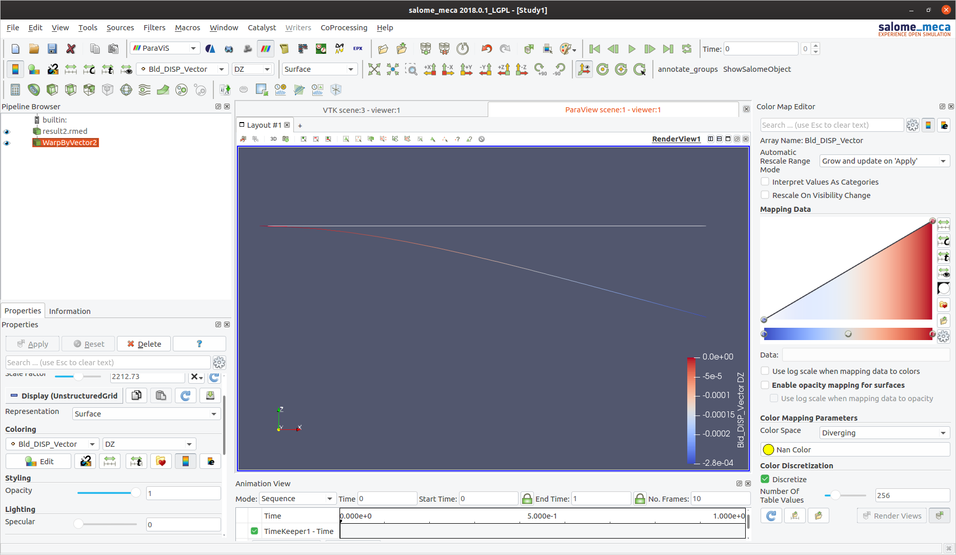
Viewing the results in _ParaViS_, the port of ParaView in the ecosystem
Jesusbill
on 22 Jan 2020
Woohoo! Thanks! Shall we try with a slightly more complex example? Perhaps:
- Again, single cantilevering beam, but now with a loading?
- Or perhaps two columns and a beam spanning between the columns?
Moult
on 22 Jan 2020
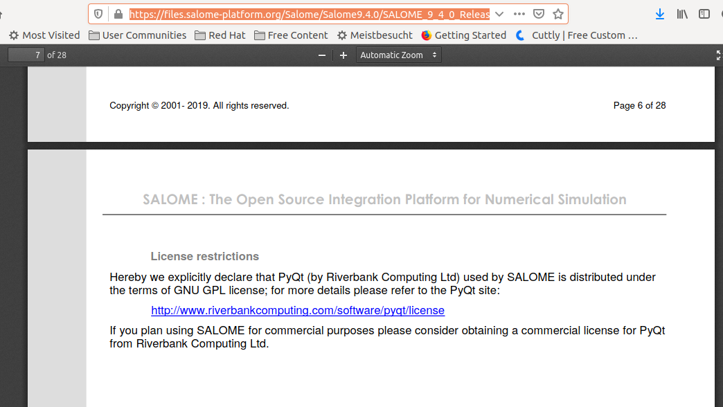
It is nice to have that functionality but be aware that salome_meca is not "fully free" for commercial projects. Check from s-m license (I am not a lawyer and it is not legal advice, just call for caution)
 ddjokic
on 24 Jan 2020
ddjokic
on 24 Jan 2020
Hi @Moult, here is the updated json file as agreed.
inputDataCA2.zip
Cheers
Jesusbill
on 3 Feb 2020
Closing issue, as the initial objective was a proof of concept which has now been achieved.
@Jesusbill - can you please start up a new thread on https://community.osarch.org/ about the integration of BlenderBIM, IFC, and Code_Aster? We can continue this work there. A few other developers of other free software related to the AEC industry had a little group email being passed around about how it would be a good idea to start a sort of "free software collective" for the AEC industry - and hence that forum was started up as there isn't really another community site for it. This is a perfect topic to develop further on the forum - especially as it benefits not just BlenderBIM, but all IFC tools :) Hopefully it works out.
Also I didn't really want to annoy the IfcOpenShell devs with email notifications about this which is isn't really about a bug :)
Moult
on 5 Feb 2020
Related issues
 aahoo
·
9Comments
Moult
·
7Comments
aahoo
·
9Comments
Moult
·
7Comments
 globalcitizen
·
10Comments
Moult
·
5Comments
globalcitizen
·
10Comments
Moult
·
5Comments
 Ahmed-Abdelhak
·
11Comments
Ahmed-Abdelhak
·
11Comments
Most helpful comment
Hi.
I'm very interested in this development. I'll take a look to the documents above. Thanks for the notice @berndhahnebach!