Hi all. How can I look to build a firmware for the following device:
https://www.amazon.co.uk/OurLeeme-Dimmer-Control-Function-Compatible/dp/B07RHCFKQ2
I have got one coming this week so I won't know what chip setup is inside but will post when I do. I wonder if the Sonoff wall dimmer will work as base code?
 davebuk
All 102 comments
@mcspr @xoseperez
Hi all. The device has arrived. Is it as simple as using a standard dimmer environment and changing the GPIO config, or does a separate environment need to be created?


UPDATE**

Pin locations if others need them. To flash, the fourth pin 'Flash' needs to be held at GND before power applied and kept at GND during flashing. I think it disables Tx/Rx communication to the MCU. You then need to boot with the GPIO 0 pin held to GND, then released a few seconds after boot. The Tx/Rx wires need to be connected directly to the TYWE3S pins.
davebuk
on 29 May 2019
Yes. Since you are just testing, anything with LIGHT dimmer would do. Just make sure to use 1MB environment
 mcspr
on 29 May 2019
mcspr
on 29 May 2019
Great, I'll have a go at the weekend. Is there a way to find out the GPIO assignments? Looking at the soldered board, GPIO 0, 14 and 15 are connected. I guess the on board button connects to 'RST' and maybe 0 for BOOT, so is the 'BUTTON' GPIO (not sure if this needs to be defined for the dimmer hardware).
Other than that, I also guess 14 / 15 control the two colour LED and the opposite one controls the dimmer output? One will be the 'LED' GPIO and the other will be the 'LIGHT' GPIO.
davebuk
on 30 May 2019
Use multimeter? Button thing is interesting, because it kind-of does different things - GPIO0 for flash / some SW button control, but RST will reset the chip itself. No software interaction there.
TX RX are going to the secondary MCU then? (or I am missing some turn)
mcspr
on 30 May 2019
The only measurement I got was 9K ohms from one of the ESP pins to one of the LED legs. Other resistances were around 2M ohm.
I need to work out which of the two header pins are TX and RX respectively, but 3v3 and ground are obvious. I guess the through hole header pin pads would be the ones to use for flashing, or should I take wires directly from the ESP chip Tx/ Rx connections?
Thanks.
davebuk
on 30 May 2019
Either way. I sure does look like tx rx are right there.
About dimming, it looks like manufacturer used Tuya SDK to set up the secondary controller. Tasmota repo already has an example of what it sends / receives:
https://docs.tuya.com/en/mcu/mcu-protocol.html
https://github.com/arendst/Sonoff-Tasmota/blob/development/sonoff/xdrv_16_tuyadimmer.ino
mcspr
on 30 May 2019
How do the dimming signals work for an espurna LED dimmer. Do they send signals using the Tx/Rx lines to a MCU which then controls the output drivers?
davebuk
on 30 May 2019
What I mean is we don't have LIGHT_PROVIDER for Tuya SDK dimmer variant (yet), if this thing uses serial communication with secondary MCU.
Most common LIGHT_PROVIDER_DIMMER generates PWM signal on gpio pin, which translates into brightness.
mcspr
on 31 May 2019
The two header solder pads that probably are TX/ Rx are not directly connected to the TX/ Rx of the ESP, they are connected to the 8500 chip below. I was unsure how the dimming was controlled using a single GPIO.
How long would it take to bring serial dimming into espurna? I may go and have a little play with tasmota for this device.
davebuk
on 31 May 2019
It would be useful to know if it is really using that serial protocol.
Something like this is already done for rfbridge, so at least writing Serial logic would not be a big problem. Basic idea that I got from the Tuya docs is that ESP should send out heartbeat messages when it boots (every 3s, flagged 0x00) and during normal operation (every 10s, flagged 0x01), then the second controller will accept commands / send out current state.
Another thing to do while it is wired is to download the original firmware .bin via esptool.py (0x100000 as size).
edit: baud setting may vary, maybe use 115200 to be safe
mcspr
on 31 May 2019
Trying to upload tasmota using pins on the board or pins wired directly to the TYWE3S fails. I don't get communication. Tried with button held at boot, button still held after boot, GPIO 0 to GND at boot and held to GND after boot with no success. The device is not in normal operation so it's doing something different at boot, plus the status LED flashes green after a few seconds then stays very dimly lit green.
I've not used esptool other than the espeasy GUI version to flash. I'll have to look at this over the next few days and see if I can first establish communication then get the current firmware extracted.
davebuk
on 31 May 2019
Is it the same with GPIO0? Not aware of GPIO2 operation, this wiki states that it needs to be high:
https://github.com/esp8266/esp8266-wiki/wiki/Boot-Process#esp-boot-modes
One thing ESP should always do when resetting is output lines like these on GPIO1 (TX), at 74880 speed:
pressing RST button on d1 mini when GPIO0 is pulled LOW
ets Jan 8 2013,rst cause:2, boot mode:(1,7)
pressing RST without anything connected
 ets Jan  8 2013,rst cause:2, boot mode:(3,7)

load 0x4010f000, len 1384, room 16
tail 8
chksum 0x2d
csum 0x2d
v8b899c12 < this is eboot from Arduino, after this line things are sw-specific
~ld
Sorry, meant GPIO 0 not 2, post above edited. Apologies!
davebuk
on 31 May 2019
I'm am having issues trying to confirm I have connection, but connected to ESP chip Tx/Rx and carrying out the above using putty I get:
ets Jan 8 2013,rst cause:2, boot mode:(1,2)
```
ets Jan 8 2013,rst cause:2, boot mode:(3,2)
load 0x40100000, len 2592, room 16
tail 0
chksum 0xf3
load 0x3ffe8000, len 764, room 8
tail 4
chksum 0x92
load 0x3ffe82fc, len 676, room 4
tail 0
chksum 0x22
csum 0x22
2nd boot version : 1.7(5d6f877)
SPI Speed : 40MHz
SPI Mode : QIO
SPI Flash Size & Map: 8Mbit(512KB+512KB)
jump to run user1 @ 1000
OS SDK ver: 2.0.0(e8c5810) compiled @ Jan 25 2019 14:26:04
phy ver: 1055_9, pp ver: 10.7
rf cal sector: 121
idle_task_hdl : 40107a90,prio:0, stack:384
tim_task_hdl : 40107bd8, prio:2,stack:512
```
davebuk
on 3 Jun 2019
But it works. Second log is non-Arduino bootloader, logging that it loaded the manufacturer's firmware. Which now can be safely backed up by esptoolpy and something else uploaded instead
mcspr
on 3 Jun 2019
I have tried
esptool.py -p COM3 -b 1155200 chip_id
and
esptool.py -p COM3 -b 115200 read_flash 0 0x100000 flash_contents.bin
after setting GPIO 0 to GND during boot and neither work. Constant time out errors. One time I had, invalid head of packet 0xff but can't get esptool.py chip_id to output anything.
davebuk
on 3 Jun 2019
Does it work without the -b ... param?
mcspr
on 3 Jun 2019
Nope. :-)
c:\Python27\Scripts>esptool.py -p COM3 read_flash 0 0x100000 flash_contents.bin
esptool.py v2.6
Serial port COM3
Connecting........_____....._____....._____....._____....._____....._____....._____

A fatal error occurred: Failed to connect to Espressif device: Timed out waiting for packet header

c:\Python27\Scripts>esptool.py -p COM3 chip_id
esptool.py v2.6
Serial port COM3
Connecting........_____....._____....._____....._____....._____....._____....._____

A fatal error occurred: Failed to connect to Espressif device: Timed out waiting for packet header

c:\Python27\Scripts>
Trying same thing on a Sonoff Basic V2 with espurna on gives:
c:\Python27\Scripts>esptool.py chip_id
esptool.py v2.6
Found 1 serial ports
Serial port COM3
Connecting....
Detecting chip type... ESP8266
Chip is ESP8285
Features: WiFi, Embedded Flash
MAC: 84:0d:8e:57:a1:15
Uploading stub...
Running stub...
Stub running...
Chip ID: 0x0057a115
Hard resetting via RTS pin...
Maybe slower? -b 9600 If it fails seemingly at random, maybe wiring is causing problems.
Putty can show boot mode, to make sure uploader mode is on. We want a single line with (1,...). Just make sure to disconnect putty before running esptool itself
mcspr
on 3 Jun 2019
No different at 9600. I'll do some more testing over the next few days and see what I can up with.
davebuk
on 3 Jun 2019
Got it. Using info from [(https://github.com/arendst/Sonoff-Tasmota/wiki/Tuya-Dimmer)], I connected GND to the forth header pin while booting and holding GPIO 0 to ground. I now have:
c:\Python27\Scripts>esptool.py chip_id
esptool.py v2.6
Found 1 serial ports
Serial port COM3
Connecting....
Detecting chip type... ESP8266
Chip is ESP8266EX
Features: WiFi
MAC: bc:dd:c2:a6:cc:bd
Uploading stub...
Running stub...
Stub running...
Chip ID: 0x00a6ccbd
Hard resetting via RTS pin...
Downloaded file is here:
flash_contents.zip
Thanks for your help. Am I ok to try Tasmota on this device now?
davebuk
on 3 Jun 2019
Yes. Thank you for the file! I just tried it with 1M dev board and see
the heartbeat on hw serial, as expected.
If you don't mind going slightly offtopic, can you try uploading some
basic (literally sonoff-basic should be ok for both espurna and tasmota) espurna image first? I was
not able to reproduce the issue from
https://github.com/xoseperez/espurna/issues/1663 and I wonder if
recent dev builds solved it or I am missing some other bug because of
espota.py usage. I tried upgrading via Web too, no problems :/
mcspr
on 4 Jun 2019
No problem. Just to be sure, you would like espurna dev uploaded via esptool then once initialised, try tasmota using espurna web OTA?
davebuk
on 4 Jun 2019
Correct. The test is if Tasmota sonoff.bin or sonoff-basic.bin work after updating from ESPurna via Web OTA
mcspr
on 4 Jun 2019
Working correctly for me. Uploaded a self built version of Sonoff Basic 1.13.6dev of espurna using esptool.py. Espurna boots correctly and I connected to my WiFi. Re-booted then used espurna OTA to flash Tasmota 'sonoff.bin'. Rebooted and device is now showing as sonoff device in wireless networks. Connected and setup Tasmota WiFi credentials and device is now connected to my WiFi and accessible using Tasmota web GUI.
Hope that is of some help?
davebuk
on 4 Jun 2019
The dimmer works with Tasmota using device configuration 'Tuya Dimmer 54'. ON/OFF toggle and dimming works using web GUI.
davebuk
on 4 Jun 2019
Great. Thanks for checking the OTA process!
Now the only thing left is to implement tuya dimmer module.
mcspr
on 4 Jun 2019
Thanks for your help. I've learnt alot over the past few days!
I'm sure it'll only take you a few days to implement the dimmer code for espurna! Let me know if I can help with any testing.
davebuk
on 4 Jun 2019
In addition to dimming, would the ability to dim using external push button or switch be viable. Ref #1331 ?
davebuk
on 5 Jun 2019
Button dimming is interesting in this context. idk why that pr never got split up. It got an important addition too - different scheduling method for transitions to make them more consistent.
Although, based on the documentation (and tuyadimmer tasmota code, again), that button is intended to reset wifi or all settings
Some things I've noticed after drafting a module for this at https://github.com/xoseperez/espurna/compare/dev...mcspr:experimental/tuya
(WARNING! will crash right now, guaranteed :)
- light update happens in ticker context and crashes instantly when doing serial writes. #1331 code pretty much describes what we need - add loop function with provider update
- default 10ms per transition between brightness levels is too fast for 9600 speed serial communication. so we either need to anticipate that and increase it proportionally, or add runtime setting to increase it, or turn it off completely for tuya.
- mcu can send gpio mapping and we need to update existing configuration. likely a speed-up for #1680
mcspr
on 8 Jun 2019
The 'button' option was to use spare GPIOs on the ESP and espurna software to allow extra external buttons for dimming control. I'm in the UK and here we don't normally have a 240V neutral at the light switches. I'd plan to fit one of these devices in the ceiling and have dimmer control using the two wires that come from the wall switch. They'd have to perhaps be configured so double press to brighten up and long press to dim down, with single press to toggle on/off.
From what I understand of the tuya docs and your knowledge, the ESP is only there to provide the interface to the outside world. The MCU does all the control via serial from the ESP, not GPIO pins. Like you said, even the physical button on the device must connect to the MCU rather than the ESP because holding it down at boot wouldn't let me flash it. I had to connect the ESP GPIO 0 to GND to get it to work (while the third header pin was also at GND throughout the flash).
davebuk
on 8 Jun 2019
There is some info here: https://www.letscontrolit.com/forum/viewtopic.php?t=5431
Not sure if it's of any use?
davebuk
on 8 Jun 2019
Oh. I was referencing what I read at https://docs.tuya.com/en/mcu/mcu-protocol.html#3query-the-working-mode-of-the-set-wi-fi-module, secondary chip can sometimes send real pin numbers. Just for compatibility sake, but we are not dealing with one of those here.
Long-press from the PR is a bit weird though. I think that was meant to go to the library code instead, probably need to add that there first... Double,triple,long click methods should work right now.
2nd link is interesting. Per the same doc latest section, functional protocol that sort-of matches length 8 and 4 byte value is "temperature", but the forum post got dpID 03 instead of 02.
https://www.letscontrolit.com/forum/viewtopic.php?t=5431#p31388
(which is later used as 2 for some reason, and back again)
55AA 00 06 0008 -> 03 <- 02 0004 00000038 4E
this hints as to why tasmota code remembers byte in that position from the data mcu sends out initially (as it looks like, documentation protocols are just examples)
Other documentation on the tuya website is in chinese and "mcu simulator" app I got excited about does need some kind of protocol description .json
edit: Example colorlights project does mention "brightness" value setter with the same dpID, so maybe that's where the manufacturer got that id
mcspr
on 9 Jun 2019
I have updated https://github.com/mcspr/espurna/tree/experimental/tuya with the tuya-generic-dimmer platformio env to build the firmware .bin
I think the communication is ok now, debugging rx/tx is on by default (tuyaDebug setting, 0/1).
Having re-read the documentation, I think 55aa0304000006 should be the packet for the button (aka wifi reset)? No handler for that yet, only DP config and switch / brightness commands from the ESP to the MCU.
mcspr
on 16 Jun 2019
Great work. I'll try and find some time later today to build and test.
davebuk
on 16 Jun 2019
I have built and uploaded using Tasmota minimal .bin then espurna firmare.bin via ota. The device first showed as an espurna-(chip ID) but with no security for the WiFi AP. After a power cycle, I was able to connect and login to the web GUI. Not sure if some Tasmota config was still partially loaded as my WiFi SSID was already there, just no password.
I can access the device via my WiFi but do not have any control of the output. Using 'info' in the debug section I get:
[571338] [WEBSOCKET] #5 connected, ip: 192.168.1.121, url: /ws
[574884] [TYUA] OUT: 55aa00000000ff
[574908] [TYUA] IN: 55aa000000010101
[574911] [TYUA] OUT: 55aa000300010407
[574935] [TYUA] IN: 55aa0003000002
[580406] [WEBSOCKET] Requested action: dbgcmd
[580415]

---8<-------

[580417] [MAIN] ESPURNA 1.13.6-dev
[580418] [MAIN] [email protected]
[580419] [MAIN] http://tinkerman.cat

[580422] [MAIN] CPU chip ID: 0xA6CCBD
[580424] [MAIN] CPU frequency: 80 MHz
[580424] [MAIN] SDK version: 1.5.3(aec24ac9)
[580425] [MAIN] Core version: 2.3.0
[580426] [MAIN] Core revision: 159542381
[580429] [MAIN] Build time: 1560706427
[580431]
[580432] [MAIN] Flash chip ID: 0x1440C8
[580437] [MAIN] Flash speed: 40000000 Hz
[580439] [MAIN] Flash mode: DOUT
[580441]
[580443] [MAIN] Flash size (CHIP)   :  1048576 bytes /  256 sectors (   0 to  255)
[580445] [MAIN] Flash size (SDK)    :  1048576 bytes /  256 sectors (   0 to  255)
[580447] [MAIN] Reserved            :     4096 bytes /    1 sectors (   0 to    0)
[580449] [MAIN] Firmware size       :   504320 bytes /  124 sectors (   1 to  124)
[580454] [MAIN] Max OTA size        :   253952 bytes /   62 sectors ( 125 to  186)
[580456] [MAIN] SPIFFS size         :   262144 bytes /   64 sectors ( 187 to  250)
[580458] [MAIN] EEPROM size         :     4096 bytes /    1 sectors ( 251 to  251)
[580460] [MAIN] Reserved            :    16384 bytes /    4 sectors ( 252 to  255)
[580463]
[580465] [MAIN] EEPROM sectors: 251, 250
[580466] [MAIN] EEPROM current: 250
[580467]
[580468] [MAIN] EEPROM:  4096 bytes initially |   996 bytes used (24%) |  3100 bytes free (75%)
[580469] [MAIN] Heap  : 33056 bytes initially | 18952 bytes used (57%) | 14104 bytes free (42%)
[580473] [MAIN] Stack :  4096 bytes initially |  1936 bytes used (47%) |  2160 bytes free (52%)
[580474]
[580477] [MAIN] Boot version: 31
[580479] [MAIN] Boot mode: 1
[580480] [MAIN] Last reset reason: Power on
[580482] [MAIN] Last reset info: flag: 0
[580484]
[580485] [MAIN] Board: TUYA_GENERIC_DIMMER
[580487] [MAIN] Support: ALEXA API BROKER BUTTON DEBUG_TELNET DEBUG_WEB DOMOTICZ HOMEASSISTANT LED MDNS_SERVER MQTT NTP SCHEDULER TELNET TERMINAL THINGSPEAK WEB
[580490] [MAIN] WebUI image: LIGHT
[580491]
[580492] [MAIN] Firmware MD5: e9c4025aa1b736841ffbffe0e1bbfc07
[580496] [MAIN] Power: 3190 mV
[580498] [MAIN] Power saving delay value: 10 ms
[580499]

---8<-------

[580500] +OK
[583887] [TYUA] OUT: 55aa00000000ff
[583912] [TYUA] IN: 55aa000000010101
[583914] [TYUA] OUT: 55aa000300010407
[583937] [TYUA] IN: 55aa0003000002
[592897] [TYUA] OUT: 55aa00000000ff
[592921] [TYUA] IN: 55aa000000010101
[592924] [TYUA] OUT: 55aa000300010407
[592947] [TYUA] IN: 55aa0003000002
[601899] [TYUA] OUT: 55aa00000000ff
[601923] [TYUA] IN: 55aa000000010101
[601926] [TYUA] OUT: 55aa000300010407
[601948] [TYUA] IN: 55aa0003000002
[610905] [TYUA] OUT: 55aa00000000ff
[610930] [TYUA] IN: 55aa000000010101
[610932] [TYUA] OUT: 55aa000300010407
[610955] [TYUA] IN: 55aa0003000002
[619908] [TYUA] OUT: 55aa00000000ff
[619932] [TYUA] IN: 55aa000000010101
[619935] [TYUA] OUT: 55aa000300010407
[619958] [TYUA] IN: 55aa0003000002
[628910] [TYUA] OUT: 55aa00000000ff
[628935] [TYUA] IN: 55aa000000010101
[628937] [TYUA] OUT: 55aa000300010407
[628960] [TYUA] IN: 55aa0003000002
The status page looks like:

After changing brightness on the status page I get:
[321009] [WEBSOCKET] Requested action: brightness
[321027] [TYUA] OUT: 55aa0006000803020004000000ff15
[322369] [TYUA] OUT: 55aa00000000ff
[322393] [TYUA] IN: 55aa000000010101
[322396] [TYUA] OUT: 55aa000300010407
[322418] [TYUA] IN: 55aa0003000002
[331377] [TYUA] OUT: 55aa00000000ff
[331401] [TYUA] IN: 55aa000000010101
[331404] [TYUA] OUT: 55aa000300010407
[331426] [TYUA] IN: 55aa0003000002
but the light is not controllable. It will toggle on and off by pressing the button on the device giving:
[442577] [TYUA] IN: 55aa00070008020200040000001026
[442579] [TUYA] Unknown DP id=2 type=2
[442591] [TYUA] IN: 55aa0007000501010001010f
[442614] [TYUA] IN: 55aa0007000802020004000000ff15
[442615] [TUYA] Unknown DP id=2 type=2
[445528] [TYUA] IN: 55aa0007000501010001000e
[445542] [TYUA] IN: 55aa0007000802020004000000ff15
[445545] [TUYA] Unknown DP id=2 type=2
[445557] [TYUA] IN: 55aa0007000501010001000e
[445569] [TYUA] IN: 55aa00070008020200040000001026
[445570] [TUYA] Unknown DP id=2 type=2
[448472] [TYUA] OUT: 55aa00000000ff
but again, the light cannot a adjusted in brightness from the web GUI.
Hope that is of some help?
davebuk
on 16 Jun 2019
It is a strange AP mode issue. I did notice some code in tasmota modifying SDK wifi settings storage on wifi disconnect, maybe that what causes it. But as you have noted, it goes away after reset because we modify it again.
Thank you for logs!
Brightness control must work after doing set tuyaDimmerDP 2 and rebooting, I have missed setSetting call somewhere in the queries but I got some new idea for that anyways.
And one virtual relay, I'll update the hardware config with 1 dummy relay and RELAY_PROVIDER_LIGHT
It is strange, however, that it sends 16 (55aa0007000802020004000000 --> 10 <-- 26) as OFF brightness value. But it would not matter, as relay would turn the light off first.
And I think I'll add tuya device description + discovered protocols to the info banners, so its not only displayed on boot.
Button does send anything different on double, triple or long presses?
mcspr
on 17 Jun 2019
I hadn't realised you had added that code. The following is single on/off, double, triple, off, 5 seconds held on, off, 10 seconds held on, off, 30 seconds held on, off.
For reference, the built in LED is off when off and RED when the light is on.
[616544] [WEBSOCKET] #8 connected, ip: 192.168.1.121, url: /ws
[623703] [TYUA] OUT: 55aa00000000ff
[623727] [TYUA] IN: 55aa000000010101
[623730] [TYUA] OUT: 55aa000300010407
[623752] [TYUA] IN: 55aa0003000002
[632704] [TYUA] OUT: 55aa00000000ff
[632728] [TYUA] IN: 55aa000000010101
[632731] [TYUA] OUT: 55aa000300010407
[632754] [TYUA] IN: 55aa0003000002
[641712] [TYUA] OUT: 55aa00000000ff
[641736] [TYUA] IN: 55aa000000010101
[641739] [TYUA] OUT: 55aa000300010407
[641762] [TYUA] IN: 55aa0003000002
[650722] [TYUA] OUT: 55aa00000000ff
[650746] [TYUA] IN: 55aa000000010101
[650749] [TYUA] OUT: 55aa000300010407
[650771] [TYUA] IN: 55aa0003000002
[659727] [TYUA] OUT: 55aa00000000ff
[659752] [TYUA] IN: 55aa000000010101
[659755] [TYUA] OUT: 55aa000300010407
[659778] [TYUA] IN: 55aa0003000002
[668022] [TYUA] IN: 55aa0007000501010001010f
[668046] [TYUA] IN: 55aa00070008020200040000001026
[668049] [TUYA] Unknown DP id=2 type=2
[668050] [TYUA] IN: 55aa0007000501010001010f
[668074] [TYUA] IN: 55aa0007000802020004000000ff15
[668076] [TUYA] Unknown DP id=2 type=2
[668731] [TYUA] OUT: 55aa00000000ff
[668755] [TYUA] IN: 55aa000000010101
[668758] [TYUA] OUT: 55aa000300010407
[668781] [TYUA] IN: 55aa0003000002
[669466] [TYUA] IN: 55aa0007000501010001000e
[669480] [TYUA] IN: 55aa0007000802020004000000ff15
[669482] [TUYA] Unknown DP id=2 type=2
[669495] [TYUA] IN: 55aa0007000501010001000e
[669509] [TYUA] IN: 55aa00070008020200040000001026
[669511] [TUYA] Unknown DP id=2 type=2
[670643] [TYUA] IN: 55aa0007000501010001010f
[670667] [TYUA] IN: 55aa00070008020200040000001026
[670670] [TUYA] Unknown DP id=2 type=2
[670672] [TYUA] IN: 55aa0007000501010001010f
[670695] [TYUA] IN: 55aa0007000802020004000000ff15
[670697] [TUYA] Unknown DP id=2 type=2
[670954] [TYUA] IN: 55aa0007000501010001000e
[670979] [TYUA] IN: 55aa0007000802020004000000ff15
[670981] [TUYA] Unknown DP id=2 type=2
[670983] [TYUA] IN: 55aa0007000501010001000e
[671006] [TYUA] IN: 55aa00070008020200040000001026
[671008] [TUYA] Unknown DP id=2 type=2
[672027] [TYUA] IN: 55aa0007000501010001010f
[672041] [TYUA] IN: 55aa00070008020200040000001026
[672044] [TUYA] Unknown DP id=2 type=2
[672056] [TYUA] IN: 55aa0007000501010001010f
[672070] [TYUA] IN: 55aa0007000802020004000000ff15
[672072] [TUYA] Unknown DP id=2 type=2
[672482] [TYUA] IN: 55aa0007000501010001000e
[672496] [TYUA] IN: 55aa0007000802020004000000ff15
[672499] [TUYA] Unknown DP id=2 type=2
[672511] [TYUA] IN: 55aa0007000501010001000e
[672524] [TYUA] IN: 55aa00070008020200040000001026
[672526] [TUYA] Unknown DP id=2 type=2
[672895] [TYUA] IN: 55aa0007000501010001010f
[672910] [TYUA] IN: 55aa00070008020200040000001026
[672913] [TUYA] Unknown DP id=2 type=2
[672925] [TYUA] IN: 55aa0007000501010001010f
[672939] [TYUA] IN: 55aa0007000802020004000000ff15
[672941] [TUYA] Unknown DP id=2 type=2
[675774] [TYUA] IN: 55aa0007000501010001000e
[675788] [TYUA] IN: 55aa0007000802020004000000ff15
[675791] [TUYA] Unknown DP id=2 type=2
[675803] [TYUA] IN: 55aa0007000501010001000e
[675816] [TYUA] IN: 55aa00070008020200040000001026
[675819] [TUYA] Unknown DP id=2 type=2
[677617] [TYUA] IN: 55aa0007000501010001010f
[677631] [TYUA] IN: 55aa00070008020200040000001026
[677634] [TUYA] Unknown DP id=2 type=2
[677646] [TYUA] IN: 55aa0007000501010001010f
[677661] [TYUA] IN: 55aa0007000802020004000000ff15
[677664] [TUYA] Unknown DP id=2 type=2
[677738] [TYUA] OUT: 55aa00000000ff
[677761] [TYUA] IN: 55aa000000010101
[677764] [TYUA] OUT: 55aa000300010407
[677787] [TYUA] IN: 55aa0003000002
[684085] [TYUA] IN: 55aa0007000501010001000e
[684099] [TYUA] IN: 55aa0007000802020004000000ff15
[684101] [TUYA] Unknown DP id=2 type=2
[684114] [TYUA] IN: 55aa0007000501010001000e
[684129] [TYUA] IN: 55aa00070008020200040000001026
[684132] [TUYA] Unknown DP id=2 type=2
[685892] [TYUA] IN: 55aa0007000501010001010f
[685916] [TYUA] IN: 55aa00070008020200040000001026
[685919] [TUYA] Unknown DP id=2 type=2
[685921] [TYUA] IN: 55aa0007000501010001010f
[685944] [TYUA] IN: 55aa0007000802020004000000ff15
[685945] [TUYA] Unknown DP id=2 type=2
[686743] [TYUA] OUT: 55aa00000000ff
[686767] [TYUA] IN: 55aa000000010101
[686770] [TYUA] OUT: 55aa000300010407
[686793] [TYUA] IN: 55aa0003000002
[695752] [TYUA] OUT: 55aa00000000ff
[695776] [TYUA] IN: 55aa000000010101
[695779] [TYUA] OUT: 55aa000300010407
[695802] [TYUA] IN: 55aa0003000002
[698344] [TYUA] IN: 55aa0007000501010001000e
[698358] [TYUA] IN: 55aa0007000802020004000000ff15
[698361] [TUYA] Unknown DP id=2 type=2
[698373] [TYUA] IN: 55aa0007000501010001000e
[698386] [TYUA] IN: 55aa00070008020200040000001026
[698388] [TUYA] Unknown DP id=2 type=2
[699895] [TYUA] IN: 55aa0007000501010001010f
[699909] [TYUA] IN: 55aa00070008020200040000001026
[699911] [TUYA] Unknown DP id=2 type=2
[699924] [TYUA] IN: 55aa0007000501010001010f
[699938] [TYUA] IN: 55aa0007000802020004000000ff15
[699941] [TUYA] Unknown DP id=2 type=2
[704754] [TYUA] OUT: 55aa00000000ff
[704778] [TYUA] IN: 55aa000000010101
[704781] [TYUA] OUT: 55aa000300010407
[704804] [TYUA] IN: 55aa0003000002
[713756] [TYUA] OUT: 55aa00000000ff
[713780] [TYUA] IN: 55aa000000010101
[713783] [TYUA] OUT: 55aa000300010407
[713806] [TYUA] IN: 55aa0003000002
[720252] [TYUA] IN: 55aa0007000501010001000e
[720266] [TYUA] IN: 55aa0007000802020004000000ff15
[720268] [TUYA] Unknown DP id=2 type=2
[720282] [TYUA] IN: 55aa0007000501010001000e
[720294] [TYUA] IN: 55aa00070008020200040000001026
[720295] [TUYA] Unknown DP id=2 type=2
[722766] [TYUA] OUT: 55aa00000000ff
[722790] [TYUA] IN: 55aa000000010101
[722793] [TYUA] OUT: 55aa000300010407
[722816] [TYUA] IN: 55aa0003000002
[731772] [TYUA] OUT: 55aa00000000ff
[731796] [TYUA] IN: 55aa000000010101
[731799] [TYUA] OUT: 55aa000300010407
[731823] [TYUA] IN: 55aa0003000002
[740780] [TYUA] OUT: 55aa00000000ff
[740804] [TYUA] IN: 55aa000000010101
[740807] [TYUA] OUT: 55aa000300010407
[740830] [TYUA] IN: 55aa0003000002
[749784] [TYUA] OUT: 55aa00000000ff
[749808] [TYUA] IN: 55aa000000010101
[749811] [TYUA] OUT: 55aa000300010407
[749834] [TYUA] IN: 55aa0003000002
[758789] [TYUA] OUT: 55aa00000000ff
[758814] [TYUA] IN: 55aa000000010101
[758817] [TYUA] OUT: 55aa000300010407
[758840] [TYUA] IN: 55aa0003000002
On a side note, after flashing using the Tasmota minimal, then espurna 493KB .bin file, I only have 258048 bytes free for an OTA update. I guess using the two step method with Tasmota has re-sized the flash memory? Can I get back to two 512KB halves using OTA uploads or will I just need to erase/upload espurna using the serial ports?
davebuk
on 17 Jun 2019
Button does not seem to do anything other than sending brightness 0 to 255 and back, switch ON OFF.
What does the paper manual say about wifi modes? I did find one example: https://fccid.io/ZZH-WF500D/User-Manual/Users-Manual-3846958
Pressing 5 times in a row and holding 6th should trigger WiFi config? Maybe that will work?
That flash size issue is my bad, I copied the build flags string from the other wemos board which also had it wrong. It should be ${common.build_flags_1m0m} instead of ${common.build_flags}. With platformio defaults we reserve 256Kb for SPIFFS and can't use that space for firmware. No way to OTA upgrade I'm afraid, It will reject firmware based on size first, not looking at the new flash layout.
mcspr
on 17 Jun 2019
The manuals says that if the devices doesn't boot with a rapidly flashing LED, hold the button down for 15 seconds and confirm the LED is now flashing rapidly.
Pressing 5 times and holding on the sixth gives:
[421641] [TYUA] OUT: 55aa00000000ff
[421664] [TYUA] IN: 55aa000000010101
[421666] [TYUA] OUT: 55aa000300010407
[421689] [TYUA] IN: 55aa0003000002
[430649] [TYUA] OUT: 55aa00000000ff
[430674] [TYUA] IN: 55aa000000010101
[430678] [TYUA] OUT: 55aa000300010407
[430701] [TYUA] IN: 55aa0003000002
[437921] [TYUA] IN: 55aa0007000501010001010f
[437934] [TYUA] IN: 55aa00070008020200040000001026
[437936] [TUYA] Unknown DP id=2 type=2
[437947] [TYUA] IN: 55aa0007000501010001010f
[437970] [TYUA] IN: 55aa0007000802020004000000ff15
[437971] [TUYA] Unknown DP id=2 type=2
[438453] [TYUA] IN: 55aa0007000501010001000e
[438468] [TYUA] IN: 55aa0007000802020004000000ff15
[438470] [TUYA] Unknown DP id=2 type=2
[438483] [TYUA] IN: 55aa0007000501010001000e
[438495] [TYUA] IN: 55aa00070008020200040000001026
[438496] [TUYA] Unknown DP id=2 type=2
[438999] [TYUA] IN: 55aa0007000501010001010f
[439013] [TYUA] IN: 55aa00070008020200040000001026
[439014] [TUYA] Unknown DP id=2 type=2
[439026] [TYUA] IN: 55aa0007000501010001010f
[439041] [TYUA] IN: 55aa0007000802020004000000ff15
[439042] [TUYA] Unknown DP id=2 type=2
[439535] [TYUA] IN: 55aa0007000501010001000e
[439559] [TYUA] IN: 55aa0007000802020004000000ff15
[439562] [TUYA] Unknown DP id=2 type=2
[439563] [TYUA] IN: 55aa0007000501010001000e
[439588] [TYUA] IN: 55aa00070008020200040000001026
[439591] [TUYA] Unknown DP id=2 type=2
[439654] [TYUA] OUT: 55aa00000000ff
[439678] [TYUA] IN: 55aa000000010101
[439681] [TYUA] OUT: 55aa000300010407
[439704] [TYUA] IN: 55aa0003000002
[440105] [TYUA] IN: 55aa0007000501010001010f
[440118] [TYUA] IN: 55aa00070008020200040000001026
[440120] [TUYA] Unknown DP id=2 type=2
[440131] [TYUA] IN: 55aa0007000501010001010f
[440153] [TYUA] IN: 55aa0007000802020004000000ff15
[440157] [TUYA] Unknown DP id=2 type=2
[440640] [TYUA] IN: 55aa0007000501010001000e
[440654] [TYUA] IN: 55aa0007000802020004000000ff15
[440655] [TUYA] Unknown DP id=2 type=2
[440667] [TYUA] IN: 55aa0007000501010001000e
[440678] [TYUA] IN: 55aa00070008020200040000001026
[440679] [TUYA] Unknown DP id=2 type=2
[448658] [TYUA] OUT: 55aa00000000ff
[448682] [TYUA] IN: 55aa000000010101
[448683] [TYUA] OUT: 55aa000300010407
[448705] [TYUA] IN: 55aa0003000002
Does it matter in the output code it says [TYUA] rather than [TUYA]?
When you are ready, let me know when to try building the next test version.
davebuk
on 17 Jun 2019
I was expecting to see either 55aa0004... or 55aa0005... somewhere. Huh. Maybe the 15 second hold would send it. And TYUA thing is just a misspelling in the logging method 🤷♂
Will do. I want to try to replace static switch / light config with some dynamic detection.
ot. researching some other tuya modules, they can be pretty expressive: https://blakadder.github.io/templates/oil_diffuser_550ml.html
mcspr
on 18 Jun 2019
@mcspr Have you found any time to look any more into the code? The external button press for dimming is not something I need for my current application, it was just a nice to have.
Do you have any working code that will enable power toggle using the built in switch and on/off and dimming control using MQTT?
davebuk
on 2 Jul 2019
I'll try to come up with something mergeable this week.
Current tree is not working, but I did include the relay definition and flash layout fix 2 weeks ago:
https://github.com/mcspr/espurna/commit/bca19f4eab5c3702404b6a9b878911e4711b60dc
Have you tried setting additional params in the terminal for the previous running build (bc last message shows Unknown DP id=2 type=2, including reboot to apply)?
set tuyaDimmerDP 2
set useTransitions 0
First one will apply the correct message DP, so both In and Out messages are parsed by both sides (e.g. 55aa00070008020200040000001026). Second one I think is optional, it disables transitions if they look strange.
mcspr
on 2 Jul 2019
Failed to build, /code/espurna/tuya.ino:23:27: fatal error: tuya_protocol.h: No such file or directory
Unless I'm looking in the wrong place, I can't find tuya_protocol.h
davebuk
on 3 Jul 2019
It's not commited yet, note "not working" part. :) I have not tested that thing yet, but uploaded part of it as a backup.
If you want just the fix mentioned above, git checkout <commit hash> (add -b ... to checkout into a separate branch)
mcspr
on 3 Jul 2019
Sorry, my misunderstanding ;-) I'll wait until you have the code ready to merge. I am currently running the tasmota firmware so no rush.
Thanks again.
davebuk
on 3 Jul 2019
I have updated the experimental branch with protocol discovery and better (hopefully!) relay / channel interactions.
Based on the logs above, we are using 1 light channel and 1 switch that controls it.
Discovery should work out configuration for both. If not:
set tuyaSwitch0 1
set tuyaChannel0 2
reset
I tried with what I think discovery looks like and the config above.
edit: Additional terminal commands
tuya.show displays current configuration
tuya.save in case of discovery, this will save current configuration to flash
Sidenote: while there is no Serial logging here, it can be remedied by using Serial1 (GPIO2 aka TX1, no RX there):
-DDEBUG_PORT=Serial1 -DDEBUG_SERIAL_SUPPORT=1
It would be interesting to see early boot logs.
mcspr
on 7 Jul 2019
Looking good so far. :-)
After initial wifi setup etc the connected light was on and the button toggle switch switched the light off but after a second or so, it came back on, repeatedly. Using the web GUI I had a toggle switch and after selecting On/Off, the software and hardware button worked. The slight problem is that when selecting ON, the brightness changes to '1', so it looks like the light is off.
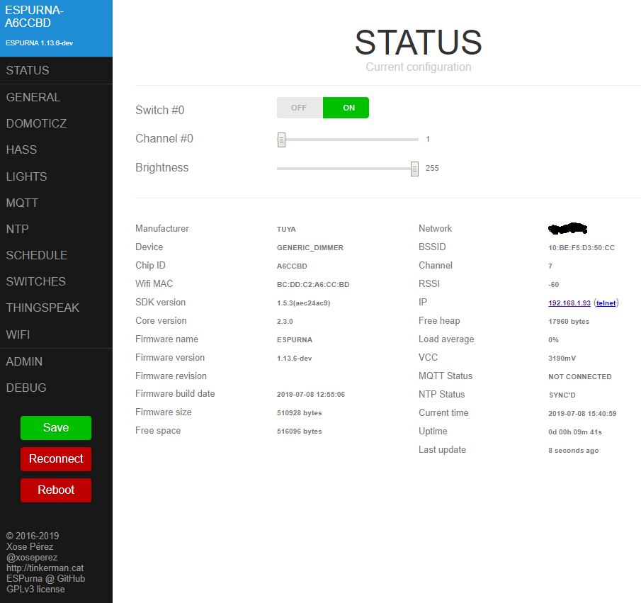
Brightness
From the GUI I can then change the brightness up and down so the light is actually on and changing values. Every time change the brightness of Channel #0, it then jumps up to that value shown plus another 16 (e.g. set brightness to 200, it shows 200 then jumps to 216).
ON/OFF Toggle
I then rebooted from the GUI to get boot debugging info. This time I didn't have the ON/OFF toggle, but moving the #0 slider turned the light on and adjusted the brightness. By using the three configuration commands above and rebooting brought the switch back.
Post boot
[012012] [TUYA] OUT: 55aa00000000ff
[012036] [TUYA] IN: 55aa000000010101
[013472] [NTP] UTC Time  : 2019-07-08 13:31:24
[013473] [NTP] Local Time: 2019-07-08 15:31:24
[021020] [TUYA] OUT: 55aa00000000ff
[021044] [TUYA] IN: 55aa000000010101
[030021] [TUYA] OUT: 55aa00000000ff
[030045] [TUYA] IN: 55aa000000010101
[039027] [TUYA] OUT: 55aa00000000ff
[039050] [TUYA] IN: 55aa000000010101
[048034] [TUYA] OUT: 55aa00000000ff
[048057] [TUYA] IN: 55aa000000010101
[057035] [TUYA] OUT: 55aa00000000ff
[057059] [TUYA] IN: 55aa000000010101
[060007] [MAIN] System OK
[066036] [TUYA] OUT: 55aa00000000ff
[066060] [TUYA] IN: 55aa000000010101
[075045] [TUYA] OUT: 55aa00000000ff
[075069] [TUYA] IN: 55aa000000010101
Some ON/OFF commands
[796602] [WEBSOCKET] Requested action: relay
[796604] [RELAY] #0 scheduled OFF in 0 ms
[796606] [RELAY] #0 set to OFF
[796609] [TUYA] OUT: 55aa0006000501010001000d
[796646] [TUYA] IN: 55aa0007000501010001000e
[796660] [TUYA] IN: 55aa0007000501010001000e
[796673] [TUYA] IN: 55aa00070008020200040000001026
[797608] [RELAY] Setting relay mask: 0
[799607] [WEBSOCKET] Requested action: relay
[799609] [RELAY] #0 scheduled ON in 0 ms
[799611] [RELAY] #0 set to ON
[799615] [TUYA] OUT: 55aa0006000501010001010e
[799627] [TUYA] OUT: 55aa00060008020200040000000116
[799651] [TUYA] IN: 55aa0007000501010001010f
[799663] [TUYA] IN: 55aa0007000501010001010f
[799675] [TUYA] IN: 55aa00070008020200040000001026
[799691] [TUYA] IN: 55aa00070008020200040000000117
[800613] [RELAY] Setting relay mask: 1
[801616] [WEBSOCKET] Requested action: relay
[801618] [RELAY] #0 scheduled OFF in 0 ms
[801624] [RELAY] #0 set to OFF
[801631] [TUYA] OUT: 55aa0006000501010001000d
[801664] [TUYA] IN: 55aa0007000501010001000e
[801676] [TUYA] IN: 55aa0007000501010001000e
[801688] [TUYA] IN: 55aa00070008020200040000001026
[802627] [RELAY] Setting relay mask: 0
[803421] [WEBSOCKET] Requested action: relay
[803424] [RELAY] #0 scheduled ON in 0 ms
[803425] [RELAY] #0 set to ON
[803429] [TUYA] OUT: 55aa0006000501010001010e
[803441] [TUYA] OUT: 55aa00060008020200040000000116
[803464] [TUYA] IN: 55aa0007000501010001010f
[803476] [TUYA] IN: 55aa0007000501010001010f
[803488] [TUYA] IN: 55aa00070008020200040000001026
[803501] [TUYA] IN: 55aa00070008020200040000000117
[804388] [TUYA] OUT: 55aa00000000ff
[804411] [TUYA] IN: 55aa000000010101
[804428] [RELAY] Setting relay mask: 1
[804542] [WEBSOCKET] Requested action: relay
[804545] [RELAY] #0 scheduled OFF in 0 ms
[804548] [RELAY] #0 set to OFF
[804554] [TUYA] OUT: 55aa0006000501010001000d
[804588] [TUYA] IN: 55aa0007000501010001000e
[804600] [TUYA] IN: 55aa0007000501010001000e
[804612] [TUYA] IN: 55aa00070008020200040000001026
[805553] [RELAY] Setting relay mask: 0
[813392] [TUYA] OUT: 55aa00000000ff
[813416] [TUYA] IN: 55aa000000010101
Brightness changes
[917941] [WEBSOCKET] Requested action: relay
[917943] [RELAY] #0 scheduled ON in 0 ms
[917946] [RELAY] #0 set to ON
[917953] [TUYA] OUT: 55aa0006000501010001010e
[917965] [TUYA] OUT: 55aa00060008020200040000000116
[917988] [TUYA] IN: 55aa0007000501010001010f
[918000] [TUYA] IN: 55aa0007000501010001010f
[918012] [TUYA] IN: 55aa00070008020200040000001026
[918027] [TUYA] IN: 55aa00070008020200040000000117
[918952] [RELAY] Setting relay mask: 1
[921009] [WEBSOCKET] Requested action: channel
[921116] [TUYA] OUT: 55aa00060008020200040000008499
[921161] [TUYA] IN: 55aa0007000802020004000000849a
[921162] [TUYA] IN: 55aa0007000501010001010f
[921185] [TUYA] IN: 55aa000700080202000400000094aa
[921458] [TUYA] OUT: 55aa00000000ff
[921481] [TUYA] IN: 55aa000000010101
[923591] [WEBSOCKET] Requested action: channel
[923698] [TUYA] OUT: 55aa0006000802020004000000bed3
[923741] [TUYA] IN: 55aa0007000802020004000000bed4
[923754] [TUYA] IN: 55aa0007000501010001010f
[923767] [TUYA] IN: 55aa0007000802020004000000cce2
[926536] [WEBSOCKET] Requested action: channel
[926643] [TUYA] OUT: 55aa00060008020200040000004055
[926687] [TUYA] IN: 55aa00070008020200040000004056
[926699] [TUYA] IN: 55aa0007000501010001010f
[926713] [TUYA] IN: 55aa00070008020200040000004e64
[930459] [TUYA] OUT: 55aa00000000ff
The brightness change can be seen below in the MQTT output.
[415957] [MQTT] Sending TUYA001/relay/0 => 1 (PID 1)
[415963] [TUYA] OUT: 55aa0006000501010001010e
[415976] [TUYA] OUT: 55aa00060008020200040000000116
[415998] [TUYA] IN: 55aa0007000501010001010f
[416010] [TUYA] IN: 55aa0007000501010001010f
[416025] [TUYA] IN: 55aa00070008020200040000001026
[416038] [TUYA] IN: 55aa00070008020200040000000117
[416144] [MQTT] Sending TUYA001/channel/0 => 1 (PID 1)
[416146] [MQTT] Sending TUYA001/brightness => 255 (PID 1)
[416671] [TUYA] OUT: 55aa00000000ff
[416695] [TUYA] IN: 55aa000000010101
[416962] [RELAY] Setting relay mask: 1
[419888] [WEBSOCKET] Requested action: channel
[419991] [MQTT] Sending TUYA001/channel/0 => 56 (PID 1)
[419993] [MQTT] Sending TUYA001/brightness => 255 (PID 1)
[419996] [TUYA] OUT: 55aa0006000802020004000000384d
[420031] [TUYA] IN: 55aa0007000802020004000000384e
[420043] [TUYA] IN: 55aa0007000501010001010f
[420067] [TUYA] IN: 55aa0007000802020004000000485e
[420170] [MQTT] Sending TUYA001/channel/0 => 72 (PID 1)
[420172] [MQTT] Sending TUYA001/brightness => 255 (PID 1)
[561436] [WEBSOCKET] Requested action: relay
[561438] [RELAY] #0 scheduled OFF in 0 ms
[561440] [RELAY] #0 set to OFF
[561442] [MQTT] Sending TUYA001/relay/0 => 0 (PID 1)
[561449] [TUYA] OUT: 55aa0006000501010001000d
[561482] [TUYA] IN: 55aa0007000501010001000e
[561495] [TUYA] IN: 55aa0007000501010001000e
[561506] [TUYA] IN: 55aa0007000802020004000000485e
[561520] [TUYA] IN: 55aa0007000501010001000e
[561533] [TUYA] IN: 55aa00070008020200040000001026
[561636] [MQTT] Sending TUYA001/channel/0 => 0 (PID 1)
[561638] [MQTT] Sending TUYA001/brightness => 255 (PID 1)
[562444] [RELAY] Setting relay mask: 0


md5-ee67480c19a3a44b3a64659ed52e15ec


[093190] [WEBSOCKET] Requested action: dbgcmd
[093194] [TUYA] BOOL
[093195] tuyaSwitch0=1 value=ON
[093195] [TUYA] INT
[093196] tuyaChannel0=2 value=78
This corresponded with the values on the web 'Status' page.
davebuk
on 8 Jul 2019
After initial wifi setup etc the connected light was on and the button toggle switch switched the light off but after a second or so, it came back on, repeatedly. Using the web GUI I had a toggle switch and after selecting On/Off, the software and hardware button worked. The slight problem is that when selecting ON, the brightness changes to '1', so it looks like the light is off.
Thank you for checking that out!
Does the device remember the last state all by itself and web shown switch as ON initially? And without touching real button (I got that right?), UI / MQTT switching did work initially?
Regarding the switch loop, did it log "[RELAY] #0 scheduled ..." etc. while this was happening? I got a vague idea why it may desync because of the channel offset situation that you describe.
Every time change the brightness of Channel #0, it then jumps up to that value shown plus another 16 (e.g. set brightness to 200, it shows 200 then jumps to 216).
This is real strange thing. Looking at logs, sending 1 (0x1) results in it returning 16 (0x10) and immediately reporting 1 (0x1) again. Or another example:
[419996] [TUYA] OUT: 55aa0006000802020004000000 -> 38 <- 4d // setting channel slider to 56
[420031] [TUYA] IN: 55aa0007000802020004000000 -> 38 <- 4e // MCU acknowledges (as documented)
[420043] [TUYA] IN: 55aa0007000501010001 -> 01 <- 0f // light is ON (so should be the switch toggle)
[420067] [TUYA] IN: 55aa0007000802020004000000 -> 48 <- 5e // MCU reports brightness 72 (what?)
But what happens with full channel brightness 255 (0xFF) or near it? Terminal has channel 0 <value>
I then rebooted from the GUI to get boot debugging info. This time I didn't have the ON/OFF toggle, but moving the #0 slider turned the light on and adjusted the brightness.
This is strange too. It does slightly different things because other MCU is not powered down, but nothing specific to make switch go missing... Will test this more closely. You sure that the switch did not come up after page reload?
Did it loop because of hardware button toggle is this state?
mcspr
on 8 Jul 2019
https://github.com/xoseperez/espurna/issues/1729#issuecomment-496889121
Pin locations if others need them. To flash, the fourth pin needs to be held at GND before power applied and kept at GND during flashing. I think it disables Tx/Rx communication to the MCU. You then need to boot with the GPIO 0 pin held to GND, then release a few seconds after boot. The Tx/Rx wires need to be connected directly to the TYWE3S pins. Flash using which ever method you prefer.
GPIO0 is up 2 pins, based on this https://docs.tuya.com/en/hardware/WiFi-module/wifi-e3s-module.html#21-dimensions
The N/C between 15 and 0 is the TX1 (Serial1) which can be used to debug really early boot
(or I can add a buffer for all debug output during that time... which may help to debug reboot situation too)
mcspr
on 8 Jul 2019
Does the device remember the last state all by itself and web shown switch as ON initially? And without touching real button (I got that right?), UI / MQTT switching did work initially?
Yes, switch all works as you would expect and it tries to switch back on at the previous level. When selected to OFF, the channel#0 goes to 16, MQTT reports 0. When selected back ON, the light very briefly flicks to somewhere near the previous value e.g 120 or 255 etc but then jumps straight to 1 with MQTT reporting 1. The light is still represented as ON just extremely dim (can't tell if ON or OFF) but the red LED on the device is still on which follows the ON/OFF commands.
Regarding the switch loop, did it log "[RELAY] #0 scheduled ..." etc. while this was happening? I got a vague idea why it may desync because of the channel offset situation that you describe.
Unfortunately I didn't see those logs.
This is real strange thing. Looking at logs, sending 1 (0x1) results in it returning 16 (0x10) and immediately reporting 1 (0x1) again. Or another example:
Whats even more strange, regardless of ON/OFF state, doing a full power cycle (not software reboot), a second switch and channel value are set. tuya.show gives:
[861777] [WEBSOCKET] Requested action: dbgcmd
[861780] [TUYA] BOOL
[861781] tuyaSwitch0=1 value=ON
[861782] tuyaSwitch1=1 value=ON
[861782] [TUYA] INT
[861783] tuyaChannel0=2 value=165
[861783] tuyaChannel1=2 value=150
These are switch#1 and channel#1. s#0 is independent of s#1 but s#1 makes s#0 follow after a few seconds. Adjusting the brightness of c#1 gives a value which does not jump by 16, then a few seconds later c#0 follows c#1 with the value plus 16. To note, the brightness slider has no effect and never changes from 255. Power cycling again doesn't try to add a third switch or delete the second, only using the following resets back to one switch and channel.
set tuyaSwitch0 1
set tuyaChannel0 2
reset
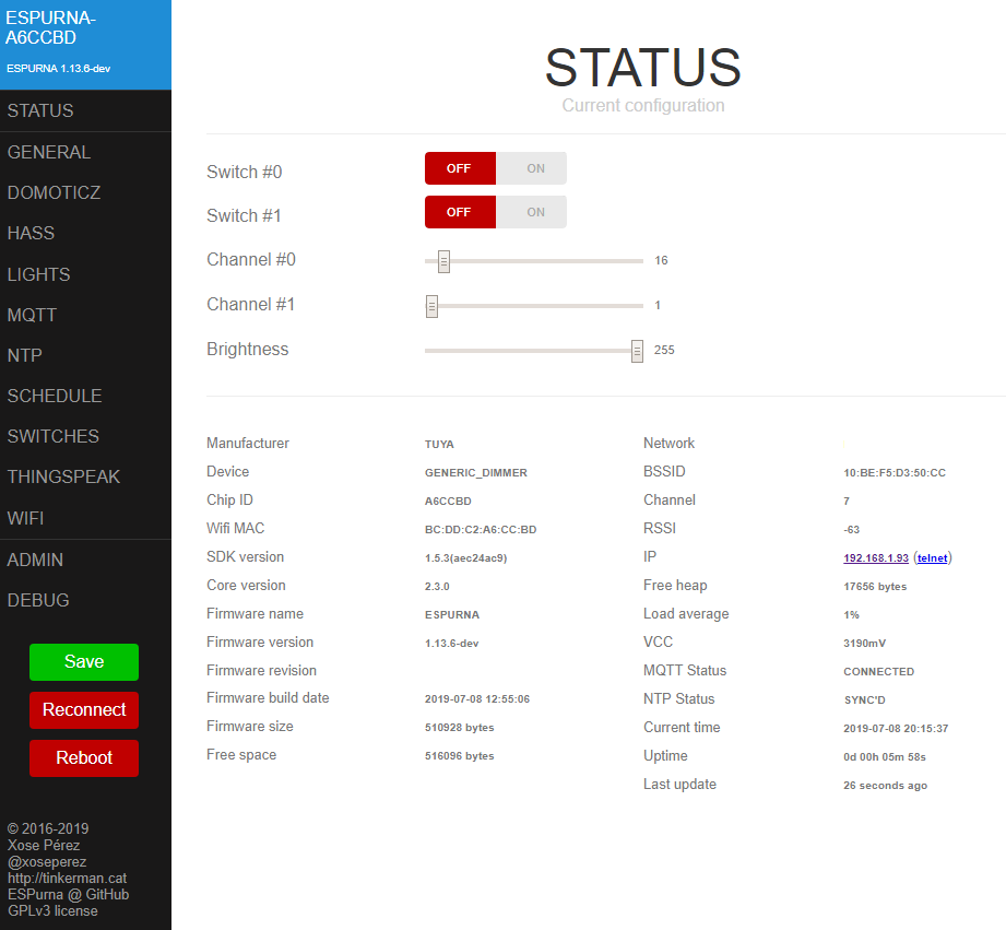
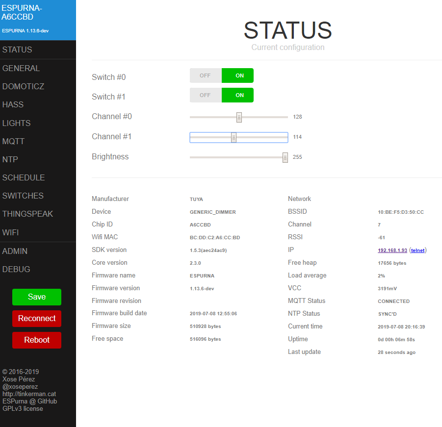
[436722] [WEBSOCKET] Requested action: relay
[436725] [RELAY] #1 scheduled ON in 0 ms
[436727] [RELAY] #1 set to ON
[436729] [MQTT] Sending TUYA001/relay/1 => 1 (PID 1)
[436732] [TUYA] OUT: 55aa0006000501010001010e
[436765] [TUYA] IN: 55aa0007000501010001010f
[436767] [RELAY] #0 scheduled ON in 0 ms
[436778] [RELAY] #0 set to ON
[436780] [MQTT] Sending TUYA001/relay/0 => 1 (PID 1)
[436783] [TUYA] IN: 55aa0007000501010001010f
[436785] [TUYA] OUT: 55aa00060008020200040000000116
[436797] [TUYA] IN: 55aa00070008020200040000001026
[436823] [TUYA] IN: 55aa00070008020200040000000117
[436927] [MQTT] Sending TUYA001/channel/0 => 1 (PID 1)
[436929] [MQTT] Sending TUYA001/channel/1 => 1 (PID 1)
[436930] [MQTT] Sending TUYA001/brightness => 255 (PID 1)
[437782] [RELAY] Setting relay mask: 3
[439314] [WEBSOCKET] Requested action: channel
[439418] [MQTT] Sending TUYA001/channel/0 => 1 (PID 1)
[439420] [MQTT] Sending TUYA001/channel/1 => 114 (PID 1)
[439420] [MQTT] Sending TUYA001/brightness => 255 (PID 1)
[439427] [TUYA] OUT: 55aa00060008020200040000007287
[439472] [TUYA] IN: 55aa00070008020200040000007288
[439473] [TUYA] IN: 55aa0007000501010001010f
[439497] [TUYA] IN: 55aa00070008020200040000008096
[439601] [MQTT] Sending TUYA001/channel/0 => 128 (PID 1)
[439603] [MQTT] Sending TUYA001/channel/1 => 114 (PID 1)
[439604] [MQTT] Sending TUYA001/brightness => 255 (PID 1)
But what happens with full channel brightness 255 (0xFF) or near it? Terminal has
channel 0 <value>
Any value above 241 stays at that value, upto and including 255 with MQTT reporting the same. Less than 239, a few seconds later the value jumps to plus 16.
This is strange too. It does slightly different things because other MCU is not powered down, but nothing specific to make switch go missing... Will test this more closely. You sure that the switch did not come up after page reload?
Did it loop because of hardware button toggle is this state?
No, the switch never appeared in the web GUI after a refresh of the page.
davebuk
on 8 Jul 2019
I accidentally added a second element when it can't update the current state. Happens only on boot and only without any predefined configuration. That phantom second response is the cause.
Double response from MCU can also be some clever way to guide transitions in tuya software, showing next possible step... (but only upwards for some reason). And sending values divisible without remainders does not seem to have any difference - one of the channel change logs sends value of 64, immediately responding with 78. Order is also something of note, it does send 16 and 1 instead of the usual value value+16 when channel value is 1.
Probably it can be safely ignored, comparing with "value"+-16 before doing anything with it
Will check it out
mcspr
on 9 Jul 2019
Tasmota seemed to do the same. Tasmota would remember the previous value and switch back on at that level, but then jump up a bit. Every ON/OFF would increase the brightness every time.
I use openHab to control everything, so had a rule that sets the dimmer value to 50% after being turned ON. After a few seconds it would jump to 56%. I've changed my rule for espurna so it now sets 111 and after a few seconds goes to 126.
davebuk
on 9 Jul 2019
@mcspr Hi there. Have you had a chance to look at making any changes to the code to remove the second auto configured channel and the possibility of the light returning to the previous brightness state when switching back on?
Thanks.
davebuk
on 30 Jul 2019
I haven't got a chance to test it yet, but I have updated the tuya branch. Will try in the morning if just ignoring dimmer state is sufficient enough. If not, I will try to add value filtering.
Software tests show that discovery problem should be fixed.
mcspr
on 31 Jul 2019
That will probably be fine to give better usage. I am current having issues controlling via MQTT as I have set that up to work WRT channel 1. Initial switch on levels are being set by rules in openHab.
davebuk
on 31 Jul 2019
With the current build or the previous one?
So the flow right now is:
- boot the device
- tuya module checks for saved channel / switch config, creates them if needed
- relay & light modules restore values from settings (brightness should always be restored, switch state is restored only when relay boot mode set to something else than the default)
- tuya discovery starts if previous step had not created any relays / channels, but state is received from the MCU
- any further brightness messages from the MCU are ignored and we only know about ON / OFF events (todo: setting)
mcspr
on 31 Jul 2019
Previous build, the one you made a while ago. I'll look to build tonight and upload/test tomorrow.
davebuk
on 31 Jul 2019
I have built but I am having some issues. I used the OTA update but for some reason the device lost the WiFi credentials and was showing the access point SSID. I could not connect to this using fibonacci or the previously set password. Power cycles made no difference.
I hardware flashed the same image and was able to set the device up while running from the 3v3 power source. Once connected to 240V I had access but the web GUI seemed to crash and I was unable to login and view the webpage. After a power cycle it came back for a while but would lock up again. Hard flashed the previous working firmware and similar lock ups/crashes.
Some libraries were updated in platformIO, maybe that has changed something. I'll try again with a flash wipe first then re flash. Do you know if there is a reason why the web GUI keeps locking up?
davebuk
on 2 Aug 2019
How big is the resulting .bin? I hope this has nothing to do with the settings overwriting themselves (again)
By locking up, you mean the board is resetting while using Web? Can you check the crash and info output? If ws console is unable to fully print them, serial or telnet are a way to go.
Library change was pretty mild and it was supposed to actually fix the crashes :/
mcspr
on 2 Aug 2019
The .bin came out at 501kb the previous 499kb. I'll see if I can get some time over the weekend to get more info.
When on 240V Its almost like the button is stuck. The device defaults to ON with the red LED regardless of firmware. With this version, pressing the button turns the LED OFF but it comes back on again after a second or two. Although the device is setup to connect to my WiFi and initally does, it is then shown as an access point in my WiFi list of SSIDs.
I updated my d1mini to the latest release of the main dev branch and that is working fine.
davebuk
on 2 Aug 2019
Managed to get the following from the console when powering the device using 3v3 and ground pins instead of 240V. There is no switch or channel on the status page but the web GUI is stable on the 3v3 supply.
[012938] [WEBSOCKET] Requested action: dbgcmd
[012946] [DEBUG] Latest crash was at 5618 ms after boot
[012948] [DEBUG] Reason of restart: 2
[012948] [DEBUG] Exception cause: 28
[012949] [DEBUG] epc1=0x40204ca2 epc2=0x00000000 epc3=0x00000000
[012950] [DEBUG] excvaddr=0x00000000 depc=0x00000000
[012952] sp=0x3fff2550 end=0x3fff2630 saved=0x0080

[012953] [DEBUG] >>>stack>>>
[DEBUG] 3fff2550: 00000001 00000001 00000001 4021049d
[DEBUG] 3fff2560: 00000000 3fff1120 00000002 40213d98
[DEBUG] 3fff2570: 00000002 3fff1120 00000003 40204ba4
[DEBUG] 3fff2580: 00000000 3ffe8cec 3ffe90fc 3ffe90fc
[DEBUG] 3fff2590: 000003fe 00000000 00000000 00000000
[DEBUG] 3fff25a0: 3fff0dfc 00000001 00000000 402168f4
[DEBUG] 3fff25b0: 40239edb 3ffef6e8 00162d1f 40223b3c
[DEBUG] 3fff25c0: 3fff41bc 4021b8e4 40222214 40230564
[DEBUG] <<<stack<<<
[013035] +OK
[015025] [TUYA] OUT: 55aa00000000ff
[018031] [TUYA] OUT: 55aa00000000ff
[021035] [TUYA] OUT: 55aa00000000ff
[024040] [TUYA] OUT: 55aa00000000ff
[027043] [TUYA] OUT: 55aa00000000ff
[030053] [TUYA] OUT: 55aa00000000ff
[033054] [TUYA] OUT: 55aa00000000ff
[036057] [TUYA] OUT: 55aa00000000ff
[038634] [WEBSOCKET] Requested action: dbgcmd
[038637]

---8<-------

[038637] [MAIN] ESPURNA 1.13.6-dev
[038638] [MAIN] [email protected]
[038639] [MAIN] http://tinkerman.cat

[038639] [MAIN] CPU chip ID: 0xA6CCBD
[038642] [MAIN] CPU frequency: 80 MHz
[038643] [MAIN] SDK version: 1.5.3(aec24ac9)
[038644] [MAIN] Core version: 2.3.0
[038644] [MAIN] Core revision: 9826c6d
[038645] [MAIN] Build time: 1562590506
[038646]
[038648] [MAIN] Flash chip ID: 0x1440C8
[038650] [MAIN] Flash speed: 40000000 Hz
[038650] [MAIN] Flash mode: DOUT
[038651]
[038652] [MAIN] Flash size (CHIP)   :  1048576 bytes /  256 sectors (   0 to  255)
[038657] [MAIN] Flash size (SDK)    :  1048576 bytes /  256 sectors (   0 to  255)
[038658] [MAIN] Reserved            :     4096 bytes /    1 sectors (   0 to    0)
[038659] [MAIN] Firmware size       :   510928 bytes /  125 sectors (   1 to  125)
[038660] [MAIN] Max OTA size        :   512000 bytes /  125 sectors ( 126 to  250)
[038661] [MAIN] EEPROM size         :     4096 bytes /    1 sectors ( 251 to  251)
[038664] [MAIN] Reserved            :    16384 bytes /    4 sectors ( 252 to  255)
[038665]
[038666] [MAIN] EEPROM sectors: 251, 250
[038667] [MAIN] EEPROM current: 250
[038667]
[038668] [MAIN] EEPROM:  4096 bytes initially |   993 bytes used (24%) |  3103 bytes free (75%)
[038671] [MAIN] Heap  : 32792 bytes initially | 19672 bytes used (59%) | 13120 bytes free (40%)
[038673] [MAIN] Stack :  4096 bytes initially |  1296 bytes used (31%) |  2800 bytes free (68%)
[038673]
[038674] [MAIN] Boot version: 31
[038675] [MAIN] Boot mode: 1
[038675] [MAIN] Last reset reason: Power on
[038678] [MAIN] Last reset info: flag: 0
[038679]
[038680] [MAIN] Board: TUYA_GENERIC_DIMMER
[038681] [MAIN] Support: ALEXA API BROKER BUTTON DEBUG_TELNET DEBUG_WEB DOMOTICZ HOMEASSISTANT LED MDNS_SERVER MQTT NTP SCHEDULER TELNET TERMINAL THINGSPEAK WEB
[038682] [MAIN] WebUI image: LIGHT
[038683]
[038684] [MAIN] Firmware MD5: 985646493448147cd338d45d48a8ae40
[038685] [MAIN] Power: 3197 mV
[038688] [MAIN] Power saving delay value: 10 ms
[038689]

---8<-------

[038690] +OK
[039061] [TUYA] OUT: 55aa00000000ff
[042065] [TUYA] OUT: 55aa00000000ff
[045073] [TUYA] OUT: 55aa00000000ff
[048076] [TUYA] OUT: 55aa00000000ff
[051086] [TUYA] OUT: 55aa00000000ff
[054088] [TUYA] OUT: 55aa00000000ff
[057093] [TUYA] OUT: 55aa00000000ff
[060006] [MAIN] System OK
[060101] [TUYA] OUT: 55aa00000000ff
If the led is ON... https://github.com/mcspr/espurna/commit/32e885f2b79563de5b5761a53478737365dda09f should help with the crash.
But now are there any channels autoconfigured?
mcspr
on 2 Aug 2019
Nothing when powered using 3v directly onto the board. When it works off 240v before the web GUI becoming unresponsive, channel 1 is shown but does not actually control anything. Brightness and on/off do not control the light attached.
As the first firmware I built is still crashing the web GUI, I can't easily see if the web controls are working.
davebuk
on 2 Aug 2019
mcspr@32e885f has fixed the LED switch state but unless the device is powered using 3v rather than the 240V, I can't get access to the web GUI or even connect to the WiFi access point. It is like the button is stuck down and resetting back to defaults. I have checked the button and it is working correctly so no harware failure.
I'll see if I can get something via serial connection at some point.
davebuk
on 3 Aug 2019
Do you mean the physical button? And info shows factory reset as the latest reset reason?
Can you post the full list of defines?
I can't see anything obvious about button presses. There was a rogue digitalWrite long time ago that was software-pressing button with virtual relays, but GPIO_NONE pin used now.
If anything, this part might be commented out to try this theory again
https://github.com/mcspr/espurna/blob/32e885f2b79563de5b5761a53478737365dda09f/code/espurna/relay.ino#L138
(// at the beginning of the line)
mcspr
on 3 Aug 2019
Yes its like the phyiscal button is setting the long press trigger on a standard Sonoff and resetting back to factory settings. The SSID comes up but when powered via 240V I can't access the device over WiFi. Either to connect to 192.168.4.1 or once my WiFi is configured (using 3volts) its DNS set IP adress.
The latest info when connected to 3v directly to the board (so no mains voltage and no buttons or channels are defined) is:
---8<-------

[033409] [MAIN] ESPURNA 1.13.6-dev
[033409] [MAIN] [email protected]
[033410] [MAIN] http://tinkerman.cat

[033411] [MAIN] CPU chip ID: 0xA6CCBD
[033411] [MAIN] CPU frequency: 80 MHz
[033412] [MAIN] SDK version: 1.5.3(aec24ac9)
[033414] [MAIN] Core version: 2.3.0
[033415] [MAIN] Core revision: 9826c6d
[033416] [MAIN] Build time: 1564832035
[033416]
[033417] [MAIN] Flash chip ID: 0x1440C8
[033419] [MAIN] Flash speed: 40000000 Hz
[033419] [MAIN] Flash mode: DOUT
[033423]
[033424] [MAIN] Flash size (CHIP)   :  1048576 bytes /  256 sectors (   0 to  255)
[033426] [MAIN] Flash size (SDK)    :  1048576 bytes /  256 sectors (   0 to  255)
[033430] [MAIN] Reserved            :     4096 bytes /    1 sectors (   0 to    0)
[033431] [MAIN] Firmware size       :   512272 bytes /  126 sectors (   1 to  126)
[033434] [MAIN] Max OTA size        :   507904 bytes /  124 sectors ( 127 to  250)
[033436] [MAIN] EEPROM size         :     4096 bytes /    1 sectors ( 251 to  251)
[033437] [MAIN] Reserved            :    16384 bytes /    4 sectors ( 252 to  255)
[033439]
[033440] [MAIN] EEPROM sectors: 251, 250
[033441] [MAIN] EEPROM current: 250
[033441]
[033442] [MAIN] EEPROM:  4096 bytes initially |   162 bytes used ( 3%) |  3934 bytes free (96%)
[033443] [MAIN] Heap  : 32696 bytes initially | 23256 bytes used (71%) |  9440 bytes free (28%)
[033446] [MAIN] Stack :  4096 bytes initially |  1424 bytes used (34%) |  2672 bytes free (65%)
[033447]
[033448] [MAIN] Boot version: 31
[033449] [MAIN] Boot mode: 1
[033449] [MAIN] Last reset reason: Software/System restart
[033452] [MAIN] Last reset info: Fatal exception:0 flag:4 (SOFT_RESTART) epc1:0x00000000 epc2:0x00000000 epc3:0x00000000 excvaddr:0x00000000 depc:0x00000000
[033453]
[033454] [MAIN] Board: TUYA_GENERIC_DIMMER
[033457] [MAIN] Support: ALEXA API BROKER BUTTON DEBUG_TELNET DEBUG_WEB DOMOTICZ HOMEASSISTANT LED MDNS_SERVER MQTT NTP SCHEDULER TELNET TERMINAL THINGSPEAK WEB
[033458] [MAIN] WebUI image: LIGHT
[033459]
[033460] [MAIN] Firmware MD5: e22831418ba6465482088e4cb5163301
[033461] [MAIN] Power: 3204 mV
[033464] [MAIN] Power saving delay value: 10 ms
[033465]

---8<-------
The defines I guess are the ones from hardware.h:
#elif defined(TUYA_GENERIC_DIMMER)

    #define MANUFACTURER        "TUYA"
    #define DEVICE              "GENERIC_DIMMER"

    #define LIGHT_PROVIDER      LIGHT_PROVIDER_TUYA
    #define LIGHT_CHANNELS      0
    #define RELAY_PROVIDER      RELAY_PROVIDER_LIGHT
    #define DUMMY_RELAY_COUNT   0
Oh, I thought you meant physical button with some customized config is causing trouble. I wonder what the problem is then... For WiFi connectivity specifically, maybe running erase.config will help it to connect to the AP. Or erasing last 16KiB region (need to check for esptool.py docs for that, can't remember what this needs to be outright). Full flash erase would also erase that region ofc.
And I had configured Tuya debugging apps with sort-of similar protocol, maybe I can find something there. No crashes btw
mcspr
on 3 Aug 2019
Commenting out line 138 doesn't help. :-) and I've been doing full erase and then flash using esptool.
I'll do more investigation. I have tried tasmota and that seems to be having similar web GUI issues. It seems it's only when powered via AC power, not DC.
davebuk
on 4 Aug 2019
Hi had a very early .bin file based on ITEAD_BNSZ01 and flashed that. I was able to run the device, connect to my WiFi, run info at debugging (see below) and refresh the web GUI while connected to 240V mains without any issues.
---8<-------

[078550] [MAIN] ESPURNA 1.13.6-dev
[078551] [MAIN] [email protected]
[078552] [MAIN] http://tinkerman.cat

[078553] [MAIN] CPU chip ID: 0xA6CCBD
[078556] [MAIN] CPU frequency: 80 MHz
[078558] [MAIN] SDK version: 1.5.3(aec24ac9)
[078563] [MAIN] Core version: 2.3.0
[078565] [MAIN] Core revision: 159542381
[078570]
[078571] [MAIN] Flash chip ID: 0x1440C8
[078574] [MAIN] Flash speed: 40000000 Hz
[078576] [MAIN] Flash mode: DOUT
[078579]
[078580] [MAIN] Flash size (CHIP)   :  1048576 bytes /  256 sectors (   0 to  255)
[078591] [MAIN] Flash size (SDK)    :  1048576 bytes /  256 sectors (   0 to  255)
[078597] [MAIN] Reserved            :     4096 bytes /    1 sectors (   0 to    0)
[078604] [MAIN] Firmware size       :   503472 bytes /  123 sectors (   1 to  123)
[078611] [MAIN] Max OTA size        :   520192 bytes /  127 sectors ( 124 to  250)
[078618] [MAIN] EEPROM size         :     4096 bytes /    1 sectors ( 251 to  251)
[078625] [MAIN] Reserved            :    16384 bytes /    4 sectors ( 252 to  255)
[078634]
[078636] [MAIN] EEPROM sectors: 251, 250
[078637] [MAIN] EEPROM current: 250
[078640]
[078642] [MAIN] EEPROM:  4096 bytes initially |  1095 bytes used (26%) |  3001 bytes free (73%)
[078650] [MAIN] Heap  : 33360 bytes initially | 18264 bytes used (54%) | 15096 bytes free (45%)
[078658] [MAIN] Stack :  4096 bytes initially |  1104 bytes used (26%) |  2992 bytes free (73%)
[078666]
[078667] [MAIN] Boot version: 31
[078668] [MAIN] Boot mode: 1
[078671] [MAIN] Last reset reason: Power on
[078674] [MAIN] Last reset info: flag: 0
[078677]
[078678] [MAIN] Board: ITEAD_BNSZ01
[078683] [MAIN] Support: ALEXA API BROKER BUTTON DEBUG_SERIAL DEBUG_TELNET DEBUG_WEB DOMOTICZ HOMEASSISTANT LED MDNS_SERVER MQTT NTP SCHEDULER TELNET TERMINAL THINGSPEAK WEB
[078699] [MAIN] WebUI image: LIGHT
[078700]
[078701] [MAIN] Firmware MD5: 671a9c9739650e77e9bb3c0708e9b2b8
[078708] [MAIN] Power: 3196 mV
[078710] [MAIN] Power saving delay value: 10 ms
[078714]
---8<-------
I then used the web OTA to update to the latest tuya dimmer version with the LED.ino change and the device rebooted. The web GUI never came up on the original IP address and the device is showing in the list of SSIDs that my laptop can connect to. I can connect to the ESPURNA-xxx SSID using my espurna password setup during inital install, but the web page at 192.168.4.1 does not connect or load anything.
Reapplying power to the the 3v and GND pins only allows the device to reconnect to my WiFi and I can see the web GUI again. Info gives:
---8<-------

[040775] [MAIN] ESPURNA 1.13.6-dev
[040776] [MAIN] [email protected]
[040777] [MAIN] http://tinkerman.cat

[040778] [MAIN] CPU chip ID: 0xA6CCBD
[040778] [MAIN] CPU frequency: 80 MHz
[040779] [MAIN] SDK version: 1.5.3(aec24ac9)
[040779] [MAIN] Core version: 2.3.0
[040780] [MAIN] Core revision: 9826c6d
[040781] [MAIN] Build time: 1564832035
[040781]
[040782] [MAIN] Flash chip ID: 0x1440C8
[040786] [MAIN] Flash speed: 40000000 Hz
[040787] [MAIN] Flash mode: DOUT
[040788]
[040789] [MAIN] Flash size (CHIP)   :  1048576 bytes /  256 sectors (   0 to  255)
[040794] [MAIN] Flash size (SDK)    :  1048576 bytes /  256 sectors (   0 to  255)
[040795] [MAIN] Reserved            :     4096 bytes /    1 sectors (   0 to    0)
[040796] [MAIN] Firmware size       :   512272 bytes /  126 sectors (   1 to  126)
[040798] [MAIN] Max OTA size        :   507904 bytes /  124 sectors ( 127 to  250)
[040800] [MAIN] EEPROM size         :     4096 bytes /    1 sectors ( 251 to  251)
[040800] [MAIN] Reserved            :    16384 bytes /    4 sectors ( 252 to  255)
[040801]
[040802] [MAIN] EEPROM sectors: 251, 250
[040802] [MAIN] EEPROM current: 250
[040805]
[040806] [MAIN] EEPROM:  4096 bytes initially |  1135 bytes used (27%) |  2961 bytes free (72%)
[040807] [MAIN] Heap  : 32720 bytes initially | 19400 bytes used (59%) | 13320 bytes free (40%)
[040810] [MAIN] Stack :  4096 bytes initially |  1248 bytes used (30%) |  2848 bytes free (69%)
[040811]
[040811] [MAIN] Boot version: 31
[040812] [MAIN] Boot mode: 1
[040813] [MAIN] Last reset reason: External System
[040813] [MAIN] Last reset info: Fatal exception:0 flag:6 (EXT_SYS_RST) epc1:0x00000000 epc2:0x00000000 epc3:0x00000000 excvaddr:0x00000000 depc:0x00000000
[040816]
[040817] [MAIN] Board: TUYA_GENERIC_DIMMER
[040818] [MAIN] Support: ALEXA API BROKER BUTTON DEBUG_TELNET DEBUG_WEB DOMOTICZ HOMEASSISTANT LED MDNS_SERVER MQTT NTP SCHEDULER TELNET TERMINAL THINGSPEAK WEB
[040819] [MAIN] WebUI image: LIGHT
[040822]
[040823] [MAIN] Firmware MD5: e22831418ba6465482088e4cb5163301
[040824] [MAIN] Power: 3218 mV
[040826] [MAIN] Power saving delay value: 10 ms
[040828]
---8<-------
[040828] +OK
Could the secondary MCU or some other part of the hardware be effecting the device from running properly when its trying to control the power transistor? Remember it works fine with the ITEAD_BNSZ01 firmware installed on 240V?!
davebuk
on 4 Aug 2019
Ok, so autodiscovery was stumbling on a similar bug with switches too - domoticz module specifically was broken, as it was not expecting switch number to suddenly change after the boot sequence.
Fixed by the https://github.com/xoseperez/espurna/compare/32e885f...0c2f285d (git pull to update, as always)
edit: New manual setting to ignore states - tuyaFilter. Set to 1 to ignore switch changes, 2 to ignore channel changes, 3 (i.e. the result of 1 << 2) to ignore both. Previous build always ignored channels, but this seems like a better way to handle this.
mcspr
on 5 Aug 2019
Right. All sort of working again, good work. Device is configured and stable running from 240V. Light is controllable from web GUI (ON/OFF/Channel#0 level) and only one switch is shown after a power cycle. The brightness (Channel #0) level does not return to previous values, and after switch selected to ON, #0 value drops to 1. Physical button turns output and LED ON/OFF but connected light appears to be off as channel#0 has value 1.
As before, channel level jumps 16 after changing to a new level.
[886151] [MQTT] Sending TUYA001/channel/0 => 65 (PID 1)
[886153] [MQTT] Sending TUYA001/brightness => 255 (PID 1)
[886156] [TUYA] =>: 55aa00060008020200040000004156
[886194] [TUYA] <=: 55aa00070008020200040000004157
[886206] [TUYA] <=: 55aa0007000501010001010f
[886221] [TUYA] <=: 55aa00070008020200040000005167
[886326] [MQTT] Sending TUYA001/channel/0 => 81 (PID 1)
[886328] [MQTT] Sending TUYA001/brightness => 255 (PID 1)
The other strange thing is changing the 'brightness' level changes the reported 'channel' level in the debug screen, but doesn't effect the actual brightness level or the value reported on the status screen. The text below was after setting channel level to 72.
[943474] [WEBSOCKET] Requested action: channel
[943578] [MQTT] Sending TUYA001/channel/0 => 44 (PID 1)
[943580] [MQTT] Sending TUYA001/brightness => 200 (PID 1)
[943583] [TUYA] =>: 55aa0006000802020004000000394e
[943620] [TUYA] <=: 55aa0007000802020004000000394f
[943632] [TUYA] <=: 55aa0007000501010001010f
[943645] [TUYA] <=: 55aa0007000802020004000000485e
[943747] [MQTT] Sending TUYA001/channel/0 => 56 (PID 1)
[943749] [MQTT] Sending TUYA001/brightness => 200 (PID 1)
Next issue :-) I can control light ON/OFF via mqtt xxxx/realy/0/set 0 or 1 as payload, but level xxxx/channel/0/set does not work. xxxx/channel/0 reports the level in the debug screen but doesn't seem to update on the mqtt client.
davebuk
on 5 Aug 2019
As before, channel level jumps 16 after changing to a new level.
See message above, set tuyaFilter 2 should do it.
edit: Maybe this also can be a build-time flag, #define TUYA_DP_FILTER ...?
But, update before testing that, https://github.com/xoseperez/espurna/compare/0c2f285...6d1906a so that tuyaFilter does not filter out button presses too.
Second commit also "fixes" brightness behaviour. Before, it used raw channel value without brightness, so changing it did nothing as channel value never changes. Now, the channel value is raw value times brightness / 100, same as MQTT reports.
I wonder how this was never an question for anyone (anyone?) using lights with alexa, because they use the same API
mcspr
on 6 Aug 2019
Perfect!!
set tuyaFilter 2 using 0c2f285...6d1906a stops the plus 16 issue and the light returns ON to the previous level. I wasn't sure what the filters were for! Web GUI allows ON/OFF/#0 changes, these update to MQTT and MQTT control changes the web GUI. Physical button turns light ON/OFF and returns to previous brightness when turned ON. Channel#0 value is left unchanged in the web GUI status page and reports 0 to MQTT when turned OFF .
My MQTT brightness issue is my fault. Tasmota used 0-100% as does openHAB. I'll need to set a rule to convert 0-255 to percent. Using android app MQTT Dash works perfectly. The only tiny issue is if channel#0 (brightness) level is set to 0, the light switches OFF, which is probably correct, so I may set minimum brightness values in openHAB.
Unfortunately .bin comes out at 501Kb so I couldn't do an OTA flash.
Excellent work in getting this working. Is there any other things you would like me to try?
davebuk
on 6 Aug 2019
Can't you try a 2 step ota flash using one of the (tiny) core images? Releases
 ColinShorts
on 6 Aug 2019
ColinShorts
on 6 Aug 2019
I haven't tried as the Wiki says the second flash requires a different method of flashing after using the smaller, 300kb file. It suggests you can't OTA using the web GUI the >500kb file using the 300kb .bin? I've done it before flashing the minimal Tasmota then a big espurna.bin but want sure about espurna small to espurna big. 😊
davebuk
on 6 Aug 2019
I've not been unlucky enough to notice that was the case, but you should be able to do it OTA using Arduino (I never got that working first time around) or platformio (this always just worked for me).
ColinShorts
on 6 Aug 2019
On another device I have just disabled some of the functions I don't need using custom.h to reduce the size. I didn't want to mess around too much and break Max's code!
OTA using platformio is a job for another day for me, but thanks for the heads up, I'll definitely look into it.
davebuk
on 6 Aug 2019
Nice. Since it does not blow up the runtime anymore, might as well add this to the dev branch and work out further quirks.
Regarding brightness, maybe some constant can control it in the settings.
https://github.com/xoseperez/espurna/compare/dev...mcspr:format-fixes adds LIGHT_MIN_VALUE define that is set for every channel manipulation routine as the min value. Also LIGHT_MIN_BRIGHTNESS to accompany it. But idk how it would interact with tuya thing, there could be some bugs. Plus, that branch also should be around 500 bytes less in size
(edit note that it needs to be merged locally, there is no Tuya module there!)
Default configuration total size grew about ~3KB since the latest release.
You can safely disable some of those, like DEBUG_TELNET_SUPPORT & TELNET_SUPPORT (-3KB interestingly enough), THINGSPEAK_SUPPORT (around the same 3KB). Light support somewhat bulky for just white lights and Tuya module itself could also use some size improvements.
Debugging altogether can also be disabled, since those strings take around 16KB, but that's another issue, since terminal is hidden away in the WebUI for some reason.
mcspr
on 7 Aug 2019
Hi!
Dunno if I'm really correct here, but it fit's pretty good and I did not want to open a new issue yet.
I have a pretty similar Tyua device, called "Smart Garage Door Controller" (https://www.amazon.de/Garagentor%C3%B6ffner-Maxcio-Kompatibel-Steuerung-Betriebsaufzeichnung/dp/B07Q57CQ2B/.
Opened up it looks like this

It is based on a TYWE2S (ESP8285) and a STM8S003F4 mcu just like the dimmer discussed here. It also ran tuya firmware originaly. Also relay, led an door-closed sensor are controlled by mcu via serial tuya protocol commands.
Switch relay: SerialSend5 55 aa 00 06 00 05 01 01 00 01 01 0e
sonoff-2168 ESP-MQT: tele/sonoff/RESULT = {"SerialReceived":"55aa03070005010100010011"}
sonoff-2168 ESP-MQT: tele/sonoff/RESULT = {"SerialReceived":"55aa03070005010100010112"}

Close and open the door-sensor:
sonoff-2168 ESP-MQT: tele/sonoff/RESULT = {"SerialReceived":"55aa0307000565010001007555aa03070005010100010011"}
sonoff-2168 ESP-MQT: tele/sonoff/RESULT = {"SerialReceived":"55aa0307000565010001017655aa03070005010100010112"}

Got feedback from another DpId, guess it's the LED controlled by MCU:
sonoff-2168 ESP-MQT: tele/sonoff/RESULT = {"SerialReceived":"55aa0307000807020004000000001e"}
I managed to flash tasmota and espeasy firmware so far. At least with tasmota I was able to communicate with the device via the "SerialSend5 55aa..." commands.
Unfortunately there is obviously no direct support for it in espurna so far.
Do you guys think, when adding the "tuya" dimmer it would be possible to get support for the smart door controller as well?
 riogrande75
on 8 Aug 2019
riogrande75
on 8 Aug 2019
@riogrande75 Hey. The way build works right now, lights support is optional and is enabled by using LIGHT_PROVIDER_TUYA and some automatic dependency resolution in the headers (ref https://github.com/xoseperez/espurna/issues/1729#issuecomment-517934441). Instead, you can just add TUYA_SUPPORT set to 1 and it will build with just basic switches, since we don't support anything else right now.
edit: and I mean this https://github.com/xoseperez/espurna/compare/dev...mcspr:experimental/tuya branch, as it is not yet merged here
2nd SerialReceived shows 2 messages: "55aa03070005650100010075" and "55aa03070005010100010011". Both door sensor and switch send out boolean values which we treat as relay internally (and I would expect that the firmware will create 2 virtual relays on boot).
Specific DPid are 65 (sensor) and 1 (switch)
mcspr
on 9 Aug 2019
@mcspr You said about adding the current code to the Dev branch. If that is there case I'll mark this thread as closed.
davebuk
on 9 Aug 2019
@davebuk issue will auto-close once it is merged btw, since it will be a pr
mcspr
on 11 Aug 2019
Hi @mcspr
I am having some issues trying to build using the 2.5.2 core. The standard build seems fine, but when I change the platform to 2_5_2 I get:
In file included from .pio\libdeps\tuya-generic-dimmer\NoFUSS\src\NoFUSSClient.cpp:21:0:
.pio\libdeps\tuya-generic-dimmer\NoFUSS\src\NoFUSSClient.h:27:31: fatal error: ESP8266httpUpdate.h: No such file or directory

***************************************************************************
* Looking for ESP8266httpUpdate.h dependency? Check our library registry!
*
* CLI  > platformio lib search "header:ESP8266httpUpdate.h"
* Web  > https://platformio.org/lib/search?query=header:ESP8266httpUpdate.h
*
***************************************************************************

 #include <ESP8266httpUpdate.h>
                               ^
compilation terminated.
*** [.pio\build\tuya-generic-dimmer\liba15\NoFUSS\NoFUSSClient.cpp.o] Error 1
==================================================================== [FAILED] Took 203.49 seconds ====================================================================
or
Linking .pio\build\tuya-generic-dimmer\firmware.elf
c:/users/samsung laptop/.platformio/packages/toolchain-xtensa/bin/../lib/gcc/xtensa-lx106-elf/4.8.2/../../../../xtensa-lx106-elf/bin/ld.exe: cannot open linker script
file ../ld/eagle.app.v6.common.ld: No such file or directory
collect2.exe: error: ld returned 1 exit status
*** [.pio\build\tuya-generic-dimmer\firmware.elf] Error 1
==================================================================== [FAILED] Took 317.96 seconds ====================================================================
Do you have any idea what could be the problem? Thanks.
davebuk
on 8 Oct 2019
Oops, sorry! Second one is because of the build system updates, I thought I had merged the #1559 there, guess not. You can manually cherry-pick the 437424aaac28a6022124864f911b10aab2e1626f to make it work right now.
No idea about the nofuss, but if you are not using it just remove the NoFUSS line from the lib_deps = ... list in the .ini
I need to update the tuya branch though... Hopefuly soon
mcspr
on 9 Oct 2019
The cherry pick worked, (once I found out how to do it)! Tuya dimmer now on 2.5.2 @ 559KB.
For my future reference, from platformio terminal, type: git cherry-pick <commit-hash> (git cherry-pick 437424a)
davebuk
on 9 Oct 2019
So how difficult is it to get this device working? Because I was thinking about perhaps getting one of these. However my other option might be to use a low voltage control instead (eg esp3288 to 5v adc) and then connect that to a seperate ac dimmer via a potentiometer. Not decided yet.
 dreamcat4
on 28 Oct 2019
dreamcat4
on 28 Oct 2019
The device is working fine. I'm using it connected via mqtt to openHAB. I need to update the flashing details at the top of the post as I have marked the wrong pin on the chip for the GPIO 0 pin. If you are happy to use a soldering iron to get to the Tx/Rx pins, everything else is fairly straight forward.
@mcspr is going to look to get this added to the master branch. It may be easier to build once he's done that.
davebuk
on 28 Oct 2019
Thank you @davebuk all of that sounds really lovely. And look forward to that. All very impressive & I look forward to this.
Actually for myself am still considering the other option because this specific dimmer is leading edge Triac. Well the device i wish to drive is probably going to be a 200w AC fan (1 amp on uk mains). What I heard from discussion with somebody else is that: most of these cheaper and more low end dimmer switches (such as this one) are not normally designed with inductive loads in mind. (As in: motors), and therefore might not include a 'snubber'. Whatever that is.
However I was also wondering if maybe this device can actually be modified to include extra components added for to make a snubber, or a capacitor / whatever it is to work against the inductive load. Therefore to be making a better handling for those usage scenarios. Or maybe it doesnt actually matter! so much for a lower wattage load which isn't going to kick back so much. And not to bother. This device is still a leading edge one though again: I don't really know how much that matters either. You get the initial spike and maybe it would be kinder to be smoothing out that leading edge impulse. I mean: kinder to whatever the other equipment is we are connecting to it. This may also be true for certain types of led lighting etc. Which then end up having their own converters inside them with flickering issues and whatnot.
SO what I am really saying is that: this device is already great for many other applications. And I also hope maybe we can figure out how to modify it to make it work even better. If anybody else has any ideas about that. Perhaps we can create a post in some other community to get such help. Like in the eevblog forums or elsewhere.
Personally won't be getting one of these to play with myself for quite a while yet. As thinking to add wifi functionality comes right at the end of my own project. In no hurry. I mean I guess I could just order one anyway from ali. They are only 8 quid from china. But it's also a case of actually finding the time to mess around with it once it gets here.
dreamcat4
on 28 Oct 2019
OK in the end I spent an extra £4 and got this other one instead https://www.aliexpress.com/item/33031283451.html
Being traillng edge. So in about a month or 2 months should arrive and I can open a new separate issue... for yet another dimmer device (more is better, right?). Still very grateful for all the hard work that already went into this issue here. Because it's so well explained, and all may be used to help get the next one working! Thanks again.
dreamcat4
on 29 Oct 2019
Like you said, I doubt either device circuit will drive an AC fan directly due to the inductive load of the motor. If the fan already has a 3 speed selection it could be controlled with some relays. The other option is to look for a PWM to AC inductive load convertor and use a standard GPIO output from a Sonoff basic setup as a light dimmer. No idea if such a circuit exists!
davebuk
on 29 Oct 2019
Hi, davebuk
I've bought this dimmer a few weeks ago. I'm not planning to change the firmware for now, but I have an easy question: it's dimmable only through the app or voice...is there any way (soldering pins) to get the dimmer function with the physical button?
 falconchips
on 4 Nov 2019
falconchips
on 4 Nov 2019
@mcspr @falconchips Out of the box I'd say no. There was no indication in the instructions that you could dim with the switch. Max did start looking at a button hold implementation that would allow on/off and brightness up/down functions, but I'm not sure how far he got. The code side is pretty much over my head I'm afraid!
The other option is to have remote mqtt switches that send bright/dim payloads. I'm using openHAB as an mqtt server and interface but you may be able to use another protocol within espurna to achieve this?
davebuk
on 4 Nov 2019
@davebuk
No, I also bought another Tuya dimmer that allows dimmer with the button but it has so much lag (you press the button and light turns on about 1,5 sec after; it's annoying) so I'm not really into changing firmware, just wondering if may be an easy way to add dimmer function with the button.
falconchips
on 5 Nov 2019
Hi,
First of all, great work and many thanks for putting effort in supporting Tuya based dimmer modules!
I'm trying to get espurna to work with this Tuya dimmer.(https://www.aliexpress.com/item/33014039692.html?spm=a2g0o.productlist.0.0.20a4267fJQMyXa&algo_pvid=0e68e72d-4480-4f8e-be8c-2534b7ae7e00&algo_expid=0e68e72d-4480-4f8e-be8c-2534b7ae7e00-9&btsid=85f8b6de-845a-497b-8876-f05b80f3ba90&ws_ab_test=searchweb0_0,searchweb201602_8,searchweb201603_55

I am able to flash the experimental/tuya fimware onto the device. But I won't get it to work.
I am receiving serial data from the secondary MCU. But there is no serialdata send, according to the WebUI debug screen.
I've got the device working with Tasmota, using this setup guide.
https://blakadder.github.io/templates/qs-wifi_D01_dimmer.html
Do I need to make changes tot the config header files, prior to compiling?
I just compiled the experimental/tuya branche for the tuya-generic-dimmer environment.
Did I overlook something?
 keesdekraker
on 17 Nov 2019
keesdekraker
on 17 Nov 2019
@keesdekraker Sorry, we are dealing with different devices and serial protocols based on the https://blakadder.github.io/templates/qs-wifi_D01_dimmer.html
Whenever the button is pressed there are 50/60 Hz pulses on the S switch input. The frequency detection circuit (below) is connected to GPIO13 of the ESP8266 chip. These pulses must be processed as a switching signal with a counter. The ESP8266 then sends commands accordingly via the hardware serial interface for dimming operation, which are handled by a second microcontroller (STM8S003F3 MCU). The serial communication at 9600 baud is simple, just one command with changing brightness xx values: >> FF 55 xx 05 DC 0A <<
But, protocol is much simpler, we just need small light provider that does a serial write with that data packet
mcspr
on 18 Nov 2019
@mcspr Thanks for your quick reply.
That makes sense.
The switch input on GPIO13 can also be binded as a BUTTON_SWITCH or BUTTON.
The net frequency is used for timing the button press, but timing can also be done using the conventional way in espurna.
My programming skills are far too little to implement the communication protocol.
I will stick to Tasmota for the moment. And will look into the the espurna code in more detail to see if I can grasp the espruna code a bit more.
keesdekraker
on 18 Nov 2019
@keesdekraker I think the extent of the code for writing would be to add a new PROVIDER check in this function:
https://github.com/xoseperez/espurna/blob/383d5a8a5d918b8052d30112ef08a846a60837ea/code/espurna/light.ino#L550-L581
Channel value would be the "brightness" value, e.g.:
#if LIGHT_PROVIDER == LIGHT_PROVIDER_QSD01
    const uint8_t buffer[6] = {0xFF, 0x55, _light_channel[0].current, 0x05, 0xDC, 0x0A};
    Serial.write(buffer, 6);
#endif
Serial support is a bit complicated to configure though, as we need to have DEBUG_SERIAL_SUPPORT set to 0 and SERIAL_SPEED set to 9600 and some place to actually do a Serial.begin(SERIAL_SPEED). Current place to add such support would be:
https://github.com/xoseperez/espurna/blob/383d5a8a5d918b8052d30112ef08a846a60837ea/code/espurna/system.ino#L244-L248
mcspr
on 20 Nov 2019
Good night, I got Tasmota flash via OTA on this device, everything works reasonably well, but the dimmer behaves incorrectly, I would like to know if anyone could properly configure his '' DIMMERRANGE '' in Tasmota.
 LeandroSPereira
on 4 Jan 2020
LeandroSPereira
on 4 Jan 2020
Related issues
 eercanayar
·
3Comments
eercanayar
·
3Comments
 prankousky
·
3Comments
prankousky
·
3Comments
 MariusLaurinaitis
·
9Comments
MariusLaurinaitis
·
9Comments
 fernando-p-jesus
·
6Comments
fernando-p-jesus
·
6Comments
 germaguire
·
7Comments
germaguire
·
7Comments