Espurna: Magic Home LED Controller, ZJ-WFMN-A V1.1
I have one with "ZJ-WFMN-A V1.1" printed on it which according to https://github.com/arendst/Sonoff-Tasmota/wiki/MagicHome-with-ESP8285 is a version with the ESP8285.
Is this supported by any of the existing profiles?
 peterhoeg
All 22 comments
@racerx, did you comment and then remove the comment again?
peterhoeg
on 17 Nov 2018
Sorry, I did . I was on the wrong issue. I have this same unit and got it to work using the configuration that I created here: https://github.com/arendst/Sonoff-Tasmota/wiki/MagicHome-with-ESP8285
I then realized that I was commenting in espurna and not on tasmota so I deleted it.
 racerx
on 17 Nov 2018
racerx
on 17 Nov 2018
This is slightly off-topic @racerx, but how exactly do you mount/hold the pogo pins to the pads instead of soldering?
peterhoeg
on 20 Nov 2018
Hi Peter,
I am soldering directly to the board with a header and a FTDI TTL-232R3V3 serial adapter. Please know that the signals are 3V3 but VCC on that adapter is 5V and will fry your module if you connect it.
Only need to connect TX,RX and GND to the adapter.
During power up you need to hook IO0 and GND together. I did this with a male and female jumper cable.


racerx
on 20 Nov 2018
Thank you for the super detailed instructions.
I was hoping that it was possible without actually soldering (I managed to flash a B1 by holding a 5 pin header pin very still) and so the mention of pogo pins got my hopes up but I guess that's not doable without a 3d printer jig.
I'll try this out on the weekend, thanks again!
peterhoeg
on 21 Nov 2018
It worked and no soldering was required. Crocodile plugs to connect RX, TX and GND (with plastic on the other side of the PCB to ensure there were no shorts), a free wire for IO0 and a male dupont for power (I powered it from the FTDI instead of the normal power plug). Then it was just about holding my hands very still while the firmware uploaded.
peterhoeg
on 21 Nov 2018
Very cool! So you covered the whole other side of board with plastic and then powered 5V to the normal power input with the red wire in my picture?
racerx
on 21 Nov 2018
A man smarter than me would probably have taken photos to document this while everything was open and connected...
you covered the whole other side of board with plastic
Correct, I simply used a small plastic bag folded a few times to cover the entire other side (the side with the chips)
- TX was connected using a crocodile plug from the left (using your photos for direction).
- RX was also connected using a crocodile plug from the left but with a small piece of plastic to cover the pad it had to "reach over"
- GND was connected to the top GND from the right also with a crocodile plug and a small piece of jumper wire used to connect to IO0 (the lower GND was not used at all)
- Power was supplied to the V33 pad using 3.3V from the FTDI
peterhoeg
on 22 Nov 2018
Added support for the A/B variants in the dev branch.
@racerx @peterhoeg Do you mind if I add your flashing instructions to the wiki?
 xoseperez
on 9 Dec 2018
xoseperez
on 9 Dec 2018
@xoseprez yes, please add.
Thanks,
Rex
racerx
on 9 Dec 2018
Ah. Now I know why my attempt to flash had been unsuccessful.
 DOSputin
on 10 Dec 2018
DOSputin
on 10 Dec 2018
@xoseperez - do you want a wiki PR for the wiki changes? I can write it properly.
Do you think it would be appropriate to make recommendations on the hardware wiki? I just received a H801 and flashed it last night which took about 5 minutes in total - I personally would never bother with the Magic Home again and just use H801 instead.
peterhoeg
on 10 Dec 2018
Interesting about the H801. I'll have to try to come by one of those.
Amazon sent me a magichome ZJ-WFMN-A V1.1 _by accident_ ( errors = free stuff 🥇)
Found this issue after trying to flash the other magichome firmware with no joy.
I got the new ZJ-WFMN-A V1.1 firmware compiled and flashed, and minicom talks to it over a PL2303-TTL usbserial on Mac OS High Sierra. Messed about a bit with the config that way, get it set up to my liking.
Thanks for all the hard work fellows!
Only problem now, is it seems need to re-config the RGB channels?
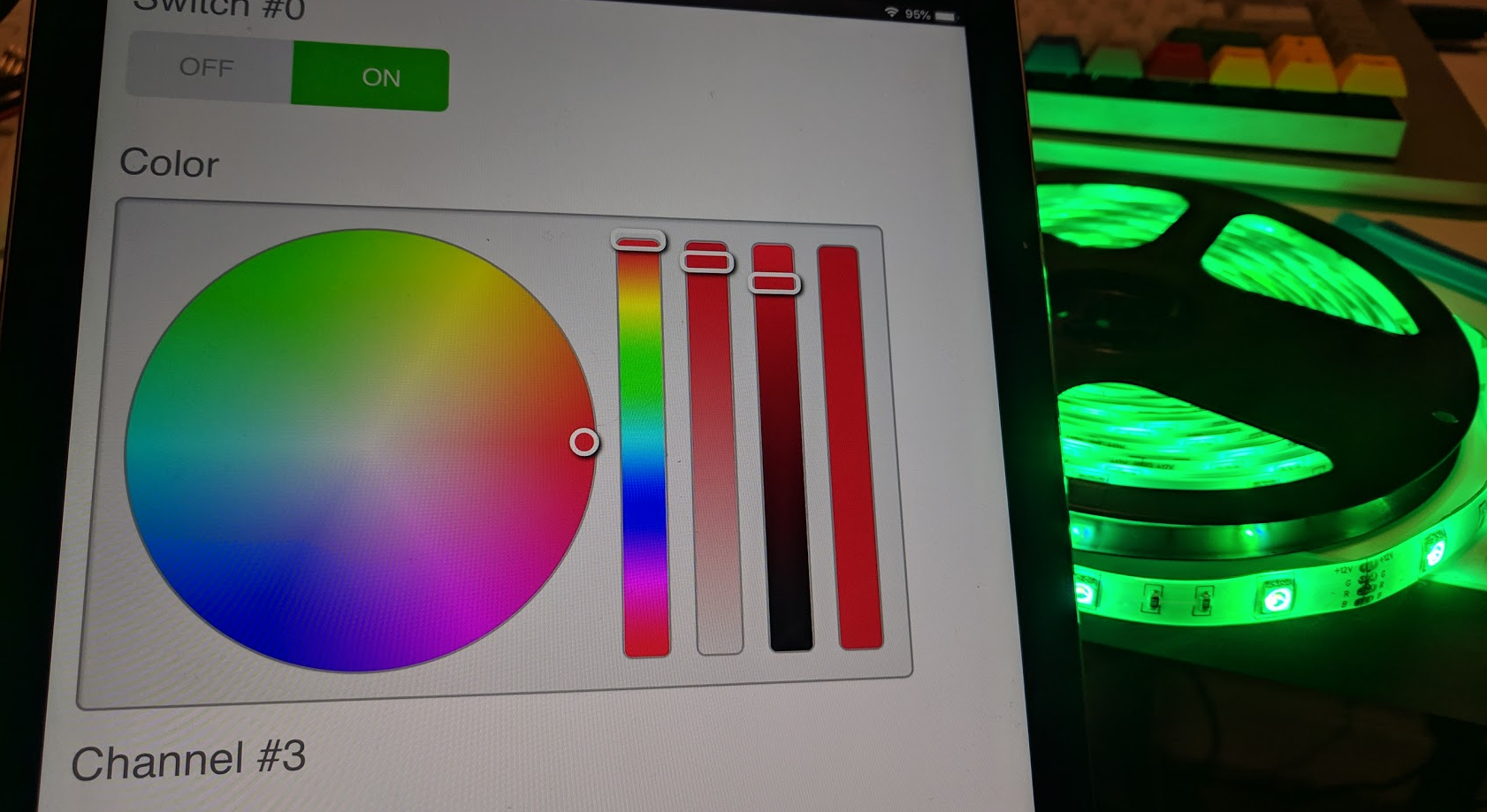
DOSputin
on 10 Dec 2018
@DOSputin These MagicHome devices are kind of a nightmare. They all have different channel configurations. The ones I set for these models are based on the documentation above in the Tasmota project. What GPIO control what channels in your device?
@peterhoeg It will really help me if you write a PR for the wiki with the docs. Thank you. Yes, some devices are easier to flash than others. Still, the MagicHome are small and use to feature RF/IR which the H801 doesn't.
xoseperez
on 10 Dec 2018
@DOSputin
The pinout on 1.1 is different. I added the correct pins to the sonoff wiki here:
https://github.com/arendst/Sonoff-Tasmota/wiki/MagicHome-with-ESP8285
racerx
on 10 Dec 2018
@racerx
I have an magichome ZJ-WFMN-A V1.1 but i had to change the gpio pin for the white channel from 14 to 15.
hardware.h
#elif defined(MAGICHOME_ZJ_WFMN_A_11)

// Info
#define MANUFACTURER        "MAGICHOME"
#define DEVICE              "ZJ_WFMN_A_11"
#define RELAY_PROVIDER      RELAY_PROVIDER_LIGHT
#define LIGHT_PROVIDER      LIGHT_PROVIDER_DIMMER
#define DUMMY_RELAY_COUNT   1

// Light
#define LIGHT_CHANNELS      4
#define LIGHT_CH1_PIN       12      // RED
#define LIGHT_CH2_PIN       5       // GREEN
#define LIGHT_CH3_PIN       13      // BLUE
#define LIGHT_CH4_PIN       15      // WHITE
#define LIGHT_CH1_INVERSE   0
#define LIGHT_CH2_INVERSE   0
#define LIGHT_CH3_INVERSE   0
#define LIGHT_CH4_INVERSE   0

// IR
#define IR_SUPPORT          1
#define IR_RX_PIN           4
#define IR_BUTTON_SET       1`
 Floriansimmer
on 23 Dec 2018
Floriansimmer
on 23 Dec 2018
Does someone have original firmware file for magic home rgb with ir remote zj wfmn-a v1.1 ?
 mafyata
on 15 Apr 2019
mafyata
on 15 Apr 2019
It worked and no soldering was required. Crocodile plugs to connect RX, TX and GND (with plastic on the other side of the PCB to ensure there were no shorts), a free wire for IO0 and a male dupont for power (I powered it from the FTDI instead of the normal power plug). Then it was just about holding my hands _very_ still while the firmware uploaded.
Hello!
I have also a "zj wfmn-a v1.1" and i was able to successfully put a new firmware on it.My problem is that after i download the new software, the ESP8285 does not broadcast any SSID.
I have 3 main questions:
- The GPIO pin must be shorted with GND only on boot-up?
2.Can you tell me please what firmware did you use in order to successfully use the Controller?
3.Is there any way of "reseting" the controller, or just the wi-fi module (like on H801 with on/off for 4/5 times)?
Thank you,
Vlad
 vsterian
on 11 Jul 2019
vsterian
on 11 Jul 2019
My problem is that after i download the new software, the ESP8285 does not broadcast any SSID.
I have 3 main questions:
- The GPIO pin must be shorted with GND only on boot-up?
Yes, that's at least how I did.
- Can you tell me please what firmware did you use in order to successfully use the Controller?
Just regular espurna, but self-compiled.
- Is there any way of "reseting" the controller, or just the wi-fi module (like on H801 with on/off for 4/5 times)?
Not that I am aware of, no.
peterhoeg
on 11 Jul 2019
Just wanted to chime in that I also have a ZJ_WFMN_A_11 that needed the white GPIO change to 15, are there older devices with GPIO 14?
Should we update the value or create a second config?
 sovanyio
on 4 May 2020
sovanyio
on 4 May 2020
@sovanyio 2nd config might be better, naming it though...
Since 37f62477728bc8ff621e102286e4cc188310aab4 we can change PWM pin at runtime through ltDimmerGPIO# setting, where # 0...4 maps to hard-coded LIGHT_CH#_PIN 1...5
edit: typos
 mcspr
on 5 May 2020
mcspr
on 5 May 2020
Oh nice I didn't see that in the wiki when I was looking--ended up compiling the modification myself. Runtime change :+1:
sovanyio
on 7 May 2020
Related issues
 mstjerna
·
6Comments
mstjerna
·
6Comments
 FlorianSW
·
3Comments
FlorianSW
·
3Comments
 pascal1404
·
7Comments
pascal1404
·
7Comments
 vaidyasr
·
10Comments
vaidyasr
·
10Comments
 fernando-p-jesus
·
6Comments
fernando-p-jesus
·
6Comments
Most helpful comment
@xoseprez yes, please add.
Thanks,
Rex