Good morning people!
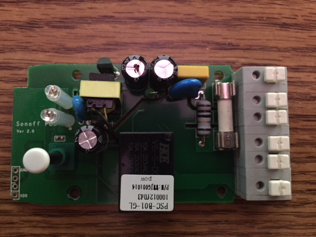
I bought 4 Sonoff Pow, but came to version 2.0.
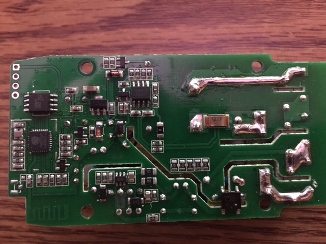
It does not have the pins exposed to upload the firmware.
In addition to other small visual differences of the board.
Has it ever managed to put the ESPurna in a Sonoff Pow v2.0?
Here is the equipment photo:
Thank you very much in advance.
 analistamarcioprado
All 16 comments
Hi,
I am almost sure that the 4 holes in the left bottom corner of your first picture are the pins needed for flashing firmwares.
GND, RX, TX, VCC (3.3V).
After making the proper connections the procedure should be the same as for the other/older models.
Good luck, cheers
Eric
 erkgh
on 15 Jun 2018
erkgh
on 15 Jun 2018
Hi,
That's right.
My concern is that the hardware is different ...
analistamarcioprado
on 15 Jun 2018
The POW 2 is supported, solder some headers to those 4 pins and connect a
programmer, press and hold the button an power the board to boot into flash
mode.
On Fri, 15 Jun 2018, 22:23 Marcio Prado, notifications@github.com wrote:
Hi,
That's right.
My concern is that the hardware is different ...
—
You are receiving this because you are subscribed to this thread.
Reply to this email directly, view it on GitHub
https://github.com/xoseperez/espurna/issues/947#issuecomment-397732151,
or mute the thread
https://github.com/notifications/unsubscribe-auth/AArHt2wu9JyfDpRFmzGR7UyNlUdS58Mlks5t9BemgaJpZM4UpXl-
.>
Xose Pérez
@xoseperez
http://linkedin.com/in/xoseperez
http://tinkerman.cat
 xoseperez
on 16 Jun 2018
xoseperez
on 16 Jun 2018
I have the Same Sonoff POW and they are supported .
Just flash them the same way you flash any sonoff
Here is a Video by Dr z
 seetendra
on 17 Jun 2018
seetendra
on 17 Jun 2018
Thanks for the contributions.
I did not solder the pins. I fit in a way that made contact. But I must have done something wrong.
My Sonoff when connected via USB does not turn on any led.
When it is connected to the mains, there is a period of time with the LED on for a long time and then off.
Is there any possibility of recovering the equipment?
analistamarcioprado
on 17 Jun 2018
I dont think your Sonoff is bad
Believe me it is very difficult to do that. I have done all kinds of stuff with the POW V2 that i have and they are all working fine
Just make sure that your flashing them with 3.3v on the FTDI adapter and not 5v
Also use the ESPEASY method that is the fasted and you don't have to Hold on to the Sonoff With the Pins for a very long time
I never solder pin to the Sonoff that i flash there is no need to do that just hold the pins in place for some time and there should be no problem.
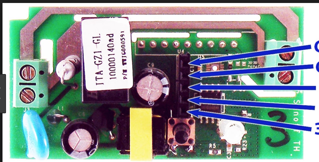
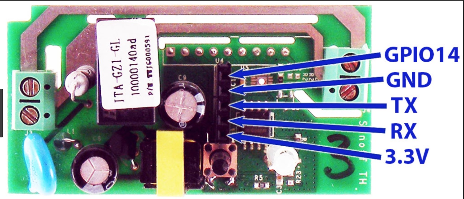
Wiring the FTDI adapter is al important make sure you have that correct.
seetendra
on 18 Jun 2018
seetendra
on 18 Jun 2018
Thanks for the info.
The pinning issue I believe I did not make a mistake. I used this one (although it is version 1.0):
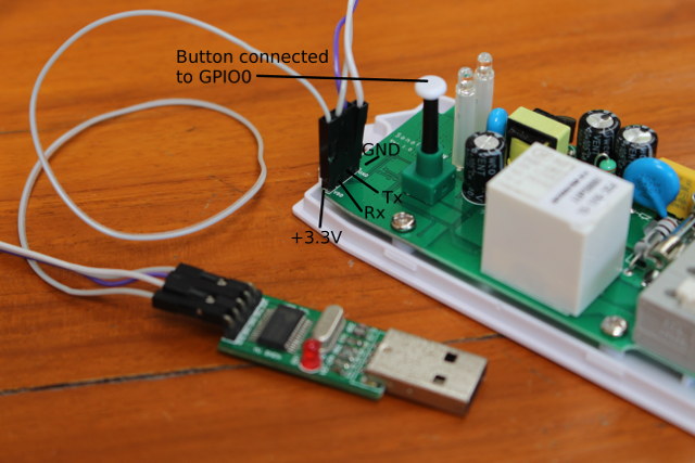
How is this method called ESPEASY?
analistamarcioprado
on 18 Jun 2018
Download the file from the link
https://github.com/letscontrolit/ESPEasy/releases/download/mega-20180619/ESPEasy_mega-20180619.zip
then follow the video
https://www.youtube.com/watch?v=BCEU8Ijmkds&t=9s
seetendra
on 19 Jun 2018
Be very careful with the Sonoff POW, because the internal pins can sometimes be at 110V/220V relative to earth! So not connect it to mains volltage while flashing it!
 schweini
on 22 Jun 2018
schweini
on 22 Jun 2018
Staff thank you all.
The problem was very simple. More for a beginner in Sonoff Pow gave a lot of work to find out.
The problem is the sequence of the pinout.
All the tutorials I saw in the sequence were this:
GND
TX
RX
TRUE
But is the correct sequence in Sonoff Pow ver 2.0 the following:
GND
RX
TX
TRUE
Hugs.
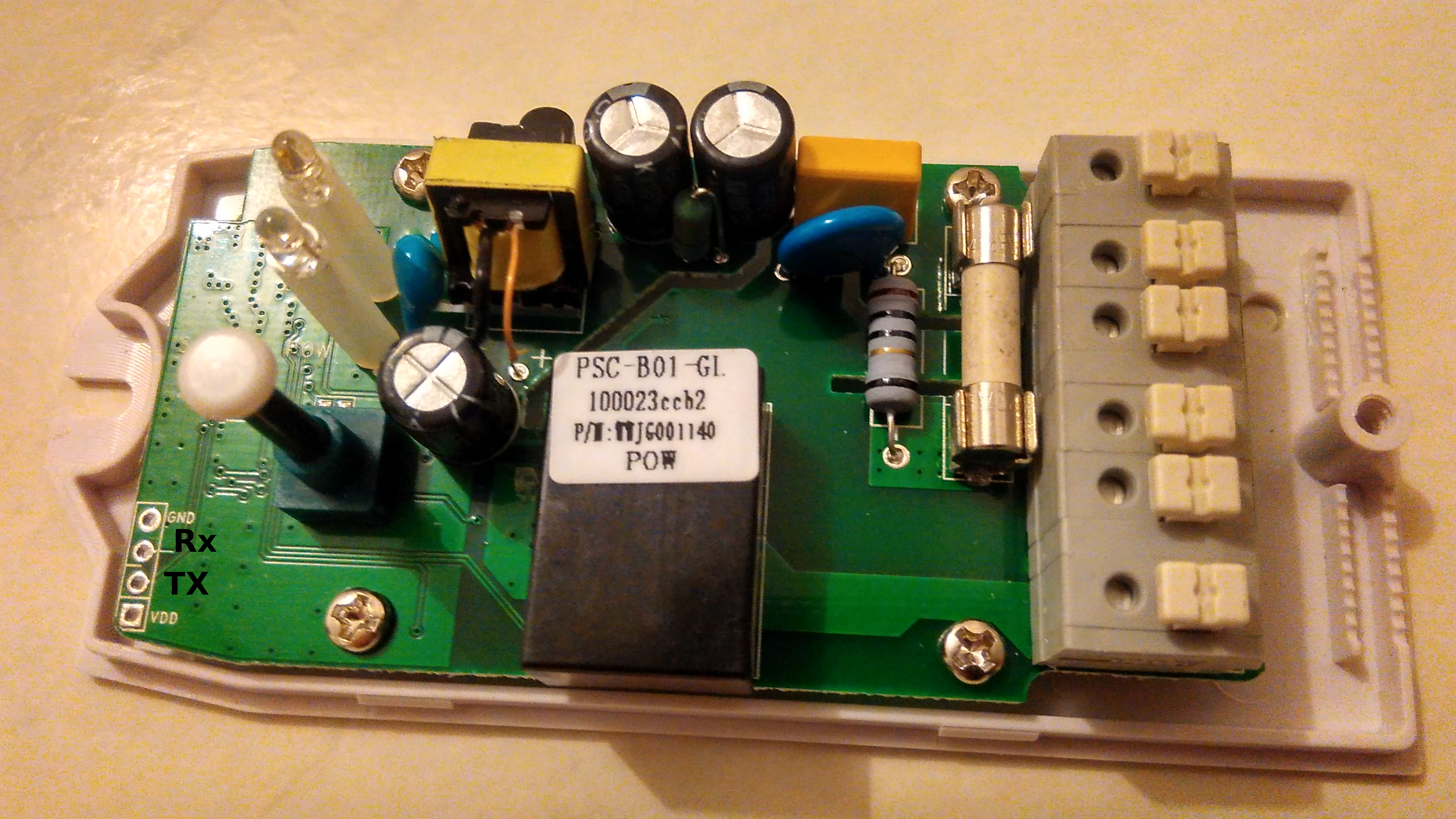
analistamarcioprado
on 22 Jun 2018
Guys, I think I said something wrong.
Does the TX di Sonoff pin have to be connected to the RX or TX of the USB interface?
analistamarcioprado
on 22 Jun 2018
If it doesn't work one way, switch RX and TX leads and try again. As long as you connect the negative and positive leads the correct way and use the correct voltage (usually 3.3V) it'll be fine.
 ColinShorts
on 22 Jun 2018
ColinShorts
on 22 Jun 2018
Ah yes. Nice!
I did this and it really worked.
Once again thank you for your attention.
analistamarcioprado
on 22 Jun 2018
Please, can put as solved.
analistamarcioprado
on 25 Jun 2018
Cool
xoseperez
on 25 Jun 2018
Related issues
 MariusLaurinaitis
·
9Comments
MariusLaurinaitis
·
9Comments
 eercanayar
·
3Comments
eercanayar
·
3Comments
 namezero
·
7Comments
namezero
·
7Comments
 fernando-p-jesus
·
6Comments
fernando-p-jesus
·
6Comments
 rradar
·
3Comments
rradar
·
3Comments